

Page 1
Page 2
Page 3

Foreword
This manual has be en designed for train e d ser vi ce personnel and describes how to maint ai n and repair.
This manual is not intended for general users.
This manual comprises the following chapters.
Chapter 1: Printer Illustration
P2-
Chapter 2: Decomposition
P6-
Chapter 3: Assembly
P19-
Chapter 4: Adjustments, Printing test
P37-
Chapter 5: Maintenance/Lubrication
P47-
Chapter 6: Troubleshooting
Chapter 7: Component List
Chapter 8: Parts Exchange
Chapter 9: Software
P50-
P53-
P60-
P68-
1/71
Page 4
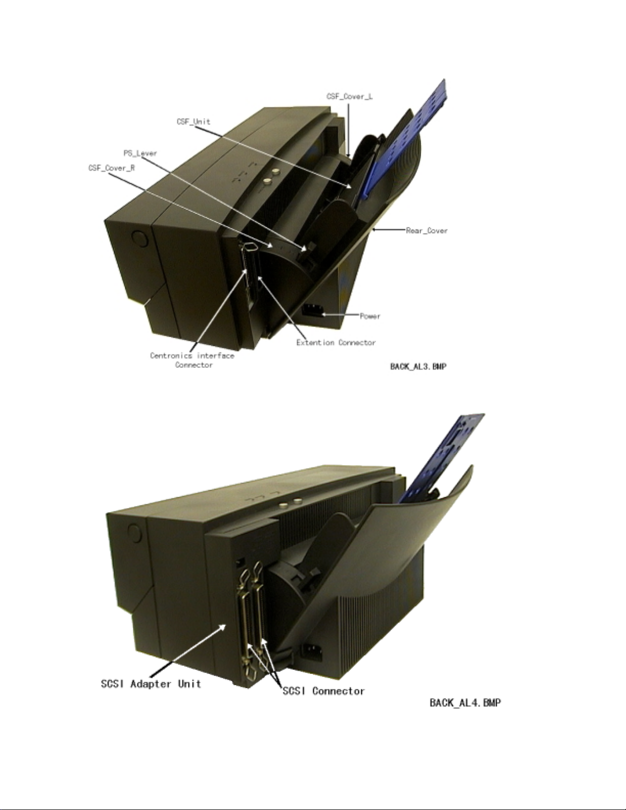
Chapter 1: Printer Illustration
2/71
Page 5
3/71
Page 6
4/71
Page 7

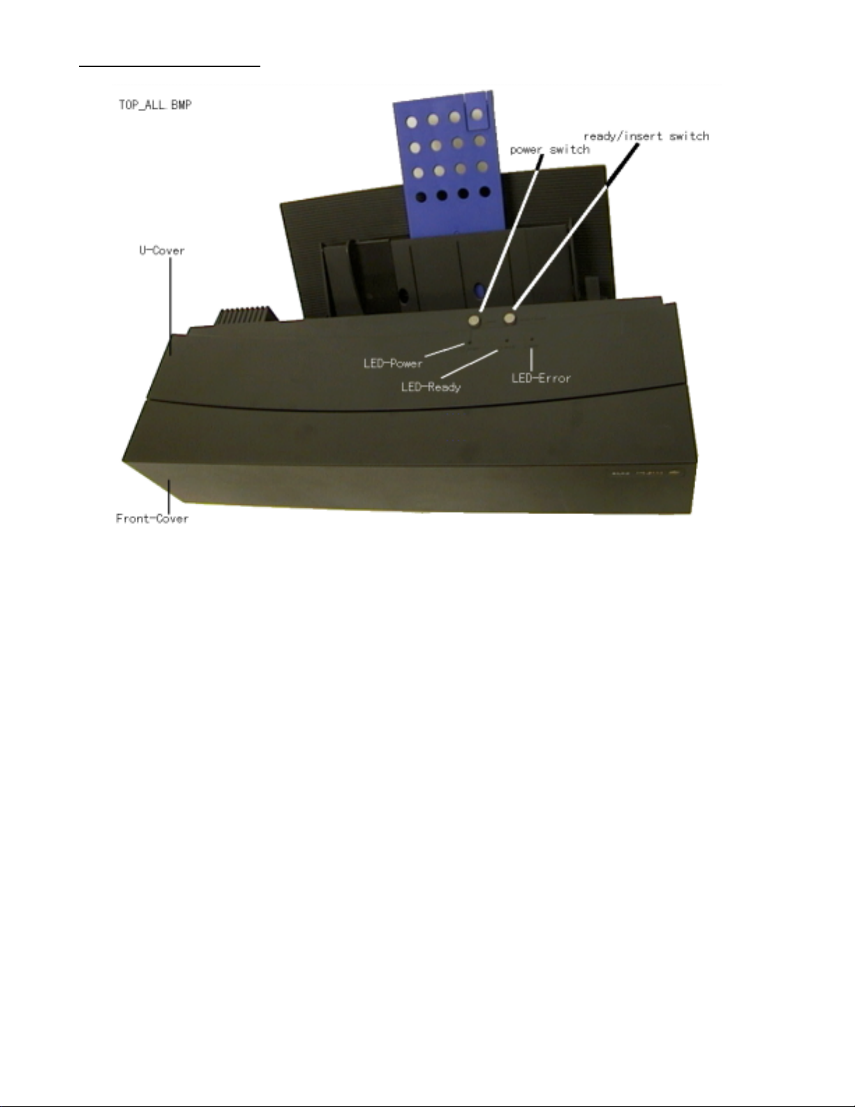
1.1 Operation Panel
1) power Switch
Printer power
2) ready/insert Switch
Self-printing ,Paper intake/eject
3) LED
Power : Indicates if power is turn ed on. This LED also blinks the HEX dump/self printing status.
Ready : This LED blinks when the print data is receiv ed. Moreover, when an error occ urs, LED is
turned off.
error : Indicates printer is in an error st at e.
Blinking: Alarm Off: Normal
5/71
Page 8
Chapter 2: Decomposition
R
t
L
t
)
L
d
P
t
C
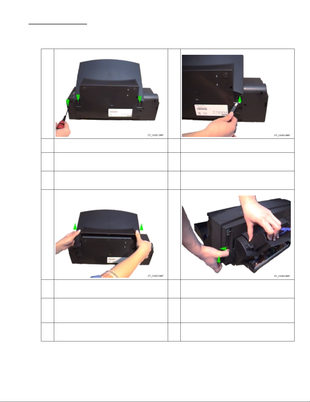
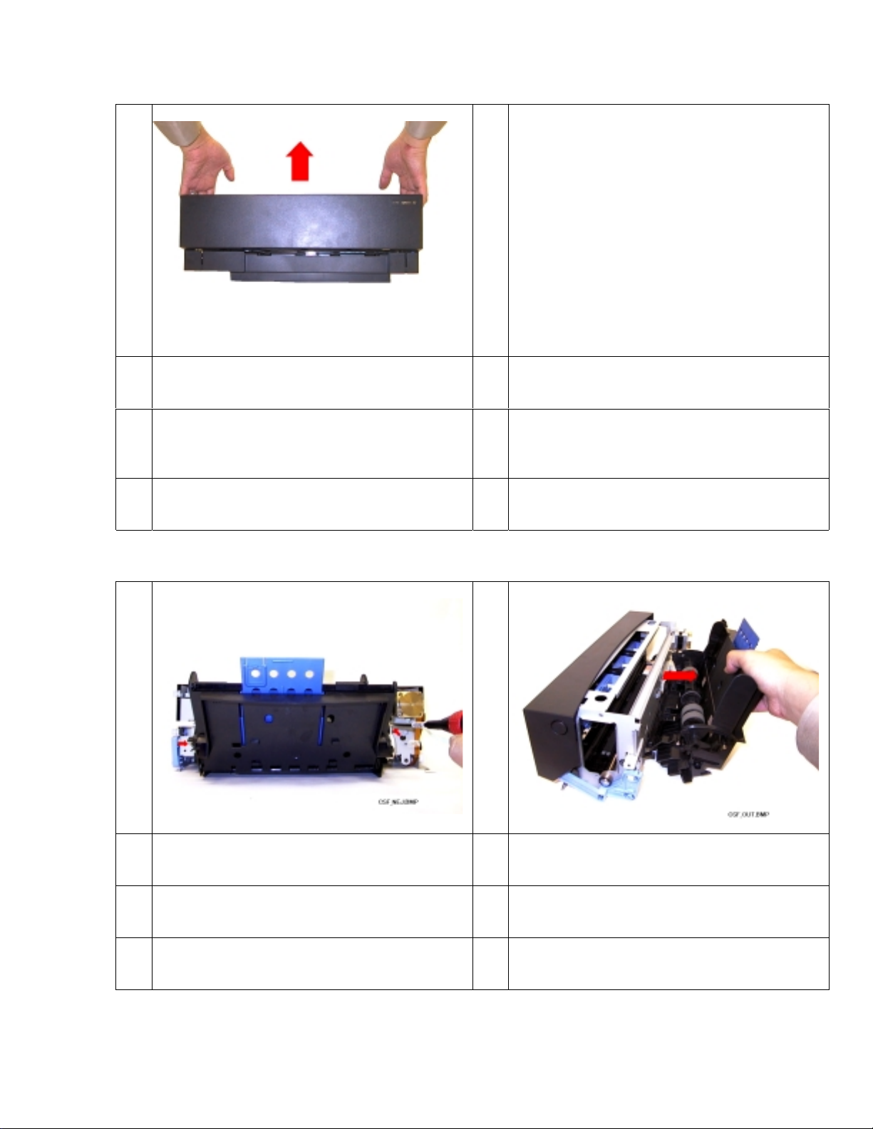
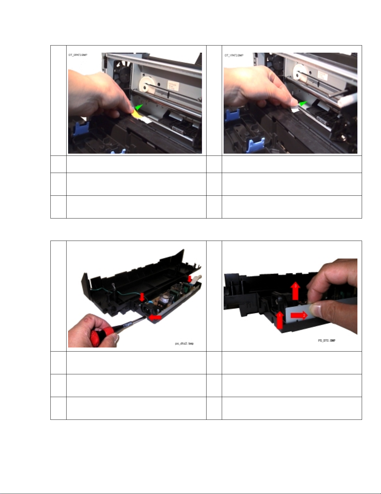
2.1 Detaching of Cases
1
emove the screw (M3*L10P) in the place of
he arrows 1, 2 and 3.
3 4
2
ift the point of Rear Cover with tweezer s in
he direction of the arrow .(2 places
ift up and remove the Rear Cover in the
irection of the arrow.
ull right side of U Cover Assy af t er
Front Cover is opened in the direction of
he arrow 1, and lift up the lower part of U
over Assy in the direction of th e ar r ow 2.
6/71
Page 9
5
I
U
t
f
I
l
m
u
R
t
i
R
t
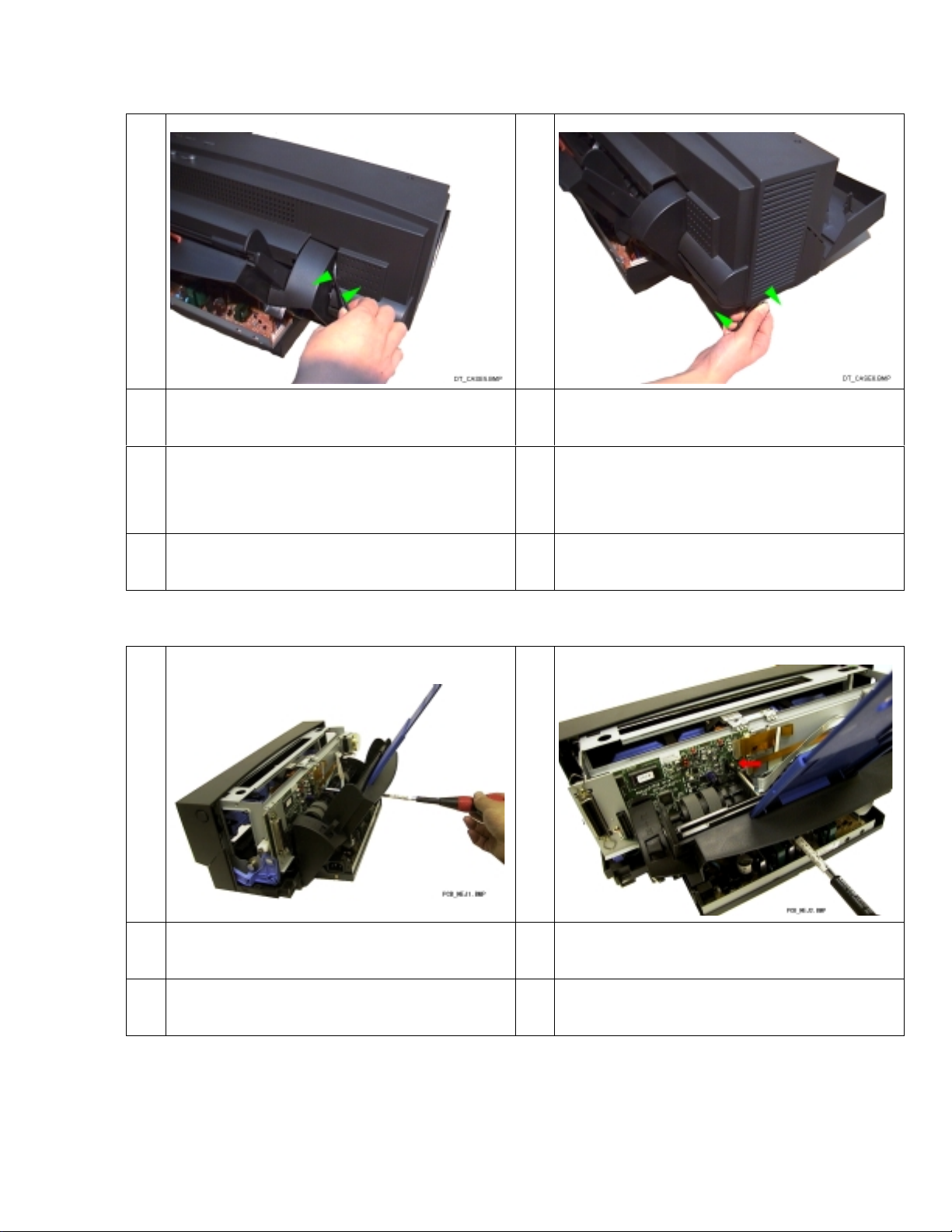
6
nsert the tweezers in the space between
_Cover Assy and CSF Cover_L, remove
he CSF Cover_L. Next, pull out FAN cable
rom the connector of pow er supply.
2.2 Detaching of Main_PCB
1
nsert the tweezers through the opening of
ower part of left side of U_Cover Assy and
ove tweezers in the direction of the arrow
ntil clicks. And remove U_Cover Assy.
2
emove the DC_Tape from the connect or on
he Main_PCB side and the screw-driver is
nserted from the hole shown in Figure.
emove the screw (M3*L6TP) in the place of
he arrow.
7/71
Page 10
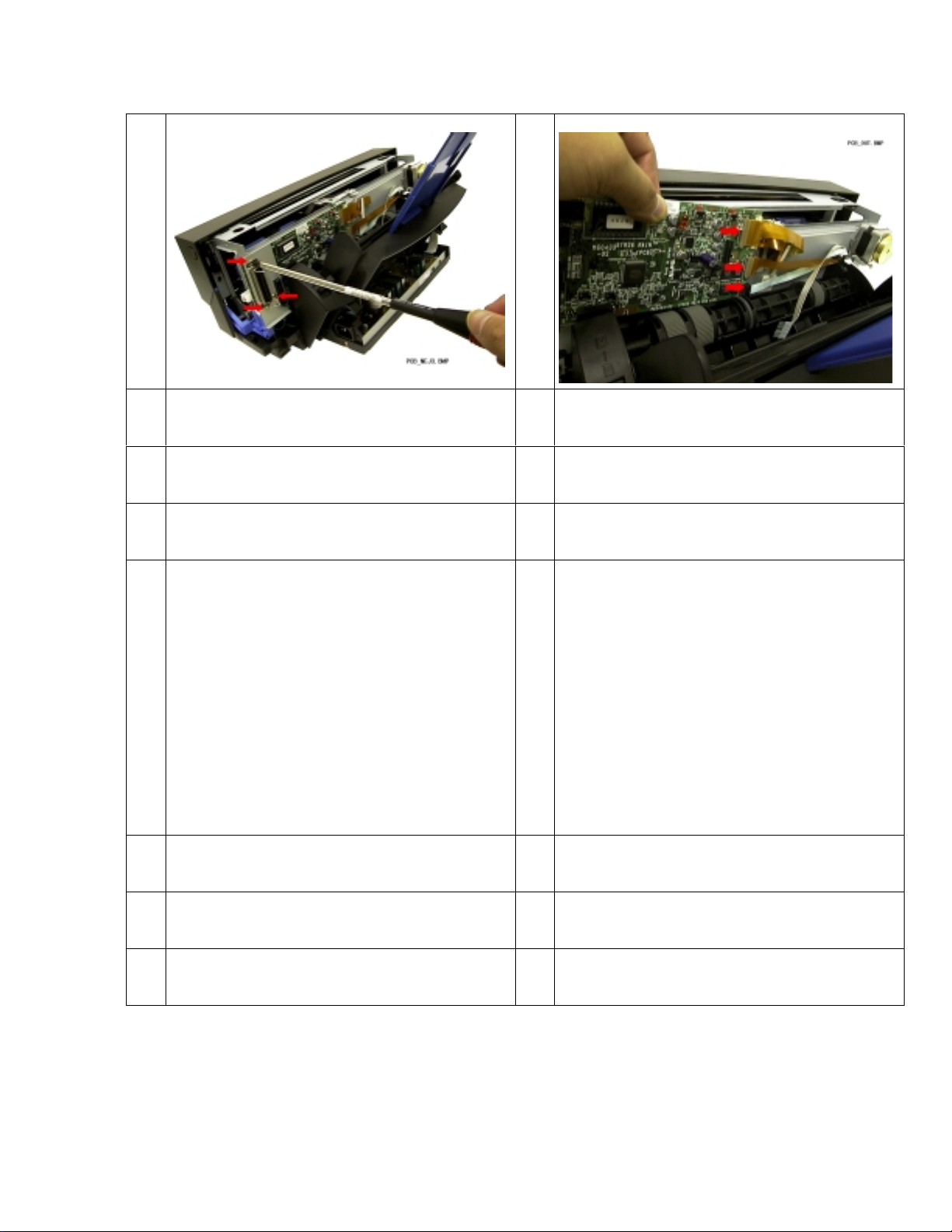
3
R
3
2
T
f
4
emove the screws(1,2-M3*L12,
-M3*L6BIND) in the place of the arrows 1,
and 3.
ake off the one harness and the t hree FP C’s
rom connectors in the place of t he arrows.
8/71
Page 11
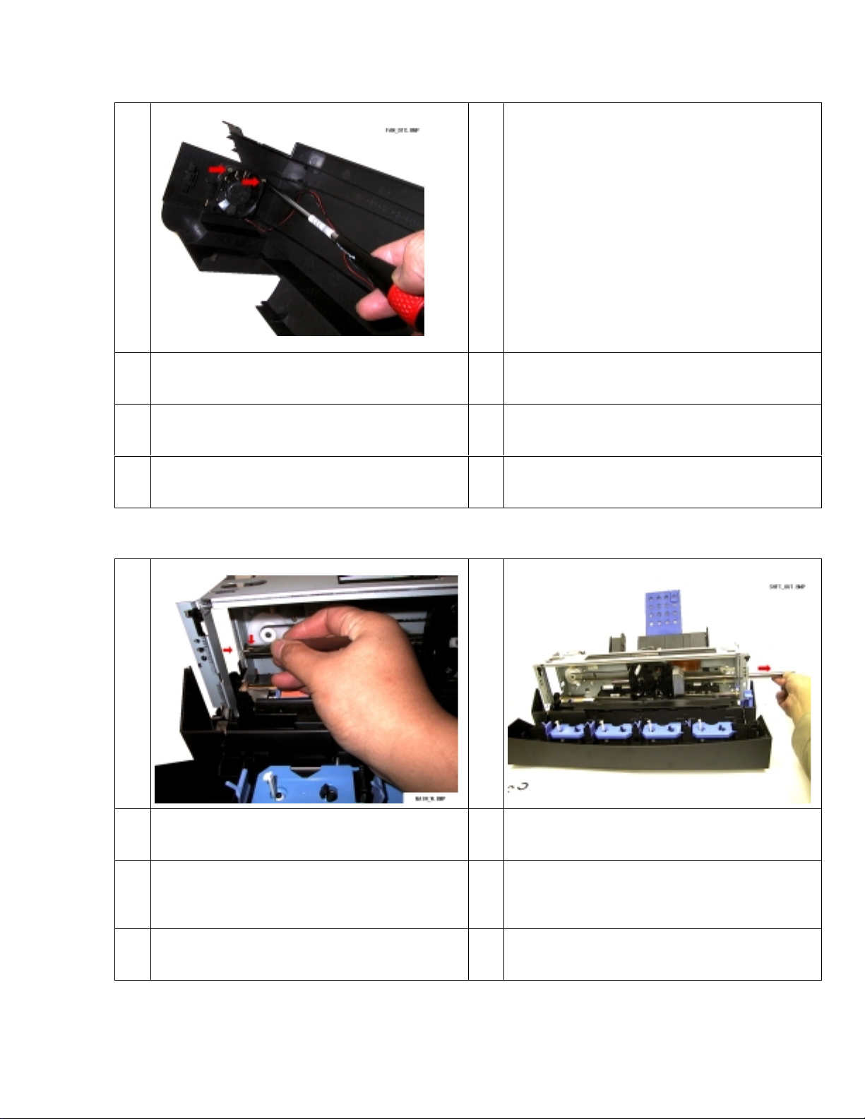
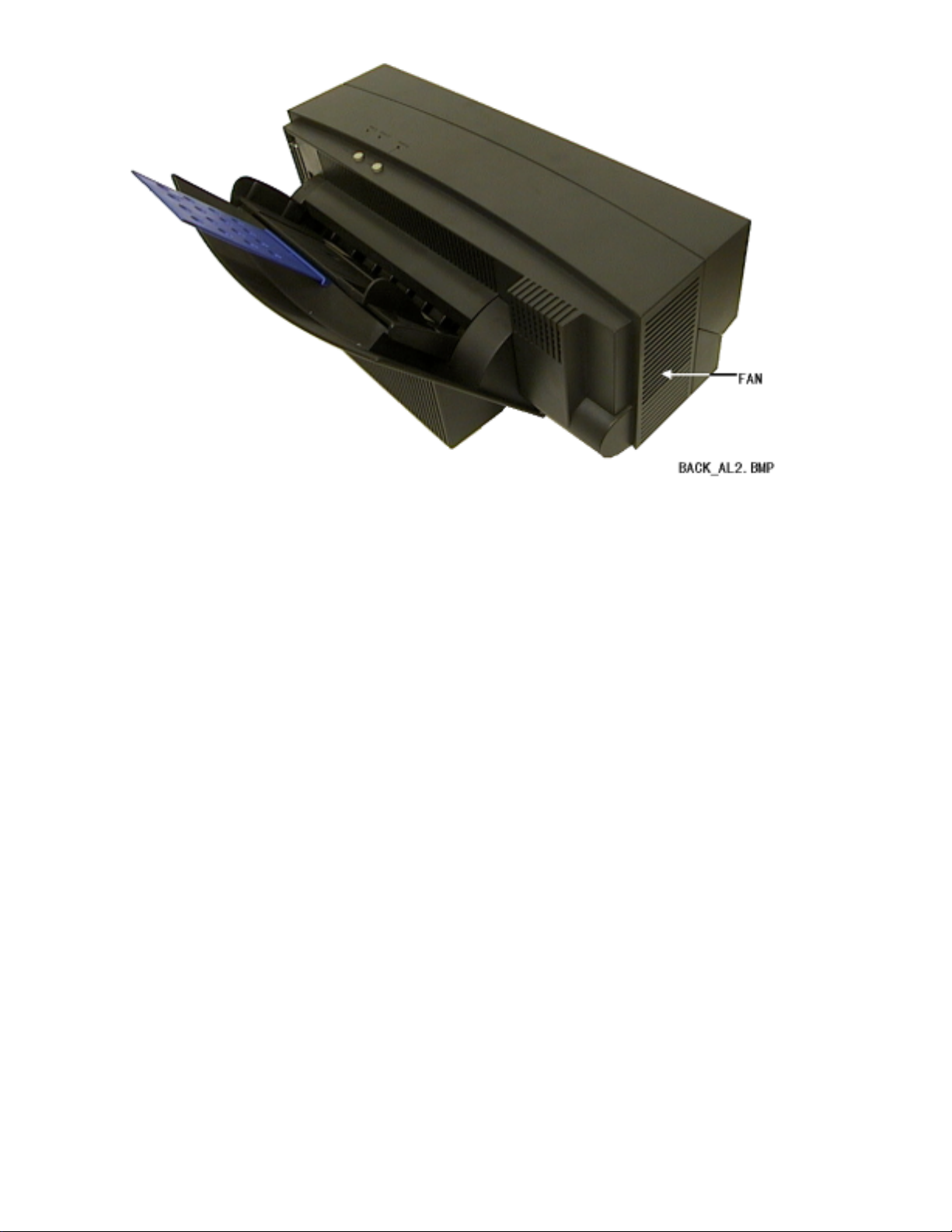
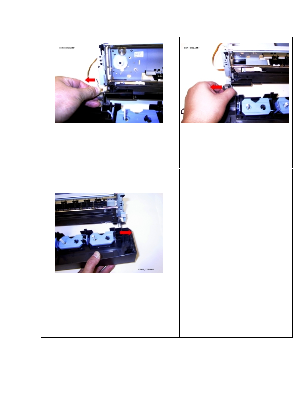
2.3 Detaching of FAN
R
R
t
3.P
t
1
emove the screws in the place of t h e arrows
1 and 2.
.
2.4 Detaching of Carriage_Unit
1
emove the Washer (for Main_Shaft) with
weezers in the place of the arr ows 1, 2 and
2
ull out the Main_Shaft in the direction of
he arrow.
9/71
Page 12
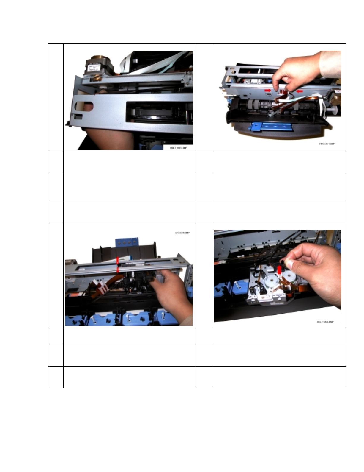
3
T
P
r
a
s
L
o
T
d
4
ake off the CR_Belt from Drive_Pulley.
5 6
ift up and pull out the Carriage from inside
f Frame_Unit.
ush the snap in the place of the arrow and
emove the FPC_Holder from Frame_Assy
nd then move the FPC to Carriage_Unit
ide.
ake off the CR_Belt from Carriage in the
irection of the arrow.
10/71
Page 13
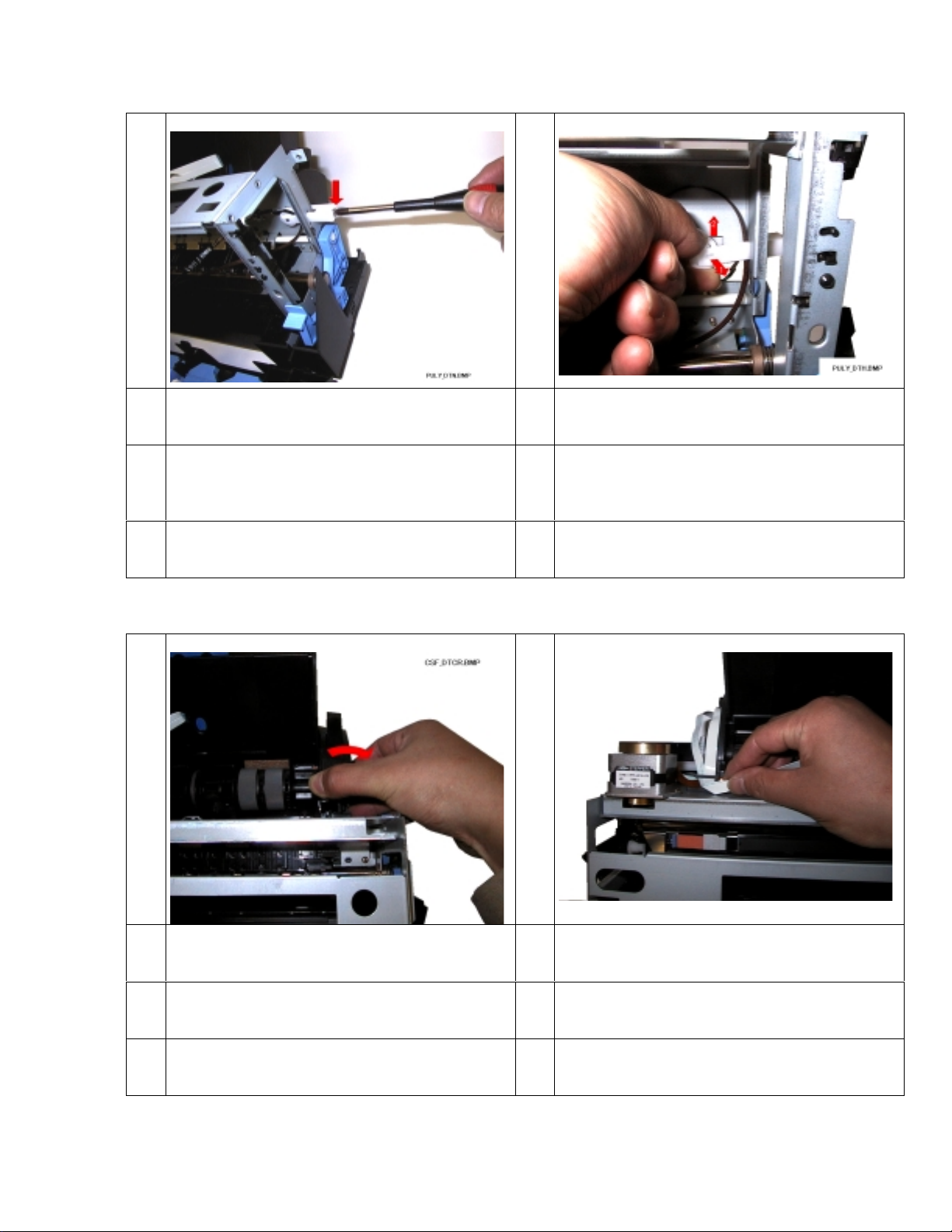
2.5 Detaching of Sub_Pulley
R
o
t
S
d
S
r
R
a
R
F
1
emove the Pulley_Base_Shaft in the place
f the arrow with screwdriver. And remove
he Belt_Spring.
2.6 Detaching of Mechanism
2
pread the points of Pulley_Base in the
irection of arrow 1 and remove the
ub_Pulley to the direction of arrow 2. And
emove the CR_Belt.
1
emove the CSF_Cover_R in the direct ion of
rrow.
2
emove the Three FPC(DC Tape,frame
PC,and CR motor cable).
11/71
Page 14
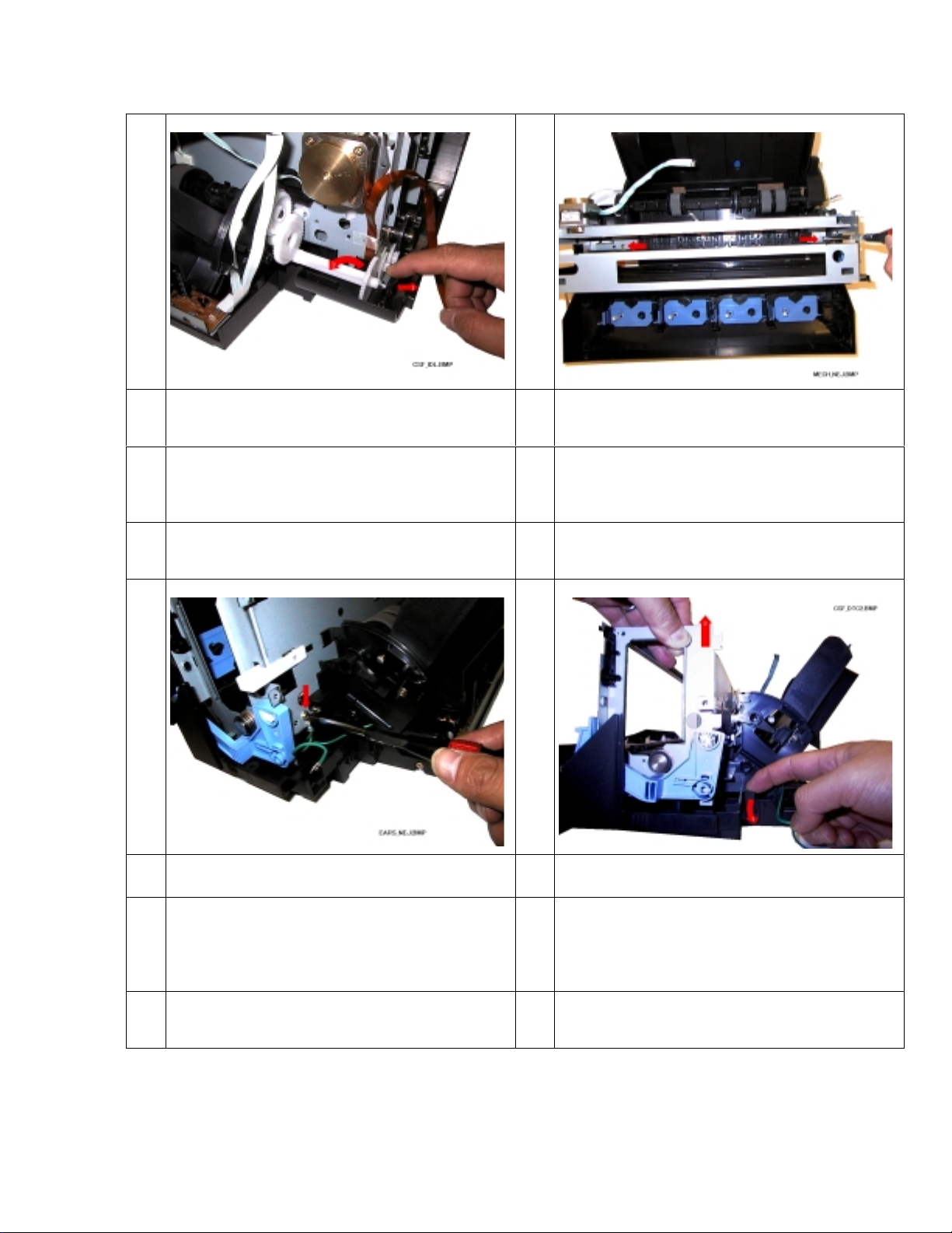
3
P
d
C
2.R
t
R
o
P
d
M
a
D
4
ull the point of L_Cover_Assy in the
irection of the arrow 1 and remove the
SF_Idle_Gear in the direction of the arrow
5 6
emove the screw (M3*L6BIN D) in the place
f the arrow.
emove the screws (M3*L 10P) in the plac e of
he arrows 1 and 2.
ull the point of L_Cover_Assy in the
irection of the arrow 1 and lift up the
echanism a little in the direction of the
rrow 2.
o same procedur e on each side.
12/71
Page 15
7
L
r
R
t
R
a
ift up in the direction of the arrows and
emove the Mechanism.
2.7 Detaching of CSF_Unit
1
emove the screws (M3*L 6TP) in the plac e of
he arrows 1 and 2.
2
emove the CSF_Unit in the direction of the
rrow.
13/71
Page 16
2.8 Detaching of Front_Cover_Unit
R
F
R
f
a
R
f
a
1
emove the Damper_Spring from
rame_Unit in the direction of the arrow.
2
emove the left side of Front_Cover_Unit
rom Frame_Unit in the direction of the
rrow.
3
emove the right side of Front_Cover_Unit
rom Frame_Unit in the direction of the
rrow.
14/71
Page 17
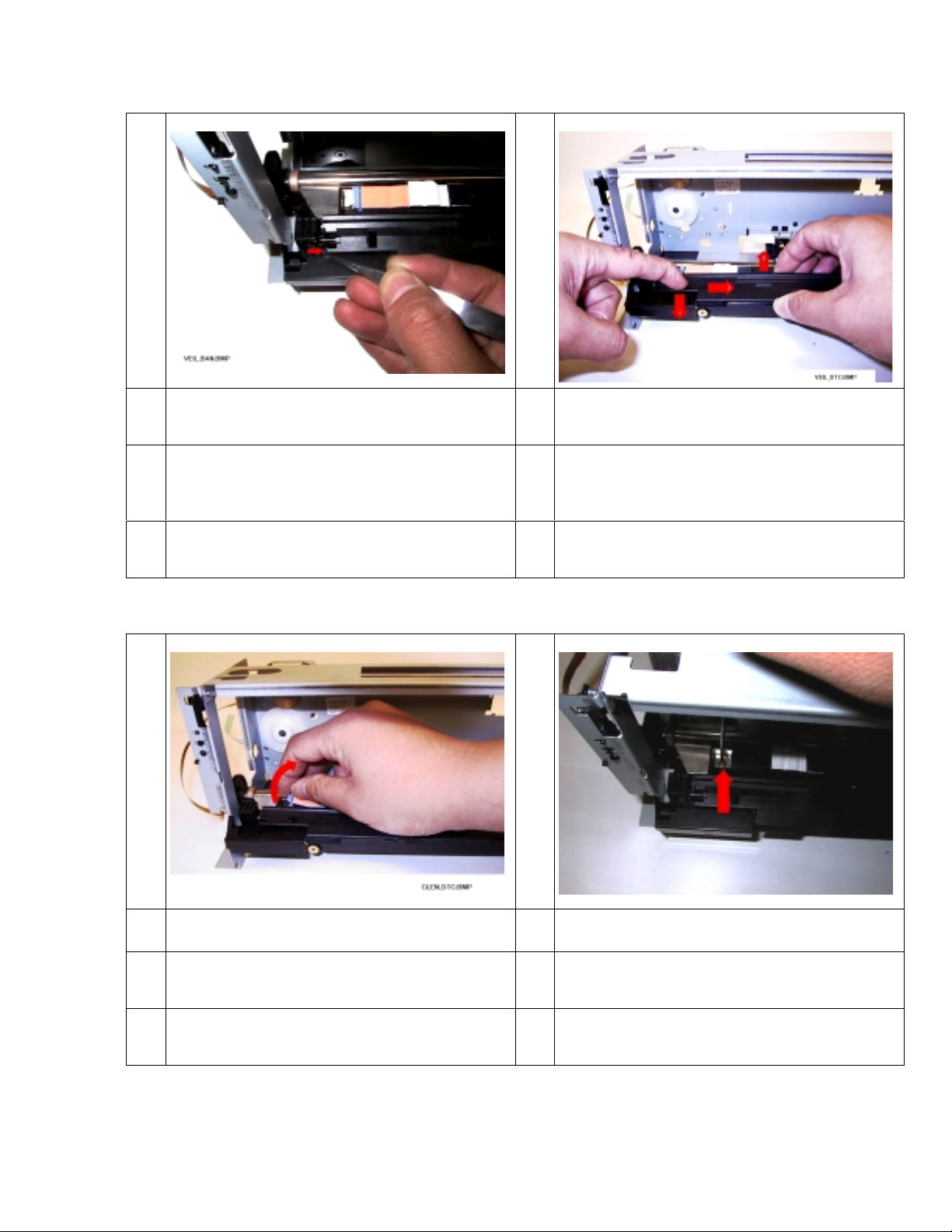
2.9 Detaching of Veil_Unit
P
o
(
)
P
i
V
u
R
F
R
w
1
lace the leg of the Veil_Spring in the hooks
n the Veil_Unit.
To prevent the Spring being lost.
2.10 Detaching of Platen
2
ush the projection in the hole of Veil_Unit
n the direction of arrow 1 and shift
eil_Unit in the direction of arrow 2. And lift
p and remove it in the direct ion of arrow 3.
1
emove Cleaning-Pad_Dye-Sub from
rame_Unit in the direction of the arrow.
2
emove the screw in the place of the arrow
ith screwdriver.
15/71
Page 18
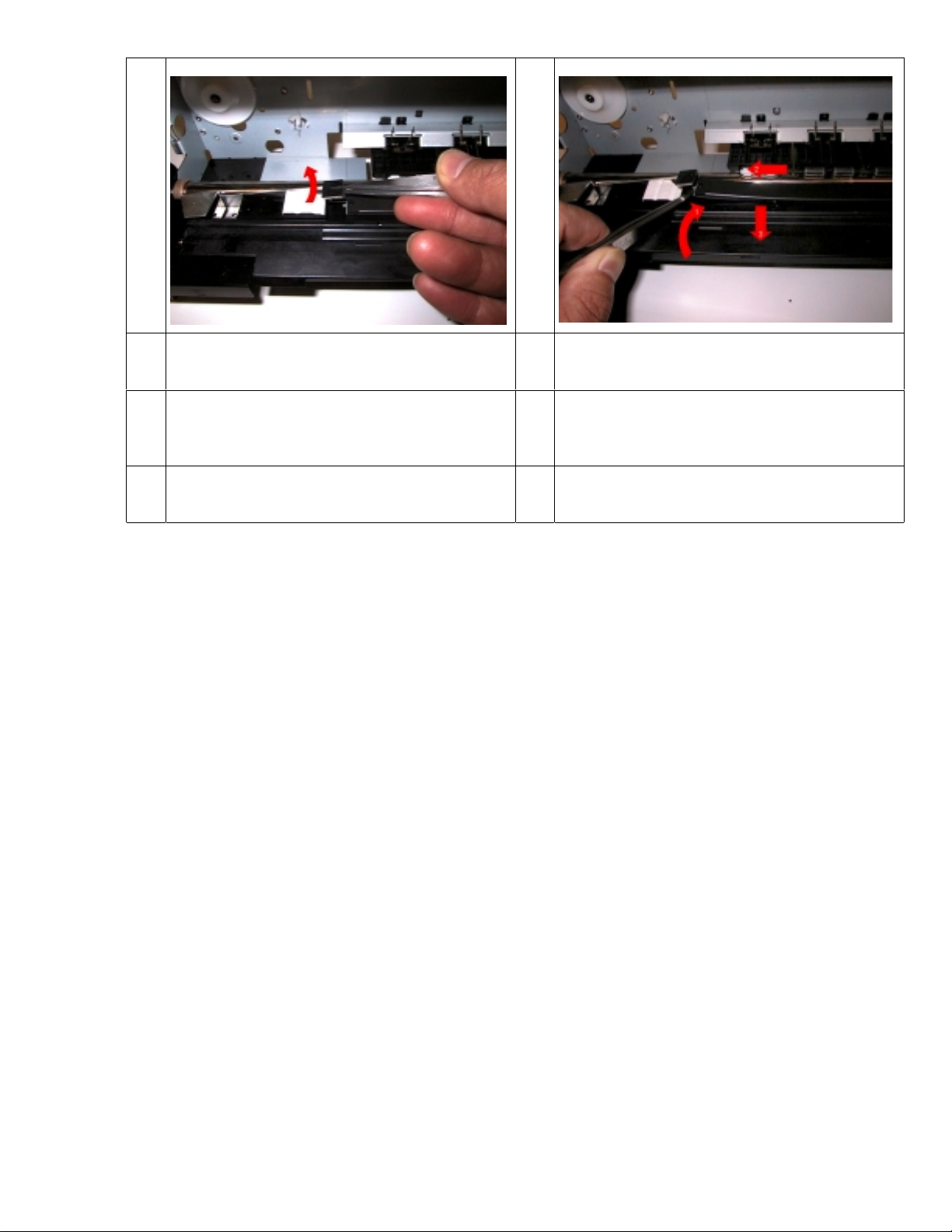
3
L
a
L
a
t
d
4
ift up the heat sink in the direction of the
rrow.
ift up the Platen in the direction of the
rrow 1 and shift Platen in the direction of
he arrow 2. And lift up and remove it in the
irection of the arrow 3.
16/71
Page 19
2.11 Detaching of Cleaning_Pad
L
S
T
d
R
p
D
L
d
t
1
ift up and remove the Cleaning_Pad_Dyeub in the direction of the arrow.
2.12 Detaching of Power_Supply
2
ake and remove the Cleaning_Pad in the
irection of the arrow.
1
emove the screws (1,2-M3*L6BIND) in the
lace of the arr ows 1 and 2. And take off t he
C_Cable in the place of t h e arrow 3.
2
ift up and shift the Power_Supply in the
irection of the arrows 1, 2 and remove it in
he direction of the arrow 3.
17/71
Page 20
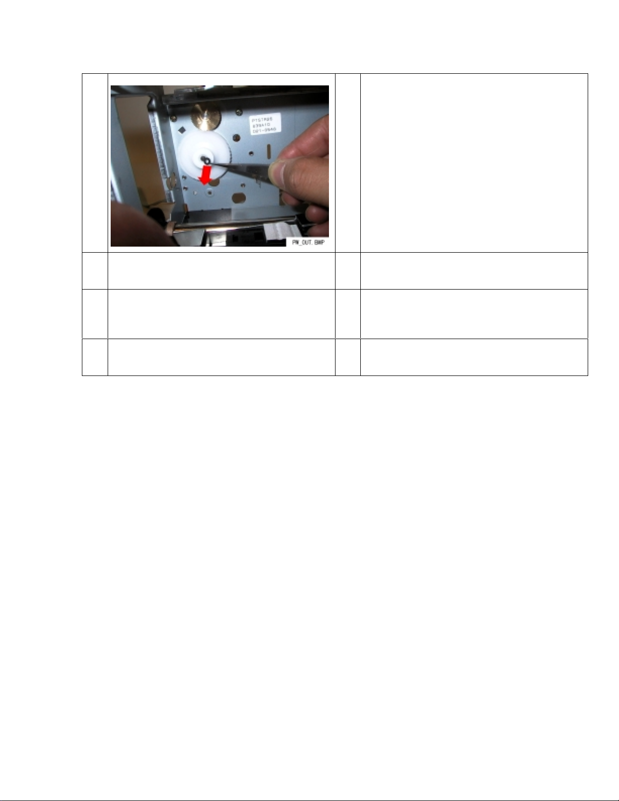
2.13 Detaching of CR_Drive_Pulley
R
P
P
1
emove the CR_Drive_Pulley and
ulley_Flange after removing the Washer (f or
ulley) as shown.
18/71
Page 21
Chapter 3: Assembly
I
t
s
P
d
I
p
D
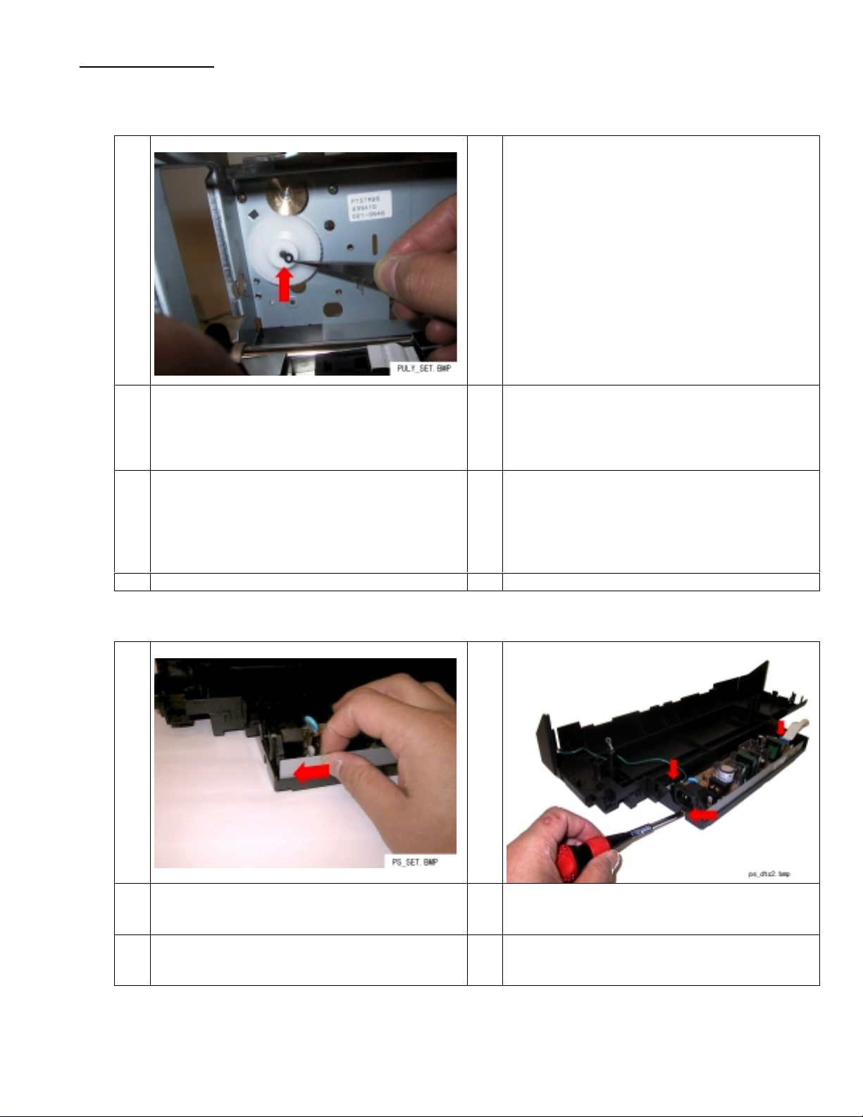
3.1 Installing of CR_Drive_Pulley
1
nstall the Washer (for pulley) after installing
he CR_Drive_Pulley and Pulley_Flange as
hown.
The removed Washer(for pulley) cannot be
Reused once. Use the new art i cle.
3.2 Installing of Power_Supply
1
2
ut the Power_Supply in and shift it in the
irection of the arrow.
nstall the screws (1,2-M3*L6BIND) in the
lace of the arr ows 1 and 2. And insert t he
C_Cable in the place of t h e arrow 3.
19/71
Page 22
3.3 Installing of Cleaning_pad
S
t
P
t
P
P
N
a
1
tick the Cleaning_Pad in the area shown in
he direction of the arrow.
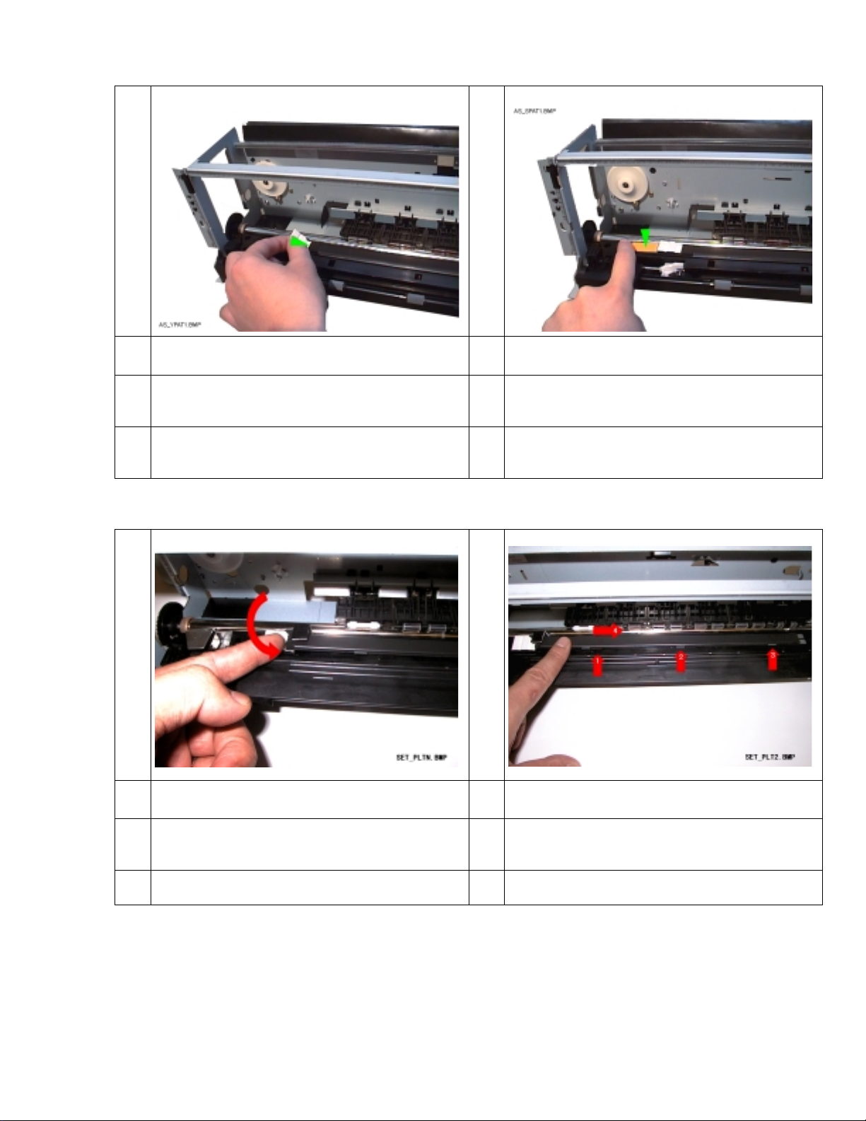
3.4 Installing of Platen
2
ut and push the Cleaning_Pad_Dye-Sub in
he direction of the arrow until clicks.
1
ut the Platen under the heat sink.
2
ut the Platen under the projection of No.1-
o.3 doing the slide in the direction of the
rrow (No.4).
20/71
Page 23
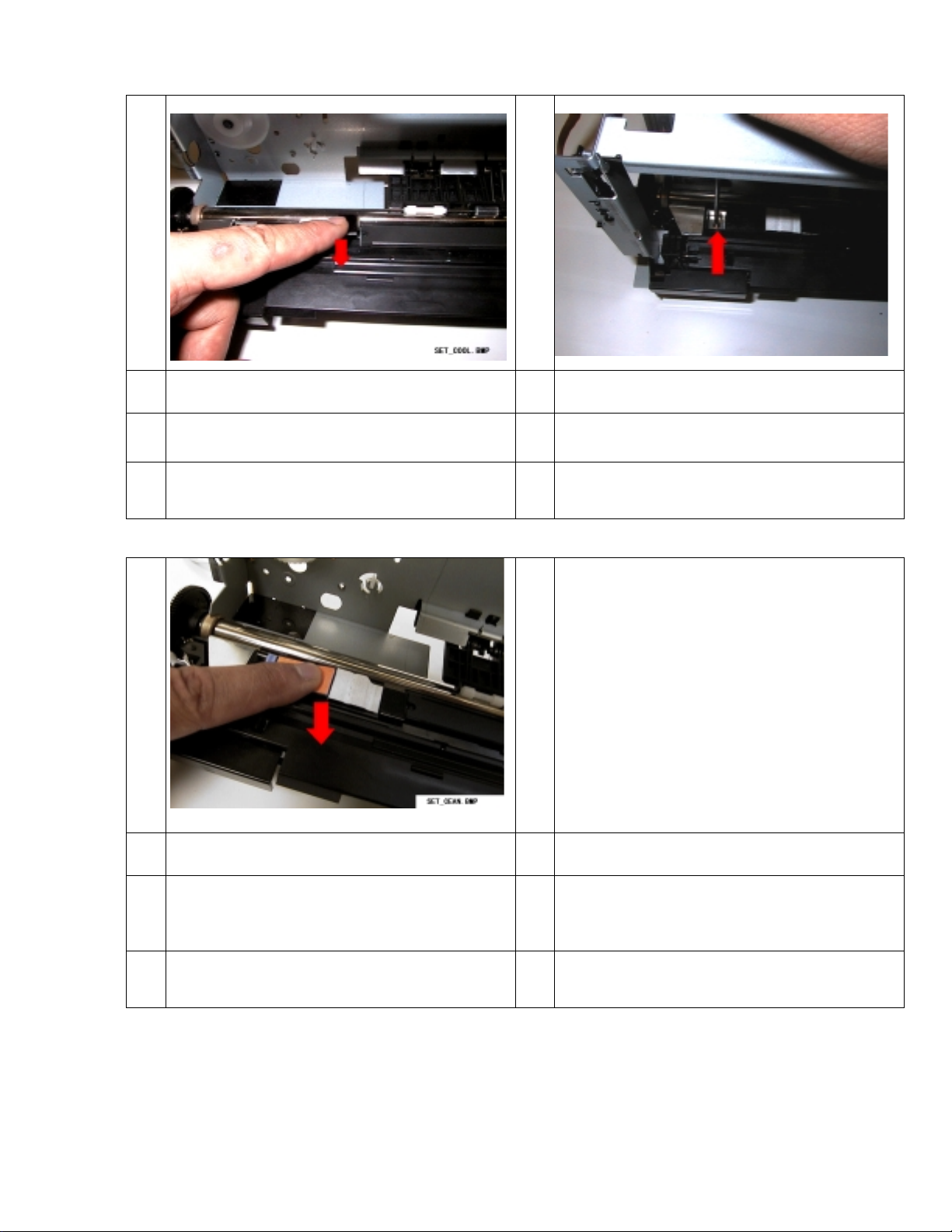
3
P
a
T
P
d
ush the cooling pad in the direction of the
rrow.
ighten the screw in the place of th e ar r ow.
ush the Cleaning_Pad_Dye-Sub in the
irection of the arrow.
21/71
Page 24

3.5 Installing of Veil_Unit
I
V
I
i
1
nstall the Veil_Spring on left side of the
eil_Unit as shown.
2
nsert the point of right side of the Veil_Unit
n the hole at the place of the arrow.
22/71
Page 25

3
I
i
proj
p
T
V
D
4
nstall the point of the left side of Veil_Unit
n the place of the arrow 1 and install the
ection in the hole of Veil_Unit by
ushing the place of the arr ow 2.
5
ake off this side leg of Veil_Spring from
eil_Unit.
etail after installing.
23/71
Page 26

3.6 Installing of Front_Cover_Unit
I
F
I
F
nstall right side of the Front_Cover_Unit to
rame_Unit.
nstall left side of the Front_Cover_Unit to
rame_Unit.
24/71
Page 27

H
b
I
a
I
a
a
ung the point of Dumper_Spring on the
ehind the Frame_Unit.
3.7 Installing of CSF_Unit
1
nstall the CSF_Unit in the direction of the
rrow.
2
nstall the screw(M3*L6TP) while push down
gainst the CSF_Unit in the place of the
rrow.
25/71
Page 28

3
I
a
a
C
F
C
F
4
nstall the screw(M3*L6TP) while push down
gainst the CSF_Unit in the place of the
rrow.
5
heck no opening between CSF_Unit and
rame_Unit in the direction of arrow.
heck no opening between CSF_Unit and
rame_Unit in the direction of arrow.
26/71
Page 29

3.8 Installing of Mechanism
P
Adj
proj
a
C
a
o
D
1
ut the Mechanism on the L_Cover _Assy.
3 4
2
ust two holes of Frame_Unit and
ections of L_cover_Assy in the place of
rrow.
heck installation point of L_Cover_Assy
nd CSF_Unit in the place of the arrow. Pull
ut the FG_Cable as show n.
o same procedur e on each side.
27/71
Page 30

5
I
t
C
m
t
P
a
t
L
I
s
6
nstall the screws(M3*L10P) in the place of
he arrows 1 and 2.
7 8
lamp the FPC (the upper part)and CR
otor-cable(the lower side) in the place of
he arrow.
ut the CSF_Idle_Gear in the place of the
rrow 1 and push down it in the direct ion of
he arrow 2 and install it into the point of
_Cover_Assy.
nstall the PS_Lever to CSF_Cover_R as
hown.
28/71
Page 31

9
I
P
t
C
a
t
10
nstall the CSF_Cover_R while pushing the
S_Lever in the direction of “A”. Next,hung
he FG_cable on the gate of CSF_Cover_R.
lose the CSF_Cover_R in the place of the
rrow and install the FG_Cable(arrow 1) with
he screws.(M3*L6BIND).
29/71
Page 32

3.9 Installing of Sub_Pulley
I
S
B
I
s
I
S
s
S
t
1
nstall the Pulley_Base to Frame_Unit with
ub_Pulley_Shaft after inserting the
elt_Spring in the place of the arr ow 1.
2
nstall the CR_Belt and Sub_Pulley as
hown.
3 4
nstall Sub_Pulley, Sub_Pulley_Flange and
ub_Pulley_Shaft in the disposition as
hown.
pread the points of Pulley_Base and insert
hese parts.
30/71
Page 33

3.10 Installing of Carriage_Unit
H
t
t
C
i
1
old the CR_Belt while kee ping the teeth to
his side. And into the place of the arrow on
he Carriage.
2
omplete installation of CR_Belt (pushed
nto the iterior)to Carriage as shown.
31/71
Page 34

3
I
I
o
t
I
C
I
p
4
nstall the CR_Belt on the CR_Drive_P ulley.
5 6
nsert the Main_Shaft into Frame_Unit and
arriage in the direction of the ar r ow.
nstall the Carriage on the Frame_ Unit after
pening each Cariage_Stopper in the place of
he arrows.
nstall the Washer(for Main_Shaft) in the
lace of the arrows 1, 2 and 3 with tweezers.
32/71
Page 35

7
M
t
H
a
i
a
P
a
i
I
s
8
ove the FPC behind of the Frame_Unit
hrough the hole of the place of t he arrow.
3.11 Installing of Main_PCB
1
ook the FPC_Holder in the place of the
rrows 1 and 2 on the Frame_Unit and
nstall the snap in the place of the arr ows 3
nd 4 by pushing.
2
ut the Main_PCB in the place as shown
nd install one harnesses and three FPC’s
nto these connectors.
nsert the screwdriver through a hole of
hown.
33/71
Page 36

3
I
a
s
I
M
a
a
I
I
4
nstall the screw(L3*L6TP) in t he place of t he
rrow. Next, two FP C is fixed by clampi ng as
hown in Figure.
nstall the screws(1,2-M3*L12,3-
3*L6BIND) in the place of the arr ows 1 ,2
nd 3 after putting the I/F_Plate in the place
s shown.
nstall the DC_Tape as shown in th e f i gur e.
nstall the DC_Tape as shown in th e f i gur e.
34/71
Page 37

3.13 Installing of Cases
P
F
I
P
u
P
I
s
B
a
1
ut the U_Cover_Assy on as shown with
ront_Cover_Unit opened. Then pull out the
nterface_Lock from U_Co ver_Assy.
2
ush down each side of the U_Cover_Assy
ntil clicks. At this time, put the edge of the
aper_Guide in U_cover_Assy.
3 4
nstall the FAN-Cable and DC_Tape as
hown in the figure.
uilt CSF_cover_L into the direction of the
rrow.
35/71
Page 38

5
I
a
b
I
t
2
3
4
nstall the Rear_Cover in the dir ection of the
rrow. Check that there are no openings
etween CSF_Unit and Rear_C over.
3.14 Lubrication
1
nstall the screw (M3*L10P) in the place of
he arrows 1, 2 and 3.
2
1-Frame(both side of rail):EM60L
-Main_Shaft:EM50L T-6
-Drive_Pulley_Shaft:T-6
-Sub_Pulley_Shaft:EM50L
1,2,3-LF_Idle_Gear’s:EM60L
36/71
Page 39

Chapter 4: Adjustments, Printing test
4.1 Upper an d l ower light and shade adjustments for 60 0 dpi print mode.
When something wrong is found in the print inspection, the following work is done.
1) Connect the printer cable to the printer and turn it on.
2) Start the program of \TOOL\W26_EDIT.EXE.
3) 10. Bank8 1/2 is sel ected with the cursor key.
4) The data of 30 bytes is manually adjusted respectively of Cyan (Fut ure C), Magenta (Future M),
Yellow (Future Y), and Black (Future B) about 600dpi print.
The first numerical value corresponds to one byte of the print head on. The last numerical Value
corresponds at a last one byte. The densit y can be adjusted by adding and subtracting (+10 shade
37/71
Page 40

10 light ) the numerical value every 30 blocks. Adjust the values of the references to the print
result.
5) Press F10 to return ba ck and pr ess F1 to wr ite to EEP_R OM. Press F1 0 and start “22.Q uit“
for finishing
the light and shade adjustments. The print inspection is repeated an d if something wr ong is
found in the
light and shade of the doing print, this work is repeated.
4.2 Upper and lower light and shade adjustments for “Vphoto Print with Vphoto Primer (Future
Primer)” mode.
This needs to use the color scanner EPS ON GT-9500 and some ph oto retouch soft wear(EPSON
SCAN Photo SHOP etc. ). The OS must be Win3.1.
Do following adjustments after f inishing Head voltage adjustments.
(1) Starting \SCANER\PT_100.BAT prints the adjustment pattern.
(2) The print result is read with full color scanner (300dpi).
Store the result of reading in the same directory as \SCANER\PT_100.BAT.
Assume the file name to be 101.BMP always when you store it.
About notes when EPSON SCAN is used
When the data is pr eserved with this software, the number of 01 is automatically added
behind the file
name. Therefore, it should be specified 1.BMP when specifyin g for 101.BMP.
3) \SCANER\CLC_100.BAT is started.
The calculation of the light and shade adjustment is aut omatically begun. The result is
written in EEP-•
ROM.
(4) (1) - (3) is repeated twice.
Refer to the attached paper for setting the scanner. Start \SCANER\W26BKD10.EXE to
return the content
of the light and shade adjustment to an initial value.
4.3 Upper and lower light and shade adjustments for “Vphoto Print with Vphoto Print Film”
mode.
38/71
Page 41

This needs to use the color scanner EPS ON GT-9500 and some ph oto retouch soft wear(EPSON
SCAN Photo SHOP etc. ). The OS must be Win3.1.
Do following adjustments after f inishing Head voltage adjustments.
(1) Starting \SCANER\PT_50.BAT prints the adjustment pattern.
(2) The print result is read with full color scanner (300dpi).
Store the result of reading in the same director y as \SCANER\PT_50.BAT.
Assume the file name to be 101.BMP always when you store it.
About notes when EPSON SCAN is used
When the data is preserved with this software, the number of 01 is automatically added
behind the file
name. Therefore, it should be specified 1.BMP when specifyin g for 101.BMP.
(3) \SCANER\CLC_50.BAT is started.
The calculation of the light and shade adjustment is automatically begun. The result is
written in EEP ROM.
(4) (1) - (3) is repeated twice.
Refer to the attached paper for setti ng t h e scanner .
Start \SCANER\W26BKD50.EXE to return the content of the light and shade adjustment to
an initial
value.
4.4 Upper and lower light and shade adjustments for “Dye-Sublimation Print (Future Dye-Sub
Print)” mode.
This needs to use the color scanner EPS ON GT-9500 and some ph oto retouch soft wear(EPSON
SCAN Photo SHOP etc. ). The OS must be Win3.1.
The OS must be Win3.1.Do following adjustments after finishing Head voltage adjustments.
(1) Starting \SCANER\PT_DSub.BAT prints the adjustment pattern.
(2) The print result is read with full color scanner (300dpi).
Store the result of reading in the same director y as \SCANER\PT_DSub.BAT.
Assume the file name to be 101.BMP always when you store it.
About notes when EPSON SCAN is used
When the data is preserved with this software, the number of 01 is automatically added
behind the file
name. Therefore, it should be specified 1.BMP when specifyin g for 101.BMP.
39/71
Page 42

(3) \SCANER\CLC_DSub.BAT is started.
The calculation of the light and shade adjustment is automatically begun. The result is
written in EEP ROM.
(4) (1) - (3) is repeated twice.
Refer to the attached paper for setti ng t h e scanner .
Start \SCANER\W26BKDSub.EXE to return the content of the light and shade adjustment to
an initial
value.
Attention
Use the undermentioned card ridg e in the up per and lower light and shade
adjustment According to each
mode.
Upper and lower light and shade adjustments for “Vphoto Print with Primer”
mode.
Use card ridge C M Y B VP Finish (Future F ) Primer
Upper and lower light and shade adjustments for “Vphoto Print with
Vphoto Print Film” mode.
Use card ridge C M Y B F
Upper and low er light and shad e adjustments for “Dye-Sublimation Col or
Print” mode.
Use card ridge Dye-S u blimation Cyan(Future Dye-sub C) Dye-
Sublimation Magenta
(Future Dye-su b M)• Dye-Sublimation Overcoat (Future Dye-sub OC)
( Dye-sub M) Dye-Sublimation Overcoat ( Dye-sub OC)
40/71
Page 43

4.5 Printing test
1) Connect the printer cable to the printer and turn it on.
2) Start the program of \STM32\W26.BAT.
3) Supply each cartridge and each paper to the printer and st ar t printing test.
41/71
Page 44

4) Main menu and Cartridge and Paper.
No. TEST Paper Cartridge
1 Test of OHP Film 600dpi OHP C,M,Y,B
2 Test of High Grade Paper 600dpi HGP C,M,Y,B
3 Test of Post Card 600dpi Card C,M,Y,B
4 Test of Dye-Sub Paper Dsub Dye-
SubC,M,Y,OC
5 Test of Foil print position Card B,Gold Foil
6 Test of Foil Card C,M,Y,B
Gold/Silver Foil
7 Test of Vphoto Color with Primer HGP C,M,Y,B,F,Primer
8 Test of Vphoto Color Vphoto C,M,Y,B,F
9 Test of Vphoto Mono Vphoto B,F
11 Test of High Grad e Paper 600dpi HGP C,M,Y,B
12 Adjust of print position --------- ---------------------
---
13 Test of Dye-Sub Color
Paper(Short)
14 Adjust of Dye-Sub Color Dsub Dye 15 Adjust of (only white line
and black line check)
16 Check Printer tenperature ---------- ------- ------------- 17 Adjust of Vphoto Color Vphoto C,M,Y,B,F
18 Adjust of Vphoto Mono Vphoto C,M,Y,B,F
19 Check ---------- ---------------------
20 Adjust of Vphoto Color LF Vphoto C,M,Y,B,F
21 Adjust of Dye-Sub Color LF -1 --------- ---------------------
22 Adjust of Dye-Sub Color LF +1 ---------- -------------------- 23 Test of Dye-Sub Color Paper(Full) Dsub Dye 27 Test of Vphoto Card Vcard C,M,Y,B,F
29 Check Vphoto C &M Vphoto C,M,Y,B,F
Dsub Dye-
SubC,M,Y,OC
SubC,M,Y,OC
OHP C,M,Y,B
---
---
---
---
SubC,M,Y,OC
Paper types
OHP:OHP Film Dsub: Dye-Sub Paper
HGP: High Grade Paper Vphoto: Vphoto Print Film
Card: Post Card Vcard: Vphoto Card
••
5) Check the working of FAN after taking off and inserting each harness once while printing by
printer driver .
42/71
Page 45

43/71
Page 46

4.6 Explanation of usage of each print mode
No.1-No.9 No.1-No.9 is a usual shipment inspection and an adjustment pattern.
However, No. ,5 is not usually used.
No.11 It is an insp ection pattern of the 600dpi Print of Hi gh Grade Paper.
This does not contain the cartridge change t est.
No.12 It is positioning of the print beginning. It is only input of the numerical value.
No.13 It is a shortening pattern of the Dye-Sub Color inspection. This is used to confirm
something wrong.
No.14 This is used to correct something wrong with the Dye-Sub Color print.
The repair of upper and lower light and shade and a black line and the white line can be
corrected.
No.15 In this item , a w hite line and a black line can be adjusted by t h e OHP print.
However, the numerical value can be only input in this it em.
Please confirm the result of the adjustment (clause of No.1).
No.16 Confirm a tion of temperature of printer
An environmental temperature and the t emperature of the head can be confirmed.
This item is not usually used.
No.17 It is a manual upper and lower light and shade adjustment of th e Vphoto Color.
Please confirm the state of the print r esult and select the best adjustment item.
No.18 It is a manual upper and lower light and shade adjustment of th e Vphoto Mono.
Please confirm the state of the print r esult and select the best adjustment item.
No.19 It is for the confirmat ion of fan operation. The fan works when this it em is selected.
The operation stops to come off this item.
44/71
Page 47

No.20 It is LF adjustment of the Vphoto Color. Please ch oose the best item seeing the print result.
No.21 It is LF adjustment of the Dye-Sub color print. The pa per feed ste p doe s aut omati cally w hen
this
item is Selected and –1( contract)is done. However, the numerical value is only input in this
item.
Please confirm the result of the adjustment (clause of No.4).
No.22 It is LF adjustment of the Dye-Sub color print. The pa per feed ste p doe s aut omati cally w hen
this
item is Selected and +1(extend) is done. However, the numerical value is only input in this
item.
Please confirm the result of th e adjustment (clause of No.4).
No.23 It is a A4 full pattern of the Dye-Sub Color inspection. This is not usually used.
No.27 It is a postcard inspection pattern of the Vphoto Color. This is not usually used.
No.29 Cyan and magenta of the Vphoto color are printed dividing. When light and shade is
adjusted,
each state can be confirmed. It is convenient to judge the adjustment method.
45/71
Page 48

4.7 Method of adjusting light and shade without using scanner.
Or, the method of adjusting the manual when light and shade cannot be adjusted with the
scanner.
(1) Connect the printer cable to the printer and turn it on.
(2) Start the program of \TOOL\W26_EDIT. EXE.
The light and shade adjustment data of each print mode is stored in an under mentioned item.
If you need the manual adjustment, the adju stment be comes po ssible by r ewrit ing these num er ical
values.
10.Bank8 ½ PPC C/PP C M/PPC Y/PPC K
The 600dpi light and shade adjustment data
8.Bank7[1/2] • SUBLIMATE C/ SUBLIMA TE M/ SUBLIMATE Y
Dye-Sub Color prints light and shade adjustment data
VARY 100co C/ VARY 100co M/ VARY 100co Y/ VARY 100co K
Vphoto Color prints with Vphoto Print Film light and shade adjustment data
VATY50mo
Vphoto Mono prints with Vphoto Print Film light and shade adjustment data
8.Bank7[2/2] UP+VARYco C/ UP+VARYco M/ UP+VARYco Y/ UP+VARYco K/
Vphoto Color prints with Primer light and shade adjustment data
46/71
Page 49

UP+VATYmo
Vphoto Mono prints with Primer light and shade adjustment data
47/71
Page 50

Chapter 5: Maintenance
5.1 Cleaning
5.1.1 Cleaning of exterior
Use a soft cloth moistened with alcohol or watered neutrality clean ser (if necessary) to clean the exterior .
Do not use any other chemicals (s uch as t h inner ) as these may damage the plastic.
5.1.2 Cleaning of inside
Use a vacuum cleaner (if necessary) t o r emov e dust.
5.1.3 Cleaning of Print_Head
1) Turn off the power. Remove the power cord from the power inlet.
2) Open the Front_Cover_Unit and wipe the Print_Head lightly with a cotton swab moistened with alcohol
(if necessary).
3) Do a print test and check the print quality.
Caution: Do not touch the sur f ace of Platen with the alcohol cotton swab.
47/71
Page 51

5.1.4 Cleaning of Platen
1) Turn off the power. Remove the power cord from the power inlet.
2) Open the Front_Cover_Unit.
3) Affix cellophane tapes to the Platen and rub it lightly.
4) Remove the tape.
5) Repeated the 3 and 4 until becomes the Platen is cl ean.
6) Do a print test and check the print quality.
Caution: Do not place tape on the Cleaning_Pad be cause the pad may peel off and cause the printer to
malfunction.
48/71
Page 52

5.1.5 Cleaning of CSF_Unit
1) Turn off the power. Remove the power cord from the power inlet.
2) Remove the U_Cover_Assy.
3) Wipe the rubber roller with a damp cotton swab.
4) Install the U_Cover_Assy.
5) Check the paper feeding operati on .
Caution: Do not use an exces sively wet cotton swab. The water may dr op on ot her components causing
damage to the printer.
49/71
Page 53

Chapter 6: Trouble shooting
1. Power
Problem Cause Action
Connector is not prop er ly inserted. Check CN1 (Main_PCB).
Check the connector of Power_Supply
DC_Cable is broken off . Replace the DC_Cable.
No Power
Power is turned on but
Carriage does not
function.
Blown Fuse. Replace the Power_Supply and adjust
head voltage.
No DC power. Replace the Power_Supply and adjust
head voltage.
Main_PCB is missing Replace the Main_PCB and return the
EEP_ROM.
Connector is not prop erly inserted. Check CN5, 6 (Main_PCB).
FPC is br oken off. Replace mechanical unit and set each
adjustment.
Main_PCB is missing Replace the Main_PCB and return the
EEP_ROM.
Curl_Motor does not move. Check moving or replace Frame_Unit
and set each adjustment.
UD_Motor does not move.
Bad RC_Sensor.
Replace the Carriage_Unit and set
each adjustment.
50/71
Page 54

2. Pri n ting
Problem Cause Action
Connector is not prop er ly inserted. Check CN4 (Main_PCB).
FPC is broken off. Replace the Carriage_Unit and set
Mechanism moves but
cannot print.
Incorrect head voltage. Check and adjust head volt age.
Main_PCB is missing Replace the Main_PCB and return the
Connector is not prop er ly inserted. Check CN4 (Main_PCB).
each adjustment.
EEP_ROM.
Upper and lower light
and shade.
Vertical constant
stripes.
Inconstant stripe.
Missing dot. Bad Head. Replace the Carriage_Unit and set
Broken ribbon
FPC is broken off. Replace the Carriage_Unit and set
each adjustment.
Miss adjustment. Adjustment of Light and shade.
No oil on the Main_Shaft.
No oil on the Frame_Unit.
CR_Drive_Pulley is missing. Replace the CR_Drive_Pulley.
Some alien substance on the Pl at en. Cleaning or replacing of Platen.
Some alien substance on the Frame
rail.
Connector is not prop er ly inserted. Check CN7, 8(Main_PCB).
FPC is br oken off. Replace mechanical unit and set each
Lubrication
Replace the Frame_Unit and set each
adjustment.
each adjustment.
adjustment.
51/71
Page 55

3. Paper f eed
Problem Cause Action
Veil_Unit is not properly installed. Check or replace the Veil_Unit.
Paper jam
Does not feed paper
4. Cartridge Change
Problem Cause Action
Cartridge change error.
CSF_Unit is not properly installed. Check or replace the CSF_Unit.
Frame_Unit is damaged. Replace Frame_Unit or CSF_Unit and
set each adjustment.
Connector is not prop er ly inserted. Check CN5 (Main_PCB).
Bad PE_Lever or LF_Sensor Replace the Frame_Unit and set each
adjustment.
Bad CSF_Sensor or PE_Sensor Replace the Main_ PCB and return the
EEP_ROM.
Bad Carriage_Uni t.
Detached Cassette_Lever
Cassette_Carrier position
Replace the Carriage_Unit and set
each adjustment.
5. Paper curl correction
Paper curl correction
does not work
properly.
5. Other
Front_Cover opens too
quickly.
Front_cover_Unit is not properly
installed.
Veil_Unit is not properly installed. Check or replace the Veil_Unit.
Dumper_Spring is not properly
installed.
Check or replace the
Front_Cover_Unit.
Adjust the spring.
52/71
Page 56

Chapter 7 Parts List
Illustration
Part’s Number Part’s Name
M03274 Platen 1 25 3
1 M40072 Cleaning_Pad_Dye-Sub 1 25 3
2 M40087 Cleaning_Pad 1 25 3
•••••
Qty
Min Lot LT
1 M10193 CR Drive_Pulley 1 25 3
2 M10177 Pulley_Flange 1 25 3
3 PW0250002 Washer(for Pulley) 1 1,000 3
DM01165 Carriage_Unit
Data File(Floppy Disk)
light and shade Data
middle press Data
head voltage Data
130 10
EM2652C.DOC 53/71
Page 57

Illustration
Part’s Number Part’s Name
1 M06701 Main_Shaft 1 25 3
2 PW1100002 Washer(for Main_Shaft) 3 1,000 3
DM01158 Veil Unit 1 25 10
M31608 Veil Spring 1 50 3
Qty
Min Lot LT
DM01170 Front_Cover_Unit
• (with Damper spring)
1 DM01146 CSF_Unit 1 25 6
125 6
EM2652C.DOC 54/71
Page 58

Illustration
Part’s Number Part’s Name
M05354A Paper_Holder_Assy 1 25 3
1 M05356 Holder_Base 1 25 3
2 M05355 Paper_Holder 1 25 3
3 M05354 Card_Stopper 1 25 3
TM26A03BX Main_PCB 1 25 10
M73051 Power_Supply 1 25 10
Qty
Min Lot LT
1 M66154 DC Tape 1 25 6
2 DQC10034A0 Ferite Core 1 25 3
3 M68003 Binder 1 25 3
4 PEB01025AA Cramp 1 25 3
EM2652C.DOC 55/71
Page 59

Illustration
Part’s Number Part’s Name
DM01154 Frame_Unit
Data File(Floppy Disk)
LF Adjustment Data
1 M06648 Sub_Pulley_Shaft 1 25 3
2 M10181 Sub_Pulley 1 25 3
3 M10180 Sub_Pulley_Frange 1 25 3
4 M31612 Belt_Spring 1 25 3
5 M07399 Pulley_Base 1 25 3
6 M06642 Pulley_Base_Shaft 1 25 3
Qty
110 10
Min Lot LT
M02412A L_Cover_Assy 1 10 3
EM2652C.DOC 56/71
Page 60

Illustration
Part’s Number Part’s Name
M02417 Rear_Cover 1 10 3
1 M02418 CSF_Cover_L 1 50 3
2 M02414 CSF_Cover_R 1 50 3
3 M13286 PS_Lever 1 15 3
M02453A U_Cover_Assy 1 10 6
Qty
Min Lot LT
M11499 CSF_Idle_Gear 1 25 3
M61004 FAN 1 25 3
EM2652C.DOC 57/71
Page 61

Illustration
Part’s Number Part’s Name
1 S01300100 M3*L12 S c rew 2 5,000 3
2 S03300002 M3*L6BIND Screw 4 4,000 3
3 S95300011 M3*L6TP Screw 3 4,000 3
4 S93300004 M3*L10P Screw 5 4,000 3
M66153 FG_Cable_2 1 25 8
M07388 I/F_Plate 1 25 3
1 M92717 CR_Stopper 1 25 3
Qty
Min Lot LT
2 M92676 CarriagePackingMaterial 1 50 3
M92668A Packing_Unit 1 25 3
M92726A Cushion Assy 1 25 3
EM2652C.DOC 58/71
Page 62

Illustration
Reference Material
Grease
Part’s Number Part’s Name
M92611 Packing Box 1 25 3
Manufacture Dow Corning
Product Name Moricoat EM60L
Manufacture Dow Corning
Product Name Moricoat EM50L
Qty
Min Lot LT
Oil
Manufacture Kanto Chemical Industry
Product Name Froil T-6
EM2652C.DOC 59/71
Page 63

Chapter 8 Exchang i n g parts
Refer to Chapter 2 and Ch apter 3 for t he exchange proc edures of parts. Inspect and adj ust un der menti oned
content after exchanging parts.
Exchange Parts Head voltage
adjustment
Platen - - X OOXOXOOOO
CR Drive Pulley - - - ---O----Carriage Unit O O O OOXOXOOOO
Veil Unit - - - OOXOXOOOO
Front Cover Unit - - - -O------CSF Unit - - - OOXOXOOOO
Main PCB(return EEP) O X X OOXOXOOOO
Power Supply Unit O - X OOXOXOOOO
Frame Unit - O X OOXOXOOOO
L Cover Assy - - - OOXOXOOOO
Paper feed(LF)
/middle press
Install
Light and
Shade
Adjustment
Print test menu No.
123456789
- : Don’t care
O : Do Test or Adjustment
X : Do if it is necessary.
60/71
Page 64

8.1 Various adjustment met h ods when parts are exchanged
8.1.1 Carriage_Unit
When the carriage unit is exchanged, the following adjustments are necessary.
Input of the light and shade adjustment data
Voltage adjustment of power supply unit
Voltage adjustment of MAIN-PCB
Please do the following procedures after exchanging the carriage unit.
(1) Please install a special connector at a MAIN-PCB and the voltag e t est er.
(2) Please connect the comput er and the printer.
Please start special software. [\TOOL\W26TOOL.BAT]
• (3) Wr ite the content of the floppy disk ap pended to a new carriage unit in the pr inter.
Please set the floppy disk in the computer and select menu number 3.
Please work according to the display. The number is described on the flop py disk.
61/71
Page 65

(4) Please select menus number 5 be cause the voltage is adjusted.
(5) Adjustment of normal voltage
Please adjust the voltage of the power supply to the voltage di splayed on the screen.
(6) Adjustment of Dye-Sub voltage
Please adjust the power supply with the voltage of main PCB within the range of the voltage that the
screen
was displayed.
!(6)
62/71
Page 66

(7) Please input the value which the volt age tester indicates because it is displayed on the screen as "In put
HD-Voltage [1]". This display exists to [1]-[5]. *Voltage tester is PCB-Voltage
(8) HD-Voltage[DSub]
HD-Voltage[DSubOP1]
HD-Voltage[DSubOP2]
HD-Voltage[VD50cps]
HD-Voltage[VDOP4]
Each above-mentioned voltage is displayed on the screen.
Please confirm be the same as the value, which t he voltage tester indicates.
(9) Please do necessary adjust and the pr int tests.
!(8)
63/71
Page 67

8.1.2 Power supply
(1) Please install a special connector at a MAIN-PCB and the voltag e t est er.
(2) Do clause (4) - (9) in clause 8.1.1 aft er exchanging the power supply.
8.1.3 MAIN-PCB
When the MAIN-PCB is exchanged, the f ollowing adjustments are necessary.
Replacement of various the data
Voltage adjustment of power supply unit
Voltage adjustment of MAIN-PCB
8.1.3.1 If the error lamp does not bli n k
(1) Please connect the comput er and the printer.
Please start special software. [\TOOL\W26TOOL.BAT]
(2) The data of EEP-ROM is read from old PCB to the computer.
Please set the floppy disk in the com p uter and select menu 1.
Please work according to the display. Please inp ut the arbitrary number.
(3) Please exchanging MAIN-PCB
(4) Please connect the comput er and the printer.
Please start special softwar e. [ W 26TOOL.BAT ]
64/71
Page 68

(5) The content of former data is written in new MAIN-PCB.
Please set the floppy disk in the computer and select menu number 2.
Please work according to the display. Please Input the same number used in (2).
(6) It is necessary to adjust the voltage. Please do the same w ork as the power supply exchange of cla use
8.1.2.
(9) Please do necessary adjust and the pr int tests.
8.1.3.2 When t he error always occur s
(1) The data cannot be r eplaced.
Please install at NEW-MAIN-PCB detaching EEP-ROM from former MAIN-PCB.
(2) It is necessary to adjust the voltage. Please do the same w ork as the power supply exchange of cla use
8.1.2.
(3) Please do necessary adjust and the pr int tests.
8.1.4 Frame_Unit
(1) Please connect the comput er and the printer.
Please start special softwar e. [\TO OL W 26LFADJ.BAT ]
65/71
Page 69

Explanation of usage of each menu
No.1 After wri ting LF parameter , test printing i n 600dpi mode.
No.5 Test printing in 600dpi mode.
No.6 Widen 1 step line feed, and test printing in 600dpi mode.
No.7 Shorten 1 step line feed, and test printing in 600dpi mode.
(2) Write the content of the f l oppy disk appended to a new Frame_U nit in the printer.
Please set the floppy disk in the computer and select menu number 1.
Please work according to the display. Th e n umber is describe d on the floppy disk.
And test printing at the last.
(3) Please confirm the state of t h e t est print result and select the best adjust ment item (menu No6, 7).
(4) Please do necessary adjust and t h e print tests.
66/71
Page 70

67/71
Page 71

Chapter 9: Software
9.1 Content of software
The following content is included in appended CD.
Empty capacity of the hard disk is a bo ut 500 MB necessary.
Please cancel Read_Only attribute, af t er copying these data (\STM32,\SCANR,\TOOL) to C drive.
(1) \STM32
Print inspection pattern for maintenance
Edit software of EEP-ROM [W26_edit.exe]
Please install this data at C drive.
(2) \SCANER
Software, which relates to scanner for upper and lower light and shade adjustment.
The operating system must use “Win3.1".
Please install this data at C drive.
(3) \TOOL
Software for maintenance• W26TOOL.BAT•
Software of EEP-ROM is Read and Write•
Software of HD-Voltage adjustment
Software for LF Parameter setup W26LFADJ.BAT
Please install this data at C drive.
(4) \MANU_BMP
It is the bit map data used when the maintenance manual is made.
(5) \PART_BMP
It is the bit map data used when the Part-List is made.
68/71
Page 72

(6) \PRN_DATA
It is the print data of this book. “LP1" It is possible to print with DP-5000 with a tool.
[Example] lp1 file-name. PRN
(7) \DOC
These sentences are described with Microsoft Word“Word97".
69/71
Page 73

9.2 About the range of reading of the data when upper and lower light and shade is adjusted
9.2.1 Upper and l ower light and shad e adjustments for “Vphoto Print with Primer” mode.
Upper and lower light and shade adjustments for “Vphoto Print with Vphoto Print Film” mode.
about
(2inch)
Range of reading
X=Read the width of about 2inches in the vicinity of t h e cent er w i t h in the r ange of t h e pr int.
Y=Read the entire pattern.
9.2.2 Upper and lower light and shad e adjustments for “Dye-Sub Print ” mode.
70/71
Page 74

Range of reading
X=600
Y=2049
71/71
 Loading...