

Page 1

Chapter 0
Manual Front Cover
Okifax 2200/2400/2600
Service Handbook
P/N 59264202
Part of service training kit #: 58234202
Page 2

Copyright
This document may not be reproduced without the written permission of the Okidata® Sales and
Product Training Group. Every effort has been made to ensure the accuracy of the information
contained in this training course. Okidata is not responsible for errors beyond its control.
© 1994 by Okidata All rights reserved.
First Edition January, 1994
Second Edition July, 1994
Written and produced by the Okidata Sales and Product Training
Please send any comments on this publication to the address listed below.
Okidata
Sales and Product Training
532 Fellowship Road
Mount Laurel, NJ 08054-3499
Facsimile Number: (609) 235-2600, ext. 7034.
Okilink Login Name: Technical Training
OKI is a registered trademark of Oki Electric Industry Company, Ltd.; marques deposee de Oki
Electric Industry Company, Ltd.; marca registrada, Oki Electric Industry Company, Ltd.
OKIDATA is a registered trademark of Oki Electric Industry Company, Ltd.; marques deposee de
Oki Electric Industry Company, Ltd.; marca registrada, Oki Electric Industry Company, Ltd.
OKIFAX is a registered trademark of Oki Electric Industry Company, Ltd.; marques deposee de
Oki Electric Industry Company, Ltd.; marca registrada, Oki Electric Industry Company, Ltd.
Touch Tone is a registered trademark of American Telephone and Telegraph
Page 3

Blank Answer Sheet: Okifax 2200/2400/2600
Answer Sheet: Okifax 2200/2400/2600
Dealer Code: Todays Date:
Technicians Name:
Company:
Companys Address:
City:
State/Province:
Zip/Postal Code:
Country:
Phone #: Fax #:
If your Dealership uses Okilink II, please provide your Dealerships Login Name.
First: Last:
A B C D A B C D
1. O O O O 11. O O O O
2. O O O O 12. O O O O
3. O O O O 13. O O O O
4. O O O O 14. O O O O
5. O O O O 15. O O O O
6. O O O O 16. O O O O
7. O O O O 17. O O O O
8. O O O O 18. O O O O
9. O O O O 19. O O O O
10. O O O O 20. O O O O
Page 4

Blank Test: Okifax 2200/2400/2600
Blank Test: Okifax 2200/2400/2600
1. When should the LED head be cleaned?
1. When paper is installed.
2. When a new toner cartridge is installed.
3. When the main board is replaced.
4. When vertical white lines or stripes appear on output.
A. 1 and 2
B. 3 and 4
C. 1 and 3
D. 2 and 4
2. When troubleshooting any image problems of received faxes, always make a local
copy before assuming a defect in the receiving unit. The transmitting facsimile unit may be
defective.
A. True
B. False
3. According to the Service Handbook, lubrication should be
1. performed once a year.
2. performed as necessary.
3. done with Dow Corning Molycoat BR-2, Molycoat EM-30L, or equivalent.
4. done lightly, being careful not to over-lubricate.
A. 1
B. 1 and 2
C. 1, 2, and 3
D. 1, 2, 3, and 4
4. The image sensor for an Okifax 2200 or Okifax 2400 has __________ less elements
than the image sensor for the Okifax 2600.
A. 184
B. 284
C. 384
D. 484
Page 5

5. Which of the following are true?
1. The LED Head Drive Time is adjusted by setting positions 1 through 4 of Switch 1 on the main
controller board (for the Okifax 2200) and the printer control board (for the Okifax 2400/2600).
2. The LED Head Drive Time is always changed when a new LED head is installed.
3. The LED intensity rating is shown by the last three numbers of the label on the LED head.
4. The LED Head Drive Time can be modified through the operator panel.
A. 1 and 2
B. 3 and 4
C. 1 and 3
D. 2 and 4
6. The Okifax 2200, Okifax 2400 and the Okifax 2600 contain the same number of PC-1
sensors.
A. True
B. False
7. Both the Okifax 2400 and the Okifax 2600 accept additional memory cards.The
Okifax 2400 will accept one card at a time.The Okifax 2600 will accept two cards at a time.
A. True
B. False
8. According to the FCC Telephone Consumer Protection Act, which of the following
must the facsimile operator do?
1. Program the date into the facsimile unit.
2. Program the time into the facsimile unit.
3. Program a name (to identify the source facsimile) into the facsimile unit.
4. Program the telephone number of the source facsimile into the facsimile unit.
A. 1
B. 1 and 2
C. 1, 2, and 3
D. 1, 2, 3, and 4
9. The separation rubber should be cleaned with ethyl alcohol and replaced when the
toner is replaced.
A. True
B. False
10. You are working on an Okifax 2400. Technical Function 18 is ON. After the
successful reception of a transmission, a verification stamp mark will be placed on the
bottom of the original document.
Page 6

A. True
B. False
11. Documents should be placed face DOWN on the automatic document feeder guide.
A. True
B. False
12. When checking the PC1 sensors on an Okifax 2600, the positive lead of the digital
multimeter goes to pins __________ of CN12 on the main control board.
A. 2, 7, 11
B. 2, 8, 11
C. 3, 8, 11
D. 3, 9, 12
13. Which Technical Function enables sensor calibration during the Sensor Calibration
/ Scanning Check on an Okifax 2400/2600?
A. 64
B. 74
C. 84
D. 94
14. The Self-Diagnosis Test
1. prints the ROM version.
2. confirms the presence of RAM.
3. verifies printer unit operation.
4. confirms the presence of ROM.
A. 1
B. 1 and 2
C. 1, 2, and 3
D. 1, 2, 3, and 4
15. Performing a System Reset will erase all programmed user and service data.
Before resetting the system, you should print a copy of the Configuration Report, the Auto
Dial List, and the One Touch List.
A. True
B. False
16. You are working with an Okifax 2400. Technical Function 47 is Department ID.
When ALL settings for this function are ON, which of the following are true?
Page 7

1. Use of the facsimile unit is restricted to authorized operators. Users must enter a
pre-registered (access) code to operate the unit.
2. Twenty-four, four digit codes may be programmed into the unit.
3. Technicians can enter **** to access unit functions.
4. Thirty-five, five digit registered access codes may be programmed into the unit.
A. 1 only
B. 1 and 2 only
C. 1, 2, and 3 only
D. 1, 3, and 4 only
17. You are using RAP 04. The document reaches PC1. It then feeds three inches and
stops. SELECT LOCATION is displayed on the LCD. Place the items listed below in the
correct order.
1. The Scan Adjustment does NOT correct the problem.
2. Copy quality is NOT acceptable.
3. Perform a local copy.
4. Replace the main control board.
5. The copied document is NOT all black.
A. 3, 5, 2, 1, 4
B. 5, 1, 3, 2, 4
C. 3, 5, 2, 4, 1
D. 3, 2, 5, 1, 4
18. Touching the transfer roller may cause incomplete toner transfer, resulting in faded
output.
A. True
B. False
19. You are troubleshooting an Auto Reception Problem on an Okifax 2600. Using RAP
07, place these actions in the correct order.
1. The main control board has been replaced.
2. Manual reception is okay.
3. The LINE board has been replaced.
4. User Function 21 is set to OFF.
5. The AUTO REC key has been pressed and the unit is in auto receive mode.
A. 2, 5, 1, 4, 3
B. 2, 5, 4, 1, 3
C. 2, 5, 4, 3, 1
D. 2, 5, 3, 1, 4
20. When installing the control panel assembly, make sure that the longer scanner
hinge goes on the right.
A. True
B. False
Page 8

Page 9
Okifax 2200/2400/2600 Certification Test Answer Key
Okifax 2200/2400/2600 Certification Test Answer Key
Dealer Code: Todays Date:
Technicians Name:
Company:
Companys Address:
City:
State/Province:
Zip/Postal Code:
Country:
Phone #: Fax #:
If your Dealership uses Okilink II, please provide your Dealerships Login Name.
First: Last:
Page 10

Chapter 1
1.1 Principles Of Operation
1.1 PRINCIPLES OF OPERATION
This module contains three sections.
· Transmitter Theory of Operation
· Receiver Theory of Operation
· LED Printer Theory of Operation
Page 11

1.1.01 Compatibility
1.1.01 Compatibility
The facsimile machine operates as a Group 3 (G3) facsimile device.
Page 12

1.1.02 Communications Mode
1.1.02 Communications Mode
The unit operates as a half-duplex facsimile transceiver. Transmit and receive operations cannot
take place at the same time. However, documents can be prepared for transmission while the
machine is engaged in message reception. These documents will be automatically transmitted
upon completion of the receiving operation.
Page 13

1.1.03 Modem Operation
1.1.03 Modem Operation
The high-speed modem conforms to the following standards.
· CCITT Standard V.29 for 9600/7200 bps (bits per second) operation
· CCITT Standard V.27 ter. for 4800/2400 bps operation
· CCITT Standard for V.17 14400/12000 bps (Okifax 2400, 2600 only)
· CCITT Standard for V.33 14400/12000 bps (Okifax 2400, 2600 only)
The low-speed (300 bps) modem, which is used for handshaking, conforms to CCITT standard V.21
Channel 2 or equivalent.
Page 14

1.1.04 Automatic Fall-Back Mode
1.1.04 Automatic Fall-back Mode
The unit will change the message transmitting speed according to the following fall-back plan. The first
page of the message is transmitted at 14.4 kbps (Okifax 2200 communicates at 9600 bps maximum).
The receiving station will continuously monitor the received data. If the receiving station detects six or
more consecutive error lines during reception of a single page, or if the total number of errors detected
during the reception of a single page exceeds 10% of the data on the transmitted page, it will return a
Retrain Negative (RTN) signal to the transmitting station upon termination of the page reception. With
an RTN signal received, the transmitting station will downgrade its speed by one level (to 12 kbps in
this case) and continue transmission of the next page. Similarly, should the transmitting station again
receive an RTN signal from the receiving station, it will downgrade the speed another level.
Page 15

1.1.05 Telephone Line Connection
1.1.05 Telephone Line Connection
The facsimile machine is connected to the telephone line via the line interface board. Two RJ-11
connectors are provided. One connects to the telephone line. The other connects to an external
telephone. A separate modular jack is provided for connection of the handset.
The unit will control the switching between the handset (or the external telephone) and the telephone line
to permit use of the handset or telephone for voice communication.
Page 16

1.1.06 Error Correction Mode (ECM)
1.1.06 Error Correction Mode (ECM)
Error Correction Mode (ECM) provides error-free transmission when communicating with a remote unit
that also has ECM.
Here is an explanation of the ECM process.
· The transmit machine groups image data into blocks and transmits one block of data at a time to
the receive machine. At the end of each block, a Partial Page Signal (PPS) is transmitted.
· The receive machine stores the data block in memory and checks each frame within that block for
errors.
Modified Huffman assigns a binary code to consecutive recurring bits of white or black. The codes
must add up to a total of 1728 bits, which is the Main Scan Rate established by CCITT.
Modified Read uses a comparison technique. The line being coded is compared to the previous line
and differences are noted. Codes are then assigned to reflect the differences between the two
lines.
· If no errors are detected, the receiver sends Message Confirmation (MCF). MCF requests the
transmit machine to transmit the next data block.
· If an error is detected by the receive machine, the receive machine will transmit the frame number
of the defective frame back to the transmit machine in a signal called Partial Page Request (PPR).
· The transmit machine will then re-transmit the frame to the receive machine as a Partial Page.
· The receive machine rechecks the Partial Page, and (if all frames are correct) the receive machine
transmits MCF.
· The next data block is transmitted.
Page 17

1.1.07 Quick Scan Mode
1.1.07 Quick Scan Mode
Both the Okifax 2400 and Okifax 2600 have quick scan capability. With MEM Transmission enabled, the
units will scan documents placed on the ADF tray into memory. During a quick scan operation, each letter
size page is scanned in approximately three seconds. Once the documents are stored in memory, the
transmission is initiated, without requiring additional user action.
· Okifax 2200 Quick Scan = 7.6 seconds per page (@ Standard Resolution)
· Okifax 2400 Quick Scan = 6.0 seconds per page (@ Standard Resolution)
· Okifax 2600 Quick Scan = 3.0 seconds per page (@ Standard Resolution)
Page 18
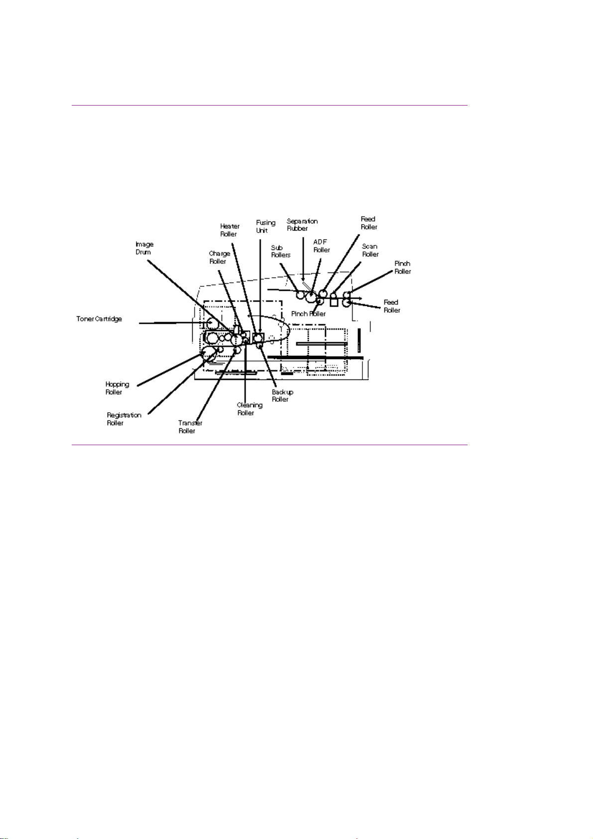
1.1.08 Major Assemblies (Mechanical) - Cross-Section Diagram
1.1.08 Major Assemblies (Mechanical)
The following major mechanical assemblies make up the facsimile machine.
· Automatic Document Feeder (ADF) Unit / Scan Unit
· Printer Unit
Page 19
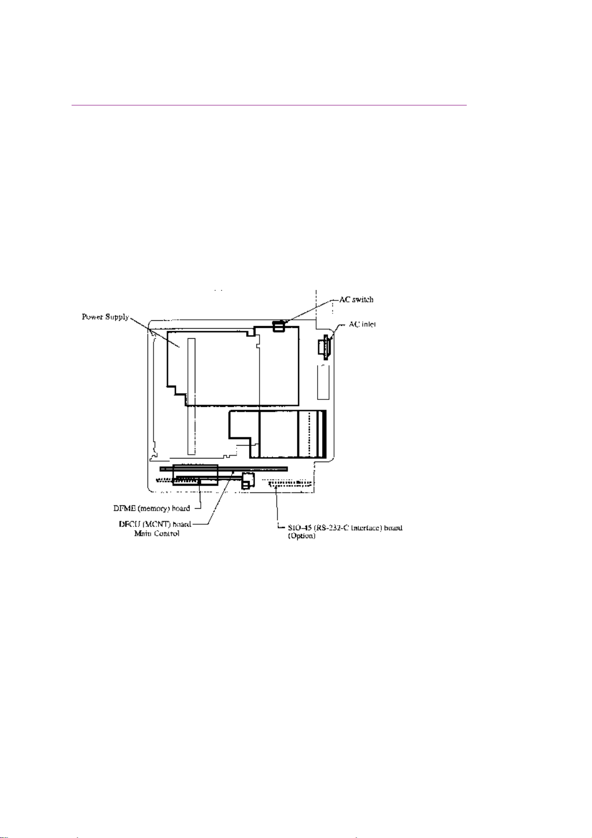
1.1.09 Major Assemblies (Electrical)
1.1.09 Major Assemblies (Electrical)
The following major electrical assemblies make up the facsimile machine.
· Main Control Board (DFCU / MCNT)
· Printer Control Board (DFPU / PCNT)
· Network Control Board (NCU)
· Operator Panel Assembly Not Shown
· Power Supply Unit Not Shown
· Memory Board Not Shown
· Line Interface Board Not Shown
· Hook Switch Board Not Shown
· Connecting Board
· Second Paper Tray Mechanism Board
Page 20

Page 21
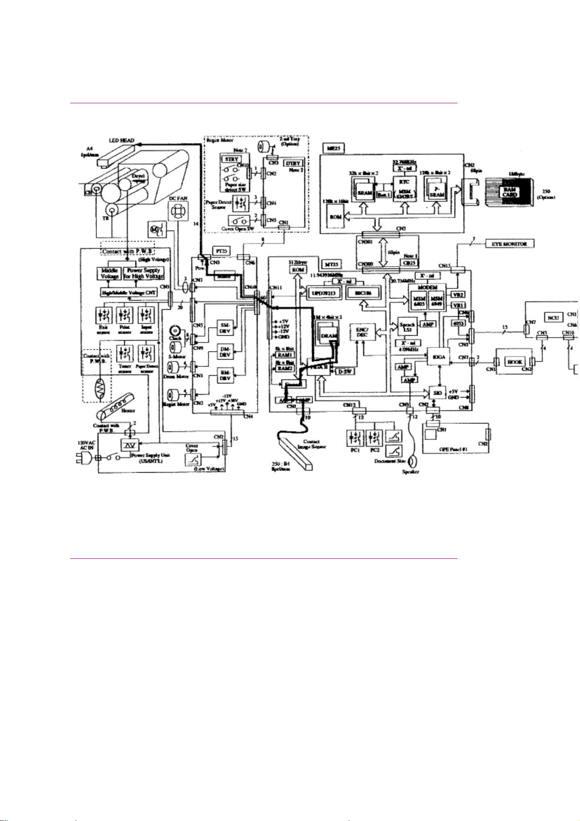
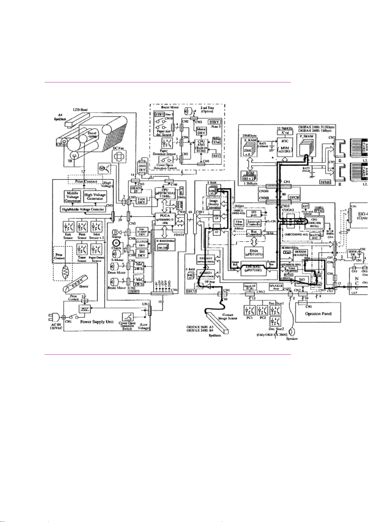
Okifax 2200 - Copy Function Block Diagram
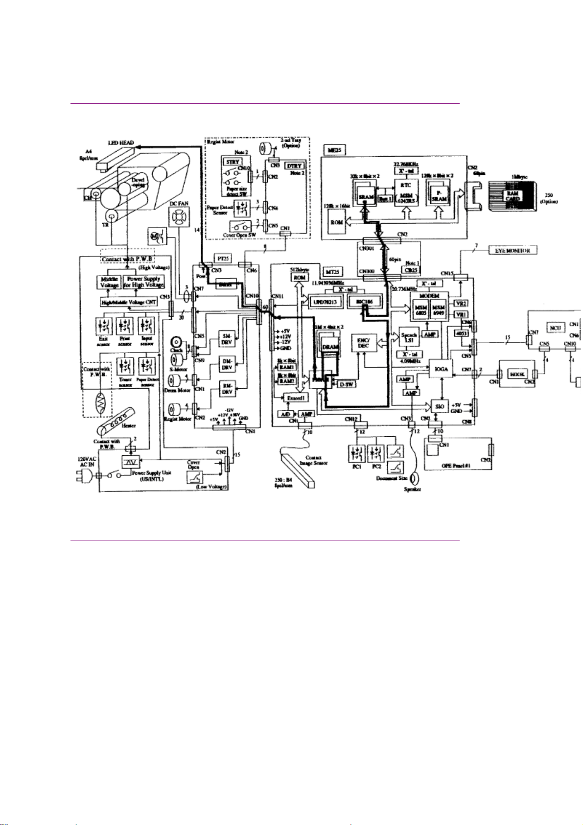
Okifax 2200 - Copy Function Block Diagram
Page 22
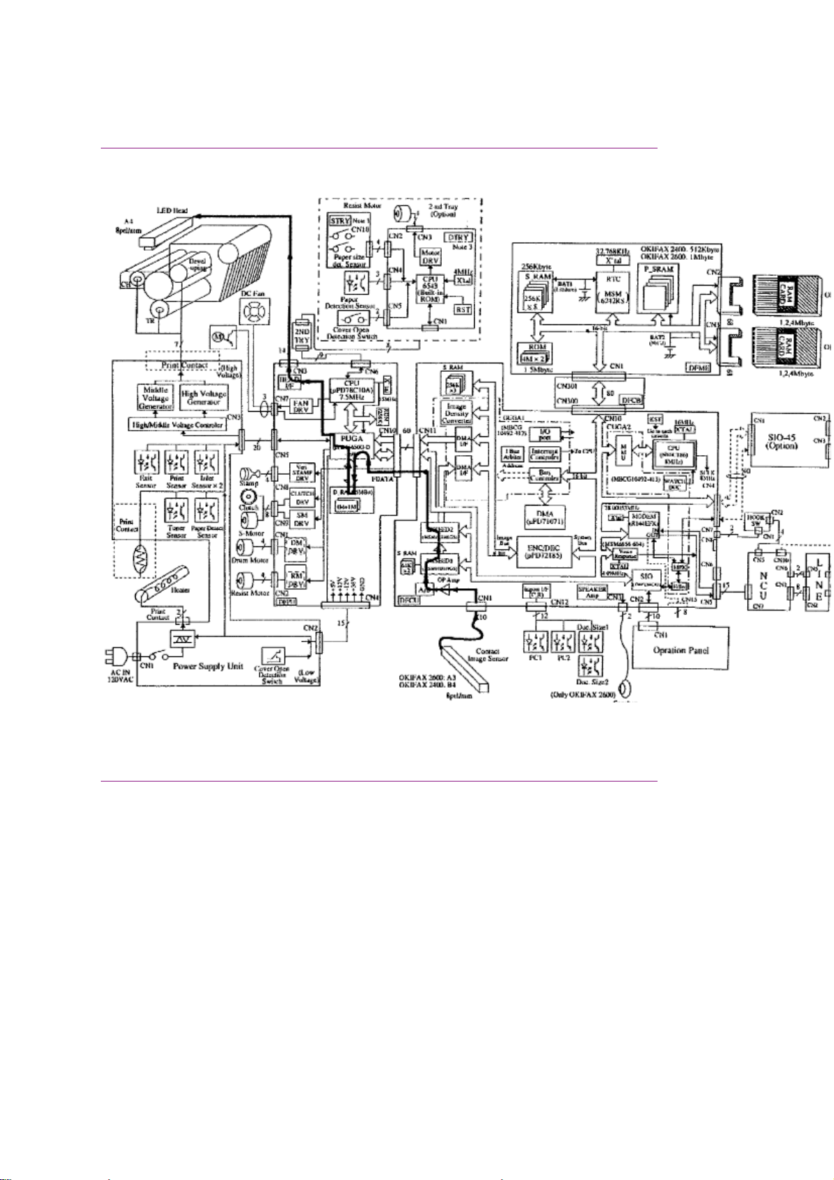
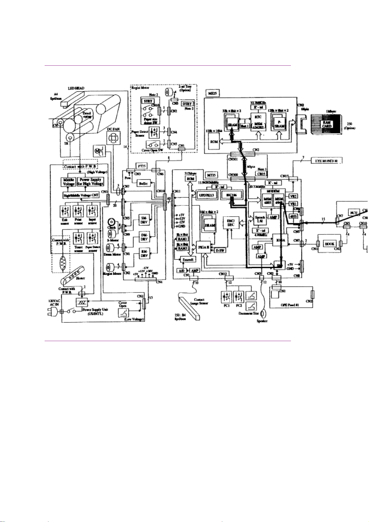
Okifax 2400/2600 - Copy Function Block Diagram
Okifax 2400/2600 - Copy Function Block Diagram
Page 23
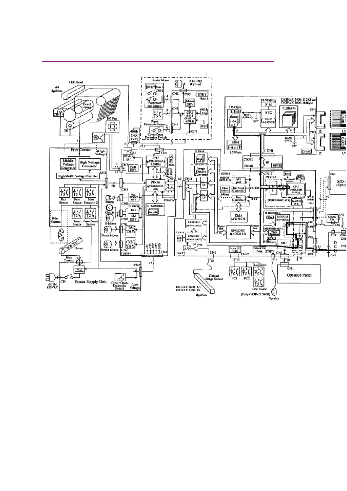
Okifax 2200 - Report Print Function Block Diagram
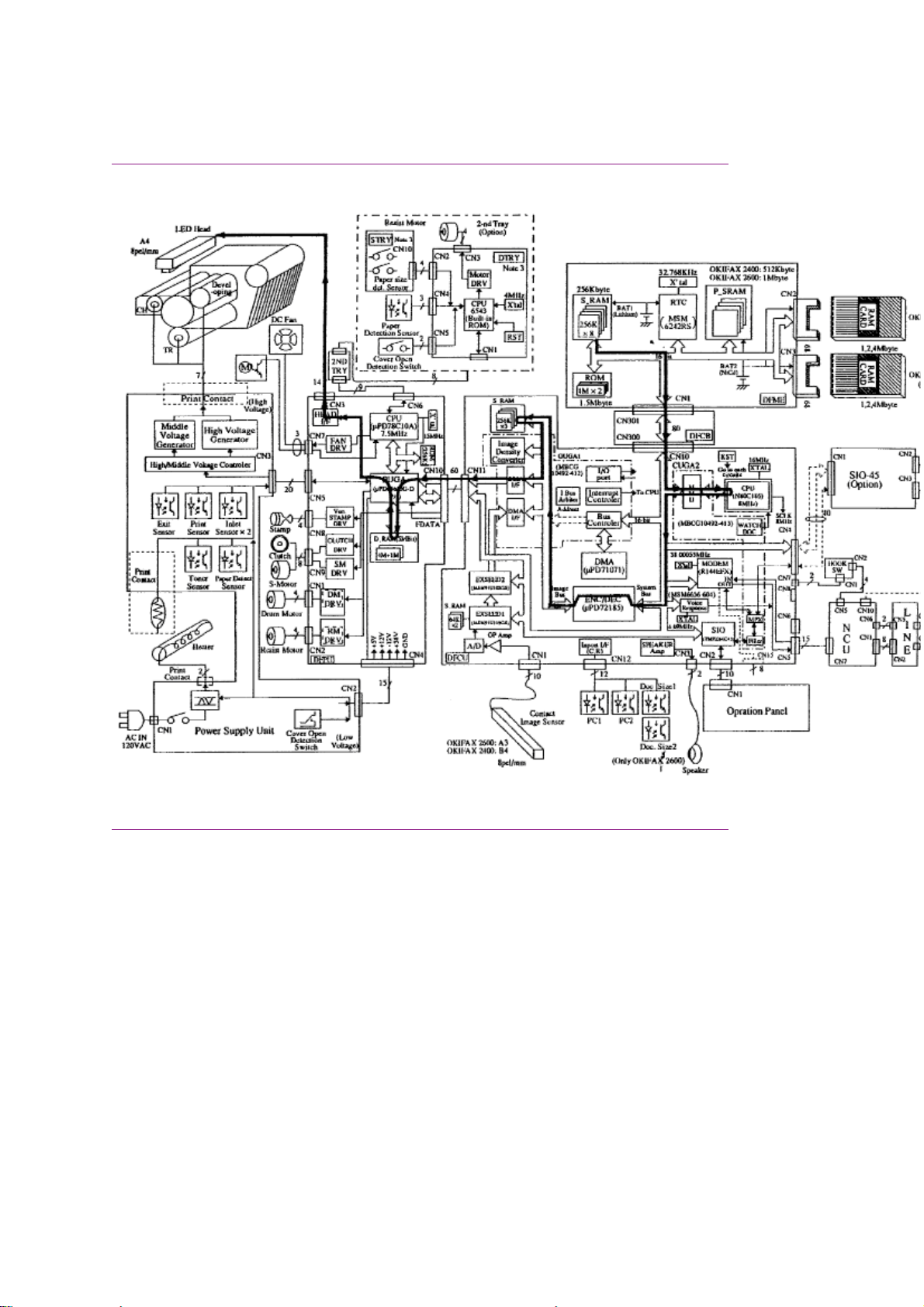
Okifax 2200 - Report Print Function Block Diagram
Page 24
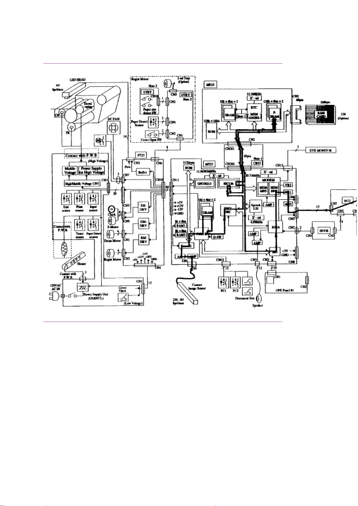
Okifax 2400/2600 - Report Print Function Block Diagram
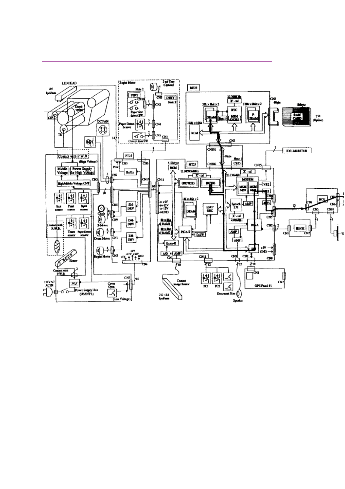
Okifax 2400/2600 - Report Print Function Block Diagram
Page 25

1.2 Transmitter Theory Of Operation
1.2 TRANSMITTER THEORY OF OPERATION
1.2.01 Typical Transmission
When a telephone number is dialed through the machine (either manually or through auto-dial), a
connection will be established with the receiving station through the Public Switched Telephone Network
(PSTN). When the call is answered, the operator will hear the Called Equipment Device (CED) tone from
the receiving station. With CED received, the transmit machine acknowledges that the connection is
established and proceeds to the CCITT T.30 300 bps handshake procedure.
NOTE:
Refer to the Receive and Transmit Handshake Procedure Block Diagrams for functional overviews of 300
bps handshaking.
Refer to the Transmit Block Diagram for an overview of G3 Transmit Operations
When the Digital Identification Signal (DIS) is received, G3 mode transmission is possible and the
document is scanned, page by page. The image data is temporarily stored in First In First Out (FIFO)
memory until it becomes valid for transmission. In approximately three seconds, the machine will receive
Called Subscriber Identification (CSI) from the distant station. After reading the document pages and
storing the image data in memory, the machine begins the handshake with the distant station. If the
14.4/9.6 kbps training is successfully completed, the machine will start transmitting the image data in
digital, coded form. Training is a high speed data pattern transmitted to the receive modem. This training
data pattern causes the receive modem to synchronize with the transmit modem. If the training fails due to
bad phone line conditions, an automatic fallback to a lower rate will occur. The result will be indicated on
the LCD display. As the machine transmits each page of image data, the page count on the LCD display
will increment.
Training performs the functions listed below.
· Training tests the line condition for valid transmissions at a particular data rate. The TCF consists of
100 binary zeroes transmitted in a burst. At least 98% accuracy must be achieved before
transmission can take place at that data rate.
· The receiving station uses training to set the preliminary equalization for the current line conditions.
Page 26
Okifax 2200 - 300 Bps Transmit Handshake Operation Diagram
Okifax 2200 - 300 bps Transmit Handshake Operation Diagram
Page 27
Okifax 2400/2600 - 300 Bps Transmit Handshake Operation
Diagram
Okifax 2400/2600 - 300 bps Transmit Handshake Operation Diagram
Page 28
Okifax 2200 - 300 Bps Receive Handshake Operation Diagram
Okifax 2200 - 300 bps Receive Handshake Operation Diagram
Page 29
Okifax 2400/2600 - 300 Bps Receive Handshake Operation Diagram
Okifax 2400/2600 - 300 bps Receive Handshake Operation Diagram
Page 30
Okifax 2200 - G3 Transmit Functional Block Diagram
Okifax 2200 - G3 Transmit Functional Block Diagram
Page 31

Okifax 2400/2600 - G3 Transmit Functional Block Diagram
Okifax 2400/2600 - G3 Transmit Functional Block Diagram
Page 32

1.2.02 Operator Panel Assembly (OPE)
1.2.02 Operator Panel Assembly (OPE)
Through the operator panel assembly, the end user initiates transmit and receive operations, sets desired
options, programs telephone numbers and other data, and interfaces in all areas of the operation of the
machine. The panel consists of an LCD display (two rows of 20 characters), a numeric key pad, nine LED
indicators, and function keys. The functions of the keys and indicators are described in the Users
Documentation.
Page 33

1.2.03 Automatic Document Feeder (ADF)
1.2.03 Automatic Document Feeder (ADF)
The automatic document feeder transfers document sheets to the scan unit automatically, one at a time.
The following diagram shows the mechanism used for detecting the leading and trailing edges of a
document.
When a document is placed on the feeder, it is sensed by the document detect sensor (PC1). This causes
the feed rollers to activate, feeding the document. The document is fed to the PC2 lever, where the
leading edge of the document is detected. When transmit (or copy) begins, the document is fed by the
transmit stepper motor to the start scan position. The documents trailing edge is detected when the PC2
lever is released. If another document is on the feeder, the process is repeated.
The Okifax 2200/2400/2600 also contain a B4 paper width sensor (PC1). The Okifax 2600 has an
additional photosensor (PC1) to detect A3 paper width.
The separation rubber holds back the top originals and allows only one document to be fed into the
scanner area. The separation rubber and automatic document feed rollers should be cleaned or replaced
according to the cleaning schedule (in Module 3 of this manual) to assure proper operation.
The automatic document feed capacity is 50 pages of 20 pound paper. Place documents (on the feeder)
image side DOWN. When feeding multiple pages, the bottom page is fed first, working toward the top.
Page 34

*1.2.04 Scanner Assembly
1.2.04 Scanner Assembly
The Okifax 2200 and 2400 use a 2048-bit element direct contact type image scanning sensor. The Okifax
2600 uses a 2432-bit element direct contact image scanning sensor. LEDs are located at the bottom of
the scan glass and image sensors are located at the top of the glass. When the document reaches the
scanning unit, it passes directly in front of the image sensor. The LEDs illuminate the document and the
light reflects back to the image sensors. This image data is sent to the printer control board via the main
control board. The transmitted document length is limited to 14 inches; however, the machine can be
modified for longer transmissions. (See
Transmission will stop and a line disconnect will occur if the end of the document is not detected within 14
inches after scanning begins (unless the unit is set for unlimited transmission.) This message will be
displayed if the document does not reach the scanning position within five seconds after the start of a
document feed.
Okifax 2200 RELOAD DOCUMENT
CONFIRM AND "STOP"
Okifax 2400/2600 (DATE/TIME, RX MODE)
REMOVE DOCUMENT AND "STOP"
Transmitting Long Documents in the Users Documentation)()
NOTE:
When a jam condition is displayed on the operator panel during message transmission, the machine will
stop, but its receiving capability will remain active.
Page 35

1.2.05 Encoder
1.2.05 Encoder
Scanned image data received by the board is sent to the encoder/decoder (ENC/DEC) integrated chip of
the main control board. The image data is compressed by the ENC/DEC according to the Modified
Huffman (MH) and Modified Read (MR) encoding scheme, or MH only. The use of MH only or both MH
and MR is determined by a function setting. Data is then stored in the FIFO area in one byte units. Fill bits
are inserted if the length of one encoded line is less than the minimum scan time of the remote unit. Data
is transferred to the network control unit, then sent to the line interface board for transmission over the
phone line.
Page 36

1.2.06 Modem
1.2.06 Modem
The modem, located on the main control board, modulates the data in the correct G3 (14.4, 12, 9.6, 7.2,
4.8, or 2.4K bps) data rate that was determined during handshaking between the local machine and the
remote receiver. Modulation is the process of converting the digital output of the scanner into an analog
signal that can be transmitted over the telephone system.
Page 37

1.2.07 Network Control Unit (Ncu)
1.2.07 Network Control Unit (NCU)
The network control unit receives the modulated data from the main control board and transfers the data
to the line interface board.
The network control unit performs the following functions during the transmit operation.
· Unit connection / disconnection to the telephone line via the CML Relay
· Dial pulse generation
· PIS tone detection
· OFF-HOOK detection (Line Current Detector)
· TX output signal attenuation (normally 9 decibel output)
· Separation of the TX and RX signals (performed by the Hybrid Transformer)
· Impedance matching (the 600 ohm impedance of the telephone line)
Page 38

1.2.08 Line Interface Board
1.2.08 Line Interface Board
The line interface board provides the RJ-11 connection used to transmit data to the PSTN, PBX, or
Leased Line.
Page 39

1.3 Receiver Theory Of Operation
1.3 RECEIVER THEORY OF OPERATION
1.3.01 Operator Panel
Through the operator panel, the user initiates manual receive operations and sets auto-answer options.
1.3.02 Line Interface Board
The line interface board provides the RJ-11 connection used to receive data from the PSTN, PBX, or
Leased Line.
1.3.03 Network Control Board (NCU)
The network control unit receives the modulated data from the line interface board and sends it to the
modem (located on the main control board). The operation of the network control unit in the receive mode
is very similar to the transmit mode. However, during receive operations, the network control unit also
functions as an amplifier for the received signal.
1.3.04 Modem
The modem demodulates the data from the G3 (14.4, 12, 9.6, 7.2, 4.8, or 2.4K bps) scheme that was
determined during handshaking. The data is then sent to the RAM memory for temporary storage. The
storage time is dependent on whether the machine is printing real-time or from memory.
1.3.05 Decoder
The decoder decodes the MH, MR, or MMR data from the RAM into lines of picture data that are 1,728
bits in length. After the data has been received, demodulated, and decoded, it is transferred to the printer
control board.
1.3.06 Document Size
Since the available printing area of the printer is smaller than the paper size, document contents may be
missed on both sides of the paper, or a document image having the same length as the printing paper
may be split into separate pages during printing. To prevent this, the unit automatically sets the proper
reduction ratio within the range of 76 to 100% if the RX REDUCTION function has been set ON. If a
received document image is longer than the available printing length, the excess part of the image is
eliminated. If the SPLIT PRINT function has been set ON, the excess image will be printed on the next
page.
Page 40

Okifax 2200 - G3 Receive Operation Block Diagram
Okifax 2200 - G3 Receive Operation Block Diagram
Page 41

Okifax 2400/2600 - G3 Receive Operation Block Diagram
Okifax 2400/2600 - G3 Receive Operation Block Diagram
Page 42

1.4 Led Printer - Principal Components
1.4 LED PRINTER
1.4.01 Principal Components
The principal hardware components of the printer unit are listed below.
· Printer Control Board
· Power Supply Unit
· Fuser Unit
· Main Motor
· LED Head
· Registration Motor
· DC Fan
· Second Paper Tray Mechanism (option)
1.4.02 Printer Control Board
The printer control board contains a printer unit gate array, 7.5 megahertz microprocessor, send motor
driver (transistor array), registration motor driver integrated circuit, drum motor driver integrated circuit,
and fan motor driver transistors.
This board controls the paper feed and paper transport functions. It also activates the LED array diodes,
which leave a latent electrostatic image on the photosensitive drum. This latent image is printed by fusing
toner to the paper.
1.4.03 Power Supply Unit
The power supply is a switching-type unit, which generates the following voltages from the AC input
voltage.
· + 5 vdc : Printer Logic
· + / - 12 vdc: Interface Signal Levels
· + 38 vdc: Transmit Stepper Motor, Registration / Drum Motor Drive,
Fan Drive, High-Voltage Source.
When the board enables the HEATON signal, the power supply provides the AC voltage to the fuser lamp.
1.4.04 Power Supply Board Components and Functions
The power supply consists of integrated circuit 1 (a one-chip CPU), a cover-open switch, the high,
medium, and low voltage generation circuits and photosensors.
Photosensors
· Outlet Sensor (PS1) ON: Paper is present
Detects paper jams at the paper exit path.
· Paper Sensor (PS2) ON: Paper is present
Along with the outlet sensor, is used to monitor paper feed and paper length.
· Inlet Sensor 1 (PS3) ON: Paper is present
Detects the leading edge of the paper.
Used to determine when to switch from the hopping to the feeding operation.
· Paper End Sensor (PS4) ON: Paper is present
Detects the presence of paper in the cassette.
· Inlet Sensor 2 (PS5) ON: A4 or larger
Detects the width of the receive paper.
· Toner Low Sensor (PS6)
Detects a low toner condition
Cover Open Switch
Whenever the stacker cover is opened, the cover open switch is turned OFF. This removes the + 38 vdc
Page 43

source voltage from the high-voltage generation circuit. As a result, all high-voltage outputs are disabled.
The CVOPN signal is sent to the main control board and the cover open routine is performed. The
message COVER OPEN will be displayed on the operator panel.
High-Voltage Circuits
The following voltages are generated for use in the electrostatic printing process.
OUTPUT
SB1/SB2 - 450 vdc Toner Supply Roller
DB1/DB2 +/- 300 vdc Toner Development Roller
TR1/TR2 + 1 Kvdc/-750 vdc Transfer Roller
CH - 1.3 Kvdc Charging Roller
CB + 400 vdc Toner Cleaning Roller
1.4.05 Fuser Unit
The fuser unit is controlled by a thermistor, the printer interface gate array (PIGA), an LSI, and the CPU to
keep the heat roller surface temperature within a predetermined range (about 150 degrees Celsius). A
thermal fuse within the fuser unit prevents abnormal temperature rises in case the thermistor fails.
NOTE:
The CPU checks for an open circuit in the thermistor at power-on. A fuser alarm is set if this error is
detected.
The CPU also sets a fuser alarm if the proper temperature is not attained within a specified period of time
after power-on.
VOLTAGE USE
Upon detecting a fuser alarm, the CPU will stop printing (after printing the current page).
1.4.06 Main Motor (Drum Motor)
The main motor is controlled by the motor control LSI, on the main control board via the printer control
board. The motor used is a four-phase motor, driven by the motor driver integrated circuit located on the
printer control board.
1.4.07 LED Array
The printer control board provides serial transfer of print data (HDDT0) to the LED array. The signal
HDCLK provides data transfer timing. 1728 bits of data are shifted into the LED array registers. Then, the
signal HDLD loads this data into the latch circuits. This enables the individual LEDs.
1.4.08 DC Fan
The fan is controlled by the FAN ON-P signal from the main control board via the printer control board. In
order for the facsimiles printer to operate, the signal FAN SENSE-N must be active.
NOTE:
The fuser and the fan are not enabled when the cover is open. If the fan fails to run, the fuser will turn off
and the message PRINTER ALARM 3 will be displayed. Printing is disabled.
1.4.09 Registration Motor
The registration motor is driven clockwise for initial receive paper loading. It is driven counter-clockwise for
paper feeding. The motor is controlled by the motor control LSI on the main control board and is driven by
the motor driver integrated circuit on the printer control board.
Page 44

1.5 Printing Process - General Information
1.5 PRINTING PROCESS - General Information
1.5.01 General Information
Hopping and feeding are controlled by a single registration motor.
Turning the registration motor in the "A" direction drives the hopping roller.
Turning the registration motor in the "B" direction drives the registration roller.
The registration gear and hopping gear contain one-way bearings. Turning each of these gears in the
reverse direction will
turn the corresponding roller.
NOT
Printing Process Diagram
Page 45

### Printing Process Overview ####
Page 46

1.5.02 The Full Printing Process
1.5.02 Hopping
Hopping loads paper from the paper cassette.
During the hopping operation, the registration motor turns in a clockwise direction. This motor drives the
hopping roller, which in turn advances the paper until the inlet sensor 1 switches ON. The registration gear
turns, but the one-way bearing does not allow the registration roller to turn.
After inlet sensor 1 switches ON, the paper is advanced a predetermined length (until the paper reaches
the registration roller).
1.5.03 Feeding
Feeding transports paper through the printer.
After the completion of hopping, the registration motor turns in a counter-clockwise direction. This
counter-clockwise motion drives the registration roller and advances the paper. The hopping gear turns,
but the one-way bearing does not allow the hopping roller to turn.
1.5.04 Charging
Charging applies -1.3 Kvdc to the charge roller. The charge roller contacts the image drum surface.
The charge roller has two layers: a conductive layer and a surface protective layer. The surface layer is
flexible, which assures proper contact with the photosensitive drum.
Page 47

1.5.05 Exposing
The image drum has four layers.
· Carrier Transfer Layer (CTL)
· Carrier Generation Layer (CGL)
· Underlayer (UL)
· Aluminum Base
The CTL and CGL make up the organic photo conductor layer (OPC), which is about 20 micrometers (m
m) thick.
When light from the LED head irradiates the image drum surface, the light energy generates positive and
negative carriers in the CGL. The positive carriers are moved to the CTL by an electrical field acting on the
image drum. The negative carriers flow into the aluminum layer (ground).
The positive carriers moved to the CTL combine with the negative charges on the image surface
(accumulated by the contact charge of the charge roller), lowering the potential on the image drum
surface. The resultant drop in the potential of the irradiated part of the image drum surface forms an
electrostatic latent image on it. The surface potential on this irradiated part of the image drum is
approximately -100 vdc.
Page 48

1.5.06 Developing
The electrostatic latent image formed on the image drum surface is developed into a visible image.
Developing takes place when contact is made between the image drum and the developing roller.
As the toner supply roller rotates, toner is absorbed into the sponge type roller material.
A charged particle will be attracted to a particle having a MORE POSITIVE charge than its own.
The developing roller surface is charged to -300 vdc and the toner supply roller is charged to -450 vdc.
Since the development roller is charged more positive than the toner supply roller, the toner on the toner
supply roller is attracted to the developing roller. The toner on the developing roller contacts the doctor
blade, forming a thin coat of toner on the developing roller surface.
1.5.07 Transfer
The transfer roller is made of a conductive sponge material. The roller keeps the paper in constant contact
with the image drum. Paper is placed over the image drum surface. A positive charge (opposite in polarity
to the toner) is applied to the paper from the reverse side.
A charged particle will be attracted to a particle having a MORE POSITIVE charge than its own.
A high positive charge is applied to the transfer roller by the power supply board. This induced charge (on
the surface of the transfer roller) is transferred to the paper when contact is made between the transfer
roller and the paper. The lower side of the paper is positively charged. The negatively charged toner (on
the photosensitive drum) is transferred to the upper side of the paper because of the positive charge on
the lower side of the paper.
Page 49

The exposed portion of the image drum contains a more positive charge than the development roller (-100
vdc vs -300 vdc). Therefore, toner is attracted to the exposed areas of the image drum, making the
electrostatic latent image visible.
NOTE:
The toner supply roller and the developing roller are supplied with the bias voltages required during the
developing process. The toner supply roller is charged to -450 vdc. The developing roller is charged to
-300 vdc.
1.5.10 Printing
Refer to the Printing Process Diagram.
Printing is accomplished as follows.
· Approximately - 1.3 Kvdc is supplied to the charge roller. This causes the drum to charge to
approximately - 750 vdc.
· The LED head is turned ON by the printer control board in accordance with signals from the main control
board. This causes a latent electrostatic image to be formed on the surface of the drum.
· Through the development process, a toner image replaces the electrostatic image.
· A + 1 Kvdc charge is applied to the transfer roller. This causes the toner image to be transferred to the
receive paper.
· Heat and pressure cause the toner image to become fused to the receive paper. The 150 degree
Page 50

Centigrade fusing temperature is attained by turning a 400 watt halogen lamp ON. The fusing temperature
is controlled by a thermistor. In the event of a thermistor failure, a temperature fuse will OPEN, turning off
the quartz lamp, and preventing equipment damage.
· The residual toner is removed from the drum.
Printing Process Diagram
Page 51

1.6 Sensors And Switches
1.6 SENSORS AND SWITCHES
1.6.01 Paper Jam Detection
Paper jam detection monitors the location of paper when the printer is powered ON and during printing. If
any of the following jams are present, the printing process is interrupted and the message PAPER JAM
will be displayed on the LCD.
To return to the printing process, the paper jam condition MUST be cleared. This is accomplished by
opening the upper cover, clearing the jam, and closing the cover.
Paper Outlet Jam
NOT
This jam occurs if the paper does
However, the paper has already passed over the paper sensor.
Paper Size Error
The time interval between when the paper contacts the paper sensor and the outlet sensor determines
which size (length) paper is being used.
This error occurs if the paper size of the loaded paper differs by + 45 mm or more from the paper size set
by the menu.
Cover Open Switch
When the stacker cover is opened, the cover open microswitch on the power supply unit is deactivated.
This disables the + 38 vdc and the high voltage power supply circuit. As a result, all high voltage outputs
are interrupted. At the same time, the CVOPN signal is sent to the main control board main control board
to notify it of the OFF state of the microswitch. The main control board executes the cover open routine.
The operation panel displays the message COVER OPEN.
pass over the outlet sensor within a pre-determined period of time.
Page 52

Page 53

Paper Inlet Jam
Paper Inlet Jam
This jam occurs when either of the following situations occur.
· When the printer is powered ON, paper is at inlet sensor 1.
· After the hopping operation is attempted three times, the leading edge of the paper does
reach inlet sensor 1.
NOT
Page 54

Paper Feed Jam
Paper Feed Jam
This jam occurs when either of the following conditions occur.
· The paper does not pass over the paper sensor within a pre-determined period of time.
· The leading part of the paper does not reach the outlet sensor within a pre-determined period of
time after the paper has passed over the paper sensor.
Paper Feed Jam Timing Diagram
Page 55

1.6.02 Toner Low Sensor
1.6.02 Toner Low Sensor
The toner well of the image drum cartridge contains a toner agitator. Whenever the image drum
rotates, the toner agitator attempts to turn. A spring clip in the bottom of the toner well (along with the
proper amount of toner) holds the agitator at the bottom of the well. However, when toner is distributed
unevenly or an insufficient amount of toner is in the well, the toner agitator will rotate. Therefore, as
long as the toner well contains an adequate supply of evenly distributed toner, the toner agitator will
not rotate.
The toner sensor lever has a magnet embedded in it. Whenever the toner agitator is positioned at the
bottom of the toner well, the toner sensor lever is magnetically attracted to the toner agitator. This causes
the toner sensor lever to be lifted from the path of the toner sensor.
During a low toner condition (less than 20 grams of toner remaining), the toner agitator will rotate
continuously
panel will then display the TONER LOW message.
. This causes the toner sensor to turn ON / OFF as the image drum rotates. The operator
During an unevenly distributed toner condition, the toner agitator will rotate
sufficiently
operator panel will not display an error message since this is normal printer operation.
. This causes the toner sensor to turn ON / OFF for only a few image drum rotations. The
until the toner is distributed
Page 56

Chapter 2
*2.1 Overview
2.1 OVERVIEW
2.1.01 Introduction
This section is used to isolate problems to the assembly level. Application problems and detection of faulty
components on the printed circuit boards are not addressed.
When troubleshooting a defective unit, refer first to Module 2.4 of this Service Handbook(). This section
contains tips on preventing problems as well as a list of common problems.
Next, refer to Module 2.5. Repair Analysis Procedures (RAPs()) will ask you questions or require you to
make observations. The answers to these questions and the results of your observations determine your
next course of action. Use the RAP Index to identify which RAP should be used to resolve the problem
with the machine.
If you encounter a situation that is not addressed by the documentation in this kit, please report the
problem to Okidata. Send your report to the Okidata Technical Training Group. Refer to the Service
Center Reference Guide for information on contacting Okidata.
The following information is provided to detect and analyze failures.
1. Okilink II, Faxable Facts, Technical Service Bulletins
2. Troubleshooting Tips / Common Problems
3. Repair Analysis Procedures
4. Tests
5. Reports
6. Resets
7. Technical Functions
8. TEL / FAX Automatic Switching
9. Touch Tone Mode
10. User Functions
11. Dialing Parameters
Page 57

2.2 Troubleshooting Updates
2.2 TROUBLESHOOTING UPDATES
2.2.01 General Information
Okidata distributes updated troubleshooting information in three ways.
1. Okilink II
2. Faxable Facts
3. Technical Service Bulletins
2.2.02 Okilink II
Okilink II is Okidatas Bulletin Board Service. This service is available to all Okidata Certified Service
Technicians. Okilink II provides additional troubleshooting and service information. Technicians can
download files, ask questions of Okidatas technical support personnel, and participate in round table
discussions about Okidata products and services. Technical Service Bulletins, Recommended Spare
Parts Lists, Printer Drivers, Product Specifications, and Service Training Information are also available.
Refer to the Service Center Reference Guide for information on accessing Okilink II.
2.2.03 Faxable Facts
Okidatas Faxable Facts is an automated fax document retrieval system. It is maintained by Okidatas
Customer Information Center. Answers to common questions about Okidata products are available
through faxable facts.
Refer to the Service Center Reference Guide for information on accessing Faxable Facts.
2.2.04 Technical Service Bulletins
Okidatas Technical Service Bulletins (TSBs) contain technical information obtained after product release.
Firmware updates, part number changes, and procedural changes are some of the subjects covered by
these bulletins. The TSBs are distributed through Okilink II.
Refer to the Service Center Reference Guide for information on accessing Okilink II.
Page 58

2.3 Reporting Problems
2.3 REPORTING PROBLEMS
2.3.01 General Information
Okidata strives to provide accurate and detailed service information through its training materials. The
Technical Training Group realizes that service technicians have valuable experience, knowledge, and
opinions. Okidata strongly encourages you to report any problems you may encounter when using the
materials of this training kit. Please be as specific and detailed as possible. Your comments, suggestions,
and criticisms are used to update and revise training kits.
You should reference the training materials when servicing Okidata products. Most problems can be
solved by using the information provided in the training materials. If you encounter a situation that cannot
be solved, please let Okidata know.
Refer to the Service Center Reference Guide for information on contacting Okidata.
2.3.02 Problem Lists
Technicians frequently request a list of common problems specific to a product. Technical Training Kits
are written before a product is shipped to customers. Therefore, such information is not available when a
product is first released.
However, Okidata wants to respond to these requests. Okilink II provides round-table discussions on
technical problems. Errors and corrections in the training materials are listed in the Training Section of
Okilink II. The Technical Service Bulletins (also known as Okidatas Monthly Mail) are available via Okilink
II. Situations that are not addressed in the reference documentation, Technical Service Bulletins, or round
tables may be reported to the Dealer Service and Support Engineers (DSSEs) or the Technical Training
Group. You will receive a response to your message within one business day.
The information on Okilink II is the most accurate and up-to-date technical information available from
Okidata. This is only possible with your assistance. By reporting your suggestions, concerns, and
problems, Okidata can provide the best possible information.
Your cooperation is greatly appreciated. Thank you for your help!
2.3.03 Reporting Methods
Okilink II
You may use Okilink II to report your findings. Refer to the Service Center Reference Guide for
information on using Okilink II.
Course Critique
Use the Course Critique to report any problems you find as you are completing the self-paced training.
Fax Number
If you wish to fax your response, please use the numbers listed in the Service Center Reference Guide.
Mailing Address
If you respond by mail, please use the appropriate address listed in the Service Center Reference Guide.
Information Provided
Please provide the following information when reporting problems.
1. Okidata Dealer Number
2. Technicians Name
3. Company Name
4. Companys Address (Street, City, State/Province, ZIP / Postal Code, Country)
5. Telephone and Fax Numbers (with area / country access codes)
Page 59

6. Product Name
7. Units Serial Number
8. Description of Problem
9. Document Name (with page number or procedure) with error or problem.
Page 60

2.4 Troubleshooting Tips
2.4 TROUBLESHOOTING TIPS
2.4.01 Preliminary Checks
1. Is the unit operated under the proper ambient conditions?
2. Is the paper being used made specifically for xerographic printing?
3. Have the toner cartridge and image drum been replaced as recommended?
4. Has the image drum cartridge been installed properly?
5. Is Okidata toner being used?
2.4.02 Tips for Preventing Image Problems
1. Do not let anything touch the surface of the image drum.
2.
NEVER
3. Do not touch the fusing unit. Oil from your skin can cause fusing temperature variation.
4. Do not expose the image drum to light for more than five minutes.
5. Do not touch the transfer roller. Touching the transfer roller may cause incomplete toner transfer,
resulting in faded output.
2.4.03 Common Problems
1. The display is blank.
expose the image drum to direct sunlight.
- Check that the power switch is ON.
- Check that the power cord is firmly plugged into the unit and the wall
outlet, and make sure that power is supplied to the wall outlet.
- Make sure the memory board is properly connected.
2. Nothing happens when you press the operator panel keys.
- Power OFF the unit, wait 10 seconds, then power ON the unit.
- Check that the power cord is firmly plugged into the unit and the wall outlet.
- Verify that the ROMs on the memory board are installed properly.
3. The display tells you to replace paper even though there is paper in the cassette.
- Remove the paper cassette and make sure that the paper is firmly stacked
in the cassette. Push the paper under the tabs on the sides of the paper cassette.
4. Your original document jams.
- Make sure the document is not wider than the width of the document feeder.
- Check the document for wrinkles, tears, or other damage.
- Make sure there are no staples or paper clips attached to the paper,
and that the paper is clean and dry.
- Check for contaminants on the contact image sensor.
- Make sure the feed rollers and separator pad are clean and free of contaminants.
- If the problem persists, copy the document on a photocopier and fax the copy.
5. Your unit will not dial.
- Make sure the telephone line is connected to the line jack at the rear of the unit.
- Lift the handset and check for a dial tone. If you do not hear one,
there may be a problem with your telephone line.
- If you hear a dial tone, you may be using the wrong dial method
(pulse or tone) for your area.
- Make sure the telephone jack is an RJ-11C.
6. The display shows a communication error.
- You may be trying to communicate with a non-group 3 facsimile machine.
- The remote machine may not be able to perform the function that you
want (such as polling or confidential reception).
Page 61

- The remote machine may be out of paper or experiencing a paper jam.
- Bad telephone lines can cause communication errors. Try sending the fax again.
- The receiving facsimile machine may have a service problem. Send a
fax to a different location to test your unit.
7. You sent a fax, but it was received completely blank.
- Make sure that you have loaded your document face-down.
8. You keep getting reports that you do not want.
- Check the User Function settings and disable all unwanted reports.
9. When you receive long faxes or make copies of long documents, the bottom is always cut off.
- Try enabling the RX SPLIT PRINT or COPY SPLIT PRINT User
Functions. These functions will split long documents across two pages.
10. You sent a fax, but the image the remote fax received was very poor quality.
- If your document has small type, complex illustrations, photographs or was
extremely light or dark, try changing the TRANSMIT RESOLUTION and
TYPE OF ORIGINAL settings.
- Copy the document on the unit to see how well it copies. If the copy looks
good, the problem may be telephone line interference or a defective
facsimile machine at the receiving side.
11. Your unit does not receive faxes.
- Check which reception mode is set on your unit. The mode will be displayed
in the upper right-hand corner of the LCD when the unit is in idle mode.
12. The image received on your unit is very poor.
- If your document has small type, complex illustrations, photographs or was
extremely light or dark, ask the person sending the fax to change the
TRANSMIT RESOLUTION and TYPE OF ORIGINAL Settings.
- Copy a similar document to test your unit. If the copy looks good, the problem
may be telephone line interference or a defective facsimile machine at the
transmitting side.
13. You tried dialing with a one touch key or an auto dial code but nothing happened.
- Check that the One Touch or Auto Dial key being used has a programmed number.
- Check the telephone number to make sure it was entered correctly.
- When you are dialing with an Auto Dial Code, be sure to press the Auto Dial Key
before you enter the code.
- If your unit has the AUTO START feature disabled, you must press START
to begin dialing (refer to Dialing Parameters in the Users Documentation for
AUTO START information).
- Confirm that the correct dial method is set (pulse or tone).
14. You set your unit for delayed transmission but nothing happened.
- Verify that the DATE and TIME are correctly set.
15. Your received documents are light or have vertical white streaks on them and you are not out of toner.
- You may need to replace the image drum unit.
16. Your unit disconnected before you could answer a voice request.
- You have only 15 seconds to answer a voice request. Once you hear the warbling
tone, pick up the handset, then press the VOICE REQUEST.
17. Your unit will not poll the remote fax machine.
- Call the person at the remote fax machine and make sure they have loaded
documents and placed their machine in the Polling Transmission Mode.
Page 62

- Make sure that the remote machines polling number matches the password
that you entered.
18. Someone tried to send you a confidential fax but nothing happened.
- You must set up a confidential mailbox and enter a 4-digit password before
anyone can send you a confidential fax.
- If your message is left in the unit for more than the specified amount of days,
your fax machine will erase it.
Okifax 2200: Ten days
Okifax 2400/2600: Twenty days
19. Your received faxes sometimes look distorted.
- If the received document is wider/longer than the paper loaded in the paper
cassette, the unit will automatically reduce the width/length of the document to fit.
- This could also be caused by communication problems.
20. Your unit is connected to a PBX and cannot dial out.
- You must enter your access digit(s) before the telephone number for each
number that you dial or program into your machine.
- Use the "Pause" Character after the access digits. This allows time for the
PBX to switch to an outside line.
- You should enable the PBX Function.
Okifax 2200: Dialing Parameter Settings
Okifax 2400/2600: Technical Function 61.
21. You want to answer the phone but your unit always answers first.
- If you are using an external telephone, change the units RING RESPONSE setting.
Okifax 2200: User Function 24
Okifax 2400/2600: Technical Function 65
- If you are using the Telephone/Fax Reception Mode, and require more time
to answer the telephone before the unit switches back to fax mode, modify the
TEL/FAX TIMER PRG.
Okifax 2200: User Function 10
Okifax 2400/2600: Technical Function 64
22. The unit is too loud.
- Adjust the Monitor Volume
Okifax 2200: User Function 05
Okifax 2400/2600: Technical Function 10
- Adjust the Incoming Ring Volume. The volume switch is at the rear of the unit.
- Adjust the Buzzer Volume.
Okifax 2200: User Function 16
Okifax 2400/2600: Technical Function 11
- Change the Key Touch Response.
Okifax 2200: User Function 16 (Buzzer Volume)
Okifax 2400/2600: Technical Function 12
- Change the No Paper Call Feature. (The unit warbles when it is out of paper).
Okifax 2200: User Function 11.
Okifax 2400/2600: Not applicable. Saves to memory.
Page 63

23. The machine wont program. (Okifax 2200)
- During multiple location polling reception or multiple location memory
transmission, the program menus cannot be accessed. Try again after
the operation is completed.
24. Transmission of a fax has been stopped. The ALARM is on and the document
cannot be removed. (Okifax 2200)
- Press STOP. This deactivates the ALARM.
- Press STOP.
- Remove the document.
25. The fax machine will not allow user operation. (Okifax 2200)
- A department id has been programmed. Enter the four digit department ID, then proceed.
- If a department ID is not in use, power OFF the unit. Wait ten seconds. Power ON the unit.
26. The unit is connected to an answering machine and it doesnt work.
- Enable the Telephone Answering Device (TAD) Mode.
Okifax 2200: Technical Function 45
Okifax 2400/2600: TAD Mode is not used
Page 64

2.5 Repair Analysis Procedures
2.5 REPAIR ANALYSIS PROCEDURES
2.5.01 General Information
When using the Repair Analysis Procedures (RAPs), follow these steps.
1. Work through the Start Here Flowchart. If the problem is not resolved, proceed to the next step.
2. Use the RAP Index to find the RAP which is associated with the units problem.
3. Go to the appropriate RAP.
4. All of the RAPs will begin with a START Statement, followed by either questions or another type of
statement.
Page 65

*2.5.02 RAP Index
2.5.02 RAP Index
RAP & Description()
01 No LCD Display
02 Alarm LED is lit
03 Printing Test Failure
04 Local Copy Problem
05 Auto Dial Problem
06 Data Transmission Problem
07 Auto Reception Problem
08 Reception Problem
09 Scan Operation Test Failure
10 LED Test Failure
11 Tone Send Test Failure
12 High-Speed Modem Test Failure
13 Multi-frequency Send Test Failure
14 Voice Message Test Failure
15 No Acoustic Line Monitor
16 Document Does Not Feed
17 Multiple Document Feeds
18 Document Skews
19 Document Jams
20 Problems Shown on LCD Display
20A Cover Open
20B Printer Alarm 1
20C Printer Alarm 2
20D Printer Alarm 3
20E Printer Alarm 4
20F Paper Jam
20G No Paper
21 Image Problems
21A Poor Print Quality
21B Dark Background Density
21C Printed Output is Blank
21D Vertical Black Stripes
21E Repetitive Spaced Marks
21F Vertical White Stripes
21G Areas Missing
21H Poor Fusing
Page 66

Start Here Flowchart
Start Here Flowchart
START
Does the LCD operate?
NO Refer to RAP 01().
YES Does the ALARM LED light?
YES Refer to RAP 02.()
NO Press SELECT FUNCTION. Does the appropriate message appear on the LCD?
Okifax 2200: POLLING RX
Okifax 2400/2600: SELECT FUNCTION (OT)
NO Replace the operation panel
Has the problem been resolved?
YES End of procedure.
NO Replace the main control board.
YES Perform Self Diagnosis
Go to A
A
Perform the Print Test. Are the results satisfactory?
NO Refer to RAP 03().
YES Go to the next step listed below.
Is the ROM check OK?
NO Replace the ROM on the printer control board. Then, replace the ROM(s) on the memory
board.
YES Go to the next step listed below.
Is the RAM check OK?
NO Replace the following in the listed order
1. Memory Board
2. Main Control Board
3. Printer Control Board
YES Is the Local Copy OK?
NO Refer to RAP 04 (No Local Copy)().
YES Go to the next step listed below.
Is the Auto Dial OK?
NO Refer to RAP 05 (Auto Dial Failure).()
YES Is there a data transmission problem?
YES Refer to RAP 06 (Data Transmission Problem).()
NO Go to the next step listed below.
Is Auto Reception OK?
NO Refer to RAP 07 (Auto Reception Failure)().
YES Is there a reception problem?
YES Refer to RAP 08 (Reception Problem)().
NO Verify symptom and refer to the appropriate RAP.
Page 67

RAP 01 No LCD Display
RAP01 No LCD Display
START
Is the LCD lit?
NO Is the unit powered ON?
NO Power ON the unit. Verify that the memory board is properly installed.
YES Go to CHECK 1.
YES Press SELECT FUNCTION. Does the appropriate message appear on the LCD?
Okifax 2200: POLLING RX
Okifax 2400/2600: SELECT FUNCTION (OT)
YES End of procedure.
NO Go to CHECK 1.
CHECK 1
Is +5 vdc present at pins 7, 8, 14, 15 of CN4 on the printer control board?
NO Go to CHECK 2
YES Is +5 vdc present at pin 2 of CN1 on the operator panel board?
YES Replace the operation panel.
NO Go to CHECK 2.
CHECK 2
Make sure the main control board and the operator panel board, and their connecting cables are
properly installed. Then, replace the power supply board.
Has the problem been resolved?
YES End of procedure.
NO Replace the main control board.
Has the problem been resolved?
YES End of procedure.
NO Check that the memory board is properly connected.
If the problem remains, replace the memory board.
Page 68

*RAP 02 Alarm Led Is Lit
RAP 02 Alarm LED Is Lit
START
Is the problem a communication error?
NO Go to CHECK 1.
YES Press the STOP key.
Does the ALARM LED go OFF?
YES End of procedure.
NO Go to CHECK 1.
CHECK 1
Is "COVER OPEN" displayed on the LCD?
YES Refer to RAP 20A().
NO Is "PRINTER ALARM (1-4)" displayed on the LCD?
YES Refer to the appropriate RAP. (20B, C, D, or E)
NO Is "PAPER JAM" displayed on the LCD?
YES Refer to RAP 20F().
NO Go to the next step listed below.
Is "NO TONER" displayed on the LCD?
YES Perform each of the following until the problem is resolved.
Replace the toner cartridge.
Try a known "good" drum cartridge.
Replace the printer control board.
NO Is "DOCUMENT JAM" displayed on the LCD?
YES Refer to RAP 20F.
NO End of procedure.
Page 69

RAP 03 Print Test Failure
RAP 03 Print Test Failure
START
Perform the Self Diagnosis Test.
Is the Self Diagnosis Test OK?
YES End of procedure.
NO Perform the Print Test.
Is the Print Test OK?
NO Refer to the RAP 21.
YES Replace the printer control board.
Has the problem been resolved?
YES End of procedure.
NO Replace the main control board.
Page 70

RAP 04 Local Copy Problem
RAP 04 Local Copy Problem
START
Perform the Self Diagnosis Test. Are the results satisfactory?
NO Refer to RAP 03.
YES Load a document.
Does the document reach PC1 photocoupler?
NO Perform each of the following until the problem is resolved.
Check PC1.
Replace the main control board.
Verify that the scan motor assembly is operating properly.
YES Is the document fed about three inches and stops with
"SELECT LOCATION" displayed on the LCD?
NO Perform each of the following until the problem is resolved.
Check PC2.
Replace the main control board.
YES Go to the next step listed below.
Press the COPY key. Is the copied document all black?
YES Verify that -12 vdc is present at Pin 9 of CN2 of the power supply board.
If the voltage is not present, replace the power supply board.
NO Is the quality of the copy acceptable?
YES End of procedure.
NO Perform a Scan Adjustment.
Has the problem been resolved?
YES End of procedure.
NO Perform each of the following until the problem is resolved.
Replace the main control board.
Replace the contact image sensor assembly.
Page 71

Checking PC1 And PC2
Checking PC1 and PC2
Okifax 2200 / Okifax 2400
This unit has two PC1 sensors and one PC2 sensor.
To check the sensors, follow this procedure.
1. Place the positive lead from a digital multimeter at the points listed below.
PC1 (Document Detect Sensor): Main Control Board CN 12, Pin 2
PC1 (B4 Width Sensor): Main Control Board CN 12, Pin 8
PC2 (Paper Leading Edge Sensor): Main Control Board CN 12, Pin 5
2. Place the negative lead of the digital multimeter on frame ground.
3. While making contact with the pin , press the appropriate lever. The voltage should go from +5 vdc to 0
vdc.
4. Release the lever. The voltage should return to +5 vdc.
5. If necessary, replace the sensor.
Okifax 2600
This unit has three PC1 sensors and one PC2 sensor.
To check the sensors, follow this procedure.
1. Place the positive lead from a digital multimeter at the points listed below.
PC1 (Document Detect Sensor): Main Control Board CN 12, Pin 2
PC1 (B4 Width Sensor): Main Control Board CN 12, Pin 8
PC1 (A3 Width Sensor): Main Control Board CN 12, Pin 11
PC2 (Paper Leading Edge Sensor): Main Control Board CN 12, Pin 5
2. Place the negative lead of the digital multimeter on frame ground.
3. While making contact with the pin , press the appropriate lever. The voltage should go from +5 vdc to 0
vdc.
4. Release the lever. The voltage should return to +5 vdc.
5. If necessary, replace the sensor.
Page 72

RAP 05 Auto Dial Problem
RAP 05 Auto Dial Problem
Make sure that the selected dialing method (tone/pulse) is appropriate for the TELCO / PBX needs. Refer
to the Dialing Parameters in the Users Documentation.
START
Does the manual dial function properly?
NO Can a dial tone be heard when the handset is picked up?
NO Check the line cable and the exchange.
YES Check for closed network, method of dialing, dial rate.
YES Replace the problem unit with a known " good" unit. Does the "good" unit dial?
NO Go to LOCATION PROBLEM.
YES Does "DIALING" appear on the LCD display?
YES End of procedure.
NO Does "TELEPHONE BUSY" appear on the LCD display?
NO End of procedure.
YES Hang up the external telephone set.
Has the problem been resolved?
YES End of procedure.
NO Replace the following.
Network control board
Main control board
LOCATION PROBLEM
Check the following.
One Touch and Auto Dial parameters
OFF-Hook Bypass
Has the problem been resolved?
YES End of procedure.
NO Contact Technical Support.
Page 73

RAP 06 Data Transmission Problem
RAP 06 Data Transmission Problem
This section explains how to localize the cause of problems occurring after completion of connection with
a remote station.
START
Adjust send signal power level.
Okifax 2200: Technical Function 21
Okifax 2400/2600: Technical Function 57
Has the problem been resolved?
YES End of procedure.
NO Set SHORTEN PROTOCOL to OFF.
Okifax 2200: Technical Function 08
Okifax 2400/2600: Technical Function 76
Has the problem been resolved?
YES End of procedure.
NO Set CCITT ECM to OFF.
Okifax 2200: Technical Function 30
Okifax 2400/2600: Technical Function 77
Has the problem been resolved?
YES End of procedure.
NO Set IGNORE 1ST DIS to ON.
Okifax 2200: Technical Function 14
Okifax 2400/2600: Technical Function 78
Has the problem been resolved?
YES End of procedure.
NO Set PROTECTIVE TONE to ON (for international calling)
Okifax 2200: Technical Function 16
Okifax 2400/2600: Technical Function 80
Has the problem been resolved?
Page 74

YES End of procedure.
NO Set MH ONLY to ON.
Okifax 2200: Technical Function 07
Okifax 2400/2600: Technical Function 75
Has the problem been resolved?
YES End of procedure.
NO Change the HIGH-SPEED MODEM RATE as follows.
Okifax 2200: 4800 bps - Technical Function 13
Okifax 2400/2600: 9600 bps - Technical Function 86
Has the problem been resolved?
YES End of procedure.
NO Replace the problem unit with a known "good" unit. Follow the preceding steps.
Does the replaced fax unit transmit normally?
NO Check the line and the network of the problem fax.
YES Replace the main control board of the problem fax.
Has the problem been resolved?
YES End of procedure.
NO Replace the NCU board.
Page 75

RAP 07 Auto Reception Problem
RAP 07 Auto Reception Problem
START
Is the manual reception OK?
NO Does the handset /telephone ring when a call arrives?
NO Perform the following
Check the handset/telephone set, the line, and the exchange.
YES Answer the call. Then, check the following items.
Is the unit placed in the manual receive mode?
Was the START key pressed to answer the call?
Is the closed network ON? Is the remote phone number registered
in one touch keys or three-digit auto dial codes?
YES Is machine in the auto receive mode? If not, place the unit in auto receive
mode by pressing AUTO REC key.
Has the problem been resolved?
YES End of procedure.
NO Set CLOSED NETWORK to OFF.
Okifax 2200: User Function 08
Okifax 2400/2600: User Function 21
Has the problem been resolved?
YES End of procedure.
NO Is the ringing signal detected at Pin 9 of CN7 of the network control unit board?
YES Replace the main control board.
NO Replace network control unit board.
Has the problem been resolved?
YES End of procedure.
NO Replace the line board.
Has the problem been resolved?
YES End of procedure.
Page 76

NO Contact Technical Support.
Page 77

RAP 08 Reception Problem
RAP 08 Reception Problem
This section explains how to localize the cause of problems occurring after completion of connection with
a remote station.
START
Adjust the equalizing level.
Okifax 2200: Technical Function 22
Okifax 2400/2600: Technical Function 60
Has the problem been resolved?
YES End of procedure.
NO Set CED-DIS INTERVAL to 1.5 seconds.
Okifax 2200: Technical Function 15
Okifax 2400/2600: Technical Function 79
Has the problem been resolved?
YES End of procedure.
NO Set SHORTEN PROTOCOL to OFF.
Okifax 2200: Technical Function 08
Okifax 2400/2600: Technical Function 76
Has the problem been resolved?
YES End of procedure.
NO Set CCITT ECM to OFF.
Okifax 2200: Technical Function 30
Okifax 2400/2600: Technical Function 77
Has the problem been resolved?
YES End of procedure.
NO Set MH ONLY to ON.
Okifax 2200: Technical Function 07
Okifax 2400/2600: Technical Function 75
Has the problem been resolved?
Page 78

YES End of procedure.
NO Change the HIGH-SPEED MODEM RATE as follows.
Okifax 2200: 4800 bps - Technical Function 13
Okifax 2400/2600: 9600 bps - Technical Function 86
Replace the problem unit with a known "good" unit. Then repeat the preceding procedures.
Does the replaced unit receive normally?
NO Check the line and the network of the problem unit.
YES Replace the main control board of the problem unit.
Page 79

RAP 09 Scan Operation Test Failure
RAP 09 Scan Operation Test Failure
NOTE:
Set SENSOR CALIBRATION to ON.
Okifax 2200: Technical Function 25
Okifax 2400/2600: Technical Function 84
START
Perform the Sensor Calibration Adjustment.
Does "SCANNING ERROR" appear on LCD while adjusting?
YES Check that white plain bond paper of correct size is loaded on the feeder.
Okifax 2200: B4 size
Okifax 2400: B4 size
Okifax 2600: A3 size
Disconnect the cable from connector CN4 on the printer control board and leave the other end connected
to CN2 on the power supply board. Voltage measurements should be taken from this cable. Check -12
vdc at Pin 9. If -12 vdc is not present, replace the power supply board.
Has the problem been resolved?
YES End of procedure.
NO Replace the following in the order listed.
1. Printer Control Board
2. Contact Image Sensor Assembly
3. Main Control Board
NO Are there document feeding problems during the scanning check?
YES Refer to the appropriate RAP, depending on the type of abnormal feed.
NO End of procedure.
Page 80

RAP 10 LED Test Failure
RAP 10 LED Test Failure
START
Perform the LED TEST.
Do all of the listed LEDs light?
Okifax 2200
ALARM > PHOTO >DARK > NORMAL> LIGHT> AUTO REC
Okifax 2400/2600
ALARM > PHOTO > EX.FINE > FINE > STD> LIGHT> NORMAL> DARK >AUTO REC
YES End of procedure.
NO Replace the operator panel board.
Has the problem been resolved?
YES End of procedure.
NO Check the connection cable between the main control board and the
operator panel unit.
Has the problem been resolved?
YES End of procedure.
NO Replace the main control board.
End of procedure.
Page 81

RAP 11 Tone Send Test Failure
RAP 11 Tone Send Test Failure
START
Is the Line Monitor Volume adjusted so the tone will be audible?
Okifax 2200: Technical Function 05
Okifax 2400/2600: Technical Function 10
NO Modify the appropriate Technical Function.
YES Is CN3 (Speaker Harness) connected to CN3 of the main control board?
YES Replace the main control board.
NO Connect the cable.
End of procedure.
Page 82

RAP 12 High Speed Modem Test Failure
RAP 12 High Speed Modem Test Failure
START
Perform the High Speed Modem Send Test for the transmitter.
Perform the High Speed Modem Receive Test for the receiver.
If you are in RX mode, go to A. If you are in the TX mode, continue here.
Does the modem signal (.14 vac) appear at Pin 1 and 4 of CN7 (network control board)?
YES Replace network control board.
Has the problem been resolved?
YES End of procedure.
NO Replace the main control board.
NO Check for +12 vdc and -12 vdc on the main control board.
+ 12 vdc present at CN5 Pin 14. - 12 vdc present at CN5 Pin 15
Do +12 vdc and -12 vdc appear at these points?
NO Disconnect the cable from CN4 of the printer control board and
measure the voltage at pin 14 and 15 of the disconnected cable.
If +/-12 vdc are not present, replace the power supply board.
YES Replace the main control board.
A
Does the receive signal (.9 vac) appear between L1 and L2 on the line-JU board?
NO Check the line.
YES Does the receive signal (.12 vac) appear between CN7-2 (R) and CN7-1 (GND) of network control
board?
YES Replace the main control board.
NO Is +12 vdc present at CN7- Pin 14 and -12 vdc present at CN7- Pin 15 of the
network control board?
YES Replace the network control board.
Has the problem been resolved?
YES End of procedure.
NO Replace the line board.
Has the problem been resolved?
Page 83

YES End of procedure.
NO Checking CN5 on the main control board, is -12 vdc present at
Pin 14 and +12 vdc present at Pin 15?
YES Check the route of these voltages (cable between the network
control board and the main control board).
NO Disconnect the cable from CN4 of the printer control board and
measure the voltage at pin 14 and 15 of the connecting cable. If +/-12 vdc
are not present, replace the power supply board.
Check the cables and the route of these voltages (main control, network
control, and printer control boards).
Has the problem been resolved?
YES End of procedure.
NO Replace the main control board.
End of procedure.
Page 84

RAP 13 Multi-Frequency Send Test Failure
RAP 13 Multi-frequency Send Test Failure
START
Detach the phone line from the unit.
Remove the right side and rear covers.
Set up an oscilloscope as listed below.
Set the time / div to .5 ms / division. Set Channel 1 volts / div to .1 volt / division.
Perform MF Send Test.
Place the oscilloscope probe on pin 1 of CN3 on the main control board.
Is a .15 v analog signal present?
YES Replace the speaker.
NO Replace the main control board.
Is the problem resolved?
YES End of procedure.
NO Replace the operator panel assembly.
Is the problem resolved?
YES End of procedure.
NO Contact Okidata Technical Support.
Page 85

RAP 14 Voice Message Test Failure
RAP 14 Voice Message Test Failure
START
Perform the Voice Message Test.
Has the Monitor Volume been set to LOW or HIGH?
Okifax 2200: User Function 05
Okifax 2400/2600: Technical Function 10
NO Set Monitor Volume to LOW or HIGH.
YES Replace the main control board.
Has the problem been resolved?
YES End of procedure.
NO Replace the speaker.
Page 86

RAP 15 No Acoustic Line Monitor
RAP 15 No Acoustic Line Monitor
There are two source routes of the acoustic line monitor.
General communication signal
DP pulse signal
START
Has the Monitor Volume been set to LOW or HIGH?
Okifax 2200: User Function 05
Okifax 2400/2600: Technical Function 10
NO Set Monitor Volume to LOW or HIGH.
YES Replace the main control board.
Has the problem been resolved?
YES End of procedure.
NO Replace the speaker.
Page 87

*RAP 16 Document Does Not Feed
RAP 16 Document Does Not Feed
START
Place document(s) on the ADF tray.
Does the ADF roller rotate?
NO Check that the scan motor is properly connected to CN8 of the printer control board.
Is the problem resolved?
YES End of procedure.
NO Does PC1 function properly?. (Refer to RAP 04)()
NO Replace PC1
YES Replace the following in the listed order.
1. Printer Control Board
2. Scan Motor
YES Is the control panel unit properly closed?
NO Properly close the control panel unit.
YES Is the leading edge of document curled or folded?
YES Load a document that is not curled or folded.
NO Verify that there are not too many documents loaded. Verify that the
paper thickness does not exceed 0.15 mm.
Do the documents meet the above criteria?
NO Use documents that meet the above criteria.
YES Are the paper paths of the scanning route blocked?
YES Clear the scanning route.
NO Replace the following in the order listed.
(1) ADF Roller, (2) Sub-Roller, (3) Separation Rubber
Page 88

RAP 17 Multiple Document Feeds
RAP 17 Multiple Document Feeds
START
Are the leading edges of the documents aligned?
NO Align them.
YES Is the separation rubber dirty?
YES Clean it with water.
NO Does the separation rubber assembly return to its original position
when pushed?
NO Check the ADF spring, the tension arm, and the back-up plate.
YES Replace the separation rubber.
Has the problem been resolved?
YES End of procedure.
NO Clean the ADF roller assembly.
End of procedure.
Page 89

RAP 18 Document Skews
RAP 18 Document Skews
START
Are the document guides set to meet the document width? Are the documents properly loaded along the
guides?
NO Set the guides to meet the document width. Load the documents properly along the guides.
YES Are all of the documents the same width?
NO Load ONLY documents of the same width.
YES Check the thickness of the document(s). Is the thickness within specifications?
Multiple documents: 0.06 to 0.13 mm
Single documents: 0.05 to 0.15 mm
NO Use documents of the proper specification.
YES Are the documents normal?
NO Use a carrier sheet.
YES Check for the following:
Adhesive (paste, tape) on the surface of the documents.
The leading edge(s) of the document(s) are uneven.
Is the control panel unit closed firmly?
NO Close the control panel unit firmly.
YES Is the paper path obstructed?
YES Remove the obstructions.
NO Is the separation rubber dirty?
YES Clean it with water.
NO Press on the pinch rollers. When released, do they return to their
normal positions?
NO Set them properly.
YES Are the feed rollers dirty?
YES Clean them.
NO Are the feed rollers worn or slippery?
Page 90

YES Replace them.
NO Go to the next step.
Is the ADF roller or the sub-roller dirty?
YES Clean them.
NO Replace the following in the listed order
ADF Roller
Sub-Roller
Feed Rollers
Pinch Rollers
End of procedure.
Page 91

*RAP 19 Document Jams
RAP 19 Document Jams
START
Load a document.
Does the document feed?
NO Perform each of the following until the problem is resolved.
1. Check PC1. Refer to RAP 04.()
2. Replace main control board.
3. Verify correct power supply voltages.
4. Replace the gear frame assembly.
YES Does the unit feed the document about 7 cm, then stop with
SELECT LOCATION displayed on the LCD?
NO Perform each of the following until the problem is resolved.
1. Check PC2. Refer to RAP 04().
2. Replace main control board.
YES Press COPY.
Document has jammed.
Are the documents abnormal?
YES Check for the following:
1. Adhesive (paste, tape) on the surface of the documents.
2. Abnormal thickness (less than 0.06 mm).
3. Uneven leading edge(s).
4. Length too great (longer than 500 mm).
5. Obstacles in the document path.
Corrective Actions
For 1, clean surface and photocopy the document. Use the copy for faxing.
For 2, use documents of the specified thickness and photocopy the document.
Use the copy for faxing.
For 3, cut the leading edge(s) to make them even.
Page 92

For 4, use document within length specified.
For 5, clear obstacles from the document path.
NO Is the paper path blocked?
YES Clear the paper path.
NO Are the parts in the paper path worn or damaged?
YES Replace them.
NO Are the feed rollers dirty?
YES Clean them.
NO Replace the feed roller(s).
End of procedure.
Page 93

RAP 20 Problems Shown On LCD Display
RAP 20 Problems Shown On LCD Display
NOTE:
The Action Items referred to in RAP 20A through RAP 20G are listed at the end of the LCD Problem
Charts.
Category LCD Message Display Trouble Troubleshooting
Cover Open COVER OPEN [FAX] CLOSE
Printer
Interface
Error
Engine
Errors
^ PRINTER ALARM 3 [TEL]
^ PRINTER ALARM 4 [TEL]
Recording
Paper/Jam
Error
Paper
Cassette
Request
COVER
PRINTER ALARM 1 [TEL]
CONFIRM AND "STOP"
PRINTER ALARM 2 [TEL]
CONFIRM AND "STOP"
CONFIRM AND "STOP"
CONFIRM AND "STOP"
PAPER JAM [TEL] CONFIRM
AND STOP
NO PAPER [TEL] REPLACE
PAPER
The cover (copy
stacker) is open.
Error in the
interface between
the fax unit and
the printer unit.
Engine controller
error (ROM/RAM
error)
Fan motor rotation
error
Fuser unit thermal
error
Recording paper
feed jam transport
jam ejection jam
recording size
error
No recording paper
cassette or no
recording paper.
Flowchart Number
20A
20B
20C
20D
20E
20F
20G
Daily
Status
^ NO TONER [FAX] REPLACE
01/31/93 23:59 [T/F] WAIT
A MOMENT
TONER CART.
The printer is
warming up.
Toner is running
out.
N/A
N/A
Page 94

RAP 20A Cover Open
RAP 20A Cover Open
START
"COVER OPEN" appears on the LCD display.
Close the cover (copy stacker).
Has the problem been resolved?
YES End of procedure.
NO Has the fan motor stopped?
YES Is the cover open switch connector out of position?
YES Connect the cover open switch connector.
NO Refer to Action Item 2.
NO Check the power supply at CN4, Pins 1, 2, and 3 for +38 vdc.
Refer to Appendix A.
If not present, replace the power supply.
End of procedure.
Page 95

RAP 20B Printer Alarm 1
RAP 20B Printer Alarm 1
START
"PRINTER ALARM 1" appears on LCD display.
Power OFF the unit, the power ON.
Does "PRINTER ALARM 1" remain on display?
NO Refer to Action Item 3.
YES Are the connections of the interface cable between the main
control board (CN11) and the printer control board (CN10) correctly made?
NO Correctly make the connections.
YES Refer to Action Item 4.
End of procedure.
Page 96

*RAP 20C Printer Alarm 2
RAP 20C Printer Alarm 2
START
"PRINTER ALARM 2" appears on the LCD display.
Power OFF the unit, then power ON.
Does "PRINTER ALARM 2" remain on the LCD display?
NO Refer to Action Item 5().
YES Refer to Action Item 6.()
Page 97

RAP 20D Printer Alarm 3
RAP 20D Printer Alarm 3
START
"PRINTER ALARM 3" appears on the LCD display.
Open the cover, then close the cover.
Has the fan motor stopped?
NO Refer to Action Item 7().
YES Is the fan motor connector properly connected to the printer control board?
NO Connect the fan motor connector properly.
YES Refer to Action Item 8().
Page 98

*RAP 20E Printer Alarm 4
RAP 20E Printer Alarm 4
START
"PRINTER ALARM 4" appears on the LCD display.
Power OFF, then power ON.
After a short delay, does"PRINTER ALARM 4" appear on the LCD display?
YES Remove the fuser assembly for testing (Refer to the Action Items Diagram).
Check the resistance between the thermistor contacts. At room temperature,
it should read approximately 200 Kohms.
Is the resistance correct?
NO Replace the fusing unit.
YES Does the thermistor contact correctly touch the contact assembly when the
fusing unit is installed? (Refer to the Action Items Diagram)
NO Adjust the contacts as necessary.
YES Refer to Action Item 9().
Replace the printer control board.
NO Does PRINTER ALARM 4 occur approximately 60 seconds after powering ON the unit?
YES Is the heater lamp of the fusing unit ON? To check, remove the stacker cover.
Overide the cover interlock. Light can be seen from the ends of the fuser when the
heater lamp is ON.
NO Is the heater or thermistor open? Measure the resistance between the two
heater contacts. Normal resistance is approximately 0 ohms.
YES Replace the fusing unit.
NO Is the AC voltage from the fuser present at the contact assembly?
NO Replace the printer control board. If the problem persists,
replace the power supply board.
YES Replace the fusing unit.
NO Refer to Action Item 9().
Page 99

*RAP 20F Paper Jam
RAP 20F Paper Jam
START
"REMOVE THE PAPER AND PRESS STOP" appears on the LCD.
Is the paper cassette loaded properly?
NO Load it properly.
YES Is the paper of the correct specified size? Check both the first and second (optional) tray paper sizes.
NO Replace with paper of the correct specified size
or
Reprogram correct size for appropriate cassette.
YES Does the same error occur frequently?
NO Remove the jammed paper.
YES Does the error occur while paper is in the paper cassette?
YES Refer to Action Item 10().
NO Does the error occur while the paper is under the image drum?
YES Refer to Action Item 11().
NO Does the error occur while the paper is being ejected?
YES Refer to Action Item 12.()
NO Refer to Action Item 13()
End of procedure.
Page 100

*RAP 20G No Paper Cassette
RAP 20G No Paper Cassette
START
"NO PAPER REPLACE PAPER" appears on the LCD display.
Has the paper cassette been loaded?
YES Load recording paper.
NO Refer to Action Item 14().
 Loading...