

Page 1

I
IBM-COMPA
IIBLE
MICROLINE
·182 183
Printer
Handbook
Page 2
SPECIAL
NOTE
This manual will help you install and
use
your
new
OKI
IBM-
compatible MICROLINE
182
or
183
printer. It contains everything
you need to
know
to
print
with
your
MICROLINE's special features.
If
you still need assistance after reading this
book,
please contact
your
dealer
for
fast, personal service.
If
your
dealer cannot answer
your
questions, please
ask
us.
Simply call
OKIDATA
GmbH
(0211-
5979401),
and
ask
for Field Support.
Every
effort
has
been made
to
ensure that the
information
in this
document
is
complete,
accurate, and
up-to-date.
OKI assumes
no
responsibility
for
the
results
of
errors
beyond
its
control.
OKI
also
cannot guarantee that changes in software and
equipment
made by
other
manufacturers, and referred
to
in this
book,
will
not
affect
the
applicability
of
the
information
is
this
book.
Copyright
1985
by OKI. All rights reserved, including the right to
reproduce this
book
or
portions thereof in any form.
First edition
1985.
HUSQVARNA, BERNINA, ELNA, PFAFF, SINGER
MILFORD DISTRIBUTORS
m:
Inc
.•
Cheltenham Sewing Machines
•
Cheltenham
Motor
Mowers
293 CHARMAN ROAD, CHELTENHAM, 3192
PHONE: 5836917
Page 3

MICROLINE 182/183 IBM-COMPATIBLE PRINTER
PRINTER
HANDBOOK
TABLE
OF
CONTENTS
Page
INTRODUCTION
CHAPTER
1
SETTING
UP
YOUR
PRINTER
-
Connecting Your Computer ..................................... 12
Setting the Internal Switches .................................... 17
CHAPTER
2
OPERATING
YOUR
PRINTER
.................................
21
Switches, Lever, and Indicators ...............................
21
Paper Loading .......................... ,............................... 23
Installing and Using the Roll Paper
Stand
............... 27
Installing and Using the Tractor
Feed
Unit...............
30
Inserting Single
Sheets
.............................................
35
CHAPTER
3
PROGRAMMING
....................................................
37
Basic Training ..........................................................
39
If You Have a Software Package .............................
43
Programming
the
printer
........................................
45
Carriage Return and Line
Feed
............................
45
Horizontal Tabulation .........................................
46
Horizontal Tabbing .............................................
46
Line Spacing ........................................................
47
Fine Line Spacing ................................................
48
Page
Length Setting ............................................. 49
Top
of
Page
.........................................................
49
Form
Feed
...........................................................
49
Skip
Over
Perforation ..........................................
50
Changing Character Size .....................................
50
Underlining .........................................................
52
Su
perscri
pts/Su
bscri
pts
.........................................
53
Enhanced/Emphasized Printing ............................
55
Character
Sets
......................................................
56
-
Bit Image Graphics .............................................
57
Page 4

Page
Screen
Dumps
...
.................. ........................ .........
57
Programming Bit Image Graphics ...... ...... ...........
61
Printing
Multiline
Graphics .................................
72
Cancel Function ..................................................
75
Line
Feed
............................................................
76
Paper
Out
.......... ................... ...............................
76
APPENDIXES
A.
~o~-~~~ati~.I.~
..
~~~.~~~~~~.:.~~~~.~~.~.i.~.~
.....................
..
77
B.
Software Notes ...............................................................
..
81
C.
I nterface Cables .............................................................. .
115
D.
ASCII Character Code Chart .......................................... ..
129
E.
Specifications .................................................................. .
137
F.
Character Code Table ....................................................
..
139
GLOSSARY
..........................................................................................
141
INDEX
.................................................................................................. 145
ii
Page 5

INTRODUCTION
You
probably
want
to
set up
your
new
ML182/183
IBM-compatible
printer
quickly
and to get your computer system
working
for you.
This handbook
is
designed to help you achieve that
as
quickly
as
possible.
Chapter 1 describes unpacking, testing, and connecting
your
printer
to your computer. Using the
steps
provided, you
can
be ready to
operate your printer in a matter
of
minutes.
Chapter 2 outlines
uses
of
the pushbuttons, lever, and lights, and ex-
plains various ways to load paper.
Chapter 3 explains
how
you can program
your
printer for special
printing effects and
how
to
use
the control codes in a software
package.
The appendixes provide more detailed information on connecting
your
computer and reference charts for quick review after you have
read
this handbook. A glossary
at
the back defines some computer
terms.
If you have questions or problems after reading this handbook, call
your
dealer for
fast,
personal service. If your dealer cannot
assist
you, please call
us:
Field
Support
OKIDATA
GmbH
Hansa-Allee 187
-
4000
DUsseldorf
11
West
Germany
Tel: 0211-59794-0
Page 6

-
Page 7

:""
Con
~
Z
~
c:
CHAPTER 1.
~
-
SETTING
UP
YOUR
PRINTER
-
Page 8
Page 9

CHAPTER 1 SETTING UP
YOUR
PRINTER
Your IBM-compatible
ML182/183
printer
is
packed
in
a protective
container along with some extra items you need. These items
include:
(1)
ML182
ACcable
~
~
Paper separator
Frame ground
A,
~
setscrew~
~
Platen knob
<f?>
l
Iar
power supply board
If
Spare fuses
{220
v
.....
0.63
A}
240 v
.....
0.5 A
for control board .....
1.5
A
Optional equipment available for your IBM-compatible
ML182
pritner includes:
o
Roll
paper
stand
-
Page 10
Ml182/183
_______________
_
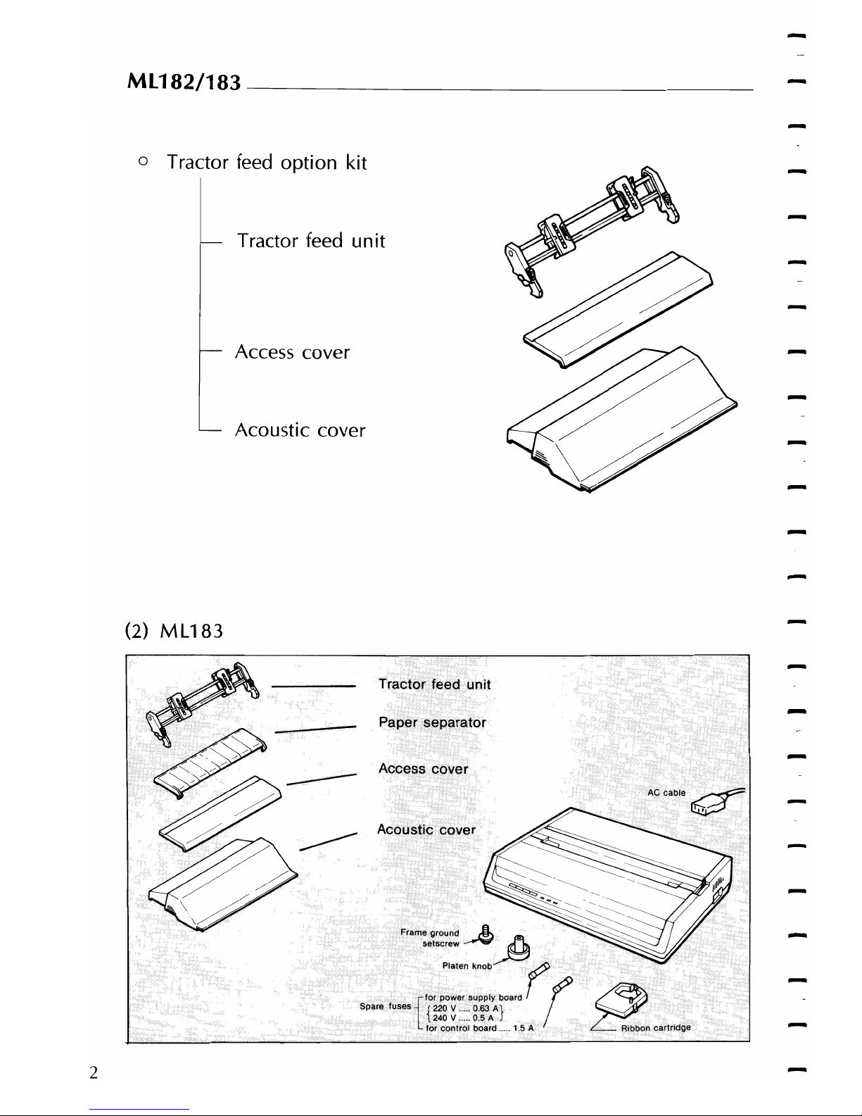
o Tractor feed
option
kit
Tractor feed
unit
Access cover
Acoustic cover
(2)
ML183
Tractor
feed
unit
Paper
separator
Access
cover
ACcable
~
~
Acoustic cover
Frame
ground
A
th
setscrew
~
Platen
knob
(
~for
power
supply
board
Spare
fuses:
{220 V ...
,.
0,63
A}
r
~
~'--'J
240 V 0.5 A Ribbon
cartridge
L for
control
board .....
15
A
2
Page 11

____________
CHAPTER
1
SETTING
UP
Optional equipment available for both the ML182
and
ML183
include:
o
Interface
equipment
Super-Speed
(19,200
baud) RS232C serial
board
High-Speed (9,600 baud)
RS232
C serial board
(M
L 182 only)
-
Super-Speed
(19,200
baud) RS422 serial
board
High-Speed
(9,600
baud) RS422 serial
board
(ML182
only)
Current-loop
serial
board
Let's begin:
1.
Do
not
plug
in
your
printer yet. That step comes later.
-
3
Page 12
-
ML182/183
________________
_
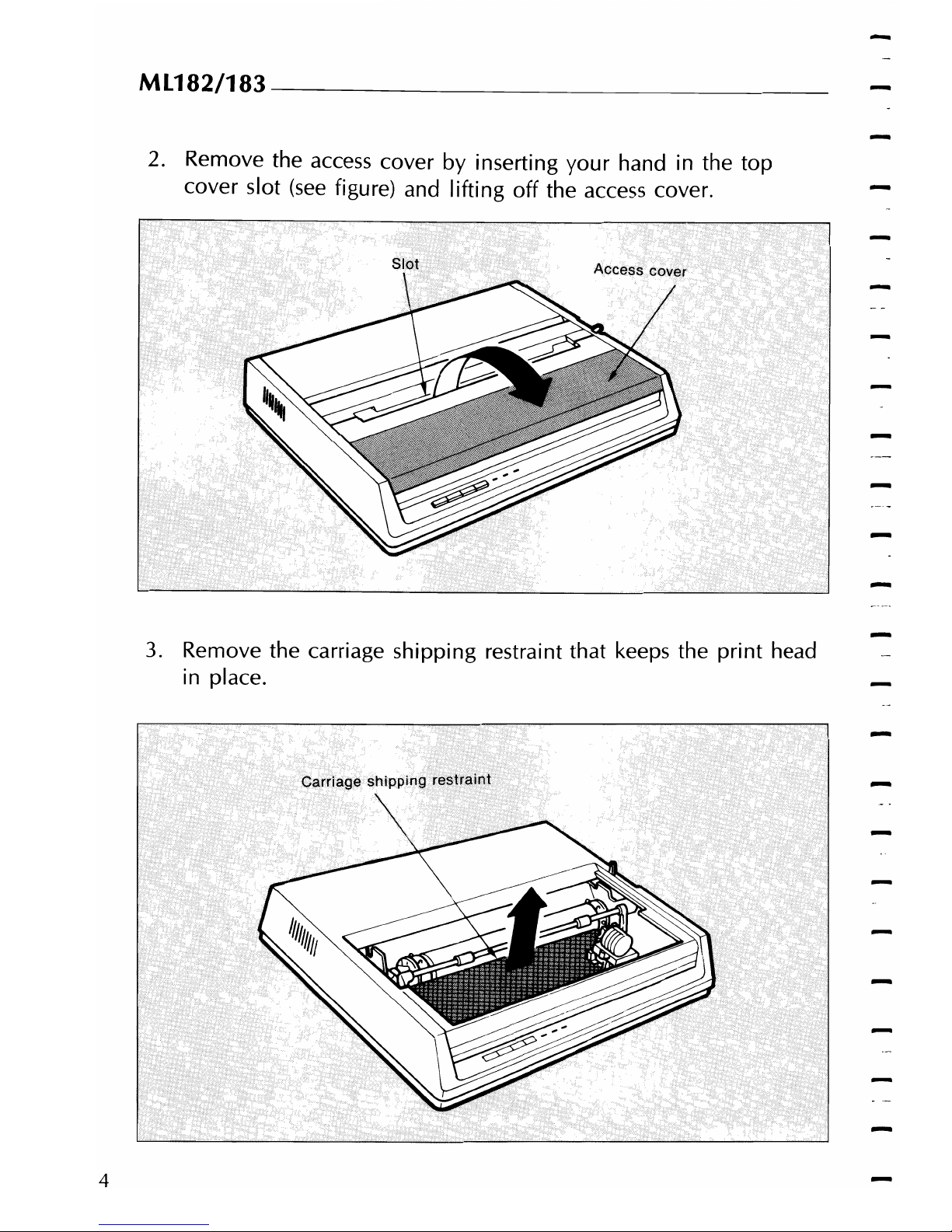
2. Remove the access cover
by
inserting
your
hand in the top
cover slot
(see
figure) and lifting off the access cover.
3.
Remove the carriage shipping restraint that keeps the
print
head
in place.
4
Page 13
___________
CHAPTER
1
SETTING
UP
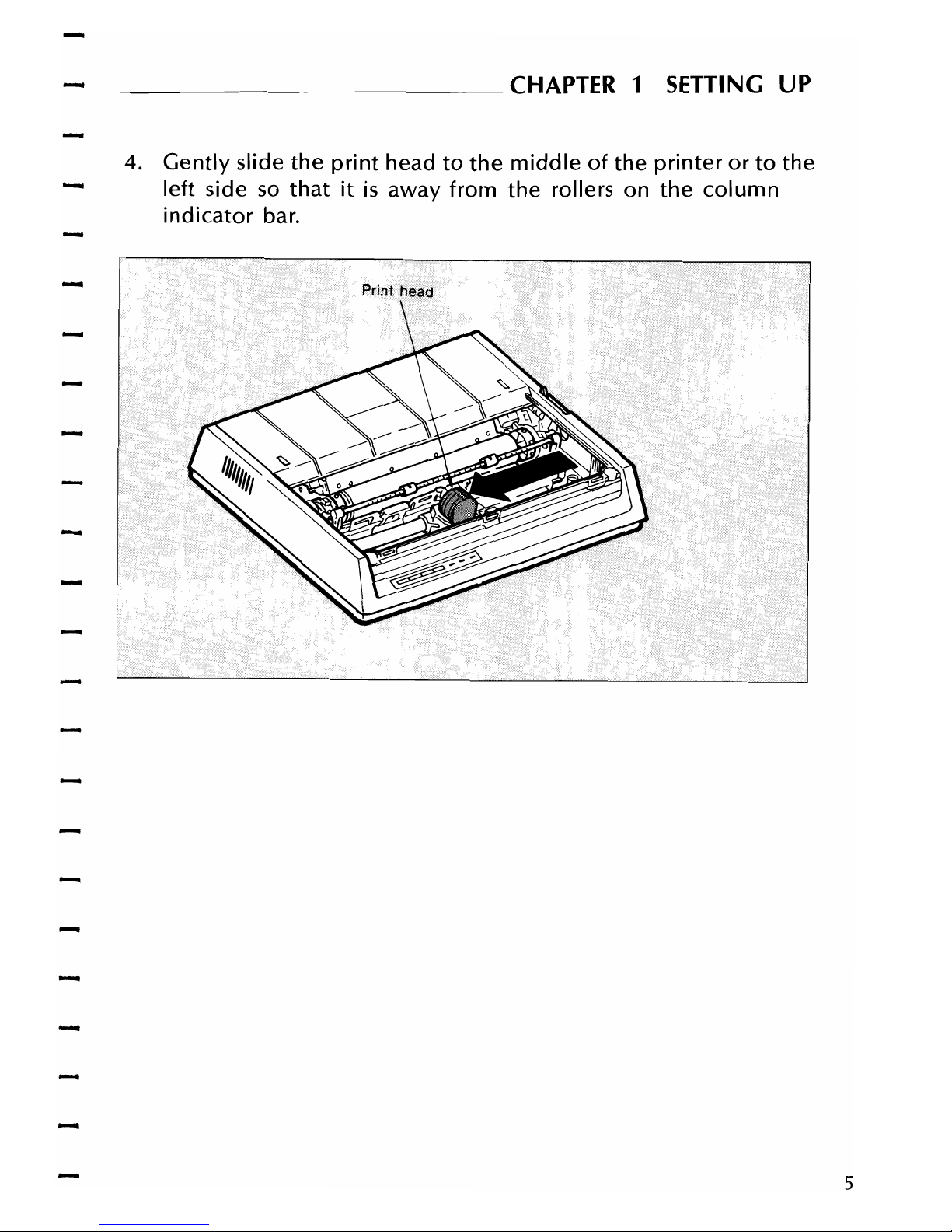
4.
Gently
slide
the
print
head
to
the
middle
of
the
printer
or
to
the
left
side
so
that
it
is
away from
the
rollers on
the
column
indicator
bar.
-
-
5
Page 14

ML182/183
________________________________
__
5.
Place the black ribbon cartridge on the ribbon cartridge holder.
The easiest method
is
to
tilt
the back
of
the cartridge
so
that it
slides into the area
of
the plate that
is
nearest the front
of
the
printer, then
lower
the
top
of
the cartridge (where the plastic
ribbon shield
is
located) over the
print
head. The tabs on both
side
of
the cartridge should align perfectly
with
the inserts on
-
the print head plate.
CAUTION:
Use
only genuine OKI ribbon cartridges
in
your printer.
Do
not
remove the ribbon shield.
Ribbon
Ribbon
cartridge
holder
6
Page 15

___________
CHAPTER
1
SETTING
UP
6.
Press
gently
on
the
cartridge
until
you feel
it
snap
into
place. To
remove
the
ribbon
cartridge, make sure
the
print
head
is
away
from
the
rollers,
then
grasp
the
cartridge
on
both
sides
of
the
print
head and
lift
up.
7.
The blue lever located to the left
of
the ribbon cartridge
is
used
to adjust the print head gap for single-
or
multi-part paper.
-
When single-part paper
or
two-part paper
is
in the printer, slide
the blue lever toward the
print
head. To print on three-
or
four-
part paper, slide the lever away from the print head.
-
-
7
Page 16
-
ML182/183
________________________________
__
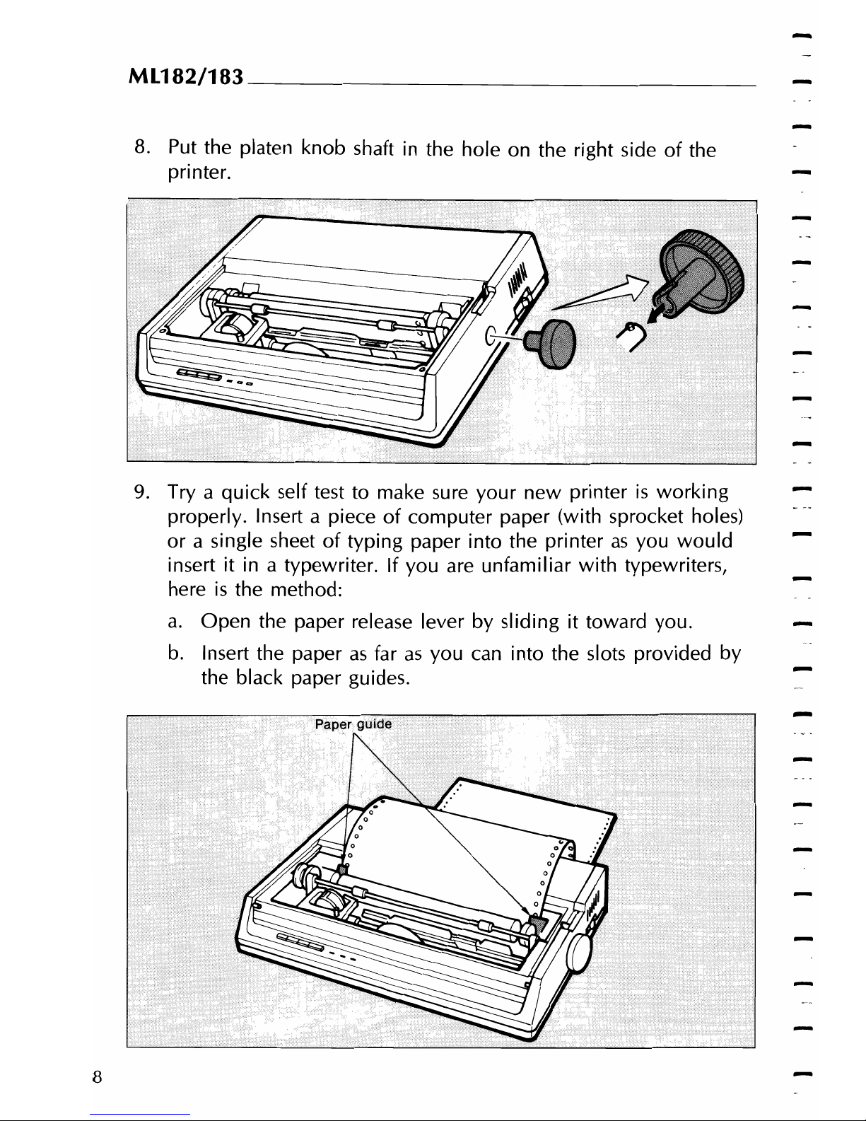
8.
Put
the platen knob shaft in the hole on the right side
of
the
printer.
9.
Try
a quick self test to make sure your new printer
is
working
properly. Insert a piece
of
computer paper (with sprocket holes)
or a single sheet
of
typing paper into the printer
as
you
would
insert
it
in a typewriter. If you are unfamiliar with typewriters,
here
is
the method:
a.
Open the paper release lever by sliding
it
toward you.
b.
Insert the paper
as
far
as
you
can
into the slots provided by
the black paper guides.
-
-
8
Page 17

-----------
CHAPTER
1
SETTING
UP
c.
Close the paper release lever.
d.
Turn the platen knob away from you to pull the paper
around the platen and behind the column indicator bar.
e.
Move
the column indicator bar back onto the platen
so
that
the rollers
rest
on the paper you just inserted.
-
10. Advance the paper, using the platen knob, until 1 inch
of
paper
appears above the column indicator bar.
11. Replace the
access
cover:
a.
Insert the three tabs in the edge
of
the
access
cover into the
holes on the top front edge
of
the
printer"
b.
Lower the
access
cover onto the printer.
12. Grasp the paper and pull it through the opening
in
the
access
cover.
Use
the platen knob
if
you need more paper.
13. Insert the connector end
of
the power cord into the plug on the
left side
of
the printer back.
14. Make absolutely certain that the ON/OFF
power
toggle switch
on the side
of
the printer
is
OFF.
(A
sudden power surge
can
damage the printer.)
15. Plug the power cord into a grounded (three-pronged) electrical
outlet.
CAUTION: The
printer
must be
groundedatall times. Do
not
avoid
the grounding
plug
by using a
three-to-two
prong
conversion plug.
-
-
9
Page 18

MU82/183----------------------------------
16. To print the self test, hold
down
the
LF
(line feed) switch
(located on the front panel) and turn the power switch
ON.
When the printer turns on (indicator lights), release the
LF
switch.
17. The
following
test pattern
will
be
printed, beginning
with
a
printer revision number that
is
followed by a rolling character
pattern.
ABCJ.')f;:FGHI JKLMNOPQRSTUVWXXZ
(\l""_'
a~edefgh
ij
k
BCDEFGHI
JKLMNOPQRSTUVW.XYl
[\J
.....
_
'abcqlFfgh
ij
kl
CO(::r=S.f+I
JKLMNOPQRSTUVWXYZ(\
J
....
_ •
ab~defgh
i j k 1
TIl
OEFt3HIJKLMNOPQRSTUVWXY,21·C\J
......
_
'abcdefgh
ij
k 1
rill",
EfGH·I
JKLMNOPQRSTUVWXYl
C\J
A
_.
abcdefgh
i j k 1 mnQ
FGHIJKLMNOPQRSTUVWXYZc,j"'"
•
abcdefgh
i j k 1 r.lYi':'p
NOTE: During self test printing, the SELECT indicator is out.
-
-
10
Page 19

___________
CHAPTER
1
SETTING
UP
18. To stop the test,
press
the
SELECT
switch (located on the front
panel)
or
turn the
power
switch OFF.
After the printer
has
shown that
it
is
in operating order, you are
ready to connect
your
computer. First, you need
an
interface cable.
-
If
you
don't
have one,
see
your
computer dealer or,
if
you have the
equipment, make
your
own
cable using the instructions in
Appendix
-
C.
-
11
Page 20

Ml182/183
________________
_
CONNECTING
YOUR
COMPUTER
You should have either a parallel or serial interface cable to connect
your
computer to
your
ML
182 IBM-compatible printer. Before you
connect the cable, make sure both printer and computer
power
is
OFF.
Connecting a Parallel Interface
1.
Insert the 36-pin
plug
in the appropriate receptacle toward the
right side
of
the printer back.
If no frame ground
(FG)
included in
your
interface cable, con-
nect a frame ground
wire
from the
computer
to the frame
ground connection hole at the back
of
the printer using the
setscrew attached to the printer.
-
-
.•
~
r:
Frame.
...........
~grounl\l
~..
.
.•.•........ . c.
on.
n(;lctiorT
\ hole
-
\)_
\Frame
Frame.
,:..
ground ground wire
\.
:;:
s.etsorew
"':.::.-'
-
12
Page 21

___________
CHAPTER
1
SETIING
UP
2. Snap the
two
wire
clips
onto
the plug.
3.
Insert the other end
of
the cable into
your
computer. You may
also connect
it
to'another
peripheral device, such
as
a disk
drive,
if
your
equipment
is
designed for
"daisy-chain"
connection.
-
4. Turn on the
equipment
and try the one-line program shown
below, using the proper print statement
for
your
computer (the
example
uses
LPRINT). (Make sure you have paper and ribbon
in the printer.)
5.
Type: LPRINT "Everything's
okay"
and then run the program.
6.
Your printer should print "Everything's
okay"
at 10 characters
per inch.
NOTE: If the printer did not print, make sure you entered the program properly. Some
computers require that you assign
a number
to
the printer and specify that number in
your print statement; for example
OPEN
# 3 means the printer
is
on
line # 3
to
the
computer.
7.
Now
try this program (change it,
if
necessary, to suit
your
com-
puter's requirements):
10
LPRINT "EVERYTHING'S
OKAY"
20
LPRINT "THIS LINE SHOULD
BE
SPACED 1/6"; CHR$(34);"
UNDER THE FIRST"
8. The printout should look like this:
,tVERYTHING'S
OKAY
TH
I S
LI
NE
SHOULD BE SPACED .11
E."
UNDER THE
FIRST
13
Page 22

Ml182/183
________________________________
__
If
it
is
overprinted, make a small adjustment to the printer
so
that
it
automatically inserts a line feed at the end
of
a line,
-
because
your
computer does not supply the line feed.
(See
page
18 for details.)
Serial Interfaces
-
The
optional
High-Speed RS232-C serial
interface
can run
up
to
9,600
baud
using Printer
Ready/Busy
protocol.
And
the
$uper-
Speed
board
has a
maximum
speed
of
19,200
baud
with a choice
-
of
either
printer
Ready/Busy
or
X-ON/X-OFF
protocol.
Before connecting
your
interface cable, make sure both
your
printer
-
and computer are
off before inserting the cable. Important to note
if
you
are
using a serial cable, you are probably required to
use
an
OPEN and
PR
# 1 statement in BASIC programming instead
of
LPRINT. Consult
your
computer documentation for details.
Connecting a Serial Interface
1.
Insert the 25-pin plug in the receptacle at the right on the
printer back.
2. Tighten the
mounting
screw on each side
of
the connector shell
so
that
it
is
securely attached to the printer.
3. Insert the other end
of
the cable in
your
computer. You may
also be able to connect the cable to another peripheral device,
such
as
a disk drive,
if
your
equipment accommodates "daisy-
chain"
connection.
-
14
Page 23

___________
CHAPTER
1
SETTING
UP
-
-
-
/
/'
~"W
4. Make sure you have a ribbon cartridge and paper in the printer.
5.
Turn
ON
the
power
and try this one-line program to make sure
the connection
is
correct:
LPRINT "Everything's
okay"
NOTE: Your computer may require a different
print
statement, such as PRINT # 1
or
PR
#
1.
Check your computer documentation for details.
6.
Run
the program;
your
printer should print this at 10 characters
per inch:
15
Page 24

-
ML182/183---------------------------------
-
7.
Now
try this program (modify
it
to suit
your
computer
requirements):
-
LPRINT
"Everything's
okay"
LPRINT
"This
lin~
should be spaced
1/6"
under the
first"
-
-
8. The
printout
should
look
like this:
-
-
E.}:erl-yt h
i:g'~,s
o~~y
This
line
should
be
-
-
9. If it
is
overprinted, make a small adjustment in the printer
so
that
it
automatically inserts a line feed
at
the end
of
a line,
because your computer does not supply the line feed.
(See
page
18 for details.)
16
Page 25

-
-
___________
CHAPTER
1
SETTING
UP
SETTING THE INTERNAL SWITCHES
Underneath the small cover on the top
of
the printer are eight
tiny
switches that
allow
you to select a specific language and to make the
printer meet the requirements
of
your
computer. This section
-
describes the switches and their factory settings.
If
you need to
change the settings,
follow
the instructions below.
17
Page 26
ML182/183
________________________________
__
-
NOTE:
If
you have the optional interface board installed, this switch bank
is
located
on the lower board.
-
Switch 1 selects
either
¢/¢
or
¢/¥
character
set
in
the
location
of
I
BM
character
set
(9
B)
Hand
(9 D) H respectively,
depending
on
the
setting. Set
to
OFF,
the
printer
will
power
up
in
the
'PIC/>
character
set.
And
set
to
ON,
the
printer
will
power
up
in
the
¢/¥
character
set.
-
It
is
recommended
that
you
set
the
printer
to
print
the
character
set
you
will
be
using
most
often.
-
Switch 2
is
set in the OFF position and establishes 10
CPI
as
the
default character pitch; in the
ON
position, 17.1
CPI
is
established
as
the default character pitch.
-
Switch 3 controls the automatic line feed. It
is
set
in the OFF posi-
tion because the IBM Personal Computer automatically sends a car-
riage return
to
the printer
at
the end
of
each line.
Set
in the
ON
position, switch 3 provides automatic
double
spacing.
-
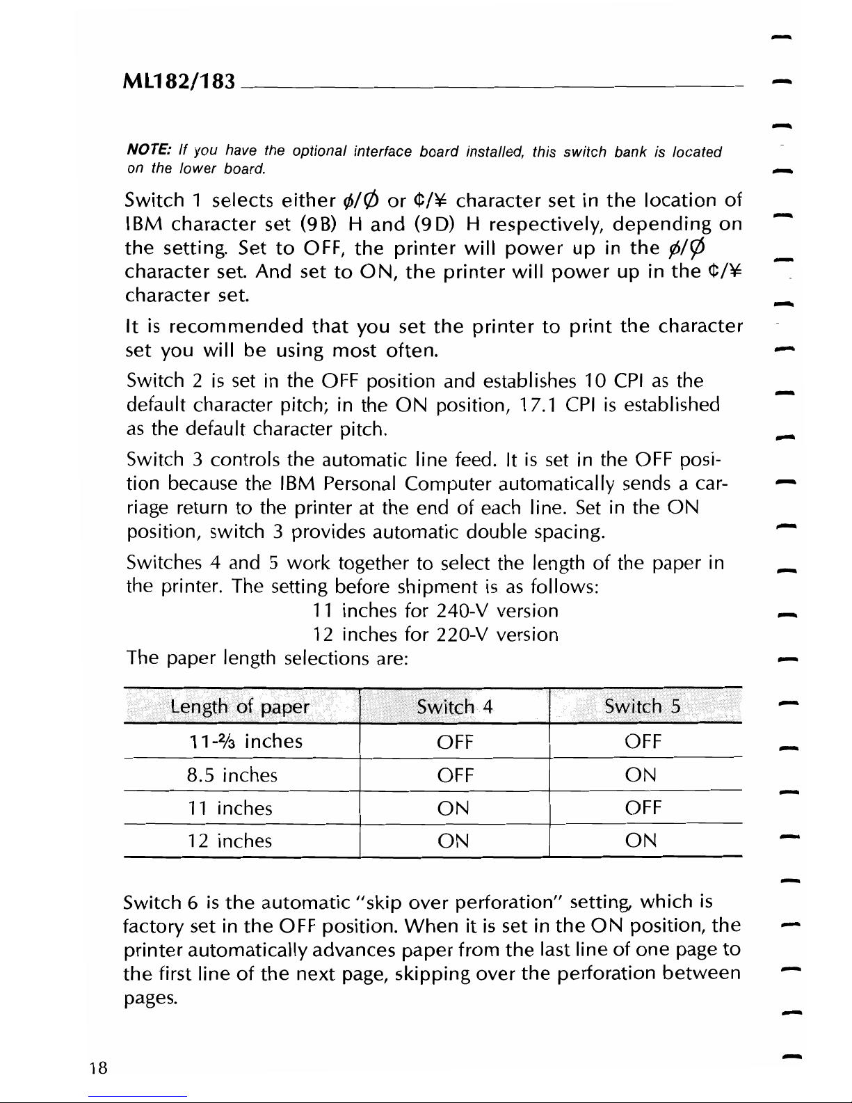
Switches 4 and 5
work
together to select the length
of
the paper in
-
the printer. The setting before shipment
is
as
follows:
11
inches for 240-V version
-
12 inches for 220-V version
The paper length selections are:
11-213
inches
8.5 inches
11
inches
12 inches
4
OFF
OFF
ON
ON
-
-
OFF
ON
OFF
ON
-
Switch 6
is
the
automatic
"skip
over
perforation"
setting,
which
is
factory set in
the
OFF position.
When
it
is
set in
the
ON
position,
the
printer
automatically
advances
paper
from
the
last line
of
one
page
to
the
first line
of
the
next
page,
skipping
over
the
perforation
between
pages.
18
Page 27

___________
CHA~TER1
SETTING
UP
Switch 7 selects
the
character set. This switch
is
factory set in
the
0 N
position and establishes character set
II
as
the
default
character
set.
In
the
OFF
position, character set I
is
established
as
the
default
character
set
- Switch 8 selects a programmed memory,
which
is
an
internal
ROM
in a
CPU
or
an external ROM. The factory setting
is
for
the
external ROM.
The
factory
switch settings are:
(1)
220-V
version
SWit(:h
Selection
Se~ting
;
1
¢/¢
OFF
-
2
10
CPI
OFF
3
NO
AUTO
LF
OFF
4
12 inches
ON
5
ON
6
NO
SKIP OVER PERFORATION
OFF
7
CHAPACTER
SET
II
ON
8
128K
ROM
OFF
(2)
240-V
version
2
10
CPI
OFF
3
NO
AUTO
LF
OFF
4
11
inches
ON
5
•
OFF
6
NO
SKIP OVER PERFORATION
OFF
7
CHARACTER
SET
II
ON
8
128KROM
OFF
19
Page 28
MU82/183
________________________________
_
To reset
the
switches, proceed
as
follows:
1. Make sure
the
printer
power
is
OFF
and
the
power
cable
is
unplugged.
2.
Using a phillips-head screwdriver, loosen
the
screw on
the
switch
cover at the back
of
the printer.
3.
Use
a sharp-tipped instrument, such
as
a ballpoint pen or toothpick,
to
slide the appropriate switch(es)
to a new
setting.
4. Replace the switch cover and tighten
the
screw.
-
-
-
-
-
-
-
20
Page 29

CHAPTER 2.
- OPERATING YOUR
PRINTER
Page 30
-
-
-
-
-
-
-
Page 31

CHAPTER 2 OPERATING
YOUR
PRINTER
SWITCHES,
LEVER,
AND
INDICATORS
Before you
use
your printer, it may
be
helpful to summarize the
switches, lever, and indicators on the printer and to consider the
various methods
of
loading paper.
On
the front panel
of
the printer, there
are
four switches,
two
of
which
were briefly introduced in the setup procedure.
In
addition,
there
are
three indicator lights that show the status
of
the printer.
POWER Indicator:
SELECT
Switch:
SELECT
Indicator:
Indicates that
the
printer
power
is
turned
ON.
Pressing this switch after the
printer
power
is
ON
places
the
printer
in deselect mode)
not
communicating
with
the computer. To return
to
select mode) simply press this switch again.
Pressing this switch also stops the self test.
Works
together
with
the
SEL
switch. Lights
when
the
printer
is
selected (ready
to
21
Page 32

ML182/183---------------------------------
receive data from the printer). The indicator
is
out when the printer
is
de~elected
and
duri ng self test.
TOF
Switch:
To
set
the first line position on each page
(top
of
form), deselect the printer and
press
this switch when the print head
is
at the
desired position. You can also select
17.1-character-per-inch printing
with
this
switch by
holding
it
down
when turning
printer
power
ON.
FORM
FEED
Switch:
To advance
the
paper
to
the
next page
(top
of
form),
press this switch
while
the
printer
is
deselected. You can also select
NLQ
(near
letter
quality,
page
76)
with
this
button.
Just
hold
down
the
FORM
FEED
button
while
you're
switching
on
the
printer.
ALARM Indicator:
Lights when paper supply
is
low
or ex-
-
hausted (unless you
use
the command to
disable the alarm, described on page 75).
Printing stops until the paper
~upply
is
replenished.
LINE
FEED
Switch:
If
you want to advance the paper one line,
press
this switch
while
the printer
is
deselected. It
is
also used to perform a self
test: turn
ON
the printer power
while
holding
down
this pushbutton.
The lever on the printer allows you to adjust the paper.
PAPER
LOCK/RELEASE
LEVER:
Open (slide forward) for inserting paper, for
adjusting paper, and when using tractor feed
computer paper. Close (slide back) for roll
paper and for single sheets.
PAPER
GAP ADJUSTMENT:
Slide toward the
print
head when inserting
single sheets, and away when using
-
multipart paper.
22
Page 33

___________
CHAPTER
2
OPERATION
PAPER
LOADING
You can load paper into the printer using several methods. If you
have a printer stand
with
a paper slot, you can load paper through
the bottom
of
the printer.
If
the printer
is
placed on a desk
or
table,
paper can be loaded from the top, like typewriter paper.
If
you have the optional roll paper stand
or
tractor feed unit, read
the instructions
below
covering
how
to install them and
how
to load
the paper.
When
you use fanfold paper, adjust the distance between the
sprocket pins at the ends
of
the platen correspond to the paper size.
You can adjust the platen pin
width
by
extending
or
compressing the
platen ends.
To move the platen end: Unsnap the lever, move the platen end to
the left
or
right, then close the lever.
Bottom
Feed
Paper Loading
1
Set
the printer on a slotted printer stand, carefully aligning the
slot in the stand
with
the opening in the base
of
the printer.
2 Place the box
of
paper under the printer stand.
3 Remove the access cover and
lift
the
column
indicator bar.
4 Open the paper release lever.
23
Page 34

ML182/183----------------------------------
5.
Insert the first sheet
of
paper in the opening in the bottom
of
the printer.
-
6.
Slide the paper up until it appears in front
of
the platen.
7.
Lower the column indicator bar.
S.
Close the paper release lever.
9.
Use the platen knob to advance the paper to the first printing
line.
10. Replace the
access
cover.
24
Page 35

____________
CHAPTER 2 OPERATION
Rear
Feed
Paper Loading:
1.
Set
the printer on a desk
or
table.
2.
Place the box
of
paper behind the printer.
-
3.
Remove the
access
cover and
lift
the
column
indicator bar.
4.
Open
the paper release lever.
5.
Insert the first sheet
of
paper in the paper guides.
6.
Push
the paper in just enough that
its
sprocket holes engage the
sprocket pins located
on
the platen ends.
7.
Turn the platen knob to advance the paper until
it
appears in
front
of
the platen.
8. Lower the
column
indicator bar.
9. Close the paper release lever.
25
Page 36

ML182/183
________________________________
__
10. Use the platen knob to advance the paper to the first printing
line.
11. Rep/ace the
access
cover.
-
26
Page 37

____________
CHAPTER
2 OPERATION
INSTALLING
AND
USING
THE
ROLL
PAPER
STAND
1.
Remove
the
access cover.
2.
Insert
the
tabs into
the
slots
on
both
sides of
the
printer.
~~"
3.
Plug
the
roll
paper
stand
cord
into
the
connector
for
the
paper-near-end
sensor at
the
rear of
the
printer.
27
Page 38

ML182/183
___
_
4.
Pull the ball arm lever forward to move the column indicator
away
from
the platen.
5.
Place
the paper release lever in the forward (open) position.
6.
Insert
the
paper shaft in the roll paper core, and
open
the
sheet
guide
of
the
roll
paper stand.
Mount
the
shaft on the
stands
so
the
grooved end
of
the
shaft fits
into
the
groove on
the
left
stand, and
the
paper rolls
from
the
bottom.
-
-
-
7.
Insert
the
paper
from
the back
of
the
platen,
making
sure its
edges lie
within
the
platen ends. (The sprocket pins
would
tear
it!)
8.
Push
the
paper in slightly.
Now
turn
the
platen
knob
to
bring
-
the
paper
to
the
front
of
the
platen.
28
Page 39

------------
CHAPTER 2 OPERATION
9.
Pull
the
paper supplied
to
the
front
of
the
platen in Step 8
through
the
slit between
the
indicator
and
the
platen, align
the
front
ends
of
the
roll
paper along
the
feeder side, and
close
the
release lever.
10.
Close the bail arm lever.
-
11.
Replace
the
access
cover: Fit
the
cover tabs
into
the
slots at
the
printer
front.
Next
lower
the
cover carefully, making
sure
the
paper fits
into
the
slot in
the
access
cover.
12.
By
turning
the
platen
knob,
move
the
paper
to
the
point
where
you want
printing
to
start. (Remember that many
word
processing packages automatically
allow
for a top
margin
of
25.4
mm
(1
inch).)
29
Page 40

ML182/183-----------------------------------
-
INSTALLING
AND
USING
THE
TRACTOR
FEED
UNIT
1.
Remove the access cover that came
with
your
printer.
2. Insert the posts in each end
of
tractor feed
unit
into the concave
of
the side frame.
3. Pull both sides
of
the tractor toward the
front
until the clamps
snap
into
both platen ends.
4. Install the paper separator
by
placing its hooks in the slots pro-
vided on the printer body.
-
-
30
Page 41

-----------CHAPTER
2 OPERATION
5. Load the paper from the top
of
the printer,
or
load it from the
-
bottom
if
you have a slotted
print
stand.
-
-
-
-
31
Page 42

ML182/183--
__________________________
__
6.
Adjust the left tractor
if
necessary; be sure it
is
no more than
12.7
mm
(1/2 inch) to the right
of
the left end. To move the
tractor, pull the lock lever open, slide the tractor to the desired
position, then push
it
to lock
it
in place.
7.
8.
Pull the paper under the
column
indicator and
up
to the level
of
the tractor unit.
Adjust the right tractor to the paper
width
by pulling the lock
lever open, sliding the tractor to the right
or
left (depending on
the paper size), and pushing the lock lever to lock
it
in place.
-
32
Page 43

-------------CHAPTER
2 OPERATION
9. Open the sprocket covers and the paper release lever (slide
forward).
-
-
-
10. Place the sprocket holes in the paper
over
the sprockets on the
tractor unit, making sure the paper
is
even.
-
-
-
33
Page 44

-
ML182/183--
______________________________
__
11. Close both sprocket covers.
12. Insert the access cover.
-
-
34
Page 45

-
-------------CHAPTER
2 OPERATION
-
INSERTING
SINGLE
SHEETS
-
1. Lift the column indicator bar.
-
2.
Raise
the paper separator
as
shown
in
the figure.
3.
Slide the sheet into the paper guides.
-
4.
Keep the paper release lever closed (slide back).
5.
Use the platen knob to advance the paper around the platen
-
and to the frist printing line.
6.
Lower the column indicator bar.
Now
you are ready
to
learn
about
programming
to
take advantage
of
the
special
printing
effects
of
your
ML182/183.
If
you
do
not
know
how
to
program, read
chapter 3 for a quick
explanation
that
may
help
you get started. If you have purchased a software package,
such
as
Lotus 1-2-3
or
WordStar, you may
find
some
pointers
in
-
chapter 3 on
how
to
program
the
IBM-compatible
ML
182/183
features
into
your
packaged software.
-
-
35
Page 46

-
-
-
Page 47

CHAPTER 3.
-
PROGRAMMING
Page 48

-
-
-
-
-
-
-
-
-
-
-
-
Page 49

CHAPTER
3
PROGRAMMING
Now
that
you
are
familiar
with
the
outside
of
the
printer,
you
can
begin
printing
documents
using
the
"default
settings"
of
the
pritner,
that
is,
the
kind
of
printing
your
ML182/183
is
set
up
to
do
when
you
turn
it
on:
Utility
mode*
10 characters per inch
6 lines per inch
Horizontal tabs at every 8th character
Vertical tabs at
l-inch
intervals
This may
be
all you ever need.
If you plan to print tables, charts, graphics,
or
documents
with
indented text, subscripts, superscripts, etc., however, you should read
this
chapter
to
learn
how
and
when
to
use
the
special
printing
features.
Fi
rst,
here are the avai lable pri nti ng options:
Carriage Return: If your computer does
not
automatically add
a carriage return at the end
of
a line, you
may add one to
your
program.
Unidirectional Printing:
With
this method, characters are printed
from left to right,
which
is
useful for tables
and charts where exactness counts.
Horizontal Tabs:
Sets
tabs at predetermined intervals; perfect
for accounting reports, tables, and charts.
Left Margin Set:
Changes the left margin for indented text.
Li
ne Spaci ng: Gives you a choice
of 6 or
8 lines per inch.
Formatting:
Adjusts printing
to
a particular paper size,
controls the line where printing begins, and
automatically advances the paper when
less
than 1 inch remains at the bottom
of
a
page.
See
skip over perforation function.
*:NLQ mode will be selected by pushing FORM
FEED
switch during power-up.
37
Page 50

M~82/183
________________________________
__
-
Skip
Over
Perforation:
If
you use fanfold paper
with
your
printer,
you may need to
use
this command to in-
struct the printer to automatically advance
the paper over the perforations.
Character Pitch: You can change from 10 to 12
or
17.1
characters per inch and you can also
double
the character
width
(10 characters per inch
to
5 characters per inch,
12
characters per
inch
to
6 characters per inch and 17.1
characters per inch
to
8.5 characters per
inch).
Enhanced/Emphasized: Prints characters in a
bolder
type,
common-
ly used
for
titles and subtitles.
Underlining:
Underlines a
word
or
group
of
words.
Character
Sets:
Choose from
two
different character
sets;
IBM character
set
either I
or
II
is
selectable
(see
page 56). There
is
also a switch selec-
tion
which
enables you to
power
up the
printer in either
set
and to establish the
default character
set.
APA Graphics:
Enables you to
draw
graphs, charts, and
pictures.
Cancel:
Clears the data in the print buffer.
What
you
do
next depends on whether you have invested in a soft-
ware package.
If
you have, skip
to
page
43
for advice on
how
to
add these features
to
your
prepackaged software.
If
you
do
not have
a software package, continue reading.
The printer
will
not
do
certain things unless you specifically tell
it
to.
You instruct the printer to change the
way
it
prints
by
sending
special codes through
your
computer.
When
you
write
a program,
you include the codes
for
printing features you
want
in
your
pro-
gram. In BASIC, for example, include them in
an
LPRINT statement.
-
-
-
-
-
38
Page 51

___________
CHAPTER
3
PROGRAMMING
BASIC
TRAINING
If
you
are
familiar with programming, skip this section and go
straight to the control codes starting on page
45.
Although
we
wrote our examples in MicroSoft's BASIC programming
language, the principles are similar for other languages. The examples
demonstrate
how
to
select a
few
of
your
printer's special
features and
try
them. Later
the
features are
explained
in
detail.
An
LPRI
NT
statement,
or
pri nt statement, tells the computer to
send
information to the printer. Take a minute to check your BASIC maual
to find
out
what form this takes in your version
of
BASIC.
Make sure
your
printer
is
ready to print (ribbon in, paper loaded,
power
ON,
SEL
indicator lit) and experiment a little
with
the print
commands.
1.
Type the
following
one-line program:
10
LPRINT
"WHO
YOU
GONNA CALL?"
2.
Press
ENTER,
then
RETURN
or
CR.
3.
The printer springs into action, printing this on the paper.
39
Page 52

-
ML182/183
________________
_
-
-
Computers cannot understand letters. They
use
only
numbers, more
specifically, binary numbers
(1
s and
as).
When carrying
out
an
-
LPRINT command, the computer
s.ends
the printer a code number
for each character (letter, symbol, punctuation mark)
within
the
-
quotation marks.
As
the printer receives each number,
it
prints the
-
dot
pattern associated
with
that number.
The American Standard Code for Information Interchange (before
-
known
as
ASCII)
is
the standard code
used
by
computers. Appendix
D gives the
ASCII
code numbers along
with
their hexadecimal,
-
binary, and decimal equivalents. You
can
enter these
ASCII
numbers
directly in your LPRINT statement by using the CHR$ (Character
-
Stri
ng)
function.
-
The CHR$ command
sends
the
ASCII
command in parentheses to
the printer.
For
example,
we
can
write a program this way:
-
LPRLI;:-lT·
CHR$(79);CH R$(75);CHR$(73);CHR$ (68);CHR$(65);
CHJ!$<84);
OtfR$
(65) .
;,:::",;'..
...
,)h
-
This
is
obviously a tedious way to write, but you need to understand
-
the concept when you
want
to
use
certain commands.
Keep in mind that there
is
a big difference between
ASCII
code
-
numbers and numbers that
are
printable characters.
For
example,
if
you want to print the number 1 using
an
LPRINT statement, you
-
would
type this:
-
LPRJ,,Il>jTCHR$(49)
You can also print numbers and symbols by putting them
within
-
quotes, like this:
-
[PRINT"1
"
So
far,
we have discussed printable characters, ASCII codes located
-
between decimal 32 and decimal 127. Non-printable codes, located
between a and 31,
do
not tell the printer to print something. They
instruct the printer
how
to print something. The ASCII chart in the
back
of
this handbook shows that these codes have abbreviations,
such
as
FF
and
US.
Some
of
these abbreviations make
sense
(FF,
for
instance, stands for form feed) but others
do
not unless you
are
a
telecommunications expert.
-
-
40
Page 53

__________
CHAPTER
3
PROGRAMMING
Let's try a few, starting
with
the ASCII non-printable code
US.
When
the
printer
receives
the
SO
command,
it
will
print
the
next
data
with
double
width.
10
LPRINT
"HELLO"
20
LPRINT CHR$(14);"HELLO"
Now
run the program. This
is
what you should get:
rt.e:(.l.O
HELLO
ASCII code
SO
is
non-printable,
so
you must
use
the decimal or hex-
adecimal form
of
the command
within
a CHR$ statement. Nothing in
quotes
will
work. Like most commands that change the way the
printer
is
printing, the
SO
(double width) command remains in effect
until either the end
of
a line
is
reached
or
you send a command to
cancel it.
See
what happens
if
you run the sample program a second
time:
HELLO
HELLO
41
Page 54

ML182/183
________________
_
-
-
The second time, the first
line
is
printed standard
width.
Because the
SO
command
is
not
in effect
by
the end
of
a line. To return to stan- -
dard size
printing
(10 characters per inch) you have
to
put
in
CHR$(30),
like
this: -
-
-
20
LPRINT CHR$(14);"HELLO";CHR$(20) " U U U HELLOW
AGAIN"
-
-
NOTE: U means space.
That
is
what
you
should get:
-
-
flfEL
LO
-
M.ELLO
HELLO·
H~H.~
N
-
-
To
avoid
any unpleasant surprises,
you
may
want
to insert codes at
-
the end
of a document
to
cancel
whichever
feature(s) you selected
and
to
reset the
printer
to the normal startup
condition.
-
ESCape Sequences
-
Many
of
your
IBM-compatible
MICROLIN E182/183
printer's
special
printing
features
are
controlled
by a combinaton
of
ASCII
codes
beginning
with
the
non-printable
code,
ESC.
Commonly
called
an
ESCape
sequence,
this
alerts
the
computer
to
interpret
the
next
code
number
as
part
of
an
instruction,
not
as a printable
character.
-
For
example,
if
you
want
to
put
tab
stops
at
every
fifth
column,
you
would
use
the
ESCape
sequence
ESC
D (5)
NULL.
(5)
is
binary.
-
Looking
at
the
ASCII
chart
on
page 129, this
is
how
you
would
change
the
horizontal
tab
command
into
BASIC:
-
-
42
Page 55

----------
CHAPTER
3
PROGRAMMING
10
LPRINTCHR$(27);CHR$(6'S);CliR$(f2);
or
10
LPRINT CHR$(27);/lA";CHR$(12)
This
is
just a
quick
overview
to
help
you get started
with
programm-
ing;
obviously
this
is
not all you need to know.
As
you become
more experienced
with
this handbook, you
will
find some shortcuts
and tricks
to
make programming even easier.
We
hope
we
have
given you enough information to get you started.
IF
YOU
HAVE A SOFTWARE PACKAGE
Software packages make the printer's special features, such
as
smaller
type fonts, subscripts, underlining, etc., much easier to
use.
To add
the features
to
your
package,
read
your
software documentation for
instructions, paying particular attention
to
any
limitations-for
exam-
ple, some software packages let you select a printing feature
for
an
entire document
but
do
not
allow
you
to
change features
within
a
document.
Other
packages may not accept the page formatting com-
mands, such
as
horizontal
tabs,
which
are
available
with
your
printer.
When
you
install
your
package,
you
probably
need
to
select
the
features
you're
going
to
be
using
from a list
called a "menu."
Several
software
packages
actually
list
names
of
printers
on
the
menu,
so
that
all
you
need
to
do
is
select
the
IBM
Graphic/5152
printer
from
that
list-the
software
package
will
then
automatically
use
the
commands
for
your
printer.
If
they
aren't
on
the
menu,
pick
the
closest general
description;
"Teletype
printer
that
doesn't
backspace"
is
often
the
best.
With
some
software
packages, such
as
WordStar'",
you
can easily
modify
or
install
your
program
to
accept
your
printer's
commands
by
inserting
codes
into
the
program. Still
other
software
packages
let
you
embed
commands
within a document
itself
by
preceding
the
command
with
"/OUT"
or
something
similar. VisiCalc'"
is a popular
package
that
provides a "setup"
option
as
part
of
the
printing
procedure-
you
simply
specify
at
the
beginning
of a document
what
printing
features
you
will
be
using.
43
Page 56

ML182/183--
______________________________
_
-
-
If
your
computer
is
equipped
with
BASIC, you have
an
alternative to
selecting features. After you load BASIC, run a simple one-
or
two-
-
line program telling the printer to change a feature(s).
Without
turning
the printer off, load and run
your
software package.
-
For example, suppose you wanted to
print
at 12 characters per inch:
-
1.
Load BASIC
-
2. Type the command: LPRINT CHR$(18)
-
NOTE:
You
do not have
to
know
how
to
program
to
do
this, but be sure to check
your computer documentation to see what statement to use
(we
use
LPRINT)
before
each command. Not all versions
of
BASIC are the
same.
-
3.
Press
ENTER,
then RETURN or
CR.
-
4.
Without
turning the printer off, enter
your
software package.
What
you just typed causes the computer to send a command to the
printer to go into 12 characters per inch mode.
When
you load and
run
your
software, all printing thereafter
will
be at 12 characters per
inch until you turn the printer
off
or
send a command to change the
characters per inch setting.
-
There
is
one
exception to this method, however: You cannot
use
this
method
if
your
computer
sends
an
"I-Prime"
signal before you load
-
a program. An
"I-Prime"
signal
is
sent by some computers to cancel
any special commands that were previously in effect
so
that you can
-
start fresh
with
each
new
document.
-
Basically
if
you are using a software package, just
follow
the instruc-
tions in the software manual
or
ask
your
dealer for the OKI
USERS
TIP that can help you. OKI publishes these instructions to make
set-
ting up and using various popular software packages
with
OKI
printers much easier.
-
-
-
-
44
Page 57

--------
CHAPTER
3
PROGRAMMING
PROGRAMMING
THE
M1182
For each printing feature explained in this chapter,
we
list three
dif-
ferent forms
of
each code
as
follows:
ESC
1
CHR$(27);CHR$(49)
1 B
31
Standard
Decimal code
Hexadecimal code
abbreviation in
presented in the
used by some
ASCII-used for
format most often
software packages
reference
used. A variation
to
enter
printing
of
the same
commands. A
command
is
variation
of
the same
CHR$(27);"1
II
command
is
CHR$
(&H1
B);
CHR$(&H31 )
CARRIAGE RETURN
AND
LINE
FEED
HexGl(leti
maf
CR
CHR$(13)
00
Carriage return tells the printer to
print
the line
of
data and returns
the
print
head to the left side
of
the page. IBM
PC
adds a line feed
after a carriage return unless 128
is
added to the command. If you
send a CHR$(141), therefore the result
is
a carriage return only.
'HexadeCimal
','
LF
CHR$(10)
OA
VT
CHR$(ll
)
OB
Line feed advances the paper one line; line spacing
is
1/6 inch
unless it
is
reset
using the command on page
47.
45
Page 58

Ml182/183
________________
_
-
-
HORIZONTAL
TABULATION
ASCII
ESC
DO
CH
R$(2
7);CH R$(68);CH
R$(O)
1 B 44 00
-
Horizontal tabs
are
set
at
every 8th character when power
is
first
-
switched
ON.
To eliminate the tab settings,
use
the
ESC
D 0
command.
-
HORIZONTAL
TABBING
-
ASCII Decimal
Hexadecimal
-
HT
CHR$(9)
09
-
Advances to the next tab position which occurs every 8th character.
The command
is
ignored
if
it exceeds the right margin
or
the max-
imum number
of
settings.
10
LPRI NT CH R$(27);CH R$(9);CH
R$(1
0);
20
LPRINT CHR$(9);"TAB"
-
30 LPRINT CHR$(9);"TAB
AGAIN"
-
TAB
TAB
AGAIN
-
-
-
-
46
Page 59

__________
CHAPTER 3 PROGRAMMING
LINE SPACING
The
default
line spacing for the
IBM-compatible
ML182/183
printer
is
6 lines
per
inch. This means
that
when
the
printer
power
is
turned
on,
the
spacing
from
the
bottom
of
one
line
to
the
bottom
of
the
next
line
on
the
same page
is
automatically
set
to
1/6
inch.
This
is
also
the
normal
spacing
of
a standard
typewriter.
You
can
change the line spacing to 8 lines per inch to fit more lines
of
printing per page, and for special effects, you
can
also vary line
spacing in multiples
of
1/72
or
1/126 inch. This affects space be-
tween lines only, not the height
of
the characters.
ASCII
DeCimal
Hexadecimal
ESC
0
CHR$(27);CHR$(48)
1 B 30
The
ESC
0 command
sets
line spacing to 1/8 inch.
ASCII
Decimal
Hexadecimal
ESC
1
CH
R$(2
7);CH R$(49)
1 B
31
The
ESC
1 command
sets
line spacing to 7/72 inch.
ASCII Decimal
Hexadecimal
ESC
An
CHR$(27);CH R$(65);
lB41
01-55
CHR$(l - 85)
The
ESC
A command
is
a user-selectable line space setting that
enables you to choose a setting in increments
of
1/72 inch. You
can
select a maximum line space setting
of
85/72 inches, which
is
the
equivalent
of
one printed line every 1-13/72 inches.
ASCII
.:..
Decimal
.....
Hexadeci mal
ESC
2
CH
R$(2
7);CH R$(50) 1 B
32
47
Page 60

ML182/183
________________________________
__
The
ESC
2 command implements the line spacing set by the
ESC
A
command. Should no
ESC
A command precede the
ESC
2 command,
the default line spacing
(6
LPI)
will
be activated by the
ESC
2
command.
FINE
LINE SPACING
ASCII
ESC
3 n CHR$(27);CHR$(51
);
1 B
33
01-FF
CHR$(l
- 255)
The
ESC
3 command
is
a user-selectable line space setting command
that lets you shoose a setting in increments
of
1/216 inch. You can
select a
maximum
line space setting
of
255/216 inches,
which
is
the
equivalent
of
one printed line every 1-39/216 inches.
(See
NOTE).
ASCII
DeCimal
dttRe~ad~cimal;
ESC
J n
CHR$(27);CHR$(74);
1 B
4A
01-FF
CHR$(l
- 255)
The
ESC
J command allows you to interrupt the
set
line spacing and
reset the line spacing for a single line to a
multiple
of
1/216 inch.
You
can
select a
maximum
space setting
of
255/216 inches,
which
is
the equivalent
of
a 1-39/216 inches line space.
Upon
receipt
of
the
ESC
J command, the printer prints
out
the line containing the command and advances the paper the distance specified by the command. Line spacing then returns to the previous setting, and the
printer continues to print.
(See
NOTE).
NOTES
TO
ESC 3 AND ESC
J:
The
standard IBM printer advance is expressed in
multiples
of
11216 inch. IBM-compatible MICROLINE hardware performs
paper
advances in multiples
of
1/144
inch rather than 11216 inch; therefore, MICROLINE
software automatically multiplies the
number
specified in ESC 3 and
ESC
J statements
by
2/3
to perform the most precise IBM emulation.
-
-
-
-
-
-
-
-
-
-
48
Page 61

__________
CHAPTER
3
PROGRAMMING
If the multiples specified in
your
ESC
3 or
ESC
J statements are not
evenly divisible
by
3, fine line spacing may
be
slightly more
or
slightly
less
than you specified.
If
the number you selected leaves a
remainder
of
1 when it
is
divided by 3, spacing
will
be slightly
less
than specified. If the number you selected leaves a remainder
of
2,
spacing
will
be slightly more than specified.
When
the number you
select
is
evenly divisible
by
3, fine line spacing
is
always exact.
The
ESC
A line spacing selection,
which
selects line spacing in
multiples
of
1/72 inch,
is
always absolutely precise.
PAGE
LENGTH SETTING
,
DEkimal
ESC
C n(n)
CH
R$(2 7);CH
R$(79);"67"
1 B 43 01-FF
CHR$(l
-127)
The
printer
page length set
is
user selectable in
either
inch
or
line
increments
where n is
either a two
or
three
digit
number. Selectable
line
length
settings range
between 1 to
127;
selectable inch
length
settings range
between 1 to
22. The
line
length
default
setting
is
66
lines
per
page
(11
inches)
with
a 6
LPI
line
spacing. You can also set
page length usig
the
internal
switch
settings (see page
17).
TOP OF
PAGE
ESC
S
CH
R$(2 7);CH R$(53) 1 B 35
The top margin on a page
can
be
set
by issuing this command.
Wherever the print head
is
at
the time this command
is
given
will
be
the first printing line. You
can
also
set
the top
of
page using the TOF
switch on the outside panel
(see
page 22).
FORM
FEED
Hexadecimal
FF
CHR$(12)
OC
49
Page 62

-
ML182/183--
______________________________
__
Prints the data in the print buffer, returns the carriage, then advances
the paper to the top margin
of
the next page.
NOTE
TO
TRS-80 OWNERS: This command
is
not valid with your computer.
SKIP
OVER PERFORATION
ASCII
ESC
N n
Decimal
Hexadeci mal
CHR$(27);CHR$(78);
1B2553n
CHR$(n)
(1
-127)
(01-FF)
If
n
is
any value between 1 and 127, the printer automatically ad-
vances to the top margin
of
the next page when there
is
only
1 inch
left
at
the bottom
of
a page. (This command
is
ignored
if
the value
of n is
more than page length.)
To stop the printer from automatically skipping to the next page (for
roll paper
or
forms longer than
12
inches),
11
equals
o.
In
BASIC format, the value
of
n must appear in a CHR$ statement.
CHANGING
CHARACTER
SIZE
ASCII
DC2
(10
CPI)
ESC
(12
CPI)
SI
(17.1
CPI)
SO
(double width)
DC4
(cancels
double
width
before line end)
ESC
W 1
(turns
double
width
on
permanently)
ESC
W 0
(turns
double
width
off
permanently)
Decimal
18
27 58
15
14
20
27
87
49
27
87 48
Hexadecimal
12
1 B
3A
OF
OE
14
1 B 57
31
1 B 57 30
-
-
-
-
-
-
-
-
-
-
50
Page 63

__________
CHAPTER
3
PROGRAMMING
The character size switches to 10 characters per inch
(CPI)
after the
printer receives the DC2 command. The character size becomes 12
CPI
when the
ESC:
command
is
received and 17.1
CPI
when the
51
command
is
received.
NOTE:
When
the
power
is
turned on while the
TOF
switch
is
depressed, the printer
is
set to 17.1
CPl.
You
can also set the printer to 17.1 CPI at power ON by setting
internal switch
2 to the condensed print mode.
The
printer will print in 17.1
CPI
until
power is turned OFF
or a command
is
sent to change the character size.
You can
double
the
width
of
10-, 12-, and 17.1-CPI print by insert-
ing the
US
command after the character size you want doubled. This
command doubles the size
of
characters that
follow
the command
on one line. The DC4 command can also
be
implemented on the
same line
as
an
SO
command. The DC4 command cancels double-
width
printing before the end
of
a line. This enables you to em-
phasize specific words
or
characters
within
a single line, and to
automatically return to your preselected type size.
The
ESC
W 1 and
ESC
W 0 commands override both DC4 and
SO
commands, and can
be
utilized to either permanently
implement
or
cancel
double-width
printing
within
a program
or
document. The
ESC
W 1 command implements
double-width
printing; the
ESC
W 0
command cancels it.
Character size can be changed in the
middle
of
a line unless
your
software package does
not
allow
you to
do
that. The table
below
in-
dicates the
maximum
number
of
characters per line in each character
size:
Maximum
Characters'~~t'l]ii~~
Size
ML182
MLla:J
10
CPI
DC2
80
136
12
CPI
ESC:
96
163
17.1 CPI
51
132
233
5
CPI
DC2
SO
40
68
6
CPI
ESC:
SO
48
81
8.5
CPI
51
SO
66
116
NOTE: Some forms
of
BASIC will
not
allow you to print more than
80
characters on
a line. Check your BASIC manual to see
if
you can override this limitation by using a
WIDTH
statement.
51
Page 64

ML182/183--------
________________________
__
-
10
LPRINT CHR$(18);"PICA
pica
10
cpi"
20 LPRINT CHR$(27);"ELITE
elite
12
cpi"
30 LPRINT CHR$(15);"CONDENSED
condensed
17
cpi"
40 LPRINT CHR$(18);"Back to
10
cpi"
50 LPRINT CHR$(14);"Double
pica"
60 LPRINT CHR$(27);"CHR$(14);"Double
elite"
-
70
LPRINT CHR$(15);CHR$(14);"Double
condensed"
-
-
-
leA
pica
E~~TE'l'lte
12
cpi
tfJtJENsEu'co~
11
cpi
ilack
to
10
mpi
D~··
...
'7'-
btl.
4!9
P.··:i.·~~"
-
.I)dI'ub
1.e
e
1.
i
t·~p
'>Double
condensed
-
UNDERLINING
-
~SClI
·'D
·······1··
;
eCll"lll~.
ESC
-1
CH
R$(2
7);CH R$(45) ;CH R$(l) 1 B
2D
01
ESC
-n
I CH
R$(2
7);CH R$(45);CH
R$(O)
1 B
2D
00
(n: even)
52
Page 65

__________
CHAPTER
3
PROGRAMMING
Use the
ESC
-n
(n:
odd) command to start
underlining a word
or
group
of
words. Use the
ESC
-n
(n:
even) command to stop underlin-
ing. The printer
will
continue to underline until the command
is
given to stop
it
(either
ESC
-n
(n:
even)
or
the printer
is
powered
down). (Because the underline
is
drawn by the ninth dot, the last
dot
in some descender characters
will
be overlapped.)
Underlining
under the spaces designated by horizontal tabs
is
available also.
10
LPRINT
"This
line
isn't
underlined"
20
LPRINT CHR$(27)"-";CHR$(1);"but
this
line is
underlined."
30
LPRINT CHR$(27)"-";CHR$(0);"This line
isn't
underlined."
This
line
isn't
underlined
but
this
line
is
underlined.
This
line
isn't
underlined.
SUPERSCRIPTS/SUBSCRIPTS
ASCII
Decimal
ESC
SO
CHR$(27);CHR$(83);
CHR$(O)
ESC
Sl CHR$(27);CHR$(83);
CHR$(1)
ESC
T
CHR$(27);CHR$(84)
Hexadecimal
1 B 58
00
1 B 58
01
1 B 54
53
Page 66

Ml182/183
________________________________
__
If you
want
to
print
superscript characters (characters appearing
above the normal
print
line), send the
ESC
SO
command before the
characters, symbols, or word(s)
you
want
printed in superscript. To
return to printing on the normal
print
line,
use
the
ESC
T command.
If you
want
to
print
subscript characters (characters appearing
below
the normal print line),
use
the
ESC
51
command before entering the
characters. To return
to
printing on the normal print line,
use
the
ESC
T command.
Superscript and subscript characters are printed in normal characters.
NOTE: Printing returns
to
the normal line when ESC
SO
is used
to
cancel subscript
or ESC
ST
is used to cancel superscript.
10 LPRINT
"This
is a ";
20
LPRINT CHR$(27);"S";CHR$(0);"superscript"
30 LPRINT
CHR$(27);"T";"This
is
a";
40 LPRINT CHR$(27);"S";CHR$(1);"subscript"
50 LPRINT
CHR$(27);"T";"This
is
back
to
normaL"
This
i1:>
a _
....
"._
....
_o
....
,,,.~
This
is
a
_ub_e
....
'"._
This
is
back
to
norMal.
-
-
-
-
-
-
-
-
-
-
-
54
Page 67

__________
CHAPTER
3
PROGRAMMING
ENHANCED/EMPHASIZED PRINTING
ASCII
Decimal
Hexadecimal
ESC
E
CHR$(27);CHR$(69) 1 B 45
ESC
F
CH R$(2 7);CH R$(70) 1 B 46
ESC
G CHR$(27);CHR$(71 )
1 B
47
ESC
H
CHR$(27);CHR$(72) 1 B 48
Enhanced printing provides a deeper resolution
of
each character
because each
dot
contained in a normal character
is
doubled ver-
tically, creating a darker impression. The
ESC
G command
is
a good
feature to
use
for headlines and subtitles and can be
used
in con-
junction
with
double-width
characters.
Emphasized printing, obtained by entering the
ESC
E command,
causes each character to be
doubled
horizontally, creating a bolder
image for titles, subtitles,
or
emphasizing word(s)
within
a document.
To return to the normal character
set
from emphasized mode, enter
the
ESC
F command. To return to the normal character
set
from
enhanced mode, enter the
ESC
H command. Neither feature
is
available for subscripts
or
superscript characters nor in line graphics.
Emphasized and enhanced printing can also
be
done
simultaneously
for special effects.
10 LPRINT CHR$(27);CHR$(71);"ENHANCED"
15
LPRINT CHR$(27);CHR$(72)
20
LPRINT CHR$(27);CHR$(69);"EMPHASIZED"
25
LPRINT CHR$(27);CHR$(70)
30
LPRI NT CH R$(27);CH
R$(71
);CH R$(27);CH R$(69);
"ENHANCED/EMPHASIZED"
35
LPRINT CHR$(27);CHR$(72);CHR$(27);CHR$(70)
55
Page 68

-
ML182/183----------------------------------
fiNHANCED
EMPHA$:IZIlD
ENHANCE
·
D.I.~fIliD
...
..
"
~,'V~
",)-":'f'
CHARACTER
SETS
i
-
Decimal,
ESC
6
CHR$(27);CHR$(54);
1 B
36
II
-
ESC
7 CHR$(27);CHR$(55); 1 B
37
If you
use
Spanish for all
your
documents. It
is
better to make the
-
selection on the internal switches
(see
page 17)
so
that the printer
-
normally
uses
that language.
-
56
Page 69

__________
CHAPTER
3
PROGRAMMING
BIT
IMAGE
GRAPHICS
Hexadecimal
ESC
K
CH
R$(2
7);CH R$(75) 1 B
4B
ESC
L
CHR$(27);CHR$(26)
1 B
4C
ESC
Y
CH
R$(2
7);CH
R$(89)
1 B
59
ESC
Z
CH
R$(2
7);CH
R$
(90)
1 B
SA
Using bit image graphics, you can
draw
almost any kind
of
illustration
with
your printer.
Bit image graphics
mode
enables
your
printer
to
"draw"
almost any
kind
of
illustration by
printing a dot
at any location
on
the page. Your
IBM-compatible MICROLINE will
work
properly
with
any graphics
software package designed
for
the I
BM
Personal
Computer
and
IBM
Graphics Printer.
No
software modification
is
required; images will be
printed
without
distortion.
If you have IBM DOS 2.0, you
can
use
a software package (or
BASIC commands such
as
CIRCLE,
LINE, and DRAW) to create
an
image on the display screen (your software
or
BASIC manual
will
ex-
plain how), then
"dump"
it onto the
page
via the
Prt
Sc
command
key on your computer. The next section, "Screen
Dumps,"
gives
some examples.
The section called "Programming Bit Image Graphics" explains
what
you need
to
know
in
order
to
write
your
own
graphics programs in
BASIC
without
using the screen
dump
method.
SCREEN
DUMPS
This IBM Personal Computer feature lets you print a reproduction
of
any image on your display screen. Simply
press
the SHIFT key and
the Prt
Sc
key
at
the
same
time; whatever
is
on the screen
will
be
printed on the
page.
57
Page 70

MU82/183----------------------------------
This section gives examples
of
the screen
dump
feature.
In
the first
example,
we
use
the
"pie
chart"
program on
your
Supplemental
-
DOS disk, and in the second,
we
create a design
with
BASIC
graphics commands.
NOTE: You must have DOS
2.0
to
use the Prt Sc key for screen dumps. Before you
try the examples, follow these steps:
-
1. Place the IBM DOS
2.0
disk in drive A and the Supplemental
DOS disk in
drive B of
your
computer.
-
2.
"Boot"
the system.
3. When the
prompt
sign
("A>")
appears, type:
'1~'HICSl,,~·CR
>
-
("<CR>"
indicates pressing the Enter key,
which
is
marked
with
an
angled arrow.)
4.
When
you
see
the prompt sign again, type:
BASICA'<:CR>
.
EXAMPLE
1:
Pie
Chart
When you
see
the
prompt
again after
following
the steps above,
type:
-
When the prompt returns, type:
<CR>
-
The program
will
tell you
how
to enter information, and when you
-
finish, the pie chart
will
appear on the screen. Then just
press
both
the SHIFT and the Prt
Sc
keys at the same time. That
is
all you need
to do. The printer
will
print the chart on the paper,
which
should
look
something like the figure on next page.
-
58
Page 71

__________
CHAPTER 3
PROGRAMMING
!PRIRTEMJ
~.~
....
??
Anothe~
Cha~t?
<y
o~
N)
FIGURE 1
Example
2:
BASIC
Graphics
In
this example,
we
use
the
DRAW
statement in
IBM
BASIC
to
create a pattern on the screen and then pri nt it out.
Other
statements
you can
use
include CIRCLE and LINE;
see
your
IBM
BASIC manual
for
details
of
how
these statements
work.
Keep in
mind
that a screen
dump
will
print
out
everything that ap-
pears on the screen
including
menus, prompts, error messages, etc.,
which
you may
not
want printed.
Our
sample program shows some
ways to suppress unwanted parts
of
the display.
If you just tried Example
1,
enter
"N"
when the program
asks
"Another
Chart?
(Y
or
N),"
then type NEW; this returns you
to
BASIC.
Enter the
following
program:
5 KEY OFF
10 SCREEN
1
15
CLS
20
DRAW"EMO,OR320D200L320U200"
30
DRAW"BM50,50R220D100L220U100"
40
DRAW"BM75,75R170D50L 170U50"
50 DRAW"BMO,OF400"
60 DRAW"BM320,OG400"
70
DRAW"BM160,OD200"
80
DRAW"BMO.100R320"
1 000 GOTO 1000
59
Page 72

-
ML182/183
----
_____________
_
-
-
PROGRAM
NOTES:
Line 5
erases
the display
of
function key values
so
they are not
printed.
-
Line 10 activates the medium-resolution graphics screen.
Line 15 clears the screen.
Lines
20
to 80 draw the pattern on the screen.
Line 1000
is
an
"infinite
loop"
that keeps the computer occupied.
If
you
omit
this line,
or
put
an
END statement in the program, the
screen
will
display a
prompt
sign when the program
is
completed.
If
you put in a
STOP
statement, the screen
will
display
"Break
in
-
1000."
In
these
cases,
the
prompt
or break message
would
also ap-
pear on
your
printout;
line
1000
in
our
program prevents this from
-
happening.
When
you
want
to stop the program after performing the
screen
dump,
press
the
BREAK
key.
RUN the program, and when the graphics pattern appears on the
screen, simply
press
the SHIFT and Prt
Sc
keys at the same time; the
printer
will
then print the image shown
below.
When you finish,
press
the
BREAK
key to stop the program.
-
-
-
FIGURE 2
-
-
60
Page 73

__________
CHAPTER
3
PROGRAMMING
PROGRAMMING
BIT
IMAGE
GRAPHICS
You
can
also
write
a program that prints a graphics image directly,
without
transferring it from the display screen. This section explains
how
to
do
this using BASIC statements.
Your printer prints graphics images in successive columns
of
eight
dots. The LPRINT statement that tells the printer to do this
has
three
components:
• The control code sequence that puts the printer into graphics
mode,
• The number
of
columns to be printed, and
• The coded data that tells the printer
which
dots to
print
in each
column.
First,
we
discuss each part separately, then put them together.
There are
four
modes
of
bit
image graphics available
with
the
IBM-compatible
MICROLINE. They
differ
in horizontal resolution,
or
density. This indicates
how
close together
the
dots are;
it
is
measured by the
number
of
dots
per
inch. All modes have a
vertical resolution
of
72
DPI. For reference,
the
diameter
of a dot
is
1/72 inch. The modes are discussed in
more
detail in
the
next
section
on
control codes.
The maximum
width
of
a graphics image
is
8 inches for the
ML
182.
1 . Control Codes
A graphics LPRINT statement begins with a control code that tells
the printer to print a graphics image.
Each
graphics mode
has
a dif-
ferent control code.
61
Page 74

-
Ml182/183
-
-
ESC
K
CH
R$(27);CH
R$(75)
1 B
4B
(hex)
Single
Density
60 x 72 DPI
-
ML182
ML183
Max.
dots/line
480
816
Max.
dot
res.
480
816
-
ESC
L CH
R$(27);CH
R$
(76)
1 B
4C
(hex)
Double
Density,
half
speed
120
x 72 DPI
-
ML182
ML183
-
Max.
dots/line
960
1632
Max.
dot
res.
960
1632
-
In
this
mode,
the
printhead
slows
down
so
it
can
print
dots
that
overlap
by
about
1/2
dot
width.
-
ESC
Y CH
R$(27);CH
R$(89) 1 B
59
(hex)
Double
Density,
normal
speed
120
x 72 DPI
ML182
ML183
-
Max.
dots/line
480
816
Max.
dot
res.
960
1632
-
This
mode
has
the
same
density
as
ESC L and
prints
at
normal
speed;
however,
you
cannot
print
dots
in
the
-
same
row
in
adjacent
columns.
In
other
words,
after
you
have
printed a dot
in
one
particular row,
you
can't
print
on
that
row
in
the
next
column.
-
ESC
Z
CH
R$
(27);CH
R$
(90)
1 B SA (hex)
Quadruple
Density
240
x 72 DPI
-
ML182
ML183
Max.
dots/line
640
1088
-
Max.
dot
res.
1920
3264
This
mode
prints
dot
columns
that
overlap
by
about
3/4
dot
width.
It
can
print
only
every
other
dot
on
the
same
-
row. In
other
words,
after
you have
printed a dot
in
one
particular
row,
you
can't
print
on
that
row
in
the
next
column.
-
-
62
Page 75

----------
CHAPTER
3
PROGRAMMING
NOTE: Take a minute
to
think through the restrictions
on
the
ESC
Y and
ESC
Z
graphics modes. Basically, it just means that you cannot print a horizontal line with
fully overlapping dots.
Even
with the skips, dots on the same row are close enough
together that
a line will appear solid.
You
can, however, print dots in other rows. This
allows you to create much finer curves and diagonal lines
in
these high-density
modes.
2.
Number
of
Columns
The "start graphics" code
is
followed
by
two
numbers
telling
the
printer
how
many columns to print. For
ease
of
reference, call these
numbers
nl
and n2.
To find the value
of
these numbers, determine
how
many columns
you want to print, then
divide
it
by 256. The value
of
n2
is
the in-
teger portion
of
the quotient, and the value
of
n 1
is
the remainder
expressed
as
an
integer.
63
Page 76

-
ML182/183----------------------------------
-
-
Example:
Suppose you want to print 400 columns
of
graphics:
-
n2=
1
-
256 ) 400
-
256
-
n1
= 144
-
If you
want
to print in single density graphics mode, the beginning
of
your statement should look like this:
-
-
-
-
IBM BASIC includes
two
functions that make calculating
n1
and
n2
-
very
easy:
•
MOD
divides
two
numbers and returns the integer remainder,
-
•
FIX
removes the fractional portion
of
a numeric expression
without
rounding it off.
See
your BASIC Manual for details.
Using these functions, you
can
express our sample numbers this
-
way:
O'!NDOTS=400
-
l T
$~~~~;C~~(7~Jfi::H~~DO~~
~:JP
··CHR$(FIX(NlQOTS/256»
-
IMPORTANT NOTE:
The
number
of
dot columns expressed by
n1
and n2 cannot be greater
-
than the maximum number
of
dot columns per line allowed for the graphics mode you are
using
(see
table below).
-
-
64
Page 77

__________
CHAPTER
3
PROGRAMMING
Maximum Graphics Columns Per
Line
<:;raphi~s
mo~e
ESC
K
(Single Density)
480
816
ESC
LIESe y
(Double
Density)
960
1,632
ESC
Z
(Quadruple
Density)
1,920
3,264
If the value entered
is
greater than the allowed maximum, the proper
maximum
value
will
automatically be entered.
3.
Graph ics Data
The last part
of
the graphics statement contains numeric data that
tells the printer
to
print
dots at specific positions in each column.
It
is
easiest
to
layout
your
image on graph paper,
filling
in the
squares where you
want a dot
to
appear. (If you
want
to
use
higher-
density graphics, keep in
mind
that the columns
will
overlap, and
remember any restrictions that may apply.) Then
divide
the image in-
to strips
of
eight rows.
Each
row
will
be programmed
as
a separate
LPRINT statement.
Each
position in the
column
has
a numeric value
as
shown in the
table below. Simply add the values
of
the
column
positions where
you
want
dots to appear, then enter the total in
your
LPRINT
statement.
IF
YOU
ARE
FAMILIAR
WITH
BINARY
NUMBERS: Each column is represented by an
8-bit
binary number. A dot represents a "1"
and
a space
is
"0"; the top dot is the MSB (most
Significant bit)
and
the bottom
dot
is the LSB (least significant bit). The
bit
positions are shown
in the table for reference. You can use the ASCII code chart in Appendix 0
as
a conversion
table.
65
Page 78

-
ML182/183--------
________________________
__
-
Column Position Values
-
.......
.,
....
.
....
[0ecimal
Value
'Column
~()sition
"
........•..
Bit
J
128
27
0
0
64 2
6
-
0
32
2
5
-
0
16
24
-
8
2
3
0
4
22
0
0
2
21
-
0
1
2°
-
Example:
-
-
Enter
asCI-JR$(93)
-
If
we
call the
number
for each
column
C1, etc., then the complete
statement looks like this:
R$(
R$(
R$
(1
$1~;eH
R$(
R$(
iCH
0)
l.\if,
column
data col. 1 ... col.
400
-
The format
is
the same for all density modesi the
only
differences are
in the "start graphics" code and in the
maximum
amount
of
column
-
data that can
follow.
The
number
representing any particular pattern
of
dots in a
column
is
the same regardless
of
graphics mode.
-
66
Page 79

__________
CHAPTER
3
PROGRAMMING
Putting it Together
Now
we can
work
through a simple example. Suppose
we
want
to
draw
two
diagonal lines.
As
drawn on graph paper, they
look
like
this:
Step
1.
Begin
with
LPRINT and the "start graphics" code
for
si
ngle-density graph ics:
r;;!;;j;~~\~iJ
0 LPR1;,T
Cltlg$(27);CHR$(75);i.f~ii;i;\
Step 2.
Count
the columns in the image. There are 11,
so
we
calculate
n1
and n2:
n2=
0
256 )
11
o
n1 =
11
and add them to the statement:
···!rOrp~iNT
•..
~HR$it~i.~HR$(~i~~iltlR$(.l!lj:·t:ii9I~$(O~rf
tj!}F".*
67
Page 80

-
ML182/183
________________________________
__
-
-
Step
3.
Next add the
dot
values for each column
and insert them in the statement:
-
-
10
LPRI
NT
CH
R$(27);CH R$(75);CH R$(11 );CI-I R$(O);CH
R$(1
);CH R$(2);
-
CH
R$(4);CH R$(9):CH R$(18);CH R$(36);CH R$(72);CH R$(144);CH R$(32);
CH
R$(64);CH R$(128)
-
-
-
Step
4.
Now
run the program. The result should
look
like this:
-
-
-
-
-
If
it does not, check your arithmetic and typing, then try
again.
-
Now
go back and change the "start graphics" code to dou-
-
ble density, half speed
(ESC
L):
-
20
LPRINT
CHR$(27);CHR$(76);CHR$(11);CHR$(0);CHR$(1);CHR$(2);
-
CH
R$(4);CH R$(9);CH R$(18);CH R$(36);CH R$(72);CH R$(144);CH R$(32)·
CHR$(64);CHR$(128) ,
-
-
-
-
68
Page 81

__________
CHAPTER
3
PROGRAMMING
Run
the program and compare:
Notice
that the angle
is
steeper and the
two
lines are closer together.
This
is
because each individual
column
now
overlaps the next one.
Notice also that
it
prints more
slowly,
although
with
this
amount
of
printing
the difference in speed may be hard to detect.
Now
try
double
density, normal speed
(ESC
V):
30 LPRINT CHR$(27);CHR$(89);CHR$(11);CHR$(0);CHR$(1);CH R$(2);
CH
R$(4);CH R$(9);CH R$(18);CH R$(36);CH R$(72);CH R$(144);CH R$(32);
CH
R$(64);CH R$(128)
Aside from printing speed, there should be no difference, because
the pattern does not include adjacent dots;
if
it had, some dots
would
have been skipped.
69
Page 82

-
M~82/183
________________________________
__
-
-
Finally, try quadruple density
(ESC
Z):
-
-
40 LPRINT CH R$(27);CH R$(90);CH R$(11);CH R$(0);CHR$(1);CH
R$(2);
CH R$(4);CH R$(9);CH R$(18);CH R$(36);CH R$(72);CH R$(144);
-
CH R$(32);CH R$(64);CH R$(128)
-
Compare the results:
-
#co
-
;
;
-
I
The angle
is
even steeper, and the
two
lines have merged
into
one
thick line because
of
even greater overlap,
-
Here
is
another sample program that
uses
a FOR-NEXT
loop
to
print
all the possible combinations
of
dots and spaces in numeric order:
05 'SAMPLE2
06
WIDTH "LPT1:",255
-
10 NDOTS = 256
12
'MAXIMUM
POSSIBLE COMBINATIONS
30
LPRINT CHR$(27);CHR$(75);
CHR$(NDOTS MOD 256);CHR$(FIX(NDOTS/256));
40
'START GRAPHICS 256 COLUMNS -
50 FOR
1=0
TO NDOTS-1
60 LPRINT CHR$(I);
-
70
NEXT I
73
LPRINT:REM LINE FEED
-
-
70
Page 83

__________
CHAPTER
3
PROGRAMMING
A
word
of
explanation
about
line
06: The IBM personal Computer is set for a maximum line
length
of
80 characters, so it adds a Carriage Return and Line Feed after the 80th character.
Because the data for each column is treated
as
a character, your computer will send
CR
and
LF codes after the data for the 80th column, and the printer will interpret these codes
as
graphics information and print them. A
WIDTH
statement changes the maximum length
of
a
line,
and placing the number 255 in a
WIDTH
statement eliminates any length restriction.
(See
your IBM BASIC Manual for details.)
The printout looks like this:
You can vary the length
of
the graphics line by changing the value
of
NDOTS.
Try changing the density in this program and
see
what
happens.
Save
this program; you
will
need
it
later.
Combining
Text and Graphics
You can
mix
normal text printing and graphics on the same line.
Here
is
an
example using the image coded in the last section:
05
'SAMPLE
3
10
LPRINT
"TEXT
PRINTING";CHR$(27);CHR$(75);CHR$(11);CHR$(0);
CH R$(1);CH R$(2);CH R$(4);CH R$(9);CH R$(18);CH R$(36);CH R$(72);
CH R$(144);CH R$(32);CH R$(64);CH R$(128);
"TEXT
PRINTING
AGAIN"
71
Page 84

M~82/183
________________________________
__
-
-
Here
is
the result:
-
-
The printer prints
normally
unti I
it
receives the "start graphics" code.
It then prints the number
of
graphics columns specified by
n1
and
n2 and automatically returns to normal printing.
NOTE: Be careful to enter the amount
of
graphics data you told the printer to expect;
otherwise the results will be garbled.
PRINTING MULTILINE GRAPHICS
One
LPRINT statement cannot
print
more than one line
of
graphics,
so
you have
to
enter a separate LPRINT statement for each subse-
quent line
of
graphics.
To illustrate this, add these lines to the SAMPLE 2 program:
-
-
-
This
loop
causes the LPRINT statement
to
be repeated four times.
Here
is
the result:
-
-
-
72
Page 85

__________
CHAPTER
3
PROGRAMMING
Notice that there
is
a space between each pair
of
lines. This
is
because the standard distance from the top
of
one line to the top
of
the next
is
1/6 inch,
but
a column
of
graphics
is
only
1/9 inch high
(8
dots x
1/72
inch per
dot
=
8/72
inch=1/9
inch). To
print
a con-
tinuous image
with
no
gaps
between the lines, you must
use
the
ESC
A command to change line height to
8/72
inch and
ESC
2 to activate
the change
(see
page
47).
Add these lines:
;;l~~;iLpRUNT
CH
(65);¢~R$(ar
l:¥cii)'lPRI'NT
CH
(50)
The modified program
now
looks like this:
05 'SAMPLE2
06
WIDTH "LPT1:",255
1 0 N DOTS = 256
12
'MAXIMUM POSSIBLE COMBINATIONS
15 LPRI NT CH R$(27);CH R$(65);CH
R$(8)
18 LPRINT CHR$(27);CHR$(50)
25
FOR J = 1
TO
4
30 LPRINT CHR$(27);CHR$(75);CHR$(NDOTS MOD 256);
CHR$(FIX (NDOTS/256»;
40 'START GRAPHICS 256 COLUMNS
50 FOR
I=OTO
NDOTS-1
60 LPRINT CHR$(I);
70
NEXT I
73 LPRINT:REM LINE FEED
75 NEXT
J
73
Page 86

ML182/183
----------------
The result looks like this:
-
-
-
-
Reminders
1.
Make
sure you have entered
column
data for the same
number
-
of
columns
as
specified
by
n 1 and n2 in
your
LPRINT state-
ment. If you enter
too
much
or
too I ittle data, the results
wi
II
be
garbled.
2. You can
print
no more than the
maximum
number
of
columns
for
your
graphics density
mode
(see
table on page 61). If more
data
is
contained in the LPRINT statement, the excess
will
sim-
ply
be ignored.
3.
Observe the limitations on
dot
placement in these graphics
density modes:
Double density, normal speed
(ESC
Y)
and
quadruple density (ESC Z): Skip at least
one dot position between dots on the same horizontal row.
The
printer will not print
a dot placed closer than this.
Hints
The ways you can
use
features
of
BASIC to program graphics are
limited
only
by
your
imagination and
your
programming experience.
In
this section
we
summarize the tricks used in the examples and
suggest a few
new
ones.
MOD
and
FIX
can
be
very helpful in calculating the
number
of
col-
umns
of
graphics data,
as
explained on page
64.
-
You can
use
the type
of
FOR-NEXT
loop
shown in sample 2 in some
cases
where
the
dot
pattern can be described
by
a mathematical
function; a straight line
or
a sine wave, for example.
-
74
Page 87

__________
CHAPTER
3
PROGRAMMING
To
simplify
typing the
column
data, you can enter the values in a
DATA
statement, then
use
a READ statement in a
loop
to
print
it.
Here
is
a model:
INT
$ (
[)O"S/~
5
6)
)'~1J2:~
40
FORI"" 1 TO
1\1
DOTS
50
D
G~/~;f?
601I\lT~~H
R$(C};
70
NEXTI
This method makes it easier
to
check and
modify
your
data. Using a
variable such
as
NDOTS
helps to make sure the
amount
of
data in
the program matches the
number
of
columns you have specified.
CANCEL
FUNCTION
CAN
CHR$(24)
18
The cancel code clears the printer buffer.
All
control codes remain in
effect until you give a specific command to change them
or
turn the
printer off,
with
the exception
of
SO
(double-width),
which
is
cancelled.
75
Page 88

-
ML182/183----------------------------------
-
LINE
FEED
"",'
ASCII
LF
Decimal
10
i
Hexadecimal
OA
VT
11
OB
Execution
of
the VT or
LF
command
causes
one line
of
data
to
be
printed, and also
causes
the paper to advance one line.
PAPER
OUT
-
ASCII
ESC
8
CHR$(27);CHR$(56);
1 B
38
-
ESC
9
CHR$(27);CHR$(57);
1 B
39
If you want to disable the paper out alarm (the paper indicator
will
not light when paper
is
low) enter the
ESC
8 command. If you want
to
be
signaled by the printer when paper
is
low
or out, (this
is
the
default setting)
use
the
ESC
8 command.
NEAR
LETTER
QUALITY
MODE
ASCII
-
ESC I ETX
(27)
(73)
(3)
(1
B)
(49)
(03)
When
you
want
to
make a
good
impression
with a memorandum
or
letter,
use
OKl's
special near letter
quality
mode. In this
mode
the
printer
prints over each line twice.
On
the
second
pass,
the
printer
fills in
the
dot
pattern
to
form
a sharp, crisp letter. You get great
results
when
you
print
your
word-processing files in this mode.
-
UTILITY
MODE
ASCII
ESC
I SOH
Decimal
(27)
(73)
(1)
Hexadecimal
(1
B)
(49)
(01)
-
The first
time
you
turn
your
printer
on,
it
will
automatically
print
in
utility mode. In this
mode,
the
printer
prints bidirectionally. This
printing
method
increases
the
printer's speed,
so
it prints
120
characters
per
second.
-
-
76
Page 89

APPENDIX A
Programming
Commands
Page 90

-
-
-
-
-
-
-
-
Page 91

APPENDIX
A
I
BM-COMPATI
BLE
ML
182/183
PROGRAMMING
COMMANDS
Description
CARRIAGE
RETURN
Prints data and returns
print head to the left
margin position.
HORIZONTAL
TAB
Tabs
to
next
horizontal
tab
stop
Cancels tabs
CHARACTER
SIZE
10
CPI
12
CPI
17.1
CPI
Double
width
Turns off
double
width
before end
of
line.
Turns
double
width
on
permanently.
Turns
double
width
off
permanently.
CLEAR
BUFFER
Resets
normal
width
ASCII
Decimal
CR
13
HT
9
ESC
D
NUL
27
68
0
DC2
18
ESC:
27
58
SI
15
SO
14
DC4
20
ESC
W 1
27
87 49
ESC
W 0
27
87
48
CAN
24
Hexadecimal
OD
09
1 B
4400
12
1 B
3A
OF
OE
14
1 B 57
31
1 B 57 30
18
77
Page 92

ML182/183
EMPHASIZED/EN HANCED
PRINTING
Doubles characters
ESC
G
27
71
1 B
47
vertically (enhanced).
Doubles characters
ESC
E
27
69
1 B 45
horizontally
(emphasized).
Cancels emphasized
ESC
F
27
70
1 B 46
printing.
Cancels enhanced printing.
ESC
H
27
72
1 B 48
FORMATING
Specifies the length
of
a
ESC
C n
27
67
n
1 B 43 n
page.
or
ESC C 00
m
27
67 00 m
1 B 43 00 m
Skip over perforation;
ESC
Nn
27
78
1 B
4E
advances paper when
less
than 1 inch remains at
bottom
of
page.
Cancels skip over
ESC
0
27
79
1 B
4F
perforation.
-
-
-
-
-
-
-
-
78
Page 93

ii
APPENDIX
A
PROGRAMMING
COMMANDS
...
Descriptio£)
ASCII Decimal Hexadecimal
GRAPHICS
Prints data in single-density
ESC
K
27
75
1 B 4B
bit image graphics mode;
60
X72
DPI.
Prints data in half-speed,
ESC
L
27
76
1 B 4C
double-dinsity bit image
graphics mode; 120X72
DPI.
Prints data in normal-
ESC
Y
2789
1 B 59
speed, double-density bit
image graphics mode;
120X72
DPI.
Prints data in quadruple-
ESC
Z
2790
1 B
5A
density bit image graphics
mode;
240X72
DPI.
LINE
FEED
Advances paper one line.
LF
10
OA
Advances paper one line.
VT
11
OB
LINE SPACING
Loads variable find line
ESC
An
27
65 n
1 B
41
n
spacing.
Sets
line spacing to
ESC
2
27
50 1 B 32
variable fine line spacing.
Set
the
line
feed to
7172
ESC
1
2749
1 B
31
inch
8
LPI
ESC
0
2748
1 B 30
Sets
the specified line
ESC
3 n
27
51
n
1 B 35 n
space.
Line spaces
n/21
6 inch
ESC
J n
27
74 n
1B
4A
n
79
Page 94

MU82/183
________________________________
_
Description
ASCII
Decimal
Hexadecimal
PAPER
OUT
ALARM
Paper indicator lights
ESC
9
27 57
1 B 39
whenever paper
is
low
or
out.
Pri
nter
wi
II
not respond to
ESC
8
27 56
1 B 38
a paper
out
condition.
Printer
will
continue
-
printing even
if
paper
is
out.
PRINT
MODE
NLQ
mode
ESC I ETX
27
73 3
1 B
49
03
UTI
LlTY
mode
ESC I SOH
27
73 1
1 B
49
01
SUPERSCRIPTS
AND
-
SUBSCRIPTS
Selects superscripts.
ESC
SO
27
83
48
1 B
53
30
-
Cancels superscript and
subscripts.
ESC
T
2784
1 B 54
-
Selects subscripts.
ESC
S 1
27
83
49
1 B
53
31
UNDERLINING
Begin underlining
ESC-1
27 45 49
1B2D31
Stop underlining
ESC-O
27 45 48
1 B
2D
30
-
-
-
-
80
Page 95

APPENDIX B
Software Notes
Page 96

-
-
-
-
-
-
-
-
-
Page 97

APPENDIX
B
Software Notes
This
appendix
explains
how
to
use
four
popular
software
packages
on
the
I BM Personal
Computer.
We've
provided
step-by-step instructions
which
demonstrate
how
to
print
files and
how
to
activate
your
IBM
Comatible
MICROLINE
printer's
special features,
as
well
as
hints
to
help
you make
the
most
of
your
printer
and software. These instructions
are
intended
to
supplement
rather than replace those
for
your software package, therefore
we
strongly
recommend
that
you
review
your
software manual
before
trying
to
use
your
package
with
your
MICROLINE
printer. Your OKI
dealer can also
provide
you
with
USERS
TI
PS,
which
we
issue
frequently
in
order
to
inform
you
about
new
software
packages.
NOTE:
The
I-PRIME signal sent by the IBM Personal Computer causes the
printer to return to its default
settings-Utility
mode, 10 characters
per
inch,
and six lines
per
inch.
In
most instances, your computer sends an I-PRIME
signal when the software program
is being loaded. Therefore,
if
you wish
to
use the printer's switch controls to select other available IBM-Compatible
MICROLINE
print
features, you must use them after your software has been
loaded. This prevents the I-PRIME signal from ;;:;;;;riding your selections.
See page
73 for an exception to this procedure
in
the case
of
VisiCalc.
~II
print
samples in this appendix have been reduced in
size.
The symbol
<CR>
indicates a carriage return,
which
is
en-
tered by pressing the angled
arrow
key located on the
IBM
Personal Computer main keypad.
VisiCalc
Chapter
:3
and
Appendix A of
the VisiCalc User's Manual
explain
how
to
print
your
spreadsheet. This section
will
clarify that information and give a few examples.
81
Page 98

Ml182/183
________________________________
__
Use
the
SETUP
option to send the control codes that
specify the kind
of
printing you want. Because VisiCalc
sends
an
I-PRIME signal to clear the printer before it prints,
you can't
use
the buttons on the printer to select 17.1 cpi
(condensed print) after
you've
booted your software.
See
Chapter 2
of
this handbook.
You
can
use
the hexadecimal
form
of
control codes.
Each
code number must
be
preceded by
I\H:
hold
down
the shift key and
press
the
number
6 key, then press
H.
Here are your
MICROLIN
E
printers
features and
the
corresponding codes in
hexadecimal form:
Emphasized Print
/\H1
BI\H45
Enhanced Print
I\H1
BI\H47
17.1 cpi
I\HOF
12
cpi
I\H1
BI\H3A
10 cpi
Default Setting
8.5 cpi
I\HOFI\H1
BI\H571\H01
6 cpi
I\H1
BI\H3AI\H1
BI\H571\H01
5 cpi
I\H121\Hl
B/\H57I\H01
61pi
Default Setting
81pi
I\H1
BI\H30
NOTE: For other line spacing options, see
ESC A ESC
2,
and
ESC
3 on
pages
41
and 42
Printing The Spreadsheet
Our
first example shows
how
to produce the printed
spreadsheet in the normal
print
(Utility, 10 cpi, 6 Ipi)
mode.
Example
1:
Normal printing
Keyboard Entry Screen Prompt
/P
File,Printer
p
Print:Lower right,
"Setup,-,&
G9<CR>
[Spreadsheet
is
printed]
-
-
-
-
-
-
-
-
-
-
-
82
Page 99

-----------------------------------------------------------------
-
_________
APPENDIX
B
SOFTWARE
NOTES
Here's the result:
PERIOD
JAN
FEB
IYIARCH
Ae'R
I L
IYIAY
JUNE
I
NCOIYIE
2200
2150
2325
2500
1800
2000
MORTGAGE
385
385
385
385
385
385
UTIL.
1(00.83
124.
5
48.32
54~
5&
E.5.8
75
..
47
PHONE
21.5
13.
75
15.75
18.
82
14.&2
13.
57
FOOD
180
180
180
180 180
180
CLOTHING
120
120
120
120
120
120
HONDA
75.
OJ
75.
5
75.
5
75.
5
75.
5
75.
5
Notes:
The last step,
C9,
selects the portion of the VisiCalc
work-
sheet to
be
printed. The position
of
the cursor (in this case
the home position:
column
A,
row
1)
determines the upper
left corner, and the coordinates entered
during
the printing
procedure
set
the
lower
right corner.
In
our
example,
C9
defines the printed area
as
seven columns
(A
through C) by
nine rows
(1
through 9).
You
can vary the amount printed
bv
changing either
of
the coordinates.
Changing Print Size
In
our next example,
we'll
use
the
SETUP
option to print
the spreadsheet in condensed type. This type size
is
espe-
cially useful
with
VisiCalc because it enables you to fit
mOl"e
columns on the same page. Before you start, check
the position
of
the cursor (in this example, it should
be
in
the home position).
Example 2: Condensed
Pri
nt
Keyboard Entry
Screen Prompt
Ip
File, printer
p
Print: Lower right,
"Setup,-,&
Setup
or
ENTER
I\HOF<CR>
Pri
nt: Lower right,
"Setup,-,&
M9<CR>
[Spreadsheet
is
printed
in
condensed
typeJ
83
Page 100

------------------------------------------------------------------------------------------------------
-
Ml182/183
_______________
_
-
Here's
the
result:
PERIOD
JAN
FEB
MROl
IlPRIl
MAY
.JlI£
JIJ..
Y
IlOO
sePT
OCT
r«JV
DEC
Ir«:!»I£
2200
21SO
2325 2500
1800
2000
2200
220D
2375
21>00
2100
1900
IIlRT6A6E
lIT1L.
-
365
160.83
38S
124.5
385
48.!12
38S
54.56
38S
65.8
365
75.1>7
38S
78.29
38S
88.81
38S
49.84
38S
87.3
38S
92
38S
10'1.26
21.
5
19.75
15.75
18.82 14.62
13.57
18.93
18.92 18.02
12.92
18.38
J;.'lo\
FOOl)
180
180 180
180 180
180
180
180
180
180
180
180
CLOTHllE
-
120
75.5
120
75.5
120
75.5
120
75.5
120
75.5
120
75.5
120
75.5
120
75.5
120
75.5
120
15.5
120
15.5
120
75.5
Notes:
Entering" allows you to insert control codes that
will
be
sent to the printer.
OF,
preceded by H,
is
the hexadecimal
code that programs the printer to change to condensed
type. Because condensed printing fits more characters on a
line, we can change the
lower
right coordinates
so
that
13
columns are printed.
With
condensed printing, this
will
still
fit on standard 8-
1/2"
width
paper.
Multiple Control Codes
You
can
use
the
SETUP
option
to send more than one code
to the printer. This means that you can specify those print-
ing features that require more than one code, such
as
double-width printing, and you can
combine
features
like printing in condensed type
at
8 lines per inch.
Each
individual code number must
be
preceded by
AH.
In
this example, we're going to print at 8.5 cpi and 8 lines
per inch.
Notes:
This kind
of
printing requires three
sets
of
control codes:
the code sequence for condensed print (17.1 cpi), the
se-
quence to double the
width
to 8.5 cpi, and the code
se-
quence for eight lines per inch. We've printed them on
separate lines in
our
example
so
that you can more easily
see
what's going on, but you should type them in a string,
and then
press
the
ENTER
key.
-
-
-
-
-
-
-
84
 Loading...