

Page 1
ML280eco
USER'S GUIDE
Page 2

Every effort has been made to ensure that the information in this document is
complete, accurate, and up-to-date. The manufacturer assumes no responsibility for
the results of errors beyond its control. The manufacturer also cannot guarantee that
changes in software and equipment made by other manufacturers and referred to in
this Guide will not affect the applicability of the information in it. Mention of software
products manufactured by other companies does not necessarily constitute
endorsement by the manufacturer.
While all reasonable efforts have been made to make this document as accurate
and helpful as possible, we make no warranty of any kind, expressed or implied, as
to the accuracy or completeness of the information contained herein.
The most up-to-date drivers and manuals are available from the OKI Data global
website:
http://www.oki.com/printing/
Copyright © 2017. All rights reserved.
OKI and Microline are registered trademarks of Oki Electric Industry Co., Ltd.
Hewlett-Packard, HP, and LaserJet are registered trademarks of Hewlett-Packard
Company.
Microsoft, MS-DOS and Windows are registered trademarks of Microsoft
Corporation.
Apple, Macintosh and Mac OS are registered trademarks of Apple Computer Inc.
Other product names and brand names are registered trademarks or trademarks of
their proprietors.
This product complies with the requirements of the Council
Directives 2014/30/EU (EMC), 2014/35/EU (LVD), 2014/53/EU
(RED) and 2011/65/EU (RoHS) as amended where applicable, on
the approximation of the laws of the member states relating to
electromagnetic compatibility, low voltage and restriction of
hazardous substances.
PREFACE > 2
Page 3

CONTENTS
Notes, Cautions and Warnings . . . . . . . . . . . . . . . . . 5
Introduction. . . . . . . . . . . . . . . . . . . . . . . . . . . . . . . . . 6
Using this Manual . . . . . . . . . . . . . . . . . . . . . . . . . . 6
Online usage . . . . . . . . . . . . . . . . . . . . . . . . . . . 7
Printing Pages . . . . . . . . . . . . . . . . . . . . . . . . . . 7
Getting Started . . . . . . . . . . . . . . . . . . . . . . . . . . . . . . 9
Location . . . . . . . . . . . . . . . . . . . . . . . . . . . . . . . . . . 9
Contents and Unpacking . . . . . . . . . . . . . . . . . . . . . 9
Removing the shipping restraint . . . . . . . . . . . . . . 10
Installing/Replacing the Ribbon Cartridge . . . . . . . 11
Ribbon Cartridge Handling . . . . . . . . . . . . . . . . 11
Installing the Platen Knob . . . . . . . . . . . . . . . . . . . 13
Adjusting the Head Gap. . . . . . . . . . . . . . . . . . . . . 14
Fitting the Paper Separator . . . . . . . . . . . . . . . . . . 15
Setting up your Printer. . . . . . . . . . . . . . . . . . . . . . . 16
Power Connection . . . . . . . . . . . . . . . . . . . . . . . . . 16
Loading Paper . . . . . . . . . . . . . . . . . . . . . . . . . . . . 17
Rear feed continuous form fan-fold paper . . . . 17
Bottom feed continuous form fan-fold paper. . . 19
Top feed single sheet paper . . . . . . . . . . . . . . . 20
Testing your printer . . . . . . . . . . . . . . . . . . . . . . . . 21
Computer Connections . . . . . . . . . . . . . . . . . . . . . 23
Parallel (LPT) Connection, IEEE 1284 . . . . . . . 23
USB Connection . . . . . . . . . . . . . . . . . . . . . . . . 24
Serial Connection . . . . . . . . . . . . . . . . . . . . . . . 25
Printer Drivers . . . . . . . . . . . . . . . . . . . . . . . . . . . . 26
Operating your Printer . . . . . . . . . . . . . . . . . . . . . . . 27
Front Panel Operation . . . . . . . . . . . . . . . . . . . . . . 27
Setting Printer Defaults . . . . . . . . . . . . . . . . . . . . . 29
Entering the MENU mode . . . . . . . . . . . . . . . . . 29
Default Menu selections . . . . . . . . . . . . . . . . . . 30
Using the pull Tractor Unit (if fitted) . . . . . . . . . . . . 31
Using the Roll Paper Stand (if fitted) . . . . . . . . . . . 33
Loading the Paper . . . . . . . . . . . . . . . . . . . . . . 33
Maintenance . . . . . . . . . . . . . . . . . . . . . . . . . . . . . . . 35
Replacing the Ribbon Cartridge. . . . . . . . . . . . . . . 35
CONTENTS > 3
Page 4

Adjusting the Printhead Gap . . . . . . . . . . . . . . . . . 35
Loading Paper . . . . . . . . . . . . . . . . . . . . . . . . . . . . 35
Testing your printer . . . . . . . . . . . . . . . . . . . . . . . . 35
Troubleshooting . . . . . . . . . . . . . . . . . . . . . . . . . . . . 36
General Information . . . . . . . . . . . . . . . . . . . . . . . . 36
Clearing Paper Jams . . . . . . . . . . . . . . . . . . . . . . . 40
Rear Feed Jams . . . . . . . . . . . . . . . . . . . . . . . . 40
Rear Feed, Repeating Paper Jams . . . . . . . . . 41
Single Sheet Paper Jams . . . . . . . . . . . . . . . . . 42
Parts and Accessories . . . . . . . . . . . . . . . . . . . . . . . 43
Purchasing Parts & Accessories . . . . . . . . . . . . . . 43
Options . . . . . . . . . . . . . . . . . . . . . . . . . . . . . . . . . 44
Specifications . . . . . . . . . . . . . . . . . . . . . . . . . . . . . . 45
Index . . . . . . . . . . . . . . . . . . . . . . . . . . . . . . . . . . . . . 47
Oki contact details . . . . . . . . . . . . . . . . . . . . . . . . . . 49
CONTENTS > 4
Page 5

NOTES, CAUTIONS AND WARNINGS
CAUTION!
A caution appears in this manual like this. A caution provides
additional information which, if ignored, may result in
equipment malfunction or damage.
WARNING!
A warning appears in this manual like this. A warning provides
additional information which, if ignored, may result in a risk of
personal injury.
NOTE
A note appears like this. A note provides additional information to
supplement the main text.
NOTE
This product is not intended for use in the immediate visual field on the
display work place. To avoid disturbing reflections on the display work
place, this product shall not be placed in the immediate field of vision.
CONTENTS > 5
Page 6

INTRODUCTION
Congratulations on purchasing this Oki printer!
In this chapter you will find a summary of the main features of your
printer followed by some advice on how to use this User's Guide to
get the most from your printer.
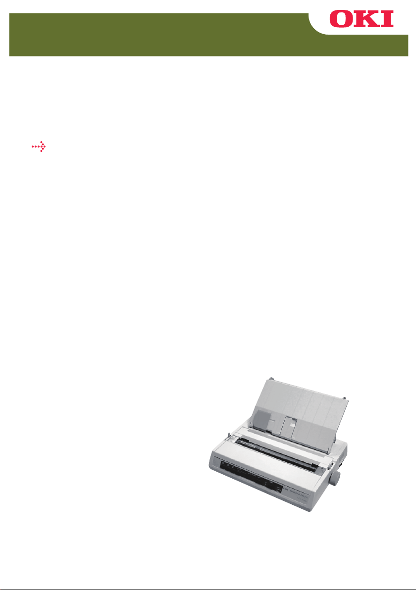
The ML280eco is an entry level 9 pin dot-matrix printer. It is fast,
robust, compact and light. Outstanding reliability, compact size and
ease of use make it ideal for industrial workstation applications, as
well as customer service points in wholesale, retail and service
environments.
USING THIS MANUAL
This manual will lead you logically through the unpacking, setting
up and operation of your printer to help you to make the best use
of its many advanced features. Also included are guidelines for
troubleshooting and maintenance to ensure that it continues to
perform at its best. Instructions are also provided for adding
optional accessories as your needs evolve.
The User's Guide has been written using one printer as a
model, and the illustrations/screenshots reflect this. What
you see will be appropriate to the model you are installing.
The User's Guide has been designed to provide you with a
clear presentation on the installation and maintenance of
your new printer. This information is compiled in the logical
sequence required to result in a successful installation.
NOTE
The information in this manual is supplemented by the extensive
online help facility associated with the printer driver software.
In addition, we provide a Technical Reference Guide for those
users requiring more in-depth Technical information. This is
available in English only.
INTRODUCTION > 6
Page 7
ONLINE USAGE
This manual is intended to be read on screen using Adobe Acrobat
Reader. Use the navigation and viewing tools provided in Acrobat.
You can access specific information in two ways:
In the list of bookmarks down the left hand side of your
screen, click on the topic of interest to jump to the required
topic. (If the bookmarks are not available, use the Table of
Contents).
In the list of bookmarks click on Index to jump to the Index.
(If the bookmarks are not available, use the Table of
Contents). Find the term of interest in the alphabetically
arranged index and click on the associated page number to
jump to the page containing the subject.
PRINTING PAGES
The whole book, individual pages, or sections may be printed. The
procedure is:
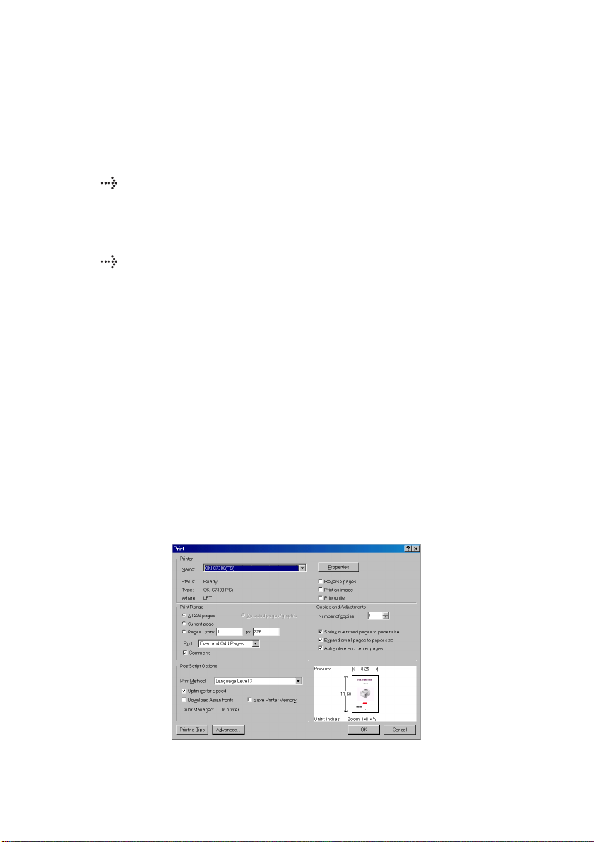
1. From the toolbar, select [File], then [Print] (or press the
Ctrl + P keys).
2. Choose which pages you wish to print:
(a) All pages, for the entire manual.
(b) Current page for the page at which you are looking.
INTRODUCTION > 7
Page 8

(c) Pages from and to for the range of pages you specify
by entering their page numbers.
3. Click on OK.
INTRODUCTION > 8
Page 9
GETTING STARTED
1
2
4
3
5
6
7
8
9
LOCATION
Select a firm, solid surface on which to site your printer.
Allow enough space around the printer to easily access the
platen knob and the various paper feed paths.
Make sure a suitable grounded power outlet is available
nearby.
Read the Installation Safety Booklet.
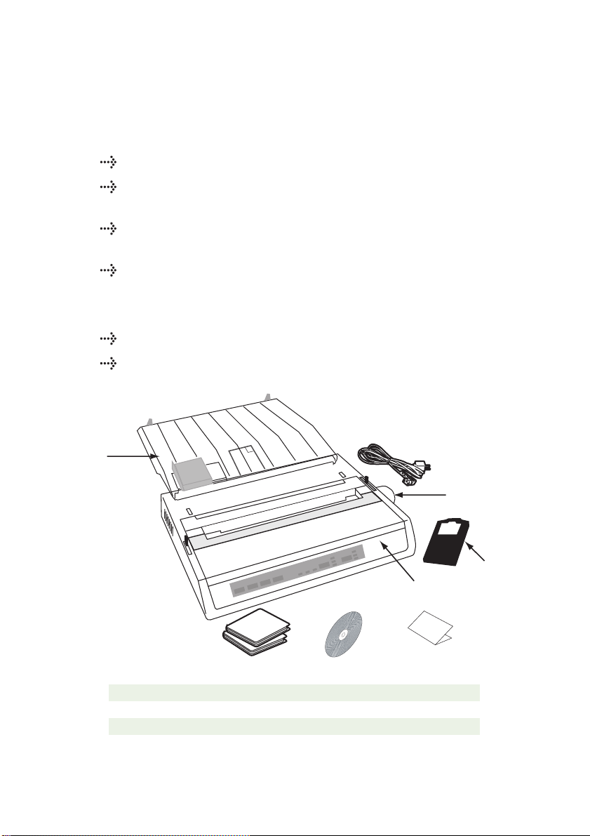
CONTENTS AND UNPACKING
If any items are missing, contact your dealer immediately.
Keep your packing materials and carton in case you ever
need to ship or transport the printer.
1. Printer 6. Installation Safety booklet
2. Ribbon Cartridge 7. Pan European limited Warranty
3. Power Cord(s) - AC 8. Printer Software CD
4. Platen Knob 9. Setup Guide
5. Sheet Separator
GETTING STARTED > 9
Page 10
Do not plug the printer into the AC supply until the following
2
1
steps have been completed:
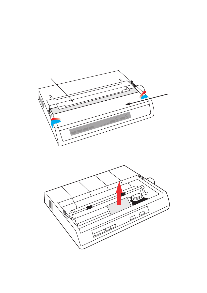
REMOVING THE SHIPPING RESTRAINT
1. Remove any packing tape. Insert your hand in the top cover
slot (2) and remove the access cover (1) by lifting it.
2. Remove the printhead shipping restraint. Keep shipping
restraint for future use.
3. Reinstall the access cover.
GETTING STARTED > 10
Page 11
INSTALLING/REPLACING THE RIBBON CARTRIDGE
CAUTION!
When replacing a Ribbon Cartridge, make sure you have the
correct replacement ribbon for your printer. The wrong ribbon
will not print when installed in your printer.
RIBBON CARTRIDGE HANDLING
Leave unused ribbon cartridges in their packages until
needed.
Careful; the ribbon ink may cause permanent stains.
Ribbon ink on skin or clothing can usually be removed with
soap and water.
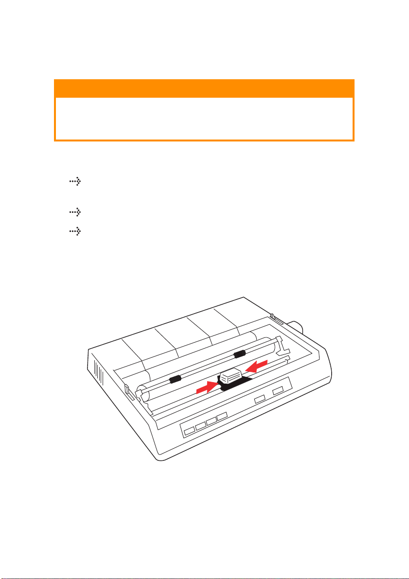
Make sure the printer is turned OFF.
1. Open the access cover and center the printhead (1).
GETTING STARTED > 11
Page 12
2.
When replacing a Ribbon Cartridge, first remove the old one
WARNING!
If you are replacing the ribbon Cartridge, the printhead may be
HOT!
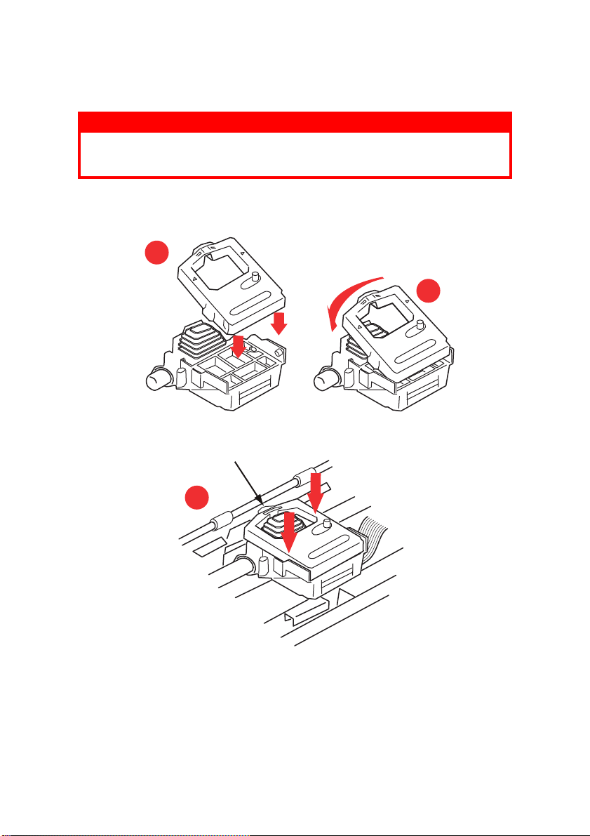
3. Unpack the ribbon cartridge and install it on the printhead.
1
2
X
.
3
GETTING STARTED > 12
Page 13
4. Press gently on the ribbon cartridge until you feel it click into
a
place.
CAUTION!
Do not remove the ribbon shield ("X" in graphic above) from
the ribbon!
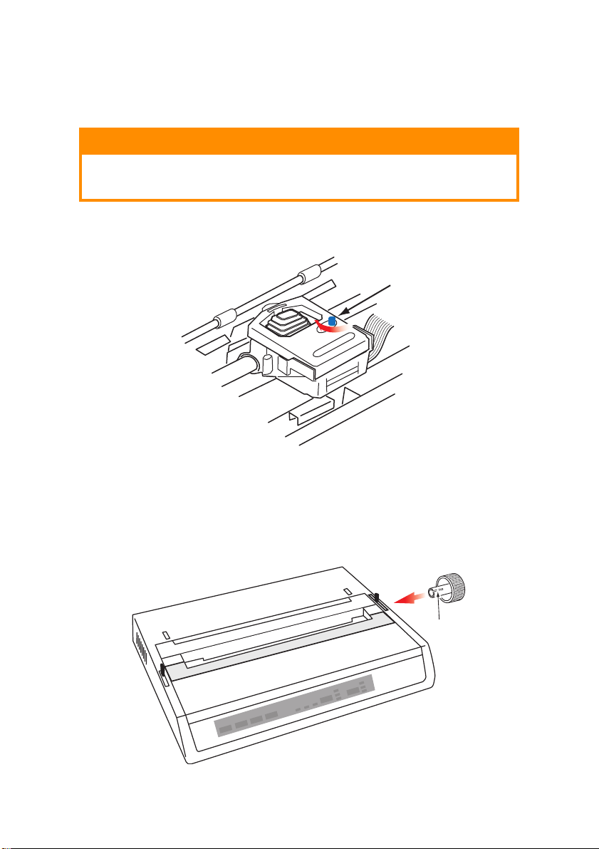
5. Turn the take-up knob (a) in the direction of the moulded
arrow to take up any ribbon slack.
a
6. Replace the access cover.
INSTALLING THE PLATEN KNOB
If the Platen Knob is not already fitted, align the key way (a)
correctly and push it firmly into place.
GETTING STARTED > 13
Page 14
ADJUSTING THE HEAD GAP
The head gap is the distance between the print head and the platen
roller. When you use envelopes or multi-part forms you will need to
have a larger gap than when using plain paper. Use the
recommended head gap to ensure the best print quality and easy
paper feed.
CAUTION!
Incorrect setting of the print head gap can cause print head
damage or ribbon jams. To avoid these problems set the print
head gap for the type of stationery being used.
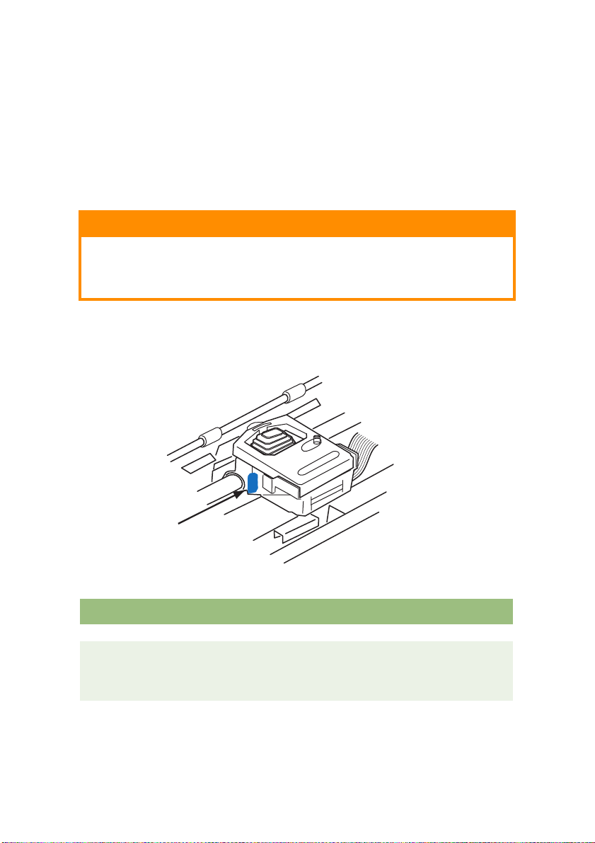
To adjust the print head gap, move the coloured lever located to the
left of the ribbon cartridge (a), to the correct position for the type of
stationery being used......
a
.....as detailed in the following table:
PAPER TYPE WEIGHT LEVER POSITION
Single part paper 14 - 20lb (52 - 75gm) 1, 2
Form
Two pa rt
Three part
Four part
9 - 11 lb. (35 - 40 gm) with a
maximum thickness of
0.28mm
GETTING STARTED > 14
2 - 3
3
3
Page 15

FITTING THE PAPER SEPARATOR
The Paper Separator is utilised when using single sheets (no
carbons) and when using continuous stationery to separate the
ingoing/outgoing paper to prevent paper jams. It is fitted as follows:
1. Grasp the paper separator by either side, with the spring
loaded stays to the rear of the printer.
2. Locate the two hooked lugs on the edges of the paper
separator into the two corresponding slots in the top of the
printer.
3. Release paper separator on to the top of the printer.
GETTING STARTED > 15
Page 16
SETTING UP YOUR PRINTER
POWER CONNECTION
WARNING!
Operations of this equipment are not warranted when the
equipment is connected to UPS (Uninterruptible Power Supply)
and/or inverter. Doing so may result in damage of this
equipment. Do not use an UPS and/or inverter.
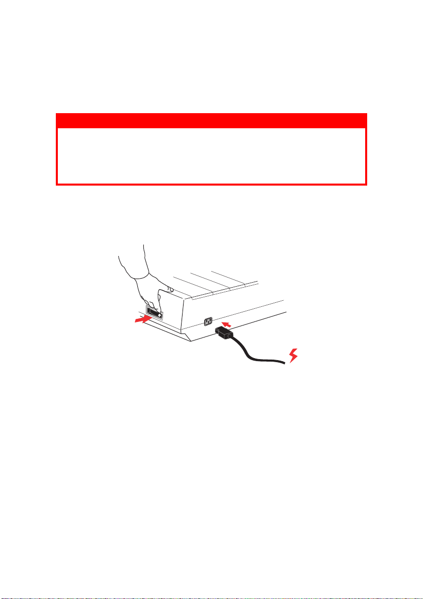
Make sure both the printer and the computer are switched OFF.
1. Plug the power cord into the back of the printer, then into a
grounded AC outlet.
2. Switch the Printer ON.
SETTING UP YOUR PRINTER > 16
Page 17

LOADING PAPER
Three types of paper can be used with your printer:
Single sheet (with or without the optional cut sheet feeder)
Roll paper (use the correct rollpaper stand)
Fan-fold paper (with or without the optional tractor feed unit)
When using fan-fold paper, adjust the distance between the
sprocket pins at the ends of the platen to the holes in the paper.
Fan-fold paper can be fed from the rear of the printer, or, if a slotted
stand is available, from underneath.
REAR FEED CONTINUOUS FORM FAN-FOLD PAPER
Ensure that the printer is switched OFF and the power supply lead
removed.
1. Place a box of fan-fold paper behind the printer.
2. Remove the Access cover (1).
3
2
1
SETTING UP YOUR PRINTER > 17
Page 18

3. Move the Bail arm lever (2) (on the left-hand side of the
4
5
2
3
printer) to the front of the machine to lift the Bail bar.
4. Move the Paper lever (3) (on the right-hand side of the
printer) to the front of the machine, to the fan-fold symbol.
5. Insert the first sheet of paper between the separator paper
guides (4).
Push the paper in just enough so that its sprocket holes
engage the sprocket pins located on the platen ends.
6. Turn the Platen knob (5) to advance the paper until it
appears in front of the platen.
7. Move the Bail arm lever (2) to the rear of the machine to
lower the Bail bar.
8. Use the Platen knob (5) to advance the paper to the first
printing line.
9. Replace the Access cover and switch the printer ON.
SETTING UP YOUR PRINTER > 18
Page 19

BOTTOM FEED CONTINUOUS FORM FAN-FOLD PAPER
Ensure that the printer is switched OFF and the power supply lead
removed.
1. Place the printer on a slotted printer stand, carefully aligning
the slot in the stand with the slot in the base of the printer.
2. Place a box of fan-fold paper under the printer stand.
3. Remove the Access cover.
4. Move the Bail arm lever (2) (on the left-hand side of the
printer) to the front of the machine to lift the Bail bar.
5. Move the Paper lever (3) (on the right-hand side of the
printer) to the front of the machine, to the fan-fold symbol.
6. Insert the first sheet of paper through the opening in the
printer stand and the bottom of the printer.
7. Adjust the Platen sprocket(s) to align with the sprocket
holes in the paper.
8. Use the Platen knob to gently pull the paper up until it
appears in front of the platen, and above the Bail bar.
9. Move the Bail arm lever to the rear of the machine to lower
the Bail bar (6).
10. Use the Platen knob (5) to advance the paper to the first
printing line.
11. Replace the Access cover and switch the printer ON.
SETTING UP YOUR PRINTER > 19
Page 20

TOP FEED SINGLE SHEET PAPER
1
2
3
Your printer can accommodate single sheets of 216mm width x 297
or 355mm length paper. Remove the Tractor Feed unit and any
other accessories, then raise the Paper Separator into its upright
position.
1. Switch the printer ON.
2. Move the Paper lever (1) (on the right-hand side of the
printer) to the rear of the machine, to the Blank sheet of
paper symbol.
3. Ensure that the printer is OFF-LINE (press the SELECT
switch if necessary).
Make sure the Bail arm lever (2) is set to the rear of the
machine (in its closed position).
4. Raise the paper separator as shown above.
SETTING UP YOUR PRINTER > 20
Page 21

5. Adjust the Cut Sheet guide (3) on the Paper Separator to
position the left edge of the sheet.
NOTE
If letter size paper is used, set the cut sheet guide to the line mark on
the paper separator. 80 character width text (10cpi) is then positioned
centrally on the paper.
6. Insert a single sheet along the Cut Sheet guide until it
reaches the pinch roller. Be sure to keep the paper inside
the platen ends, otherwise the built-in sprocket rollers will
tear it.
7. Move the Bail arm lever (2) towards the front of the
machine, into the open position. The sheet of paper will be
pulled around the platen.
8. Close the Bail arm lever (2) ensuring that the paper has
been positioned correctly.
9. Press the SELECT button to bring the printer ON-LINE.
10. The sprockets can be released and moved out from the
platen if required.
TESTING YOUR PRINTER
Your printer has a built-in test (self test) to make sure that your
printer is set up and working correctly.
1. Firstly, load continuous forms paper into the printer (Please
see the "Loading Paper" section of this Guide).
2. Hold down the LINE FEED button and turn the printer ON.
The printer will begin its test print.
3. To stop the test, press the SELECT button or turn the printer
OFF.
SETTING UP YOUR PRINTER > 21
Page 22

Typical test print:
ML280eco MEI E F/W XX.XX 46614301YR-XX
HSD 10CPI
!"£$%^&*()0123456789:;<=>@aABCDEFGHIJKLMNOPQRSTUVWXYZ[\]abcdefghijklm
nopqrstuvwxyz
NOTE
The top of each print test contains information about your printer
model. Be sure to have a copy of the printout handy if you have to call
for service.
LD XX.XX
SETTING UP YOUR PRINTER > 22
Page 23
COMPUTER CONNECTIONS
NOTE
The operation of a printer is not assured if a USB compatible
device is connected concurrently with other USB compatible
machines.
Interface cables are not supplied with your printer.
PARALLEL (LPT) CONNECTION, IEEE 1284
Requires a bi-directional cable, max. length 6 ft. (1.8 m),
not supplied
The printer has a 36-pin Centronics type socket.
CAUTION!
Make sure the printer and computer are both turned OFF.
1. Switch both the computer and the printer OFF.
2. Attach a suitable bi-directional cable to the parallel
connector on the back of the printer. Then attach and
secure the cable to your computer.
3. Turn the printer and computer back ON.
SETTING UP YOUR PRINTER > 23
Page 24

USB CONNECTION
Requires a USB 1.1 or higher cable, maximum length 19.7 ft.
(5 m), not supplied.
Printer has a USB series "B" receptacle.
NOTES
The operation of a printer is not assured if a USB compatible
device is connected concurrently with other USB-compatible
machines.
When connecting multiple printers of the same type, they appear
as *****, ***** (2), ***** (3), etc. These numbers depend on the
order of connecting or turning on each printer.
USB is a "hot-pluggable" protocol. This means that the printer and
computer do not necessarily have to be switched OFF.
1. Attach a suitable USB cable to the printer. Then attach the
cable to your computer.
2. If you have turned the computer and printer OFF, turn them
back ON.
Follow any on-screen insructions.
SETTING UP YOUR PRINTER > 24
Page 25

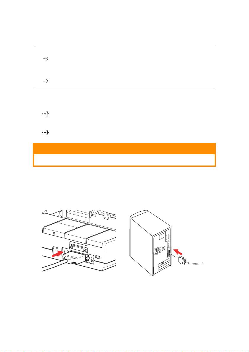
SERIAL CONNECTION
1
The serial interface settings will appear in the printer menu and
may need to be adjusted to match your PC.
CAUTION!
Make sure the printer and computer are both turned OFF.
1. Switch both the computer and the printer OFF.
2. Plug the cable into the serial ports of both your PC and
printer and tighten the thumbscrews (1).
The cable should comply with the RS232C Serial Interface
Specification and have a maximum length of 15 metres (49ft).
3. Turn the printer and computer back ON.
SETTING UP YOUR PRINTER > 25
Page 26

PRINTER DRIVERS
Printer drivers enable your computer to communicate with the
printer. As with most printer manufacturers, Oki creates printer
drivers for use with popular types of software, such as Microsoft
Windows operating systems, from Windows Server 2008/Windows
7 onwards. Installing a printer driver is normally a simple process
of making a selection within the software. If a driver is not available
by name for your printer, contact the software manufacturer and
ask if they can supply an updated version of their software with
additional drivers. Alternatively, check the driver availability on the
OKI Data global Web Site at:
http://www.oki.com/printing/
If you are using bespoke software or software created specifically
for your company, it is unlikely that the CDs supplied with this
software will include drivers for your printer. In this instance you will
have to choose a driver as closely compatible as possible.
Compatible drivers contain printing codes that will operate your
printer. They may not offer the special features of an original driver,
but they will allow you to perform normal printing tasks.
Oki's printers contain more than one printer emulation selectable
via the menu system. See the table below for compatible drivers.
However, please note that the emulations listed toward the bottom
of this list are more basic and offer fewer of the printer's features.
MICROLINE
MULATION
E
ML280 Microline ML280 IBM ML280 Epson
IBM EMULATION EPSON LQ EMULATION
IBM Graphics Printer Epson FX80
Epson FX
SETTING UP YOUR PRINTER > 26
Page 27

OPERATING YOUR PRINTER
LINE
FEED
FORM
FEED
TOF
SET
10
12
17
SELECT
ALARM POWER PITCH
MODE
HSD
NLQ
UTILITY
FRONT PANEL OPERATION
The Front Panel has 9 indicators and 6 buttons. The function of
each is as follows:
Indicators
SELECT Lit - Printer ON-LINE, unlit printer OFF-LINE. Flashes with ALARM
ALARM
POWER
PITCH Indicates the current character pitch selected.
MODE Indicates the current print mode selected - NLQ, Utility, HSD (HSD is
on to indicate a fault has been detected.
If lit permanently and SELECT is not lit - it is indicating paper
out or paper jam if a Cut Sheet Feeder is in use.
If lit permanently and SELECT is flashing - it is indicating
that auto diagnostics have detected an error.
If flashing and SELECT is lit - it is indicating either printhead
temperature protection circuit, firmware protection of line feed
or space motor is operating. In any case, normal print
operation will resume after a cooling period.
Indicates that the printer is connected to the supply and is switched ON.
SSD if 12cpi is selected).
Buttons
LINE
FEED
FORM
FEED
TOF SET Sets new top of form (TOF) position.
SELECT Places printer ON or OFF line.
PITCH Changes the character pitch setting (cpi).
MODE Changes the print style setting.
Advances the paper one line for each press.
Advances the paper to the next top of form (TOF) or ejects any single
sheet paper from the printer.
OPERATING YOUR PRINTER > 27
Page 28

Additional button functions if pressed at Power ON
LINE FEED Initiates the printer self test.
SELECT
and LINE
FEED
SELECT
and FORM
FEED
SELECT Enters the printer's Menu Mode.
TOF SET Selects the print pitch as 17cpi.
Initiates the printer's continuous rolling ASCII test.
Places the printer into a Hex dump mode, printing all data and
control commands received as HEX codes for fault finding.
OPERATING YOUR PRINTER > 28
Page 29

SETTING PRINTER DEFAULTS
The printer has an internal MENU containing a number of default
conditions that can be set to enable your printer to match the
parameters required by your computer.
ENTERING THE MENU MODE
1. Power on the printer while holding down the SELECT
button. The 12 and UTILITY LEDs will flash.
2. Press the SELECT button to print the complete menu. This
will detail the current default settings.
3. Press the LINE FEED button to select the relevant group
that needs to be changed (the group is the left-hand column
on the MENU printout).
4. Press the FORM FEED button to select the relevant item
within the selected group (the Item is the centre column on
the MENU printout).
5. Press the TOF SET button to cycle through the settings
available for the item you want to change (the settings are
the right-hand column on the MENU printout).
6. Once you have reached the setting that you want, press
either the LINE FEED button (for the next group) or the
FORM FEED button (for the next item) to be changed.
Follow steps to 3 to 5 until all your required settings have
been changed.
7. On completion of the changes, press the PITCH and MODE
buttons together to exit and save all the changes you have
made.
NOTE
Important, do not exit the menu mode by switching off the printer, as
this will not save any changes you have made.
OPERATING YOUR PRINTER > 29
Page 30

DEFAULT MENU SELECTIONS
GROUP ITEM SETTING
Printer
Control
Font Print Mode
Symbol Sets Character Set
Vertical
Control
Set-up Graphics
Parallel I/F I - Prime
Serial I/F
Only appears
for printers
equipped with
Serial
Interface.
Emulation Mode
Draft Mode
Pitch
Proportional Spacing
Style
Size
Language Set
Zero Character
Code Page
Slashed Letter O
Line Spacing
Skip Over Perforation
Page Length
Receive Buffer Size
Paper Out Override
Print Registration
Operator Panel Function
Reset Inhibit
Printer Suppress Effective
Auto LF
Auto CR
SI Select Pitch (10 CPI)
SI Select Pitch (12 CPI)
Time Out Print
Auto Select
ESC/SI Pitch
Impact Mode
Power Saving
Power Save Time
Bi - Direction
Parity
Serial Data 7/8 Bits
Protocol
Diagnostic Test
Busy Line
Baud Rate
DSR Signal
DTR Signal
Busy Time
IBM
Utility
SSD
10 CPI
No
Normal
Single
Set II
ASCII
Unslashed
USA
No
6 LPI
No
12"
Uni-directional
64K
No
0
Semi Operation
No
Ye s
No
Ye s
17.1 CPI
20 CPI
Invalid
No
17.1 CPI
Normal
Enable
5 min
Buffer Print
Enable
None
8 Bits
Ready/Busy
No
SSD9600 BPS
Val id
Ready on Power UP
200 ms
OPERATING YOUR PRINTER > 30
Page 31

USING THE PULL TRACTOR UNIT (IF FITTED)
A
B
A
B
Paper can be loaded either from the rear of the printer or from the
bottom if you have a slotted printer stand.
1. Remove the access cover.
2. Adjust the left tractor if necessary, making sure that it is not
more than 12.7mm (0.5 inch) from the left-hand end of the
tractor unit. To move the tractor, pull the lock lever forward,
slide the tractor to the desired position, then push the lock
lever backward to lock it in place.
3. Adjust the right tractor to the paper width by pulling its lock
lever forward, sliding the tractor to the desired position, then
pushing the lock lever backward to lock it in place.
OPERATING YOUR PRINTER > 31
Page 32

4. Pull the paper under the Bail bar and up to the level of the
A
B
tractor unit.
5. Open the sprocket covers and slide the paper release lever
forward.
6. Locate the sprocket holes in the paper over the sprockets
on the tractor unit and close both sprocket covers (leave the
paper release lever open).
7. Replace the access cover.
OPERATING YOUR PRINTER > 32
Page 33

USING THE ROLL PAPER STAND (IF FITTED)
LOADING THE PAPER
1. Open the paper separator all the way.
2. Remove the paper roller.
Note that there is a disk on the left end of the roller.
3. Slide the roller into a tube of paper.
Ensure the disk is on the left side and paper must roll up from
the bottom.
4. Replace the paper roller back into the stand, with the disc
on the left side.
5. Feed the paper over the roller on the stand. NOT UNDER!
6. Adjust the round paper guides at either side to the paper
width.
7. Feed the paper down behind the platen and use platen
knob to bring paper through the printer.
Lift the bail arm as paper comes round to front of platen. (The
paper release lever needs to be in the top position to perform
this step).
OPERATING YOUR PRINTER > 33
Page 34

8. Continue to feed the paper through for approx. 4 inches.
a
b
c
d
9. Move the paper release lever toward the front of the
machine. Align the paper so that the exit and entry paper
edges align. Return the paper release lever to the rear
position to re-apply pressure on platen.
10. Close the bail arm.
11. Replace the access cover. Fit the cover tabs into the slots at
the printer front. Lower the cover carefully, making sure the
paper fits through the front slot in the access cover.
12. Lower the paper separator so that paper enters the printer
from under the separator and exits the printer going over the
separator (see below).
13. Turn the platen knob to move the paper to the point where
you want printing to start. (Many word processing packages
automatically allow for a top margin of 25.4mm (1 inch)).
Correct paper path
a Paper roll b Roll Paper Stand
c Platen d Paper Guide
OPERATING YOUR PRINTER > 34
Page 35

MAINTENANCE
REPLACING THE RIBBON CARTRIDGE
See "Installing/Replacing the Ribbon Cartridge" on page 11.
ADJUSTING THE PRINTHEAD GAP
See "Adjusting the Head Gap" on page 14.
LOADING PAPER
See "Loading Paper" on page 17.
TESTING YOUR PRINTER
See "Testing your printer" on page 21.
MAINTENANCE > 35
Page 36

TROUBLESHOOTING
GENERAL INFORMATION
Here are some general things to check before proceeding with
detailed troubleshooting.
> Is the printer plugged in and turned ON?
> Are the connections (power and interface) secure?
> Is the product being operated under the proper ambient
conditions?
> Does the paper being used meet the specifications for this
product?
> Is the paper properly installed?
> Is the ribbon properly installed?
> Is an Oki ribbon being used?
> Is the printhead gap correctly set?
> Are the correct printer drivers being used for the printer?
NOTE
Settings in your software application will normally override any
settings in your printer driver.
Printer driver settings normally override settings from the printer
menu or printer front panel.
Problem
My word processor files do not print the way I have the menu and
front panel set.
Solution
Remember: The note above!
Before sending a file to the printer, many word processors send
either an "initialization string" or an I-Prime signal to the printer.
TROUBLESHOOTING > 36
Page 37

The initialization string contains codes that override the panel and
menu settings. To change your printer to ignore the reset code,
enter the Menu Mode, go to the Set-Up group and change the
setting for Reset Inhibit to Yes.
The I-Prime signal will automatically override any front panel
settings you have made. To eliminate this problem, enter the Menu
Mode, go to the Parallel Interface group and change the setting
for I-Prime to Invalid.
For more information on changing menu settings, see "Changing
the Menu Settings" in Chapter 3.
Problem
Nothing happens when I turn ON the printer.
Solution
Check the power cord connection to the outlet and to the printer. If
you are using a power strip, make sure it is turned ON, and that the
fuse hasn't blown or that the circuit breaker hasn't tripped. If the
solution is not obvious — call for service.
Problem
The printer does not print when the computer sends data.
Solutions
1. Is the SEL light on? If not, press the SEL key.
2. Check that the interface cable is securely connected to both
the printer and the computer.
Problem
I'm getting strange symbols, incorrect fonts, etc., when I try to print
a document.
Solutions
1. Check to be sure that the printer driver you have selected in
your software matches the printer emulation.
2. Please refer to the Printer Driver section for details of
emulations, then check the menu settings (see "Setting
Printer Defaults" in the Operating your Printer section).
TROUBLESHOOTING > 37
Page 38
3. If you have embedded any printer commands in your
1
software, check to be sure that you entered them correctly.
Problem
Ink smears on the paper when I print narrow columns.
Solutions
The head gap could be too close. Check that the head gap is set
correctly (see the table in "Adjusting the head gap" in the Getting
Started section).
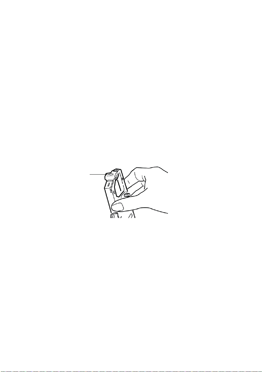
Problem
I've installed a new ribbon and the printing is smeared and
streaked.
Solution
The ribbon shield (1) is either loose or missing.
Remove the ribbon cartridge and check the ribbon shield.
If it is loose, secure it. If it is missing, find it and install it. If
you cannot find it, replace the ribbon cartridge.
Tip: If you still have an old ribbon cartridge, remove the
shield from it and install it on the ribbon cartridge on your
printer.
Problem
There are dots missing in my printouts (typically, tops and /or
bottom of characters missing).
TROUBLESHOOTING > 38
Page 39

Solution
The head gap may not be set correctly. Try moving the headgap
lever to a lower setting. If that doesn't help, the printhead may be
damaged; call for service.
Problem
The ALARM light is flashing.
Solution
Try turning the printer OFF and then back ON again. If the light still
blinks, call for service.
Problem
The Print Quality and Character Pitch keys on the front panel don't
work.
Solution
The Operator Panel Function in the printer menu can be used to
disable these buttons (Limited Function). If the printer is part of a
customized system or if it is used by a number of people, the
system manager may have used this option to make sure the
printer is always set properly.
Check with your system manager before changing any menu
settings.
Problem
My printer keeps indicating "Paper out" when there is paper
installed.
Solution
The most likely cause is that the paper sensor groove in the platen
is not being covered by paper. Re-align paper to cover the sensor
groove.
Problem
When I am using continuous feed paper, the sprocket holes are
torn, causing alignment problems.
Solution
The most likely cause is that the paper lever is set to friction feed.
Move the lever to "Fan-fold" (to the front of the printer).
TROUBLESHOOTING > 39
Page 40

CLEARING PAPER JAMS
REAR FEED JAMS
1. Turn the printer OFF.
2. Use the platen knob to back the paper all the way out of the
printer.
CAUTION!
Make sure the printer is turned OFF before you open the
access cover.
WARNING!
The printhead may be HOT!
3. Open the access cover, move the bail arm lever toward
the front of the printer and remove any torn paper.
4. Reload the paper (see section on "Maintenance"), move the
bail arm lever towards the rear of the printer and close the
access cover.
5. Turn the printer ON.
TROUBLESHOOTING > 40
Page 41

REAR FEED, REPEATING PAPER JAMS
If the paper keeps jamming, you may have:
> defective paper
> misaligned paper
> bits of paper in the paper path
Defective Paper
Replace the defective paper with a fresh stack.
Misaligned Paper
1. Turn the printer OFF.
2. Use the platen knob to back the paper all the way out of the
printer.
3. Tear off a couple of sheets of paper, leaving a new, clean,
square-cut edge.
4. Reload the paper and turn the printer back ON.
Bits of paper in the paper path
Depending on which paper feed method you are using, remove any
accessories, open the access cover and remove any debris from
the paper path.
WARNING!
Always ensure that the printer is switched OFF and that
the power supply lead is disconnected.
If the printer has been recently used, the printhead may
be HOT!
TROUBLESHOOTING > 41
Page 42

SINGLE SHEET PAPER JAMS
1. Turn off the printer.
2. Use the platen knob to back the paper out.
3. Open the access cover.
4. Remove any torn pieces from around the carriage.
5. Close the access cover.
TROUBLESHOOTING > 42
Page 43

PARTS AND ACCESSORIES
PURCHASING PARTS & ACCESSORIES
Before you purchase parts and accessories, make a note of your
printer model name (see the front of the unit) and have the correct
part number and description of the item you wish to purchase. Item
descriptions and part numbers are provided in this section.
Consult the dealer where you purchased your printer.
Locate an Authorised Oki Data Reseller by visiting your
local Oki web site. Links to all countries are provided on:
http://www.oki.com/printing/
x 2
5
7
3
1
6
4
2
ITEM PART NUMBER COMMENT
Ribbon Cartridge (1) 09002303 Life - 3 million characters
Platen Knob (2) 40673402
Power Cord AC (3) - Euro YS4011-1272P001
UK YS4011-1273P001
Software CD (7) 44500105 (for Europe)
Printhead (4) 42666401 Life - 200 million characters
Access Cover (5) 42594601
Sheet Guide (6) 42017901
44781607 (for Oceania)
PARTS AND ACCESSORIES > 43
Page 44

OPTIONS
1
2
OPTION PART NUMBER
Pull Tractor Assembly (1) 09002363
Roll Paper Stand (2) 40108610
All Accessories are supplied complete with an Installation Guide.
PARTS AND ACCESSORIES > 44
Page 45

SPECIFICATIONS
ITEM SPECIFICATION
Print Method
Printhead
Emulations (co-resident)
Print Speed
High Speed Draft (HSD)
Utility (UTL)
Near Letter Quality (NLQ)
Paper Specifications
Type Feed Weight Width (range)
Cut Sheets Top only 16 to 21lb. (60 to 81g/m²)
Single part Continuous Rear/Bottom 14 to 20lb. (53 to 75g/m²) 3 to 9.5 inches
Multi Part Continuous Rear/Bottom 14 to 20lb. (53 to 75g/m²) 3 to 9.5 inches
Maximum thickness 0.28mm (0.11 inches)
Maximum number of
sheets
Reliability
Ribbon Life (black)
Printhead Life
Mean Time Between
Failures (MTBF)
Mean Time to Repair
(MTTR)
3 million characters, on average
200 million characters average in 10cpi utility mode
20,000 hours at 25% duty cycle and 35% page density
15 minutes
General Printer Characteristics
Dimensions Height: 80mm (height) x 360mm (width) x 275mm (depth)
Weight 3.9Kg
Buffer size 128Kb
Noise level 58dBA (Utility-MODE)
Power requirements 220-240VAC (±10%) @50/60Hz (±2%)
Impact dot matrix
9 pins, 0.34 mm (0.0134") diameter, with
thermal protection
Epson FX
IBM Graphics
Oki MICROLINE
333cps*
250cps*
62.5cps*
* cps = characters per second
4 (original plus 3 copies) carbonless
SPECIFICATIONS > 45
Page 46

ITEM SPECIFICATION
Temperature
Operating
Storage
Humidity
Operating
Storage
Interfaces:
Standard: Centronics parallel, IEEE-1284 compliant
5 to 35°C
-40 to +70°C
20 to 80% RH
5 to 95% RH
USB 2.0 (Full Speed)
RS-232C Serial
SPECIFICATIONS > 46
Page 47

INDEX
A
Access cover .......................17, 19
Additional button functions if
pressed at Power ON ................28
ALARM ......................................27
Auto CR .....................................30
Auto LF ......................................30
Auto Select ................................30
B
Bail arm lever.......................18, 19
Baud Rate..................................30
Bi - Direction ..............................30
Blank sheet of paper symbol .....20
Bottom feed continuous form fan-
fold paper...................................19
Busy Line ...................................30
Busy Time..................................30
C
Centering printhead position...... 38
Character Set.............................30
Clearing Paper Jams .................40
Code Page.................................30
Computer Connections..............23
D
Diagnostic Test..........................30
DSR Signal ................................30
DTR Signal ................................30
E
Emulation Mode.........................30
ESC/Sl Pitch ..............................30
F
Fanfold.................................18, 19
Fitting the Paper Separator........15
Fonts
Embedded Printer
Commands............................38
FORM FEED..............................27
Front Panel ................................27
G
Graphics ....................................30
H
Humidity.....................................46
I
Impact Mode ..............................30
Initialization string ......................36
Installing the Ribbon
Cartridge ....................................11
I-Prime .................................30, 36
L
Language Set ............................30
Limited Operation ......................39
LINE FEED ..........................27, 28
Line Spacing ..............................30
Loading Paper ...........................17
M
Mean Time Between Failures
(MTBF).......................................45
Mean Time to Repair (MTTR)....45
MODE ........................................27
O
Operator Panel ..........................30
Operator Panel Function............39
P
Page Length ..............................30
Paper lever ....................18, 19, 20
Paper out Override ....................30
Paper Separator ..................20, 21
Paper Specifications..................45
Parallel (LPT) Connection..........23
Parallel Interface
I-PRIME Signal.......................36
Parity..........................................30
INDEX > 47
Page 48

PITCH ........................................27
POWER .....................................27
Power Connection ...............16, 23
Power Save Time ......................30
Power Saving.............................30
Print Method ..............................45
Print Registration .......................30
Print Speed................................45
Printer Drivers............................30
Printer Suppress Effective .........30
Printhead ...................................45
Protocol......................................30
R
Rear feed continuous form fan-fold
paper..........................................17
Receive Buffer Size ...................30
Removing the shipping
restraint......................................10
Reset Inhibit...............................30
Ribbon Shield ......................13, 38
RS-232C Serial Interface...........46
SELECT and FORM FEED........28
SELECT and LINE FEED ..........28
Serial Cable Connection............25
Serial Data 7/8 Bits....................30
Setting Printer Defaults..............29
SI Select Pitch (12 CPI).............30
Skip Over Perforation ................30
Software
Embedded commands ...........38
Software vs. printer settings ...36
T
Time Out Print............................30
TOF SET..............................27, 28
Top feed single sheet paper ......20
Tractor Feed unit .......................20
U
Unpacking....................................9
USB Connection ........................24
Using the pull Tractor Unit .........31
Using the Roll Paper Stand .......33
S
Sl Select Pitch (10 CPI) ............. 30
SELECT.....................................27
Z
Zero Character...........................30
INDEX > 48
Page 49

OKI CONTACT DETAILS
OKI Systems (UK) Ltd.
Blays House
Wick Road
Egham
Surrey
TW20 0HJ
Tel: +44 (0) 1784 274300
Website: www.oki.com/uk
OKI Systems (Ireland) Ltd
A7 Calmount Park
Ballymount
Dublin 12
D12 TX94
Ireland
Tel: +353 (0) 1 4049590
Fax: +353 (0)1 4049591
Website: www.oki.com/ie
OKI Systems (Czech and Slovak), s.r.o.
Futurama Business Park Sokolovská 651/136D
186 00 Praha 8
Czech Republic
Tel: +420 224 890158
Fax: +420 22 232 6621
Website: www.oki.cz, www.oki.sk
Oki Systems (Deutschland) GmbH
Hansaallee 187
40549 Düsseldorf
Tel: +49 (0) 211 / 5266-0
Fax: +49 (0) 211 59 33 45
Website: www.oki.de
Email: info@oki.de
CEE Export Group:
OKI Systems (Poland) Sp. z o.o.
Platinum Business Park 2, 3rd Floor
ul. Domaniewska 42, 02-672 Warsaw
Poland
Tel: +48 (0) 22 448 65 00
Fax: +48 (0) 22 448 65 0
Website: www.oki.pl
Albania, Bosnia, Bulgaria, Croatia,
Cyprus, Estonia, Greece, Israel,
Latvia, Lithuania, Macedonia,
Romania, Serbia, Slovenia
Oki Systèmes (France) S.A.
Zone Silic - Immeuble Osaka
21 rue du Jura
CS 90277
94633 RUNGIS Cedex
Paris
Tél: Standard 0820 200 410
(0.09€/min depuis une ligne fixe*)
Hotline 01 76 54 21 50 (n° non surtaxé)
Website: www.oki.fr
OKI Systems (Magyarország) Kft.
H-1133 Budapest,
Váci út 76
Hungary
Telefon: +36 1 814 8000
Telefax: +36 1 814 8009
Website: www.okihu.hu
OKI Systems (Italia) S.p.A.
via Milano, 11,
20084 Lacchiarella (MI)
Tel: +39 (0) 2 900261
Fax: +39 (0) 2 70059826
Website: www.oki.it
OKI Systems (Polska) Sp. z o.o
Platinium Business Park II, 3rd Floor
ul. Domaniewska 42
02-672 Warsaw
Poland
Tel: +48 22 448 65 00
Fax: +48 22 448 65 01
Website: www.oki.pl
E-mail: oki@oki.com.pl
Hotline: 0800 120066
E-mail: tech@oki.com.pl
OKI Europe Limited, Sucursal em Portugal
Av. Quinta Grande, nº 53
7º D - Alfragide
2610-156 Amadora
Portugal
Tel: +351 21 470 4200
Fax: +351 21 470 4201
Website: www.oki.com/pt
E-mail: oki-portugal@okieurope.com
OKI CONTACT DETAILS > 49
Page 50

Oki Service
Serviço de Apoio Técnico ao
Cliente
Tel: 214 727 660
E-mail: portugal@okiservice.com
OKI Systems Rus, LLC (Russia)
Sector B, 3rd Floor, Svyatogor-4
Business Center10/4, Letnikovskaya
str.115114, Moscow
Tel: +7 495 258 6065
Fax: +7 495 258 6070
e-mail: info@oki.ru
Website: www.oki.ru
Technical support:
Tel: +7 495 564 8421
e-mail: tech@oki.ru
Oki Systems (Österreich)
Campus 21
Businesszentrum Wien Sued
Liebermannstrasse A02 603
22345 Brun am Gebirge
Tel: +43 223 6677 110
Service-Hotline:
+43 (0) 2236/677 110-501
Website: www.oki.at
OKI Europe Ltd. (Ukraine)
Raisy Opkinoy Street,8
Building B, 2
nd
Floor,
Kiev 02002
Ukraine
Tel: +380 44 537 5288
e-mail: event@oki.ua
Website: www.oki.ua
OKI Sistem ve Yazıcı Çözümleri Tic. Ltd. Şti.
Harman sok Duran Is Merkezi,
No:4, Kat:6,
34394, Levent
İstanbul
Tel: +90 212 279 2393
Faks: +90 212 279 2366
Web: www.oki.com.tr
Oki Systems (Belgium)
Medialaan 24
1800 Vilvoorde
Helpdesk: 02-2574620
Fax: 02 2531848
Website: www.oki.be
OKI Systems (Danmark) a·s
Herstedoestervej 27
2620 Albertslund
Danmark
Adm.: +45 43 666 500
Fax: +45 43 666 590
E-mail: salg@oki.dk
Website: www.oki.dk
OKI Europe Limited, Sucursal en España
Complejo Vega Norte. C/ Anabel Segura, 16.
Edif. 3 – 4º Plta.
28.108, Alcobendas
Madrid
Tel: +34 91 343 16 20
Website: www.oki.com/es
Soporte Técnico:
Tel: (+34) 91 217 15 63
Email: espana@okiservice.com
OKI Middle East, India and Sub Sahara
Africa
Building 7W A
Office 2008,
Dubai Airport Free Zone
PO Box 54604
Dubai, UAE
Tel: +971 4 204 5810
Website: www.oki.com/me
Oki Systems (Finland) Oy
Vänrikinkuja 3
02600 Espoo
Finland
Tel: +358 207 900 800
Fax: +358 207 900 809
Website: www.oki.fi
Oki Systems (Holland) b.v.
Neptunustraat 27-29
2132 JA Hoofddorp
Helpdesk: 0800 5667654
Tel: +31 (0) 23 55 63 740
Fax: +31 (0) 23 55 63 750
Website: www.oki.nl
Oki Systems (Norway) AS
Tevlingveien 23
1081 Oslo
Tel: +47 63 89 36 00
Telefax: +47 63 89 36 01
Website: www.oki.no
OKI CONTACT DETAILS > 50
Page 51

Oki Systems (Sweden) AB
Box 1193
164 26 KISTA
Stockholm
Sverige
Tel: +46 (0) 8 634 37 00
Fax: +46 (0) 8 634 37 01
Website: www.oki.se
Oki Systems (Schweiz)
Baslerstrasse 15
CH-4310 Rheinfelden
Support deutsch +41 61 827 94 81
Support français +41 61 827 94 82
Support italiano +41 61 827 94 73
Tel: +41 61 827 94 94
Email: info@oki.ch
Website: www.oki.ch
Oki Data Americas Inc.(United States •
États-Unis)
2000 Bishops Gate Blvd.
Mt. Laurel, NJ 08054
USA
Tel: 1-800-654-3282
Fax: 1-856-222-5247
http://WWW.OKIPRINTINGSOLUTIONS.COM
http://my.okidata.com
8505 Freeport Pkwy
Suite 100
Irving, TX 75063
http://www.okidata.com
2067 Wineridge Place
Suite C & D
Escondido, CA 92029
Phone: 760-781-5200
Toll Free: 800-264-1272
http://www.okidata.com/wide-format
Oki Data Americas Inc.(Canada • Canadá)
4140B Sladeview Crescent Unit 7 & 8
Mississauga, Ontario
Canada L5L 6A1
Tél: 1-905-608-5000
Téléc: 1-905-608-5040
http://WWW.OKIPRINTINGSOLUTIONS.COM
Oki Data Americas Inc.(América Latina
(OTRO))
2000 Bishops Gate Blvd.
Mt. Laurel, NJ 08054
USA
Tel (Español): 1-856-222-7496
1-856-222-5276
Fax: 1-856-222-5260
Email: LASatisfaction@okidata.com
Oki Data de Mexico, S.A. de C.V.
Mariano Escobedo #748, Piso 8
Col. Nueva Anzures
C.P. 11590, México, D.F.
Tel: 52-555-263-8780
Fax: 52-555-250-3501
http://WWW.OKIPRINTINGSOLUTIONS.COM
Oki Data do Brasil Informática Ltda.
Av. Alfredo Egídio de Souza Aranha,
100 - 5º Andar - Bloco C
Chácara Santo Antonio - São Paulo,
SP - Brasil
CEP: 04726-170
Tel: 55-11-3543-5500
Fax: 55-11-3444-3501
email: okidata@okidata.com.br
HTTP://www.okiprintingsolutions.com
Argentina/Chile/Paraguay/Perú/Uruguay
Oki Data Americas, Inc.
Sucursal Argentina
Ugarte 3610 Piso 4°(1605) Olivos
Buenos Aires, Argentina
TEL: +54 11 5288 7500
Fax: +54 11 5288 7599
Colombia/Ecuador/Venezuela/
Centroamérica y Caribe
Oki Data Americas, Inc.
Sucursal Colombia
Carrera 13 #97-51, Oficina 101
Bogotá Colombia
TEL: +57 1 704 5159
Oki Data (Singapore) Pte. Ltd.
438A Alexandra Road #02-11/12,
Lobby 3, Alexandra Technopark
Singapore (119967)
Tel: (65) 6221 3722
Fax: (65) 6594 0609
http://www.oki.com/sg/printing
OKI CONTACT DETAILS > 51
Page 52

Oki Systems (Thailand) Ltd.
1168/32 Lumpini Tower,
16th Floor, Rama IV Road,
Tungmahamek, Sathorn
Bangkok 10120
Tel: (662) 679 9235
Fax: (662) 679 9243/245
http://www.oki.com/th/printing
Oki Data(Australia) Pty Ltd.
Level1 67 Epping Road, Macquarie Park
NSW 2113, Australia
Tel: +61 2 8071 0000
(Support Tel: 1800 807 472)
Fax: +61 2 8071 0010
http://www.oki.com.au
OKI Data New Zealand
8 Antares Place Rosedale,
Auckland, 0632 New Zealand
Tel: (64) 9 477 0500
(Customer Support: 0800 778 800)
Fax: (64) 9 477 0549
http://www.oki.co.nz
Oki Data(S) P Ltd. Malaysia Rep Office
Suite 21.03, 21st Floor Menara IGB,
Mid Valley City,
Lingkaran Syed Pura 59200,
Kuala Lumpur, Malaysia
Tel: (60) 3 2287 1177
Fax: (60) 3 2287 1166
OKI CONTACT DETAILS > 52
Page 53

4-11-22 Shibaura, Minato-ku,Tokyo
108-8551, Japan
www.oki.com/printing/
May 2017
46633502EE Rev1
 Loading...