

Ohsung Electronics URCRFX-250I User Manual

Order Number : GETEC-C1-10-149 FCC Certification
Test Report Number : GETEC-E3-10-082 Page 1 / 1
APPENDIX H
: USER’S MANUAL
EUT Type: RF Receiver
FCC ID.: OZ5URCRFX-250I
RFX-250i Installation Manual
Optimizing Narrow Band Reception
with the MRF-350i
Page 1
RFX-250i INSTALLATION MANUAL
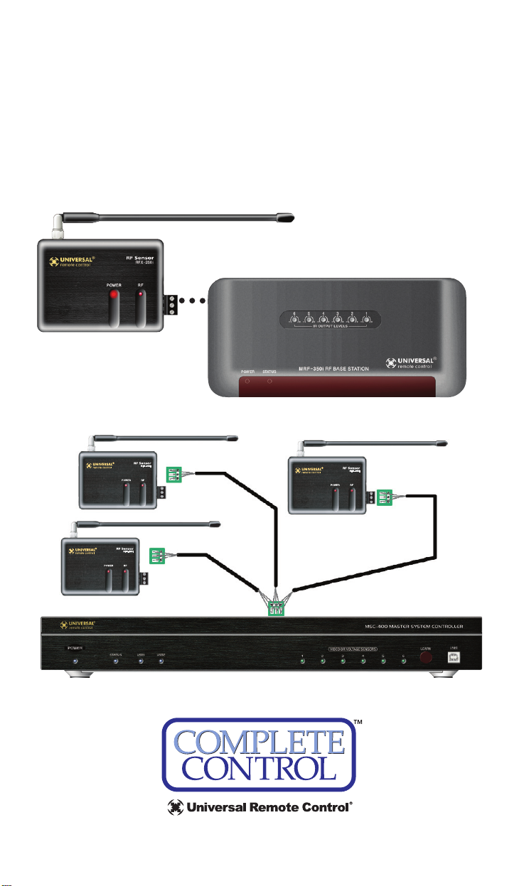
Overview - Compatibility
The RFX-250i is a 433MHz RF receiver. It connects to an MRF-350,
MRF-350i, MSC-400 or an MSC-400i. It is not compatible with all
URC remote controls. It is only compatible with “I” series remote
controls, which transmit at 433MHz.
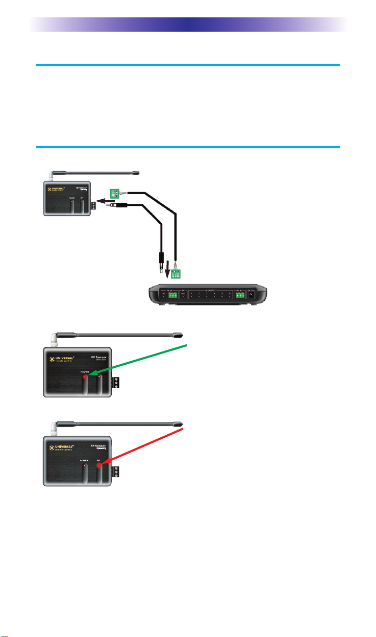
Connections
When the RFX-250i can be placed within 10 feet
of the MRF/MSC unit, you can utilize the cable
with 3.5 mm plugs on both ends. When you
need a longer wire or are connecting up to
three RFX-250i’s, use a cable with a minimum of
three conductors. If you use CAT 5,utilize two
conductors each from two of the twisted pairs
for DATA and two from the other twisted pairs
for 5V. Use all four of the other conductors
twisted in with each pair for GND.This provides
better shielding and conductivity for long runs.
Connect ONE (only)
of either of the RFX250i’s RF OUT connectors to ONE (only) of
either of the RF IN
connectors on the
MRF or the MSC.
Once the RFX-250i is correctly connected, the POWER LED lights.
If the RF LED lights, the RFX-250i must
be moved to a new mounting location. It
is receiving in-band RF INTERFERENCE.
 Loading...