

Page 1

Front Fork Kit for Yamaha R6
FGK 202
Mounting Instructions
Part No. Pcs.
Front fork kit FGK202 1
Sticker set Öhlins 1
Owners manual 07284-01 1
Warning!
This kit should only be installed by an
authorized Öhlins dealer. The installation
procedure requires certain tools.
Before installing this product, check the contents
of the kit. If anything is missing, please contact
an Öhlins dealer.
Kit Contents
Please note that during storage and
transportation, especially at high ambient
temperature, some of the oil and grease used for
assembling may leak and stain the packaging.
This is in no way detrimental to the product,
wipe off the excessive oil/grease with a cloth.
Warning!
Before installing this product, please read this
document. The front fork is an important part of
your vehicle and will affect the stability.
Note!
Please note that after this installation the
compression adjuster at the fork bottom will no
longer have a function.
Page 2
Safety Precautions
© Öhlins Racing AB. All rights reserved. Any reprinting
or unauthorized use without the written permission of
Öhlins Racing AB is prohibited.
Printed in Sweden.
Safety Symbols
In this manual, mounting instructions and
other technical documents, important
information concerning safety is
distinguished by the following symbols:
The Safety Alert Symbol means: Warning!
Your safety is involved.
Warning!
The Warning Symbol means: Failure to
follow warning instructions can result in
severe or fatal injury to anyone working
with, inspecting or using the front fork, or
to bystanders.
Caution!
The Caution Symbol means: Special
precautions must be taken to avoid
damage to the front fork.
Note!
The Note Symbol indicates information that
is important regarding procedures.
Note!
The front fork is a very important part of the
vehicle and will therefore affect the stability.
Read and make sure that you understand
the information in this manual before you use
this product. If you have any questions
regarding installation or maintenance please
contact your nearest Öhlins dealer.
Öhlins Racing AB can not be held
responsible for any damage to the front fork,
vehicle, other property or injury to persons, if
the instructions for installing and maintenance
are not followed exactly.
Warning!
This product was developed and designed
exclusively for a specic vehicle model and
should only be installed on the intended vehicle
model in its original condition as delivered from
the vehicle manufacturer.
After installing this product, take a test ride
at low speed to make sure that your vehicle
has maintained its stability.
Note!
When working on this product, always consult
your Vehicle Service Manual.
This Manual should be considered as a part
of the product and should therefore accompany
the product throughout its life cycle.
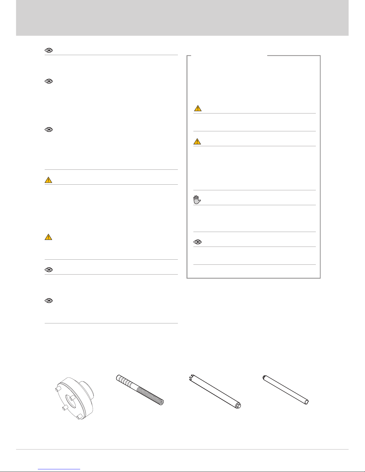
Tools
1
Tool 00797-08 Tool 01765-03 Tool 01797-07
Tool 04702-04
Page 3
Install Öhlins Front Fork Kit
6
tube. Torque 10 Nm.
3.15
Set the spring preload, rebound and
compression adjusters according to
adjustments and set-up data in this manual.
3.16
Install the front fork legs into the triple clamps
at the position recommended in set-up data
(Fork leg position).
Tightening torque: According to your vehicle
service manual.
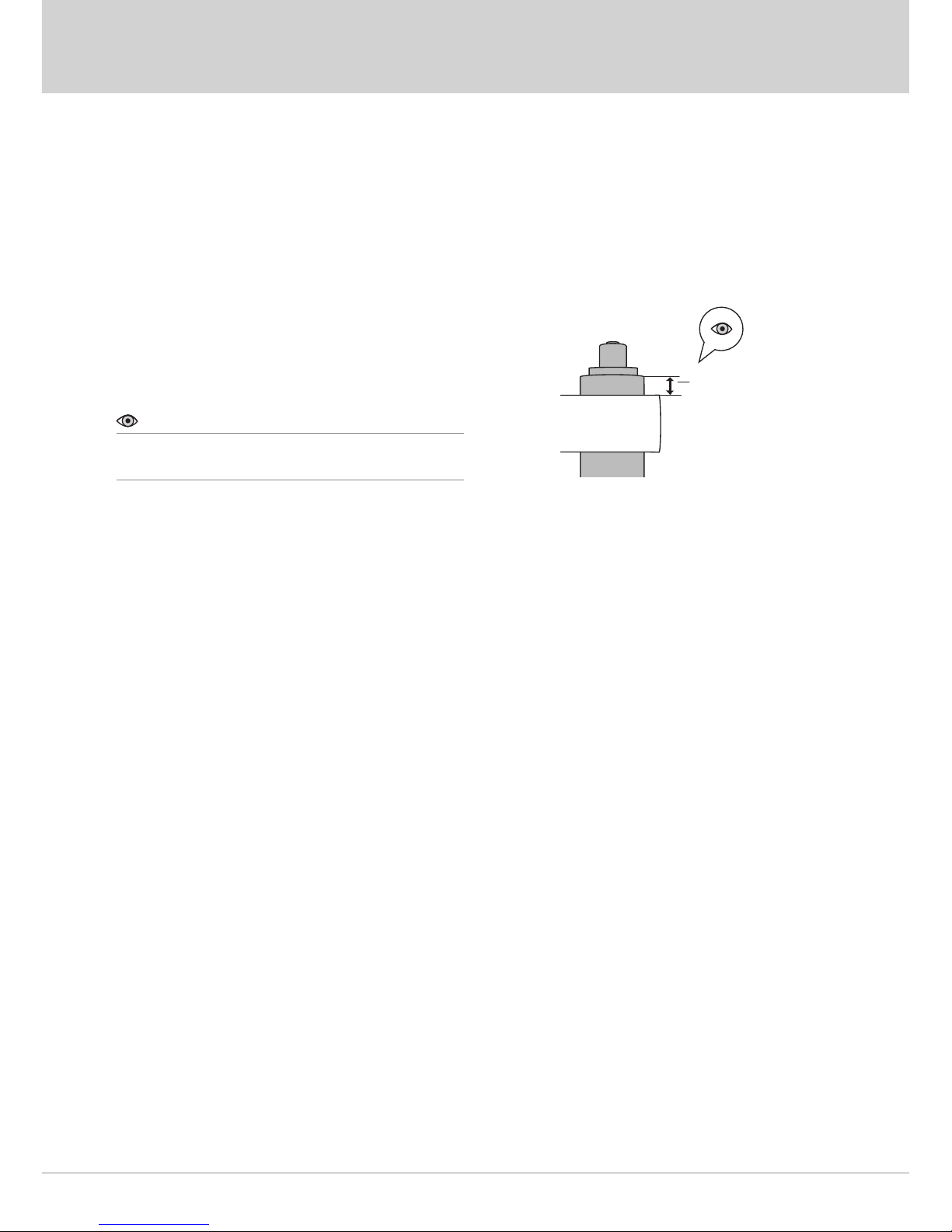
Note!
Measure the fork leg position from the upper
triple clamp to the top of the outer tube.
Fork leg
position
Page 4
3 - Install Öhlins Front Fork Kit
5
position and be careful not to damage it.
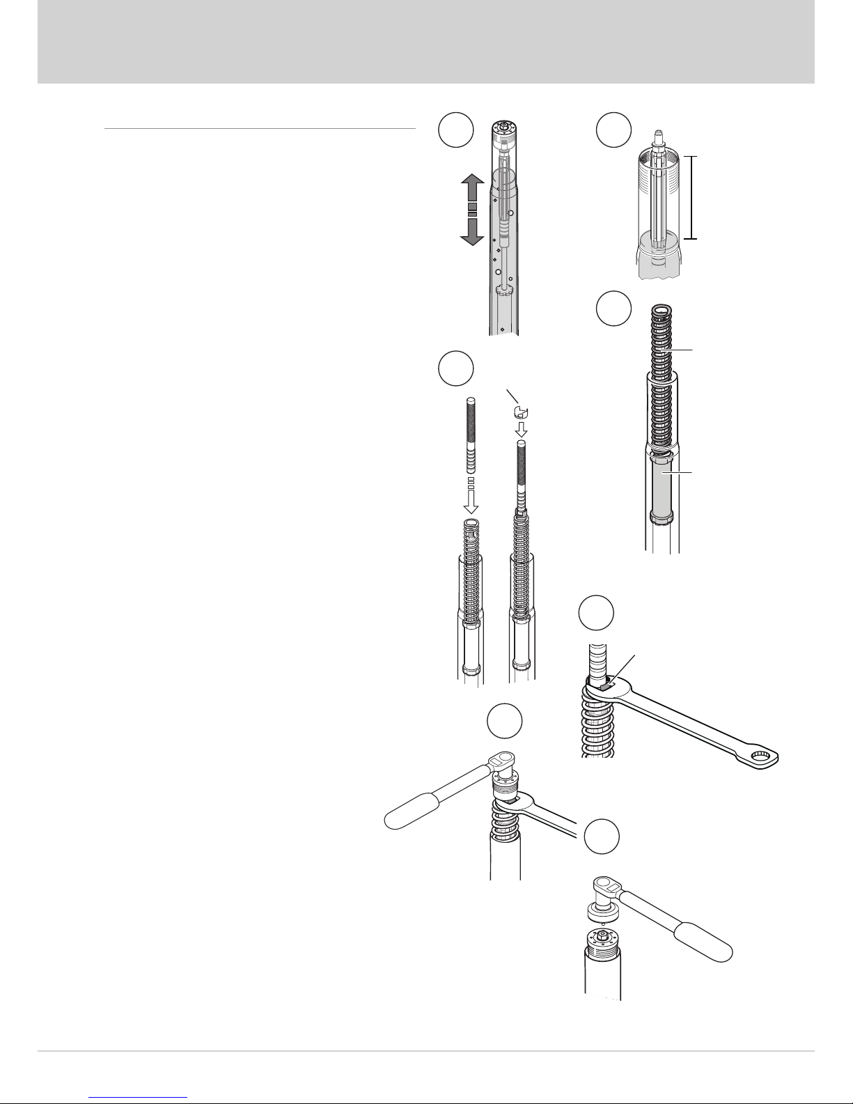
3.7
Open the compression and the rebound
adjuster fully. Install the top cap directly to the
shaft extension (No spring or preload tube).
Pull up the outer tube and tighten it to the top
cap. Handtighten only.
3.8
Pump out all air from the cartridge by pulling
the outer tube up and down 10-15 times.
3.9
Remove the top cap from the fork leg.
3.10
Make sure the shaft assembly is in the bottom
of the fork leg and that the outer tube is in its
bottom position. Measure the oil level with
a ruler. See set-up data and oil level-force
diagram in this folder.
3.11
Fasten tool 01765-03 on the top of the shaft
extensioner, install preload tube,spring and
upper spring support by leading them over the
tool. See the Owner’s Manual for available
springs.
3.12
Pull up the shaft assembly and grab the spring
support with a 19 mm wrench.
3.13
Make sure that the comp/rebound adjusters
are fully open before installing the top cap.
Remove the pull-up tool and install the top cap
to the shaft extensioner. Torque 15 Nm.
3.14
Pull up the outer tube. Make sure the fork
leg is in a fully extended position. Use tool
00797-08 to tighten the top cap to the outer
Spring
support
Spring
Preload
tube
Spring
support
XXX mm
8
11
10
12
13
14
11
Page 5
1 - Remove Original Front Fork
2
Warning!
It is advisable to have an Öhlins dealer install
the front fork.
When installing, consult your Vehicle Service
Manual.
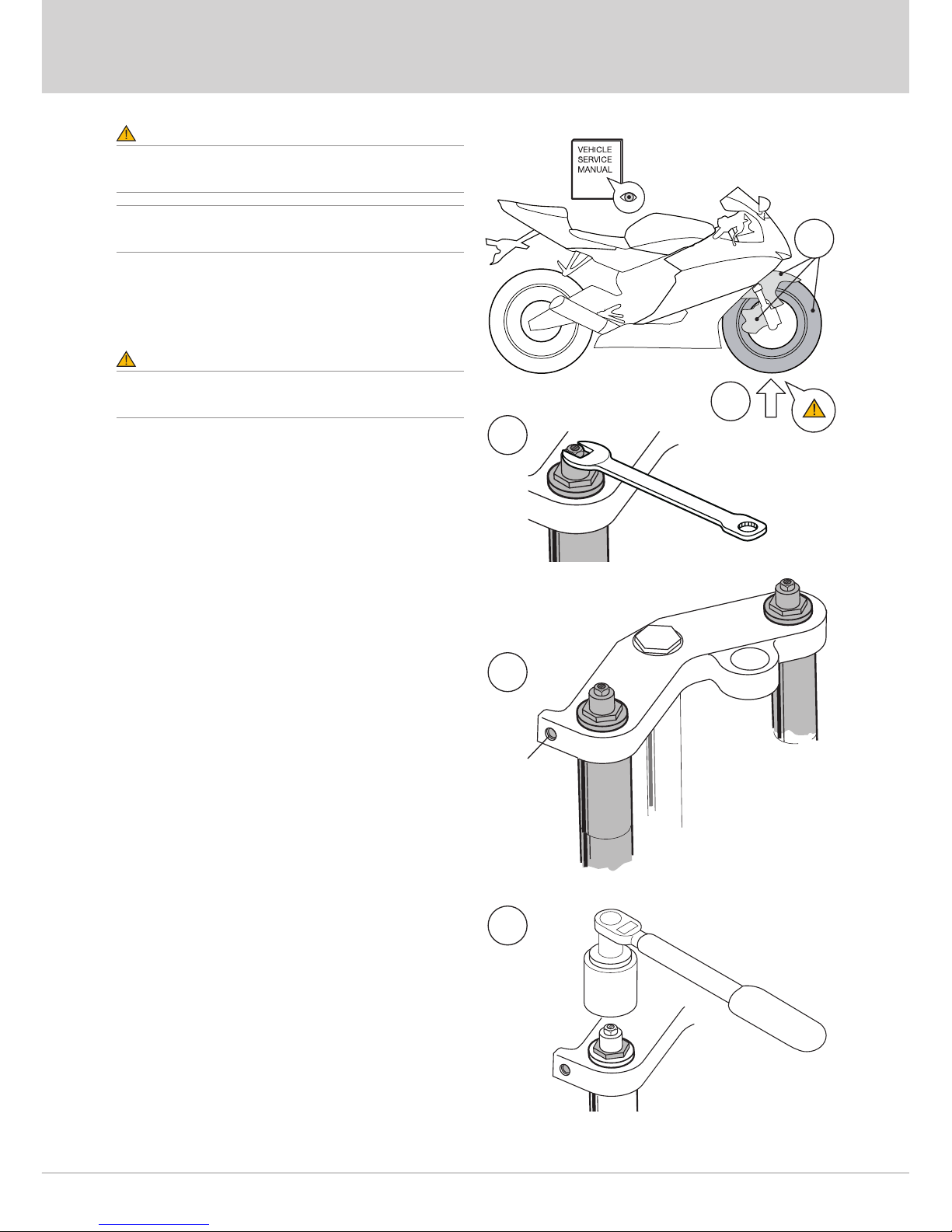
1.1
Put the motorcycle on a workstand so that the
front wheel barely touches the ground.
Warning!
Make sure the vehicle is securely supported so
that it will not tip.
1.2
Remove the front fender, the brake calipers
and the front wheel.
1.3
Release the spring preload.
1.4
Loosen the upper triple clamp by loosening
the screws.
1.5
Loosen (do not remove) the top cap ½ turn.
1.6
Loosen the lower triple clamp by loosening the
screws.
1.7
Remove the front fork legs from the fork triple
clamps.
Screw
1/2 turn
1
3
4
5
2
Page 6

3
2 - Disassemble Original Front Fork
2.1
Loosen the top cap from the outer tube.
2.2
Pull down the outer tube.
2.3
Remove the top cap by loosening it from the
shaft. Use appropriate tool according to your
vehicle service manual.
2.4
Remove the spring and surrounding parts
from the fork leg, drain the fork leg from oil.
2.5
Loosen the cartridge. Use tool 04702-04.
2.6
Remove the cartridge from the fork leg.
Page 7
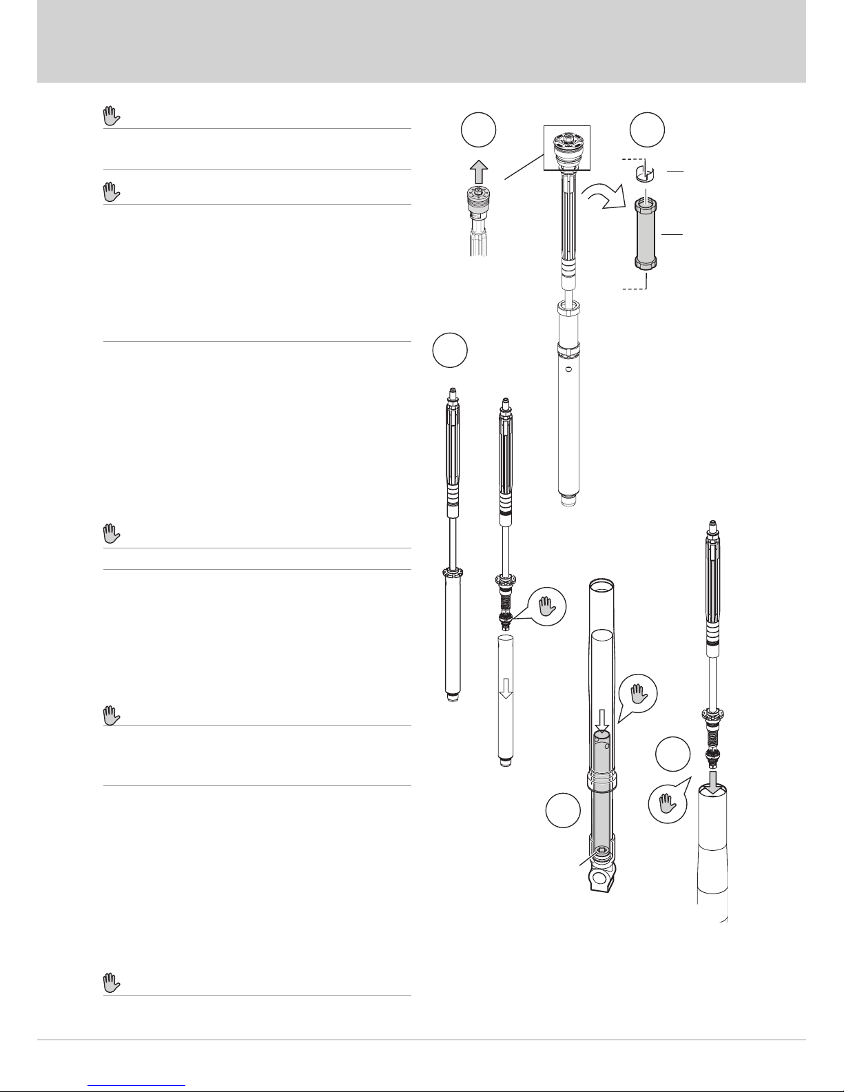
4
3 - Install Öhlins Front Fork Kit
Caution!
Work with only one fork leg at a time. Do not
mix the parts.
Caution!
The front fork kit is divided into one
compression cartridge and one rebound
cartridge. Important:
• Install the cartridge marked “Reb” (Rebound) in the
right side fork leg.
• Install the cartridge marked “Comp” (Compression)
in the left side fork leg.
3.1
Remove the top cap.
3.2
Remove the spring support and the preload
tube.
3.3
Remove the cylinder tube from the cartridge.
Caution!
Be careful not to damage the piston ring.
3.4
Put the cylinder tube carefully into the fork leg.
Use an extended 17 mm allen key to tighten
the cylinder tube’s adaptor to the fork bottom.
Apply Loctite 243 on the adaptor’s thread.
Torque 40 Nm.
Caution!
Be careful not to damage the inside of
the cylinder tube when tightening with the
extended allen key.
3.5
Pour 0,5 litre Öhlins Front Fork fuid into the
fork leg.
3.6
Put the cartridge carefully in the fork
leg. Tighten to the cylinder tube with tool
01797-07. Apply red grease on the seal
head’s thread. Torque 20 Nm.
Caution!
Make sure that the piston ring is in its correct
Spring
support
Preload
tube
1 2
3
6
4
17 mm
allen key
Page 8
Öhlins Racing AB
Box 722
S-194 27 Upplands Väsby, Sweden
Phone +46 8 590 025 00
fax +46 8 590 025 80
© Öhlins Racing AB. All rights
reserved. Any reprinting or
unauthorized use without the written
permission of Öhlins Racing AB
is prohibited.
www.ohlins.com
Öhlins products are subject to
continuous improvement and
development, therefore, although
these instructions include the most
up-to-date information available at
the time of printing, minor updates
may occur.
To nd the latest information
contact your Öhlins distributor.
Please consult your Öhlins dealer if
you have any questions regarding
the contents in this document.
Set-up Data
Part no. FGK202_5
Issued 2017-01-01
Recommended set-up:
Compression 12 clicks
Rebound 12 clicks
Spring rate 9,5 N/mm
Spring preload 12 mm
Oil level 160 mm
Fork leg position 1 ring
Öhlins Front Fork Fluid part no 01309-01
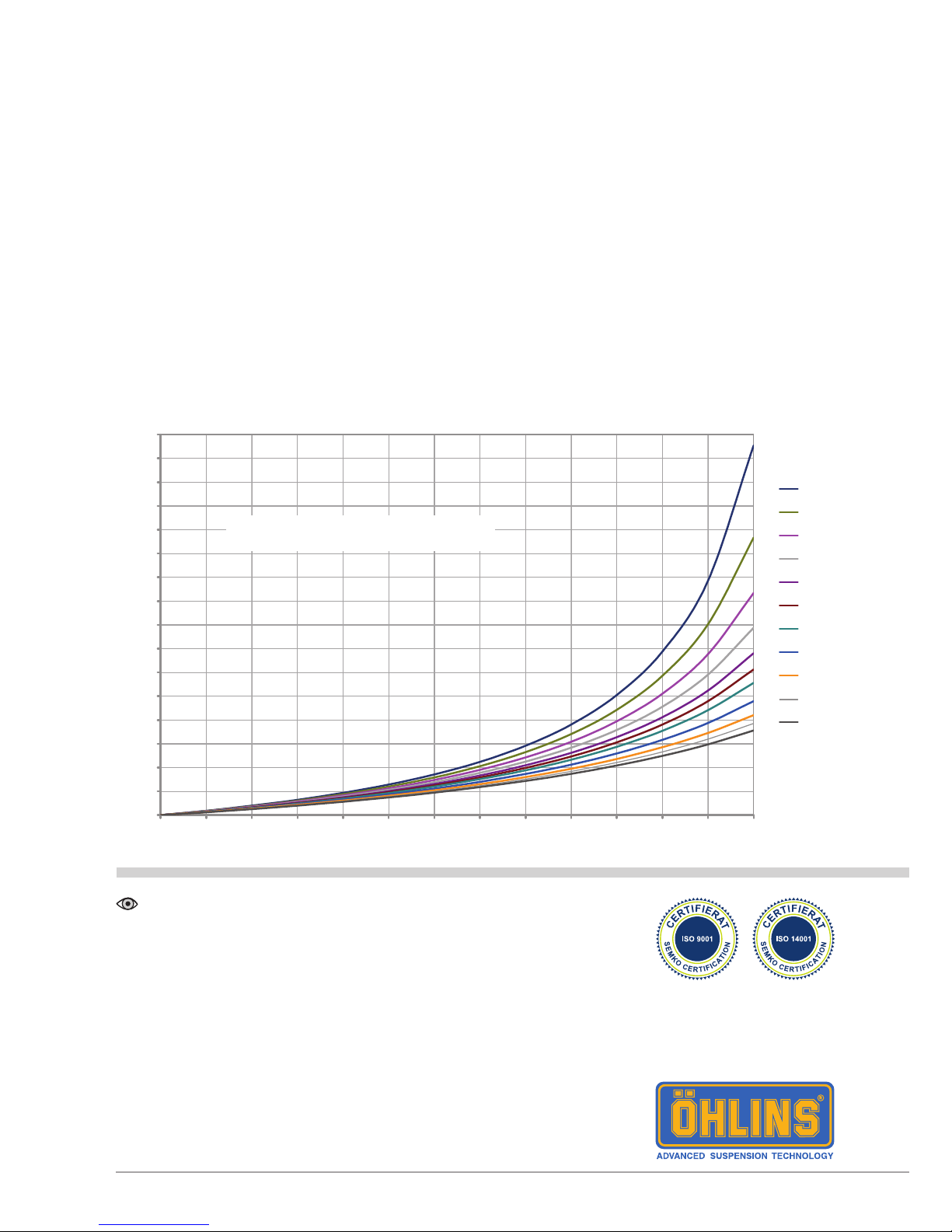
Diagram - Oil Level - Air Spring Force
0
50
100
150
200
250
300
350
400
450
500
550
600
650
700
750
800
0 10 20 30 40 50 60 70 80 90 100 110 120 130
Stroke [mm]
Force [N]
120
130
140
150
160
170
180
190
200
210
220
Oil level
(mm):
Air spring for one front fork leg
 Loading...