


Ohio Medical TS User manual

INSTRUCTION MANUAL
TS-Series Warming Cabinets
Installation - Operation - Maintenance
MAN-022 Rev E
OSHPD
R
C
Read and understand all of the instructions and safety
information in this manual before operating this product.
© 2017 MAC Medical, Inc.
Pre-Approved
12/2017

Instruction Manual
Table of Contents
Summary 3
TS-Series Warming Cabinet Models
General Specications
Main Features of a Typical Warming Cabinet
Warnings and Cautions
Unpacking Instructions
Installing TS-Series Warming Cabinets
Optional Direct Wiring Using Facility Power Supply
Basic Operation
The Touch Screen Interface
Quick Setup
Create Accounts (Admin Task)
User Login/Log Off
Navigation
Advanced Touch Screen Programming
User Accounts (Admin Task)
Audit Trail
Notications
Single and Dual Chamber Temperature Setting
Switching Temperature Units (Admin Task)
Data File Naming
Data Logging
Charts and Chart Setup
USB File Transfer
FTP/WAN Backup
Annotation
Digital Signatures
Alarm Function
E-mail Function
Communication Setting (Admin Task)
Clock Settings (Admin Task)
Language (Admin Task)
Offset Calibration (Admin Task)
Display Settings (Admin Task)
Conguration (Admin Task)
Exit Application (Admin Task)
Communications (Admin Task)
Using the Web Server
Using the VNC Server
Serial Communications Option
Installing the Shelves
Patient Safety - Maximum Warming Temperature Limit
Unloading the Warming Cabinet
Cleaning Stainless Steel Warming Cabinets
Preventative Maintenance Checklist
16
18
20
32
7
9
11
14
15
18
21
24
24
26
29
31
33
34
35
47
47
52
4
8
12
13
16
19
19
21
22
37
38
39
40
41
42
43
44
51
54
54
55
56
MAN-022
2
www.macmedical.com

Instruction Manual
Replacement Parts - General 57
Replacement Parts - Header Assembly and Electrical Drawer
Optional Cabinet Bases, Mobile Bases and Mobile Stands
Steel or Glass Door Hinge Reversal
Appendix A - System Security User Access List
Appendix B - Troubleshooting
TS-Series Electronic Connections Diagrams
Index
76
Preventative Maintenance Record
Notes
79
Limited Lifetime Warranty
Summary
80
61
70
72
74
78
58
60
DESCRIPTION OF PRODUCT
This manual covers the TS-Series (Touch Screen)
blanket and uid warming single and dual
chamber cabinet units, manufactured for
commercial use only.
PURPOSE OF THIS MANUAL
This manual is to provide the user instructions in
the installation, operation and maintenance of
the Touch Screen (TS) series warming cabinets.
This manual also contains general
specications, warnings and cautions.
MAN-022
3
www.macmedical.com
Instruction Manual
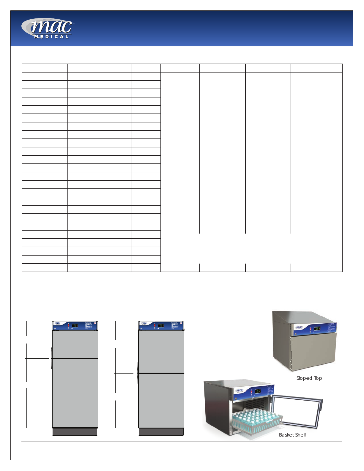
TS-Series Warming Cabinet Models
Model # Overall Size Chambers Door Type Door Hinge Base Style Other Options
SWC182424-TS 20.5"D x 24"W x 24.5"H Single G=Glass Door
SWC242424-TS 26.5”D x 24”W x 24.5”H Single
SWC183024-TS 20.5"D x 30"W x 24.5"H Single
SWC243024-TS 26.5"D x 30"W x 24.5"H Single
SWC183036-TS 20.5"D x 30"W x 36"H Single
Blank=Stainless
Steel Door
(Standard)
SWC243036-TS 26.5"D x 30"W x 36"H Single
SWC182464-TS 20.5"D x 24"W x 64.75"H Single
SWC242464-TS 26.5"D x 24"W x 64.75"H Single
SWC183064-TS 20.5"D x 30"W x 64.75"H Single
SWC243064-TS 26.5"D x 30"W x 64.75"H Single
SWC182474-TS 20.5”D x 24”W x 74.5”H Single
SWC183074-TS 20.5"D x 30"W x 74.5"H Single
SWC242474-TS 26.5”D x 24”W x 74.5”H Single
SWC243074-TS 26.5"D x 30"W x 74.5"H Single
DWC182464T-TS* 20.5"D x 24"W x 64.75"H Dual
DWC242464T-TS* 26.5"D x 24"W x 64.75"H Dual
DWC183064T-TS* 20.5"D x 30"W x 64.75"H Dual
DWC243064T-TS* 26.5"D x 30"W x 64.75"H Dual
DWC182474T-TS* 20.5"D x 24"W x 74.5"H Dual
DWC242474T-TS* 26.5"D x 24"W x 74.5"H Dual
DWC183074T-TS* 20.5"D x 30"W x 74.5"H Dual
DWC243074T-TS* 26.5"D x 30"W x 74.5"H Dual
ţOnly available for Dual Chamber Units
ţţOnly available for Single Chamber Units
DWC183074E-TS** 20.5"D x 30"W x 74.5"H Dual
DWC243074E-TS** 26.5"D x 30"W x 74.5"H Dual
LH=Left Hinge
Blank = Right
Hinge (Standard)
ţ2B = 2” Base
ţ4B = 4” Base
ţ6B = 6” Base
NB = No Base
MB = Mobile Base
220 = 220/240V
Power Supply
C = Celsius
R1 = Recessed
Unit with Insulation
Wrap, no Top Panel,
no Side Panels and
no Trim Kit.
R2 = Recessed Unit
with Top Panel, Side
Panels, and Trim Kit.
SB = Seismic Braces
WB = Roll Out
Basket
P = Pass Through
Chamber
ST = Sloped Top
ţţEL = Electronic
Keypad Lock
* = Chambers in Thirds ** = Equal Chambers
1/3
2/3
OFF
ON
1/2
1/2
OFF
ON
MAN-022
Sloped Top
Basket Shelf
4
www.macmedical.com

Interior Dimensions, Cubic Foot Capacity, Approximate Capacity
Instruction Manual
Instruction Manual
Model # Upper or single
Chamber
(h x w x d) in
inches
SWC182424-TS 15.25 x 20.0 x 17.0 n/a n/a 3.0 n/a n/a 9 blankets, 8 bottles
SWC242424-TS 15.25 x 20.0 x 23.0 n/a n/a 4.06 n/a n/a 9 blankets, 12 bottles
SWC183024-TS 15.25 x 26.0 x 17.0 n/a n/a 3.9 n/a n/a 18 blankets, 8 bottles
SWC243024-TS 15,25 x 26.0 x 23.0 n/a n/a 5.27 n/a n/a 18 blankets, 20 bottles
SWC183036-TS 25.0 x 26.0 x17.0 n/a n/a 6.39 n/a n/a 32 blankets, 36 bottles
SWC243036-TS 25.0 x 26.0 x 23.0 n/a n/a 8.65 n/a n/a 32 blankets, 40 bottles
SWC182464-TS 49.5 x 20.0 x 17.0 n/a n/a 9.74 n/a n/a 32 blankets, 48 bottles
SWC242464-TS 51.0 x 20.0 x 23.0 n/a n/a 13.60 n/a n/a 80 blankets, 120 bottles
SWC183064-TS 51.0 x 26.0 x 17.0 n/a n/a 13.05 n/a n/a 66 blankets, 72 bottles
SWC243064-TS 51.0 x 26.0 x 23.0 n/a n/a 17.65 n/a n/a 80 blankets, 120 bottles
SWC182474-TS 61.0 x 20.0 x 17.0 n/a n/a 12.00 n/a n/a 32 blankets, 60 bottles
SWC183074-TS 61.0 x 26.0 x 17.0 n/a n/a 15.60 n/a n/a 80 blankets, 72 bottles
SWC242474-TS 61.0 x 20.0 x 23.0 n/a n/a 16.24 n/a n/a 80 blankets, 120 bottles
SWC243074-TS 61.0 x 26.0 x 23.0 n/a n/a 21.1 n/a n/a 80 blankets, 120 bottles
DWC182464T-TS* 13.5 x 20.0 x 17.0 n/a 24.5 x 20.0 x
DWC242464T-TS* 13.5 x 20.0 x 23.0 n/a 24.5 x 20.0 x
DWC183064T-TS* 13.5 x 26.0 x 17.0 n/a 24.5 x 26.0
DWC243064T-TS* 13.5 x 26.0 x 23.0 n/a 24.5 x 26.0 x
DWC182474T-TS* 15.25 x 20.0 x 17.0 n/a 34.5 x 20.0 x
DWC242474T-TS* 15.25 x 20.0 x 23.0 n/a 34.5 x 20.0 x
DWC183074T-TS* 15.25 x 26.0 x 17.0 n/a 34.5 x 26.0 x
DWC243074T-TS* 15.25 x 26.0 x 23.0 n/a 34.5 x 26.0 x
DWC183074E-TS** 25.0 x 26.0 x 17.0 n/a 26.0 x 26.0 x
DWC243074E-TS** 25.0 x 26.0 x 23.0 n/a 26.0 x 26.0 x
Middle
Chamber
(h x w x d)
in inches
Lower
Chamber
(h x w x d)
in inches
17.0
23.0
x17.0
23.0
17.0
23.0
17.0
23.0
17.0
23.0
Cubic Foot
Capacity
Upper or single
Chamber
2.65 n/a 4.82 26 blankets, 36 bottles
3.59 n/a 6.52 52 blankets, 80 bottles
3.45 n/a 6.27 50 blankets, 54 bottles
4.67 n/a 8.48 52 blankets, 96 bottles
2.65 n/a 6.79 32 blankets, 48 bottles
4.06 n/a 9.18 52 blankets, 80 bottles
3.45 n/a 8.82 52 blankets, 72 bottles
5.28 n/a 11.93 52 blankets, 120 bottles
6.39 n/a 6.65 64 blankets, 72 bottles
8.65 n/a 8.99 64 blankets, 120 bottles
Cubic
Foot
Capacity
Middle
Chamber
Cubic Foot
Capacity
Lower
Chamber
Approximate
Capacity
(blankets & 1 Liter
solution bottles)
MAN-022
5
www.macmedical.com
Instruction Manual
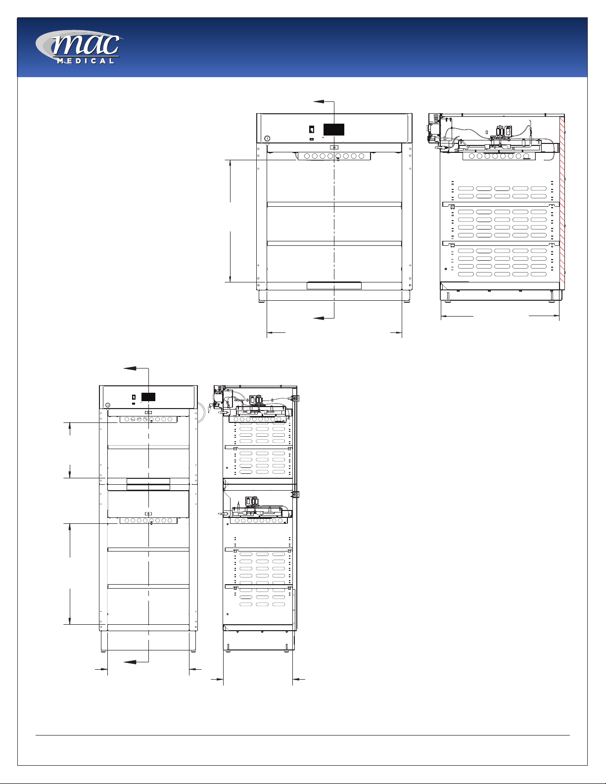
Usable Chamber Space
The usable chamber space of the
single, dual and triple cabinets
is slightly different from the
height, width, and depth interior
dimensions in the table on the
previous page.
Note that the usable chamber
inner height is measured from
the bottom of the air box to the
bottom of the chamber.
(In these views, the doors were
removed for clarity.)
A
USABLE
INNER HEIGHT
DIMENSION
A
A
CHAMBER WIDTH DIMENSION
Fig. 1: Single Chamber Unit Usable Space
CHAMBER DEPTH
DIMENSION
SECTION A-A
USEABLE
INNER HEIGHT
DIMENSION
USEABLE
INNER HEIGHT
DIMENSION
A
CHAMBER
WIDTH
DIMENSION.
Fig. 2: Dual Chamber Unit Usable Space
SECTION A-A
CHAMBER
DEPTH
DIMENSION.
MAN-022
6
www.macmedical.com

Instruction Manual
General Specications
Cabinet Construction and Material
• 300 Stainless Steel (all panels, header and doors) Double walled construction with insulation. Doors are
double pan stainless steel.
• Fully insulated to provide uniform heating
• Optional Glass door are double paned tempered glass framed with aluminum.
• Doors are fully gasketed and hinged on right side or optionally on the left side.
Factory Presets
• All units are preset to measure temperature in Fahrenheit (unless the unit was specically ordered to be
preset for Celsius.)
Power Requirements
• 120VAC, 60Hz, Single Phase, 15 AMP, Ground Fault Interrupter Circuit (GFIC) protected electrical outlet, or
220 VAC, 60Hz, Single Phase, 7 AMP, GFIC protected electrical outlet (by others) installed per local building
codes and provides protective earth.
• Cabinets are supplied with a 7 foot (2.3m) long, 14-3 SJT power cord with a 120V (NEMA 15P) hospital grade
plug. For multi-chambered units, ON/OFF switches are supplied for each chamber.
• All individual electronic components are Underwriter’s Laboratory (UL) approved and recognized.
Power Specications are located on the unit identication rating tag (Fig. 3) which is permanently attached on
the inside of the door or on the back of the upper chamber.
Electrical Specications by Model
Model # Description
SWC182424-TS 120V, 2.9 AMP, 50/60 Hz. .23 KWh (Avg.), 785 BTU/hr (Avg.)
Fig. 3: Power Specication Label
SWC242424-TS, SWC243024-TS,
SWC243036-TS
SWC183024-TS, SWC183036-TS 120V, 5.7 Amp. 50/60 Hz., .45 kWh (Avg.), 1535 BTU/hr (Avg.)
SWC182464-TS, SWC182474-TS,
SWC183074-TS, SWC242474-TS
SWC243074-TS
SWC183064-TS 120V, 6.3 Amp, 50/60 Hz, .41 kWh (Avg.), 1400 BTU/hr (Avg.)
SWC242464-TS, SWC243064-TS 120V, 6.5 Amp, 50/60 Hz, .41 kWh (Avg.), 1604 BTU/hr (Avg.)
SWC182464-TS, SWC182474-TS,
SWC183074-TS, SWC242474-TS,
SWC243074-TS,
DWC183064T-TS, DWC242464T-TS 120V, 8.3 Amp., 50/60 Hz, .60 kWh (Avg.), 2047 BTU/hr (Avg.)
DWC182464T-TS, DWC182474T-TS,
DWC243064T-TS, DWC242474T-TS
DWC183074T-TS 120V, 8.3 Amp. 50/60 Hz, .82 kWh (Avg.) 2047 BTU/hr (Avg.)
DWC183074E-TS 120V, 11.4 Amp. 50/60 Hz, .82 kWh (Avg.) 2798 BTU/hr (Avg.)
DWC243074T-TS 120V, 12.5 Amp. 50/60 Hz, .90 kWh (Avg.) 3071 BTU/hr (Avg.)
DWC243074E-TS 120V, 12.9 Amp. 50/60 Hz, .90 kWh (Avg.) 3071 BTU/hr (Avg.)
120V, 6.3 Amp, 50/60 Hz, .45 KWh (Avg.), 1535 BTU/hr (Avg.)
120V, 6.5 Amp, 50/60 Hz, .47 KWh (Avg.), 1604 BTU/hr (Avg.)
120V, 6.5 Amp, 50/60 Hz, .47 kWh (Avg.), 1604 BTU/hr (Avg.)
120V, 8.9 Amp., 50/60 Hz, .65 kWh (Avg.), 2218 BTU/hr (Avg.)
MAN-022
7
www.macmedical.com
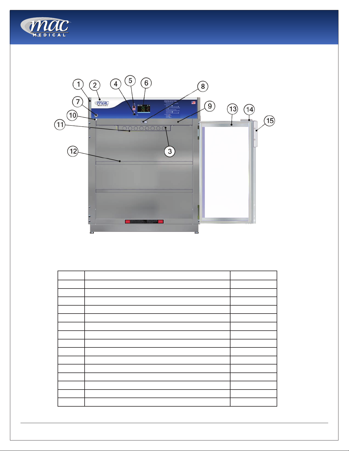
Main Features of a Typical Warming Cabinet
(Single Chamber Cabinet shown here)
Instruction Manual
Fig. 4: Warmer Cabinet Main Features
This list shows the main elements of a warming cabinet. For a list of replacement parts with their part numbers
and quantities, see”Replacement Parts - General” on page 57 and “Replacement Parts - Header Assembly
and Electrical Drawer” on page 58.
Item # Description Qty
1 Header Assembly (24” and 30”) 1
2 Overlay (24” and 30”) TS-series 1
3 Air Box 1 per chamber
4 USB cable plug 1
5 On/Off Switch 1
6 Touch Screen Display Board
7 Key Lock 1
8 Door Switch 1 per chamber
9 Drawer Assembly 1 per chamber
10 Cam Lock Latch 1 per door
11 Probe J Type Thermocouple 1 per chamber
12 Adjustable Perforated Shelf As Required
13 Door (glass or steel) As Required
14 Cam Lock Plate 1 per door
15 Handle 1 per door
1
MAN-022
8
www.macmedical.com
Instruction Manual
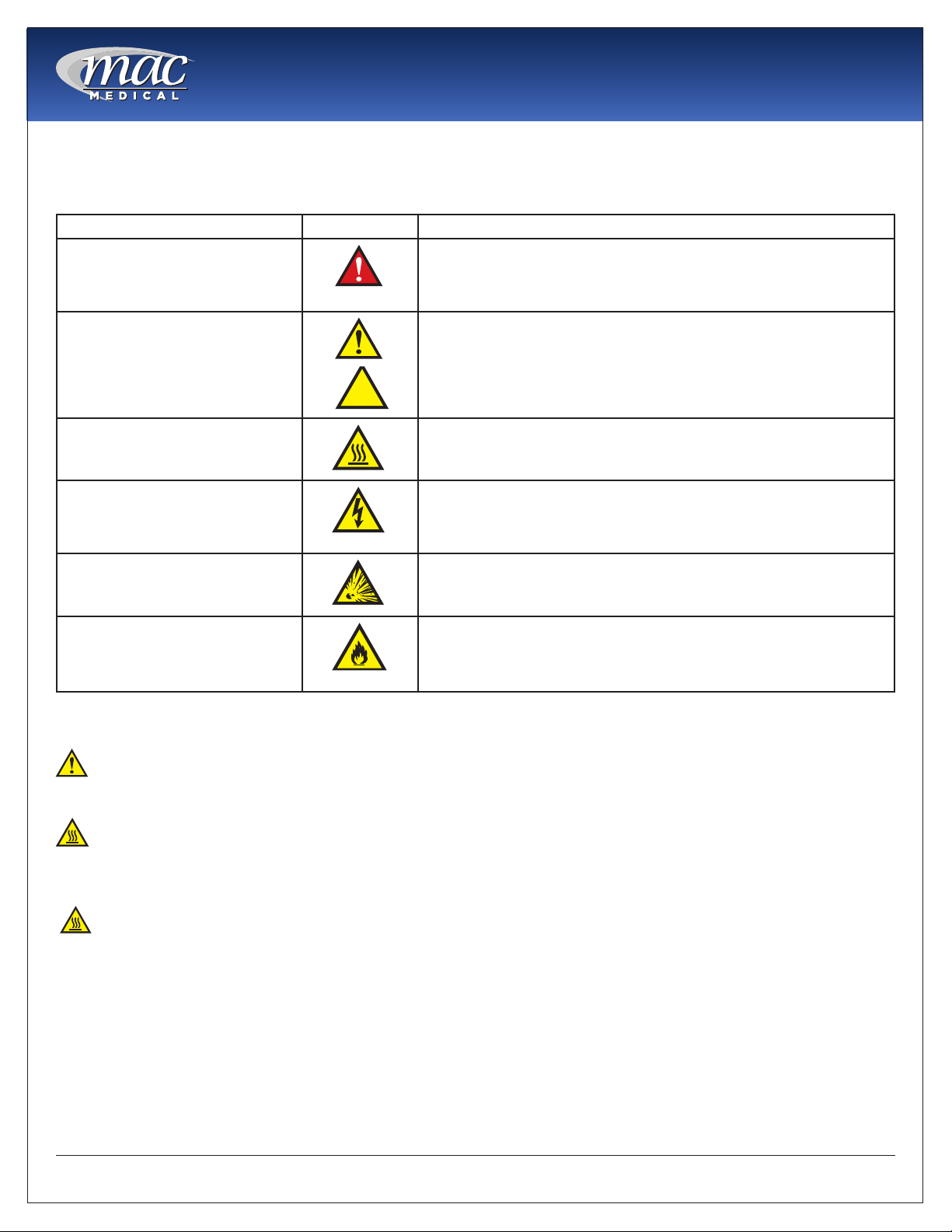
Warnings and Cautions
The following is a list identifying the various warning and caution icon used in this manual.
Icon Type Icon Description
Warnings
(Red triangle with an exclamation point) indicates the potential for
minor to severe injuries up to and including death to personnel.
Cautions
Burn Hazard Warnings
Electrical Warnings
Explosion Hazard
Fire Hazard
(Yellow triangle with an exclamation point) indicates the potential
minor injury to personnel and damage to equipment.
Note: The exclamation point will not be visible where only
equipment damage is present.
(Yellow triangle with radiating lines) indicates a potential burn injury
to personnel.
(Yellow triangle with a lightning bolt) indicates a possible shock
hazard is present. Severe shock hazards shall be a lightning bolt in a
red triangle.
(Yellow triangle with the explosion icon) indicates the equipment
should not be operated in areas where explosions could occur.
(Yellow triangle with the re icon) indicates the warning cabinet
should not be loaded with materials or liquids that are ammable or
use in the presence of ammable anesthetics or solvents.
The following is a list of safety precautions that must be observed when operating this equipment.
Warning - Injury Hazard
REPAIRS AND ADJUSTMENTS should be attempted only by experienced service representatives. Use of
unqualied persons to work on this equipment could result in personal injury or costly damage.
Warning - Burn Hazard
• Do NOT use in the presence of ammable anesthetics.
• Do NOT heat liquids in the presence of ammable solvents.
• Failure to observe this Warning can result in severe personal injury and even death.
Warning - Burn Hazard
• Do NOT exceed 150° F (65.56 C) for non-vented closures; (screw caps, crimp seals, plastic pouches, etc.).
Do not exceed pre-sterile solution manufacturer’s temperature requirements.
• Do NOT raise set temperature to increase rate of heating. Allow approximately 4-6 hours for solutions to
reach desired temperatures.
• Do NOT use liquids on or inject into living tissue, unless actual liquid temperature has been measured
and is acceptable. Temperature of the warming cabinet’s contents may be hotter than the displayed
air temperature. For patient safety, in accordance with good medical practice, always check liquid
temperature prior to using.
MAN-022
9
www.macmedical.com
Instruction Manual
Warning - Electric Shock Hazard
Do NOT remove control tray. Contact a qualied service representative. Some of the troubleshooting
procedures can require access to live electrical circuitry. Dangerous accidental contact with line voltage is
possible. Only qualied service personnel should be allowed to perform these procedures.
Warning - Explosion Hazard or Fire Hazard
• Do not warm ammable materials or liquids.
• Do Not use in the presence of ammable anesthetics.
• Do Not heat liquids in the presence of ammable solvents.
Caution - Possible Equipment Damage
Some items are not acceptable in these warming cabinets. If in doubt as to whether an item can be safely
processed, have the facility supervisor contact the manufacturer of the item.
Caution: Repairs And Adjustments should only be attempted by experienced service personnel who are
fully acquainted with this equipment. Use of unqualied or inexperienced personnel to work on the equipment,
or the installation of unauthorized parts, could result in serious personal injury, or result in costly damage. Always
unplug power cord from power source before attempting any repairs or servicing of this equipment.
Special User Attention
Prior to use, all personnel who will operate the Warming Cabinet must be instructed in the correct usage and
operation. All personnel who will use the Warming Cabinet should be aware that sensible care must be
exercised to maintain patient safety and to keep the Warming Cabinet performing at peak efciency.
Intended Use Notice
This product is intended to be used by medical personnel for the purpose of providing heated storage of
blankets, sterile water and saline solutions used in the care of patients in surgery, recovery, OB/GYN, ICU,
ER and trauma areas in healthcare facilities where al operators are instructed on the usage, limitations and
hazards. No other use is authorized or recommended.
This product is to be used strictly for the purpose for which it was designed. Using this product in a manner
not specied by MAC Medical, Inc. can void the protection provided by the equipment manufacturer. MAC
Medical, Inc. disclaims all liability for the consequences of this product being used for other than what it was
designed for. Product modication or misuse can be dangerous. MAC Medical, Inc. disclaims all liability for
the consequences of product alterations or modications, as well as for the consequence that can result
from the combination of this product with other products, whether supplied by MAC Medical, Inc. or by other
manufacturers, unless such a combination has been specically endorsed, in writing, by MAC Medical, Inc.
MAN-022
10
www.macmedical.com
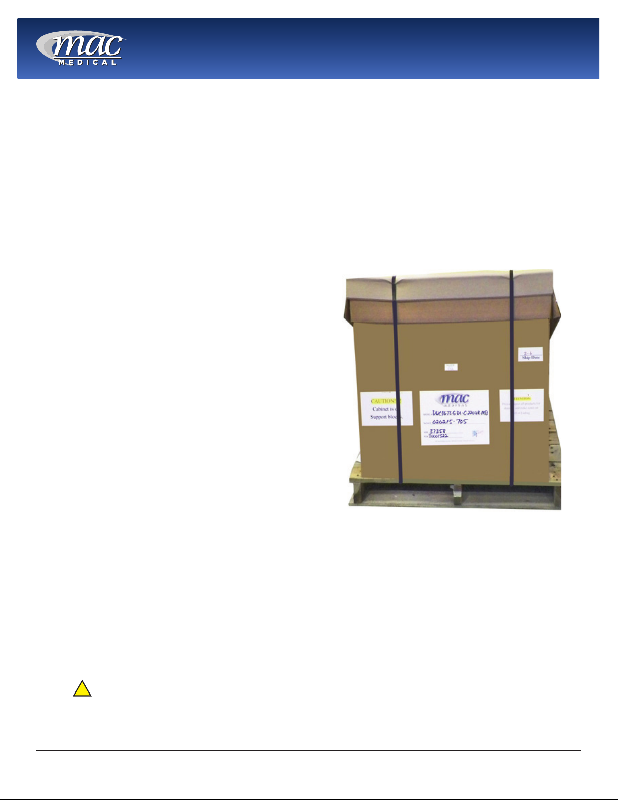
Unpacking Instructions
Receiving Requirements
The customer is responsible for making sure the
loading dock at their facility can accommodate a
shipping carton approximately 70” inches (1.778m)
long and 40” (1.016m) inches wide.
The customer must also provide transportation
equipment (forklift, etc) for a carton weighing
approximately 500 lbs (227 kg).
Inspection
1. Receiving area must meet all State and Local
regulations prior to unpacking.
2. Customer must inspect carton both before and
after unpacking to determine if any items were
damaged during shipping.
A. All damaged items must be listed on the Bill of
Lading.
B. The serial number and model number shown
on the carton label must match the numbers
on the Bill of Lading and the Invoice.
3. Customer is responsible for the proper disposal of
all packing materials. The disposal of these items
must meet all State and Local regulations.
Instruction Manual
the protective coating on the stainless steel
allowing the surface to rust.
9. The Warming Cabinet is now ready for use.
10. Discard shipping and packing materials in
compliance with Local and State regulations.
11. Warmers, when not in use, must NOT be doublestacked while in storage. Warmers, while still in
shipping cartons must not be double-stacked
when not in use.
Unpacking the Warming Cabinet
Retain all shipping materials until warming cabinet is
completely unpacked and inspected for damage.
1. Remove metal bands holding the bottom and
top of the shipping carton together.
2. Remove all metal staples holding the top and
bottom of the carton to its sides.
3. Remove the top of the carton.
4. Remove metal staples making the aps around
the top edge of the carton.
5. Remove metal staples attaching the sides of the
carton to the bottom of the carton.
6. Remove the sides of the carton by lifting them
straight up from the bottom tray.
7. Lift Warmer straight up from bottom tray of the
shipping carton and remove it.
8. Remove all protective packing material.
A.
Caution: DO NOT use a box cutter or
any other cutting utensil to remove the
plastic protective wrapping around the
Warming Cabinet. These items can scratch
Fig. 5: Warming Cabinet in Shipping Container
MAN-022
11
www.macmedical.com

Installing TS-Series Warming Cabinets
Environmental Conditions
This unit is intended for use in a stable ambient
environment, with an ideal temperature of 72° F
(22.22° C) or less. The unit should never be used
directly next to any appliance that may produce
heat, such as an autoclave.
If the unit location must be near an autoclave
or similar heat producing appliance, action or
modications must be taken to prevent heat transfer
and allow proper operation. Contact MAC Medical,
Inc. for information.
During Transport and Storage (in original packaging
materials) -
• Ambient Temperature: -40° - 159°F (-40° - 70°C)
• Relative Air Pressure: 10% - 100%, including
condensation
• Air Pressure: 500 hPa (14 inHg - 31.3 inHg)
During Use - for Dry Locations
• Ambient Temperature: 60° - 85°F (15° - 30°C)
• Relative Air Moisture: 30% - 60% non-condensing
• Air Pressure: 700 hPa - 1060 hPa (20.7 inHg - 31.3
inHg)
Installation
Before starting the installation, review the local
electric codes including the Occupational Health
and Safety Act for any requirements pertaining to the
proper installation of this equipment.
Contact your MAC Medical representative for seismic
calculations and tie-down hardware, if applicable.
Instruction Manual
1. Carefully uncrate the TS-Series Warming Cabinet.
2. Inspect for any damage. If there is damage,
please contact MAC Medical, Inc. at (1-877-828-
9975).
3. Check your 120V, 60 Hz, Single Phase 15 AMP
GFIC Protected electrical outlet or 220V, 60 Hz,
Single Phase, 7 AMP GFIC Protected electrical
outlet. Be sure the outlet is safely accessible and
in proper working condition.
4. Plug the 3-prong electrical plug into the 120VAC,
60Hz, 15 AMP, GFIC Protected Outlet or a 220
VAC, 60Hz, Single Phase, 7 AMP GFIC protected
electrical outlet. Make sure the electrical outlet is
safely accessible and in proper working condition.
5. Place Warming Cabinet on a solid, level platform
where external movement will not interfere with
loose contents used by the warmer.
6. Make sure the shelving is correctly located as
desired and level. If not, adjust their height (see
“Adjusting the Shelves” on page 52).
7. Before use, remove any items that have been
stored in the cabinet.
Testing before Using
All warming cabinets have been calibrated and
tested before leaving the factory. There is no need
for the user to do additional testing after installation
prior to use.
After six month of use, it is recommended that the
user test the warming cabinet for temperature
accuracy. See “Preventative Maintenance
Checklist” on page 56.
MAN-022
12
www.macmedical.com
Instruction Manual
2
5
2
3
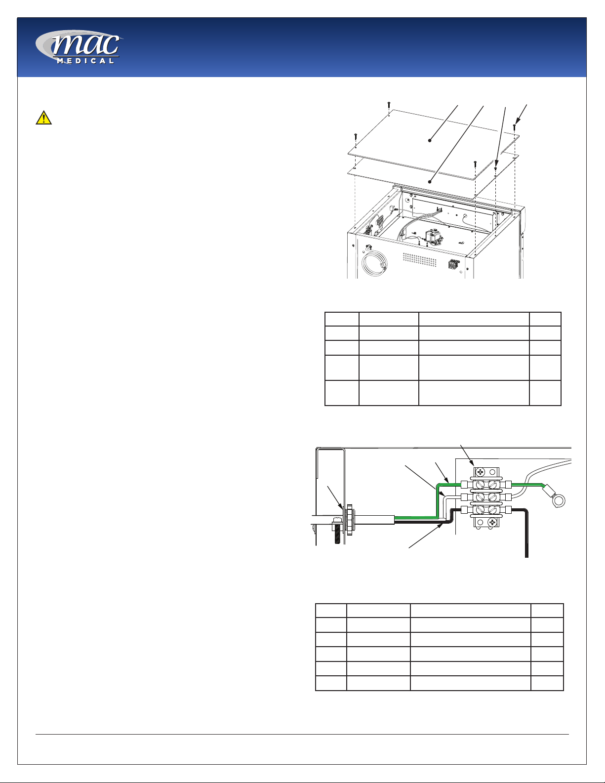
Optional Direct Wiring Using Facility Power Supply
NOTE: The following procedure must be
performed by a qualied electrical technician to
avoid personal injury or damage to the unit.
Warming Cabinets can be wired directly into the
facility’s wiring by following these steps:
1. Remove four 8 X 1-5/8” self tapping screws and lift
off the Top Outer Panel. See Fig. 6.
2. Remove two 8 X 1/2” self tapping screws and lift
off the Top Inner Panel. See Fig. 6.
3. Loosen the 3/8” straight-thru connector (See
Figure 4, Item 1) and disconnect wiring from
terminal board (Figure 4, Item 5) and from Fig. 7,
Items 2, 3, 4.
4. Remove existing power cable (See Figure 4, Items
2, 3, and 4) from terminal block and pull out of
Warming Cabinet through 3/8” connector (See
Fig. 7, Item 1).
5. Feed facility wiring cable back through the 3/8”
connector (See Fig. 7, Item 1) in the back of the
cabinet and wire onto terminal board as shown in
Fig. 7. Tighten the 3/8” to securely hold the facility
wiring in place.
6. On the terminal board, The green wire (Item 4)
connects with the green ground wire.
7. The white wire (Item 3) connects opposite with
the white wire, or neutral wire, on the terminal
board.
8. The black wire (Item 2) connects opposite of the
black or positive wire on the terminal board.
9. Re-install the Inside Top Panel using two 8 X 1/2”
self-tapping screws. See Fig. 6.
10. Re-install the Outside Top Panel using four 8 X
1-5/8” self-tapping screws. See Fig. 6.
11. Carefully slide the unit into its permanent location.
1
Fig. 6: Remove Top Covers
Item P/N Description Qty
1 SMW0027 Outside Top Panel 1
2 SMW0028 Inside Top Panel 1
3 H0012-01 Screw, Self-Tapping, 8
X 1/2”
4 H0012-02 Screw, Self-Tapping, 8
X 1-5/8”
3
4
1
Fig. 7: Unwiring Terminal Block
4
2
4
MAN-022
Item P/N Description Qty
1 W0140 Connector, Straight, 3/8” 1
2 W0077 Wire, Black, Positive 1
3 W0077 Wire, White, Neutral 1
4 W0077 Wire, Green, Ground 1
5 W0005 Terminal Strip, 3-Position 1
13
www.macmedical.com
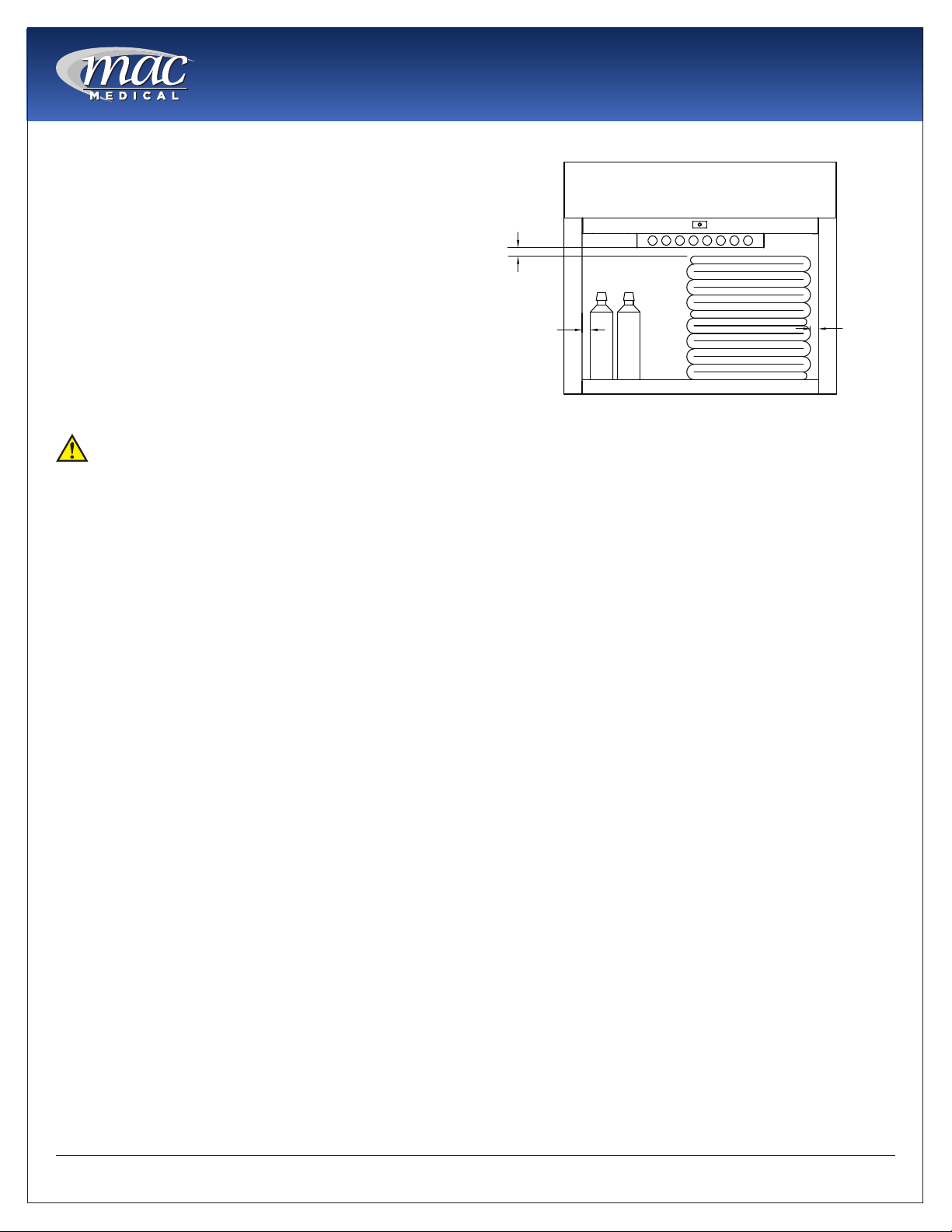
Basic Operation
1" OF
1" OF
SPACE
SPACE
1" OF
SPACE
This cabinet has been designed to heat:
• Liquids in vented containers.
• Liquids in non-vented containers to a temperature
of 150° F maximum (65.6°).
• Metal objects
• Muslin or 100% cotton sheets and wool blankets.
• Glass containers must be annealed borosilicate
glass (Pyrex type).
• Only plastic containers rated Thermal and
capable of withstanding temperatures in excess
of 300° F (149° C)
DO NOT WARM -
• Synthetic blend fabrics
• Flammable liquids
• Items containing non-thermal plastic, rubber,
metal snaps, studs, hooks, etc.
Recommended Settings
MAC Medial, Inc. does not recommend chamber
set points for any items that are to be warmed. For
appropriate heating temperatures, please contact
the item manufacturers. For more information, please
contact MAC Medical, Inc.
For blankets, follow blanket manufacturer’s
instructions for the set point.
For intravenous and irrigation uids, follow
temperature guidelines printed on the container or
contact your supplier for temperature and expiration
periods.
Instruction Manual
Fig. 8: Content Spacing
Once a set temperature is selected and obtained it
will be controlled throughout the operations within
± 1°F to 3°F (-17.2°C to -16.1°C) of the selected
temperature.
From a cold start, each compartment’s loaded
contents will be evenly heated to a setpoint within 2
to 6 hours (depending on the load). In the event of
power loss, the warmer will resume normal function
once power is restored.
For multi-chambered units, each chamber can be
loaded with different goods and set at different
temperature settings.
In Case of Power Failure
In case of power failure, the unit will resume normal
operation when power is restored.
Follow the uid manufacturer’s guidelines for unused
solutions that have cooled or have been removed
from heated storage.
Loading Contents in Cabinet
Load contents into the chamber with a minimum of 1
inch of space between all walls and fan to allow for
evenly distributed circulation (as seen here).
Allow 1” of spacing between uid containers for
evenly distributed heating (Fig. 8). Avoid stacking
uid bags as this increases the heating time required
to achieve set temperatures.
Blankets must be folded and stacked to allow a one
inch minimum space from the sides, back and top
of the compartment or the shelf above. Do not let
blanket protrude past the front edge of the shelf.
DO NOT OVERLOAD.
MAN-022
14
www.macmedical.com
Instruction Manual
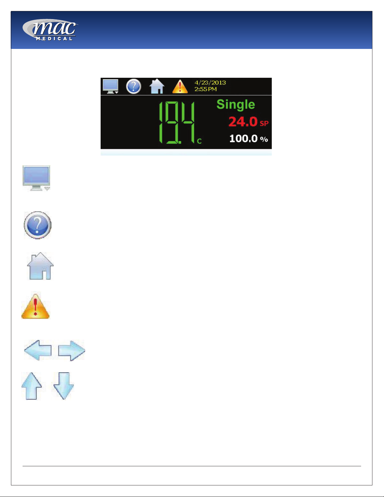
The Touch Screen Interface
The Touch Screen display is split into two sections: the icon bar and main display area.
Icon Bar
Main Display
Fig. 9: Touch Screen Explanation
The menu icon will open the main menu for navigating to the different control and
monitoring screens. Menu items will dynamically appear providing available options
based on the system area the user is in, i.e., security, data logging, setup, etc.
The information (help) icon will display text based help associated with the current screen.
Help is available in 28 languages based on the user selection in the ofine setup of
section of Touch Screen.
The home icon will return the user to the main view from anywhere in the Touch Screen
application. The main view is set by the OEM in the Touch Screen conguration and can
be the single or dual loop, chart, alarm, alarm history, event or digital IO view.
The alarm icon will appear and ash when a new system alarm occurs. Pressing the alarm
icon will take the user directly to the alarm monitor screen in order to view and /or reset
the active alarm condition.
The left and right navigation arrows will appear on screens that provide additional
information that the user can scroll to such as the loop view screens, charts or program
entry screen in order to cycle through each step of a ramp/soak program.
The up and down navigation arrows will appear on screens that provide list views in order
to scroll up and down through items of the list. List views also provide “touch sliding” like
other modern smart devices.
Note: A single press of the left/right or up/down arrows will scroll list views to the next list item, program steps to
the next step or screens to the next available loop or chart. Pressing and holding the arrow keys will continue
the item scrolling until the end of the list is reached or the button is released.
Important: Do not use any sharp or metal objects on the touch screen as they may damage the surface. Also
be sure that hands and ngers are free from oils or chemicals which may mar the surface of the touch screen.
MAN-022
15
www.macmedical.com
Instruction Manual
Quick Setup
Create Accounts (Admin Task)
Note: Pre-congured Administrator only utilities are
agged as (Admin Task) throughout the programming
sections of this manual and will require additional log
in to access the utility. The administrator can later
assign user rights to these utilities as needed.
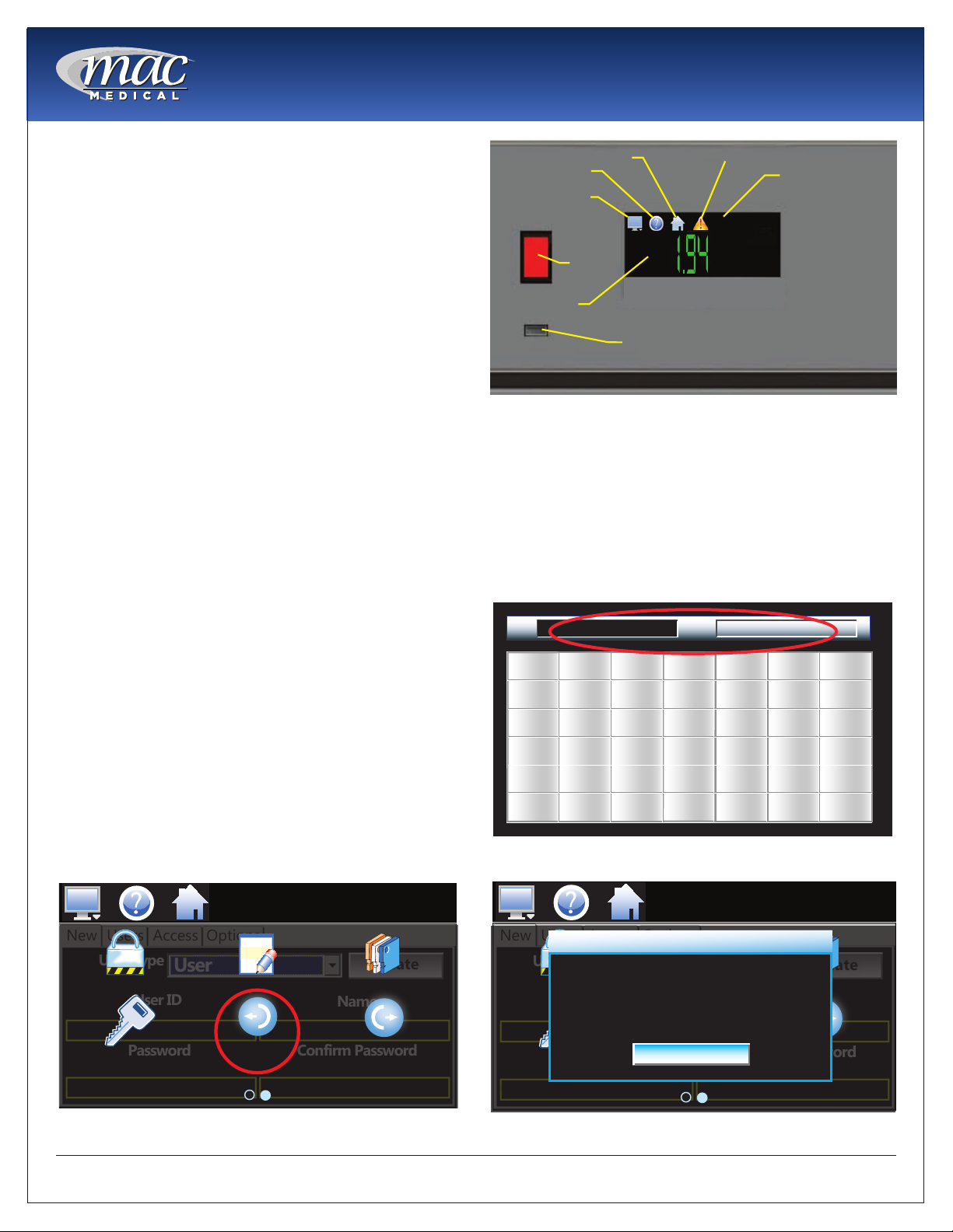
INFORMATION
(HELP) ICON
MONITOR or
Display ICON
OFF
ON
HOME SCREEN
HOME ICON
ON/OFF
SWITCH
Manual Control Automatic Tune
ALARM ICON
4/23/2013
4:54 PM
LOOP 1
24.0
100.0
C
DATE AND TIME
SP
%
Switch On
1. Plug the 3-prong electrical plug into the 120VAC,
USB PORT
60Hz, 15 AMP, GFIC Protected Outlet or a 220
VAC, 60Hz, Single Phase, 7 AMP GFIC protected
electrical outlet. Make sure the electrical outlet is
Fig. 10: TS Series Controller Interface Screen
safely accessible and in proper working condition.
2. Switch on the Warming Cabinet by pressing in the
ON side of the ON/OFF switch. Touch screen will
light up for use. (Fig. 10)
Set up Default Supervisor Account
When using the Warming Cabinet for the rst time, a default supervisor must be set up and logged in.
NOTE: When setting up accounts through the set up process, every entry must be minimum of 5 characters.
3. Default Supervisor Account Setup: Press HOME,
then MONITOR icons. Swipe the screen left to
right to go to the LOGIN icon (Fig. 11). Press this
icon to open the log in module.
4. A keyboard screen appears next. Touch USER
box and enter default supervisor name “Super”.
(Fig. 12).
5. Touch the PWD box and enter default password
“1-2-3-4-5” in PWD box (Fig. 12). Password
displays as *****. Press DONE.
6. Supervisor login conrmation appears. Press OK
(Fig. 13).
4/10/2015
1:51 PM
New
Users
Access
User Type
Configure Audit User
User ID
Password Confirm Password
Password Login Log Off
User
Options
Create
Name
User
A
E
I
M
Q
U
Fig. 12: Enter Default Supervisor in Keyboard
SUPER
B
F
J
N
R
V
Pwd
Back
C
G
K
O
S
W
D
H
L
P
T
X
1
4
7
Space
Y
4/10/2015
1:51 PM
New
Users
Access
User Type
Configure Audit User
Options
User
SUPERVISOR - Login
User ID
Password Confirm Password
Password Login Log Off
OK
*****
Clear
2
5
8
Shift
Z
Name
Cancel
3
6
9
0
Done
Create
Fig. 11: Select Login Icon
MAN-022
Fig. 13: Supervisor Login Conrmation
16
www.macmedical.com
Instruction Manual
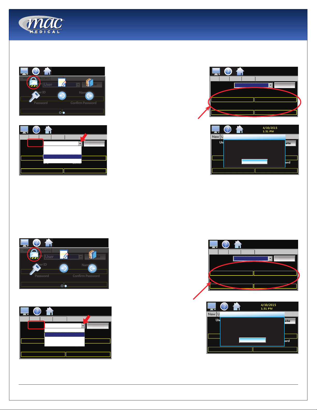
Set up Personal Supervisor Account: After setting up the default supervisor account and logging in, next set up
a personal supervisor account from which you can then create user accounts.
4/10/2015
1:51 PM
New
Users
User Type
Configure Audit User
Password Confirm Password
Password Login Log Off
Access
User ID
Options
User
Fig. 14: Press Congure Icon
4/10/2015
1:51 PM
New
Users
User Type
User ID
Password Confirm Password
Options
Access
SUPERVISOR
User
USER
SYSTEM
USER
SUPERVISOR
ADMINISTRATOR
Create
Name
Create
Name
7. Press the HOME icon to return to
the Home screen. Press MONITOR
icon, then press CONFIGURE icon
(Fig. 14).
8. Select Supervisor from the User
Type drop-down list (Fig. 15).
9. Press the USER ID, NAME, and
PASSWORD boxes to bring up the
keyboard for each category and
enter the relevant information. After
entering each category, hit DONE
in the lower right hand corner on
the keyboard. When nished, press
CREATE (Fig. 16).
4/10/2015
1:51 PM
New
Users
User Type
User ID
MRENALDO
Password Confirm Password
Options
Access
SUPERVISOR
Create
Name
MARK_RENALDO
***** *****
Fig. 16: Set up New Supervisor Account
New User Created.
OK
10. New User Created screen appears.
Fig. 15: Select Supervisor
Press OK (Fig. 17). NOTE: After
setting up the personal supervisor
Fig. 17: New User Created Conrmation
account, use this as a personal
login from this point on.
Create User Account: Set up non-supervisory user accounts, which uses the same procedure as for a supervisor
account.
User Security Levels - You can enter up to 30 users, each with unique ID, full name and password. There are 4
user levels-- Administrator, Supervisor, Systems and User.
4/10/2015
1:51 PM
New
Users
User Type
Configure Audit User
User ID
Password Confirm Password
Password Login Log Off
Access
User
Options
Create
Name
Fig. 18: Press Congure Icon
4/10/2015
1:51 PM
New
Users
User Type
User ID
Password Confirm Password
Options
Access
USER
User
SYSTEM
USER
SUPERVISOR
ADMINISTRATOR
Name
Fig. 19: Select User from Drop Down List
Create
11. Press HOME-MONITOR Icons,
then swipe screen to arrive at
the CONFIGURE icon and press
CONFIGURE (Fig. 18).
12. Select USER from USER TYPE
drop-down menu (Fig. 19).
13. Press the USER ID, NAME, and
PASSWORD boxes to bring
up the keyboard for each
category and enter the
relevant information. After
entering each category, hit
DONE in the lower right hand
corner on the keyboard. When
nished, press CREATE (Fig. 20).
14. When a new USER is created,
a pop-up conrmation will
appear “New User Created”.
Press OK. (Fig. 21)
4/10/2015
1:51 PM
New
Users
User Type
User ID
Password Confirm Password
Access
User
Options
Create
Name
Fig. 20: Enter User ID and Password Info
New User Created.
OK
Fig. 21: New User Created Conrmation
MAN-022
17
www.macmedical.com
Instruction Manual
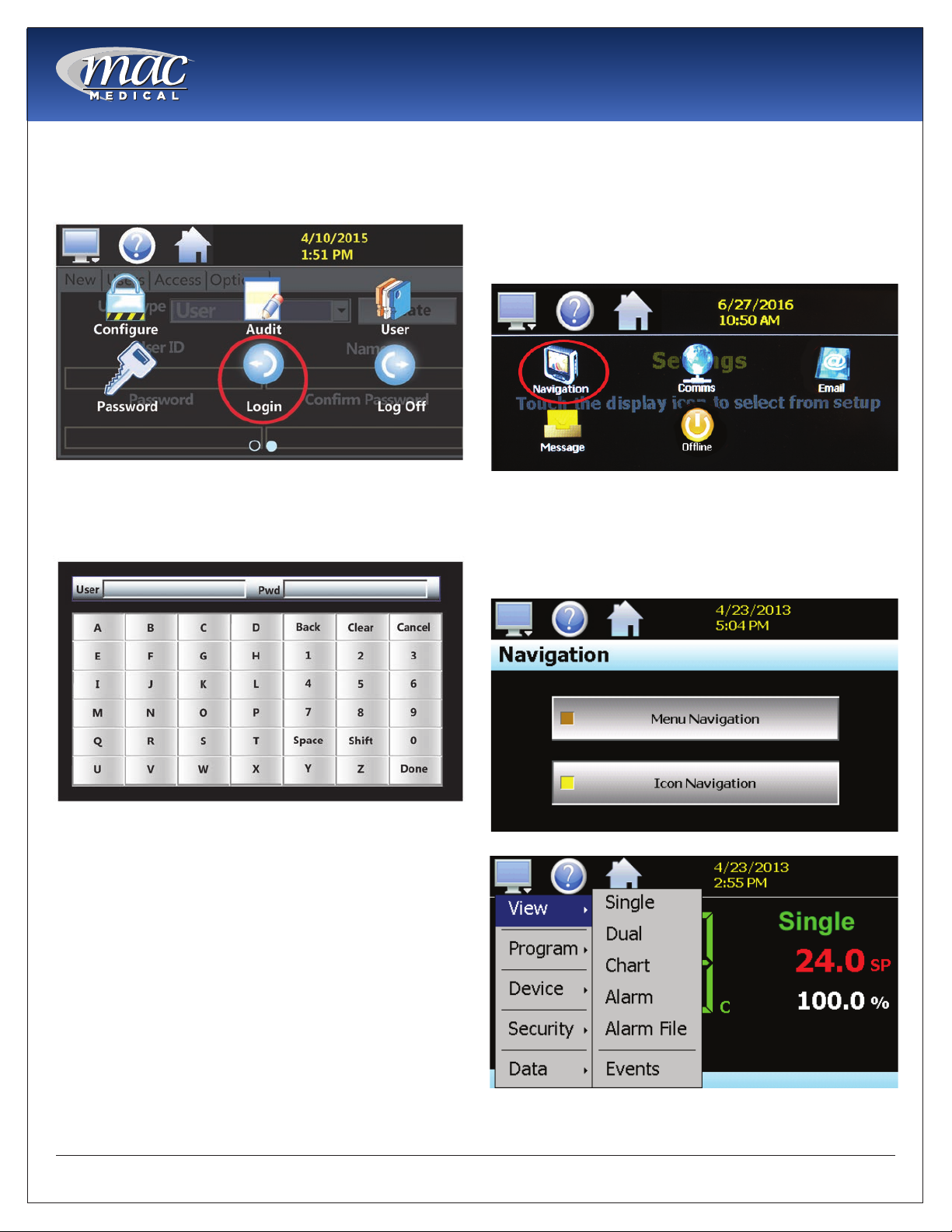
User Login/Log Off
1. To log in, select HOME - MONITOR (swipe screen
left to right) - LOGIN icons (Fig. 22).
Fig. 22: Login Icon
2. Use the pop-up Keyboard to log in (Fig. 23). Tap
on the User eld to enter the user name. Tap on
the Pwd eld to enter the user password.
Navigation
The Touch Screen provides both text based PC
style menus (Fig. 26) and icon based/slide page
navigation menus. The user can select either type at
any time from the Navigation screen.
1. Select HOME - MONITOR - SETTINGS - NAVIGATION
icons (Fig. 24).
Fig. 24: Navigation Icon
2. Select the button for the desired menu type (Fig.
25). When one selection is made, the other will be
de-selected. The button indicator for the active
selection illuminates to show the current selection.
Fig. 23: Keyboard
3. To log off, select HOME - MONITOR (swipe screen
left to right) - LOG OFF icon (Fig. 22). A pop-up
will ask if you want to log off. Select YES to log off,
or NO to abort the log off.
Note: The user may be limited in what applications
he has access rights to as dened by the system
administrator.
Note: Specic Administrator Only tasks are agged
(Admin Only Task) throughout the programming
section of this manual.
MAN-022
Fig. 25: Navigation Screen
Fig. 26: Navigation PC style Menu
18
www.macmedical.com
Advanced Touch Screen Programming
User Accounts (Admin Task)
An Administrator will have access to view all user
accounts, but will not have the ability to view their
passwords. An Administrator can delete a user
account and also change the users passwords.
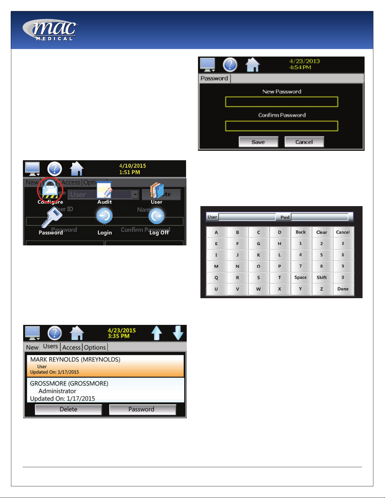
Change User Password
1. To change a user password, select the
HOME - MONITOR - (swipe screen left to right)
-CONFIGURE icons (Fig. 27). When the keyboard
pops up (Fig. 30), log in.
Instruction Manual
Fig. 29: Password Screen - Change User Password
5. Use the pop-up Keyboard to enter a new
password in the yellow box. Re-enter the new
password In the“Conrm Password” yellow box.
Select the DONE button in the lower right corner of
the Keyboard when nished.
Fig. 27: Congure Icon
2. At the CONFIGURE screen (Fig. 28), select the
USERS tab to view information on every user
entered into the system. Use the blue up and
down arrows in the upper right hand corner to
scroll through the list.
3. Select a user from the list (it becomes highlighted)
and press PASSWORD on the bottom of the
screen.
Fig. 28: View Users Screen
Fig. 30: Keyboard
6. When done, press the SAVE button on the
PASSWORD screen.
7. To delete a user, select the user from the list and
press the DELETE button on the bottom of the
USERS screen.
4. At the Password screen (Fig. 29), tap inside the
yellow box “New Password”.
MAN-022
19
www.macmedical.com
Instruction Manual
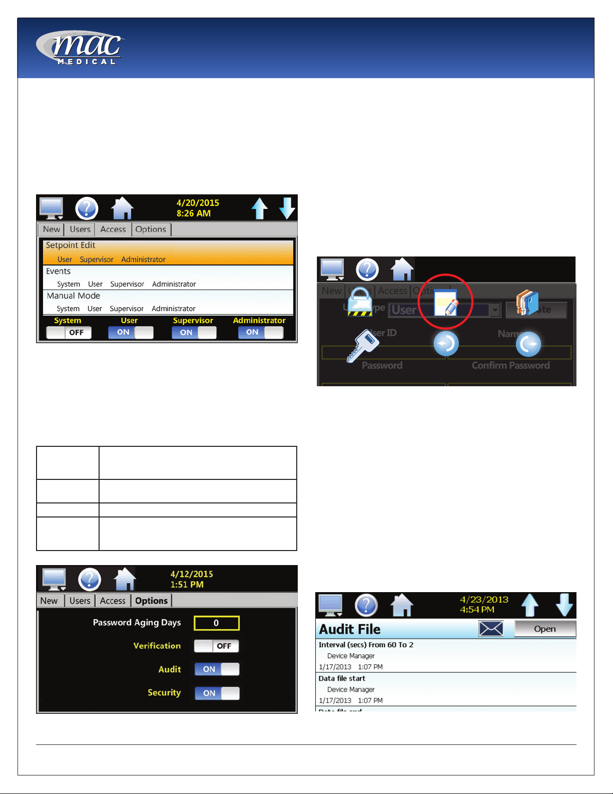
Setting User Access (Admin Task)
The ACCESS tab on the CONFIGURE screen allows an
administrator to assign user permissions.
1. Select the permission from the list. Press the
ON/OFF buttons at the bottom of the screen to
enable or disable the permission for a user level.
(See “Appendix A - System Security User Access
List” for available user access rights.)
Fig. 31: Set User Access
Set Password Aging (Admin Task)
The OPTIONS tab on the CONFIGURE screen (Fig. 31) is
for setting Password Aging Days. This is a global eld
for all users. The aging value starts the day the user is
entered into the system. Set the values and options
below as needed.
Password
Aging Days
Verication When enabled, Verication requires a second
Audit A global setting that turns the audit trail on or off.
Security A global setting that turns the security on or off.
The numeric value can be between 0 and 365
days. Entering 0 into the eld disables password
aging.
log in before the process value be changed.
The Security setting must be enabled in order to
enable the audit trail.
Audit T rail
The AUDIT function displays all user actions affecting
the system for any given day. The Touch Screen
controller can store daily audit les for a period of
a year or longer (time based on storage usage for
data history). Each time a user takes an action that
affects the operation of the system (changing a set
point, start/stop data logging, changes an alarm set
point, etc.), the action is written to a le. NOTE: If no
actions occurred on a given day, an audit le will not
be created for that day.
1. To access Audit les, select HOME - MONITOR -
(swipe screen) AUDIT icons (Fig. 33).
4/10/2015
1:51 PM
New
Users
Access
User Type
Configure Audit User
User ID
Password Confirm Password
Password Login Log Off
Fig. 33: Audit Icon
2. At the Audit File screen (Fig. 34), press the OPEN
button, select a le (Audit le names are listed as
month_day_year), press Open.
Actions recorded to the le includes the date/time
occurence and the user (if logged in) who made
the change. If no user is logged in, the default user is
“Device Manager”.
The E-mail icon allows the user to send a copy of the
currently opened audit trail le to any user congured
in the controller.
3. Press the E-mail icon. An “Add Recipients” window
will display. Select recipients for the le from the
e-mail addresses congured under the controller
e-mail settings.
User
Options
Create
Name
Fig. 32: Set Password Aging Security Option
MAN-022
Fig. 34: Audit Screen
20
www.macmedical.com
Instruction Manual
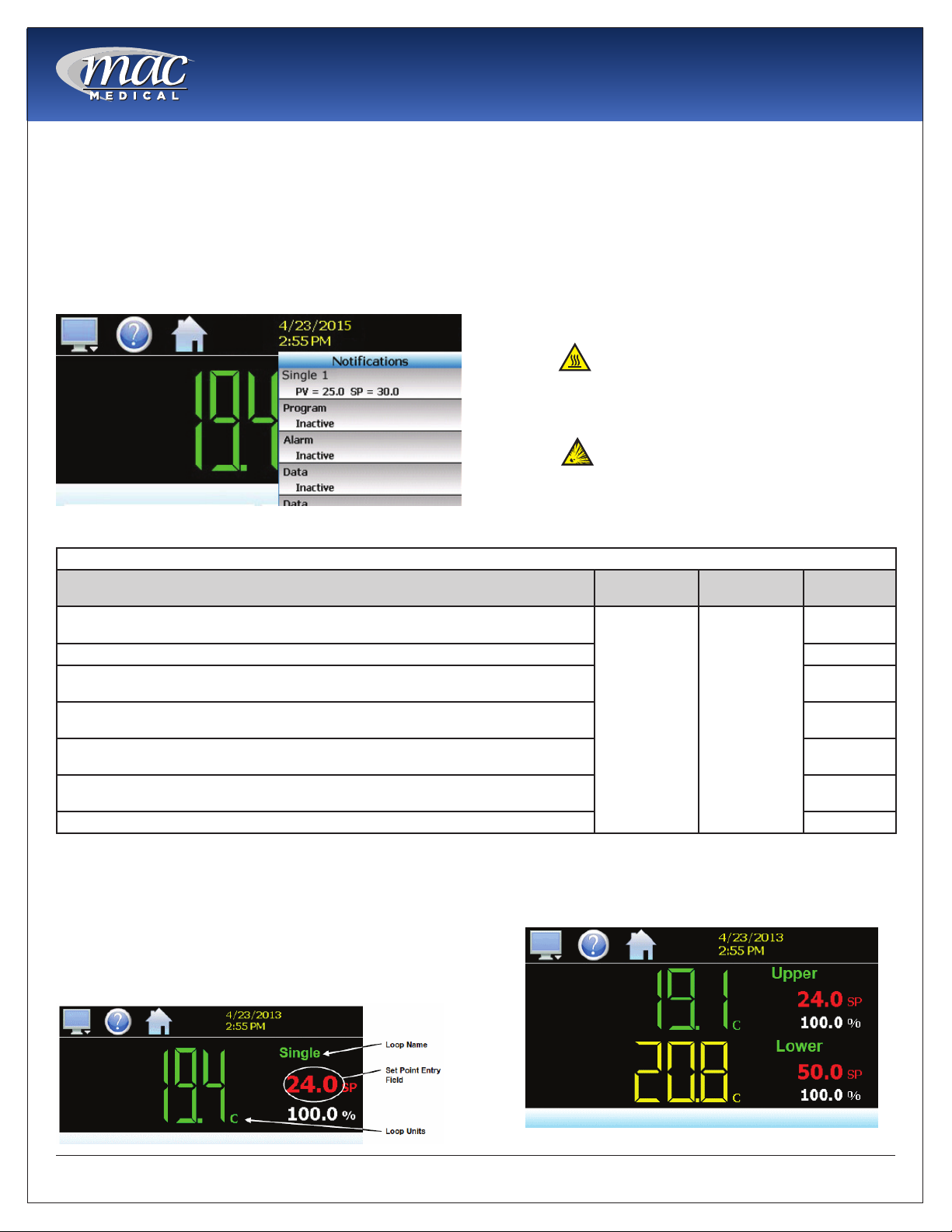
Notications
Current settings, operational conditions and the
current logged in user can be quickly viewed.
1. Press the yellow time/date at the top of the
screen. A drop-down list (Fig. 35) appears listing
the current status of various functions. Swipe the
list to view the whole list. Press the yellow time/
date again to close the list.
Maximum/Minimum Limits Temperature Set Points
Temperature settings may be changed at any time.
The alarm will activate if the setpoint is changed
more than 10° below the actual temperature. See
the Maximum/Minimum Limits Temperature Set Points
table below for various warming cabinets.
Note: If the alarm is activated under normal
operating conditions, turn off power to specic
chamber and call your Mac Medical representative
at 1-877-828-9975.
Caution
Burn Hazard: DO NOT raise the setpoint
temperature to increase the rate of heating. This
could overheat the contents leading to possible
patient burns.
Warning
Explosion Hazard: DO NOT exceed
150° for non-vented closures (screw caps, crimp
seals, plastic pouches, etc. DO NOT exceed
Fig. 35: Notication List
pre-sterile solution manufacturer’s temperature
requirements.
Maximum/Minimum Limits Temperature Set Points and Temperature Tolerances on Warming Cabinet Units
Warmer Cabinet Model Max Temp
Single chamber units SWC182424-TS, SWC183024-TS, SWC182464-TS, SWC243024-TS,
SWC242424-TS
Single chamber unit SWC183036-TS, SWC243036-TS ±2°F
Single chamber unit SWC182474-TS, SWC183064-TS, SWC183074-TS, SWC242464-TS,
SWC242474-TS, SWC243064-TS, SWC243074-TS
Dual Chamber units (Upper Chamber) DWC182464T-TS, DWC183064T-TS, DWC182474T-
TS, DWC183074T-TS, DWC242474T-TS, DWC243074T-TS
Dual Chamber Units (Upper Chamber) DWC183064T, DWC183074E-TS, DWC243064T-TS,
DWC243074E-TS, DWC242464T-TS
Dual Chamber units (Lower Chamber) DWC182464T-TS, DWC183064T-TS, DWC182474T-
TS, DWC183074T-TS, DWC183074E -TS, DWC242464T-TS, DWC243064T-TS, DWC243074E-TS
Dual Chamber units (Lower Chamber) DWC242474T-TS, DWC243074T-TS ±3°F
Set Point
160°F (71°C) 90°F (32°C)
Min Temp
Set Point
Temperature
Tolerance
±1°F
±3°F
±1°F
±2°F
±2°F
Single and Dual Chamber Temperature Setting
The HOME screen shows the current temperature
(in Fahrenheit or Celsius), its data loop (in green) its
setpoint (in red), and percentage of output (in white)
to attain or maintain the temperature.
For single chamber units, the temperature loop name
is called “Single” (Fig. 36).
Fig. 36: Single Chamber Temperature and Setpoint Screen
MAN-022
For dual units, “UPPER” and “LOWER” identify the
temperature loop settings for upper and lower
chambers (Fig. 37).
Fig. 37: Dual Chamber Temperatures and Set Points
21
www.macmedical.com
Instruction Manual
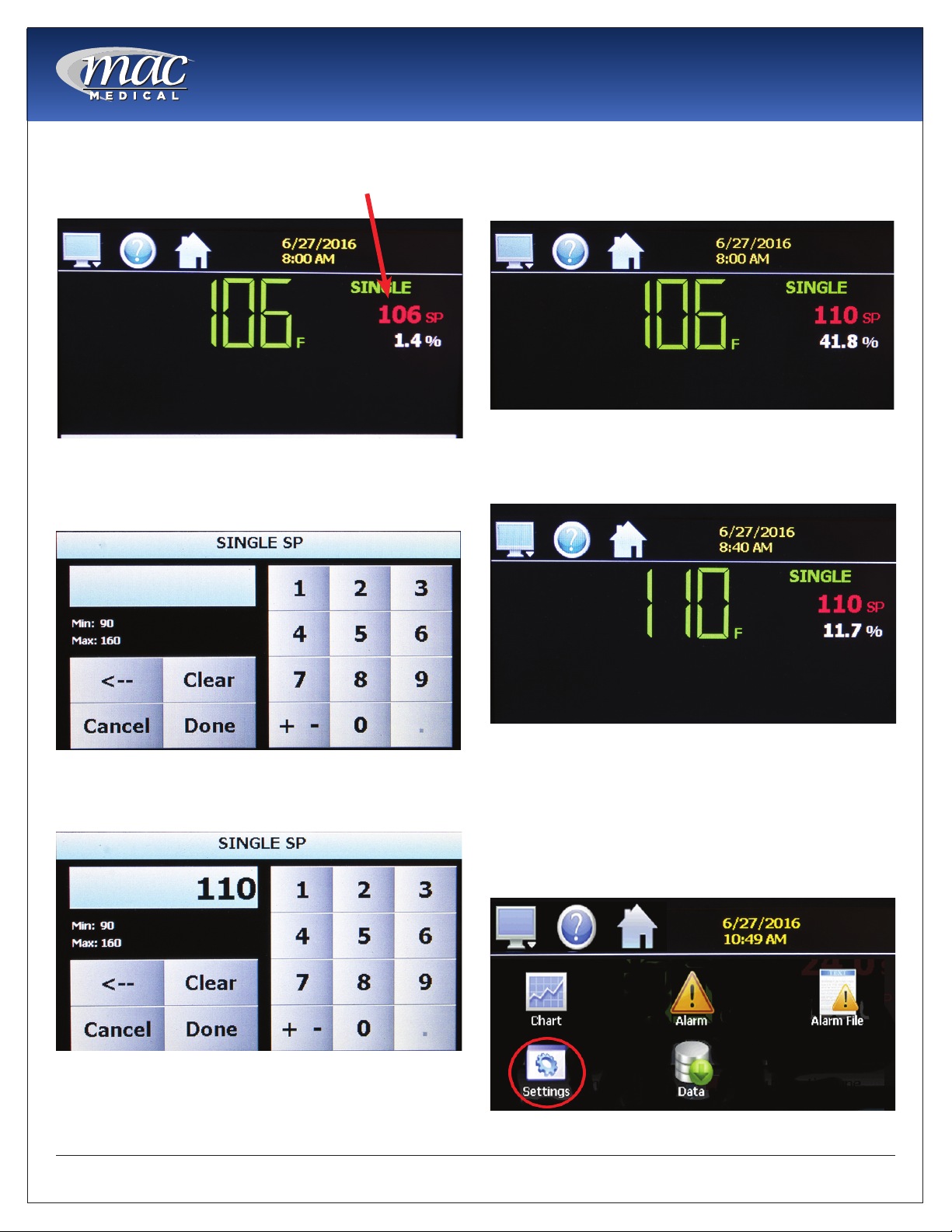
1. To change the chamber setpoint temperature,
from the HOME screen press on the red setpoint
letters of the temperature loop (Fig. 38).
Fig. 38: Single Chamber set at 106 degrees
2. A keypad appears (Fig. 39). The Minimum/
Maximum limits for temperature settings is shown
on the left center.
5. Note the percent of output reading has
changed (Fig. 41). This number will decrease as
the chamber adjusts its temperature to its new
setpoint temperature.
Fig. 41: Set Point Changes to 110 degrees
6. After a period of time, the HOME screen shows
that the chamber temperature has reached its
new temperature setpoint (Fig. 42).
Fig. 39: Set Point Change Screen
3. Using the keypad, input the new set point and
press DONE when nished (Fig. 40).
Fig. 40: Input New Settings
4. The new set point shows on the HOME screen
(Fig. 41).
MAN-022
Fig. 42: Chamber Temperature at New Setting
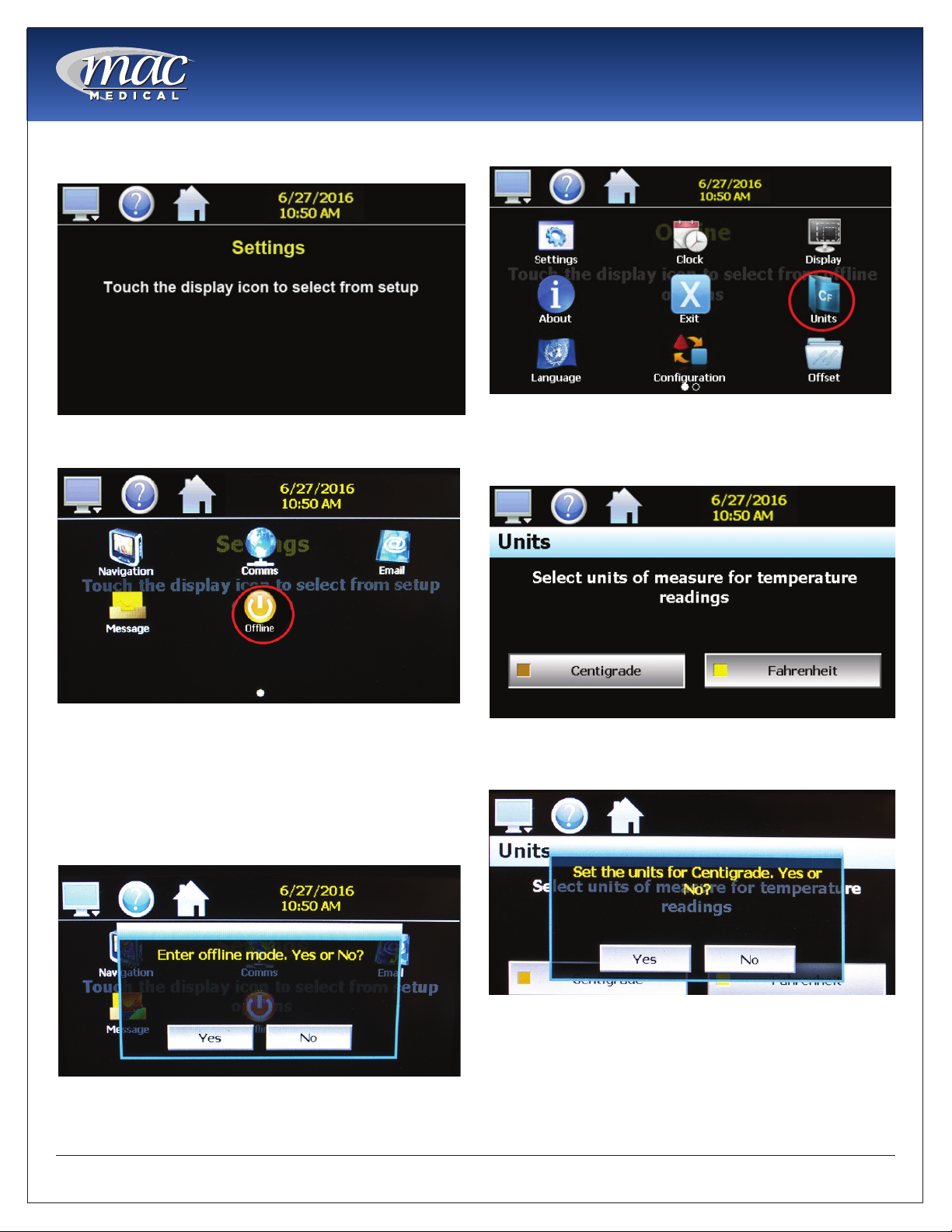
Switching Temperature Units (Admin T ask)
1. This setting is performed only by the Supervisor
or Administrator. If Data Logging is turned on, it
must be turned off in order to switch Fahrenheit/
Celsius temperature units.
2. Select HOME - MONITOR - (swipe screen)
SETTINGS icon (Fig. 43).
Fig. 43: Settings Icon
22
www.macmedical.com
Instruction Manual
3. At the next screen, select MONITOR (display) icon
(Fig. 44).
Fig. 44: Select Monitor (Display) Icon
4. Select OFFLINE icon (Fig. 45).
7. Select UNITS icon (Fig. 47).
Fig. 47: Select Units Icon
8. The temperature unit with a yellow box in its
button is the currently active unit. To change the
unit, select the desired unit (Fig. 48)
Fig. 45: OFFLINE Icon
5. Select YES to enter OFFLINE mode (Fig. 46).
6. At the next screen “OFFLINE Touch the display
icon from setup”(Fig. 44) select the MONITOR
(display) icon.
Fig. 46: Enter Ofine Yes/No
Fig. 48: Select Temperature Unit
9. After selecting the desired temperature unit,
select YES to accept (Fig. 49).
Fig. 49: Set Unit Yes/No
10. The Touch screen controller will automatically
calculate to convert to either Fahrenheit or
Celsius. The HOME screen will thereafter show
the chamber temperature in the converted
temperature unit
MAN-022
23
www.macmedical.com
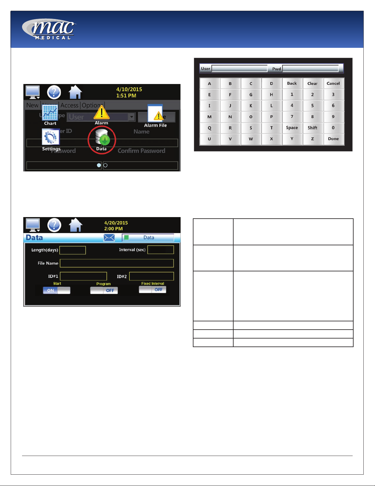
Data File Naming
1. Select HOME - MONITOR (swipe screen left to
right) - DATA icons (Fig. 50).
Instruction Manual
Fig. 52: Keyboard
Fig. 50: Data Icon
2. At the DATA screen (Fig. 51), the green box inside
the “DATA” button is dark green (OFF). The OFF
position allows you to make entries on the DATA
screen.
Fig. 51: Data Screen
3. Tap the box named FILE NAME. A pop-up
keyboard will appear (Fig. 52).
4. Using the keyboard, enter the FILE NAME in the
appropriate box on the DATA Screen. File name
length can be up to 16 characters long. Your le
will save as Filename_mm_dd_yyyy_hh_mm_ss
5. Tap on DONE when nished.
Data Logging
The Touch Screen controller logs data to its SD card.
Current data for each variable is written to the log at
a xed interval based on the settings entered in the
Length and Interval elds. The table below lists and
describes the Data screen variables.
LENGTH OF
DAYS
INTERVAL
(Sec)
FIXED
INTERVAL
ID#1 and ID#2 Allows more specic identication of the le.
START Automatically turns on data logging.
PROGRAM Should be kept OFF.
1. After creating a le name in the DATA, touch the
LENGTH (days) box. Enter the number of days
(1 to 31) the data will be logged on the pop-up
Interval Keypad (Fig. 52).
Sets a data le length in number of days (from 1
to 31 days). Once the selected number of days
has elapsed, a new data le will be created
and logging will continue in the new le.
The number of seconds the data to be logged.
The Interval can be manually set from 2 to 1860
seconds. To do this, toggle OFF“Fixed Interval”
and enter the desired logging rate in seconds.
When toggled ON, the logging interval will be
automatically set to record at minute intervals
based on the number of days set for the le. If
the le is set for 1 day in length, the logging
rate will be at 1 minute intervals. If the le is set
for 7 days, then the logging rate will be every 7
minutes. The “Fixed Interval” keeps the le size
manageable.
MAN-022
24
www.macmedical.com