

Ohio 7300 Installation and user manual
Schaerer Medical USA, Inc.
Go To Table Of Contents
Important
Information
Page 2
Installation
Installation and Operation
Manual
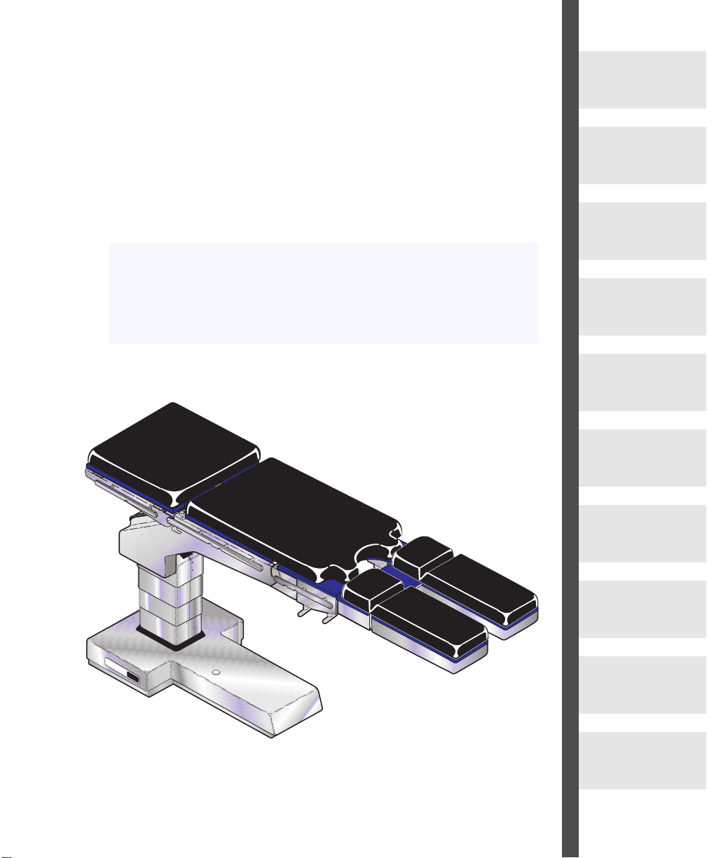
Model 7300 Modular
Surgery Table
Page 4
Description
Page 7
Components
Overview
Page 8
Controls &
Indicators
Page 9
Operation
Page 12
Operator
Maintenance
Page 25
OMI
7300
CA802000
Calling For
Service
Page 26
Specifications &
Accessories
Page 26
Limited
Warranty
Page 31
MODEL
NUMBER
SERIAL
NUMBER
OMI
7100-001
115 VAC
2 AMP 60 HZ
TDWXXXXX
MODEL
INPUT
RATING
SERIAL NO.
Owner’s Product Identification
Go To Table Of Contents
(information that you will need to provide for servicing - key information is highlighted)
Date of Purchase Serial Number
Name of Owner / Facility / Department
Model Number
Name of Authorized SM-USA Dealer Telephone # of Authorized SM-USA Dealer
Address of Authorized SM-USA Dealer
OMI
7100
CA7681

CONTENTS
IMPORTANT INFORMATION.................................................................................................2
Scope and Purpose of This Manual ...............................................................................2
Intended Use of Product.................................................................................................2
Safety Instructions ..........................................................................................................2
Explanation of Safety Symbols and Notes......................................................................2
Transportation and Storage Conditions ..........................................................................3
INSTALLATION ......................................................................................................................4
Unpacking.......................................................................................................................4
DESCRIPTION........................................................................................................................7
Introduction.....................................................................................................................7
Features..........................................................................................................................7
COMPONENTS OVERVIEW ..................................................................................................8
CONTROLS & INDICATORS...................................... ...... ....... ...... ....... ...... ...... .....................9
OPERATION............................... ....... ...... ....... ...... ....... ...... ....... ............................................12
Patient Positions & Weight Capacities..........................................................................12
Head Section, Installation & Operation............................................................. ...... ......13
Installing Table Top Sections ........................................................................................13
Possible Pinch Points....................................................................................................14
Pendant Hand Control............................ ................................................... ....... ...... ......16
Foot Control..................................................................................................................18
Emergency Override Panel...........................................................................................20
Hand Control Display Messages ..................................................................................22
OPERATOR MAINTENANCE ..............................................................................................25
Preventive Maintenance Schedule ...............................................................................25
Cleaning .......................................................................................................................25
CALLING FOR SERVICE.....................................................................................................26
SPECIFICATIONS & ACCESSORIES .............................................................. ....... ...... ......26
Options and Accessori es........................................... ....... ...... ....... ...... ...... ....... ...... ......27
LIMITED WARRANTY..........................................................................................................31
Return To Table Of Contents
RETURN TO TABLE
OF CONTENTS
Important
Information
IMPORTANT INFORMATION
Scope and Purpose of This Man ual
This manual covers complete instructions for the installation, operation, and normal care of the Model 7300 Surgery Table. It is intended that this manual be
used by any medical personnel responsible for operating the surgery table during a medical procedure or performing operator level maintenance.
Intended Use of Product
The intended use of the Model 7300 Surgery Table is to perform general surgical procedures.
Safety Instructions
The primary concern of SM-USA is that this equipment is operated and maintained with the safety of the patient and staff in mind. T o assure safer and more
reliable operation:
• Read and understand this manual before attempting to install or operate the
table.
• Assure that appropriate personnel are informed on the contents of this manual; this is the responsibility of the purchaser.
• Assure that this manual is located near the table, or if possible, permanently
affixed to the table.
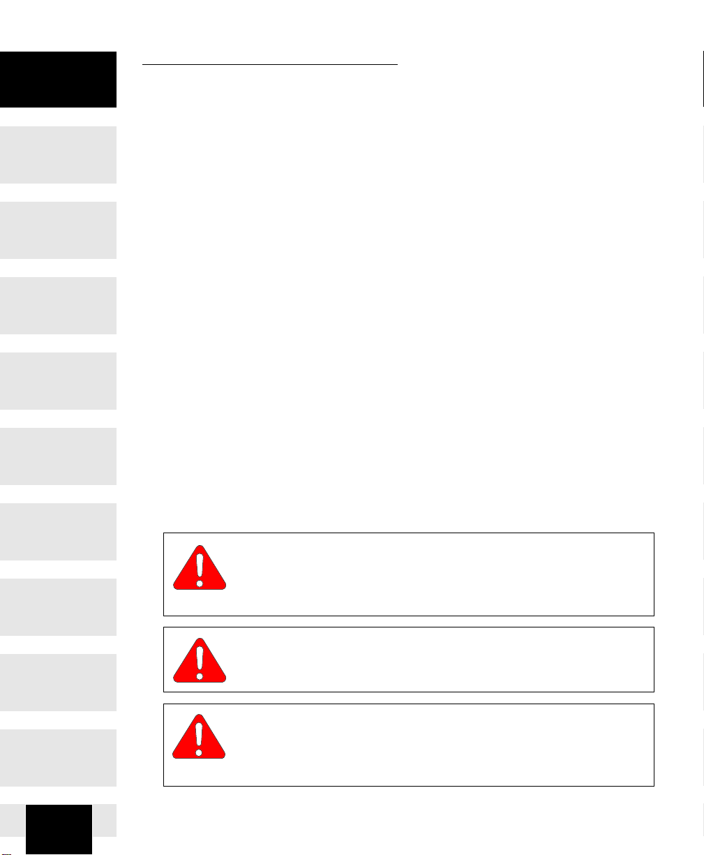
Explanation of Safety Symbols and Notes
symbol is limited to the most extreme situations.
against unsafe practices.
2
DANGER
Indicates an imminently hazardous situation which, if not
avoided, will result in death or serious injury. The DANGER
WARNING
Indicates a potentially hazardous situation which, if not avoided, could result in death or serious injury.
CAUTION
Indicates a potentially hazardous situation which, if not avoided,
may result in minor or moderate injury. It may also be used to alert
Return To Table Of Contents
RETURN TO TABLE
OF CONTENTS
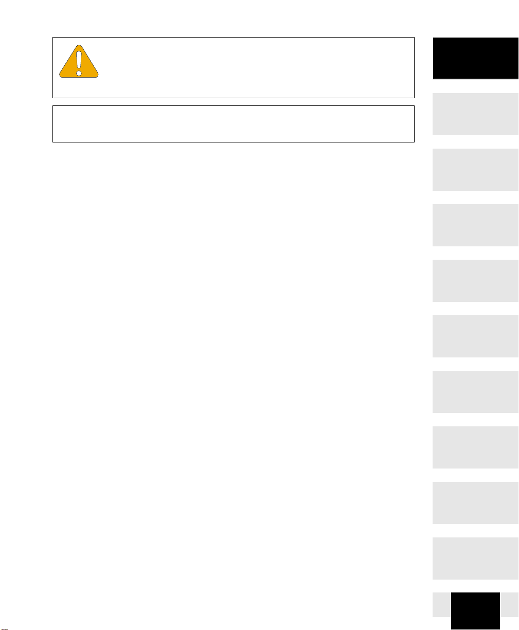
EQUIPMENT ALERT
Indicates an imminently or potentially hazardous situation which, if
not avoided, will or may result in serious, moderate, or minor
equipment damage.
NOTE
Amplifies an operating procedure, practice, or condition.
Transportation and Storage Conditions
• Ambient Temperature Range:..... -20°C to +40°C (-4°F to 104°F)
• Relative Humidity........................ 10% to 90% (non-condensing)
• Atmospheric Pressure ................ 500hPa to 1060hPa (0.49atm to 1.05atm)
Important
Information
3
INSTALLATION
Return To Table Of Contents
Unpacking
RETURN TO TABLE
OF CONTENTS
Installation
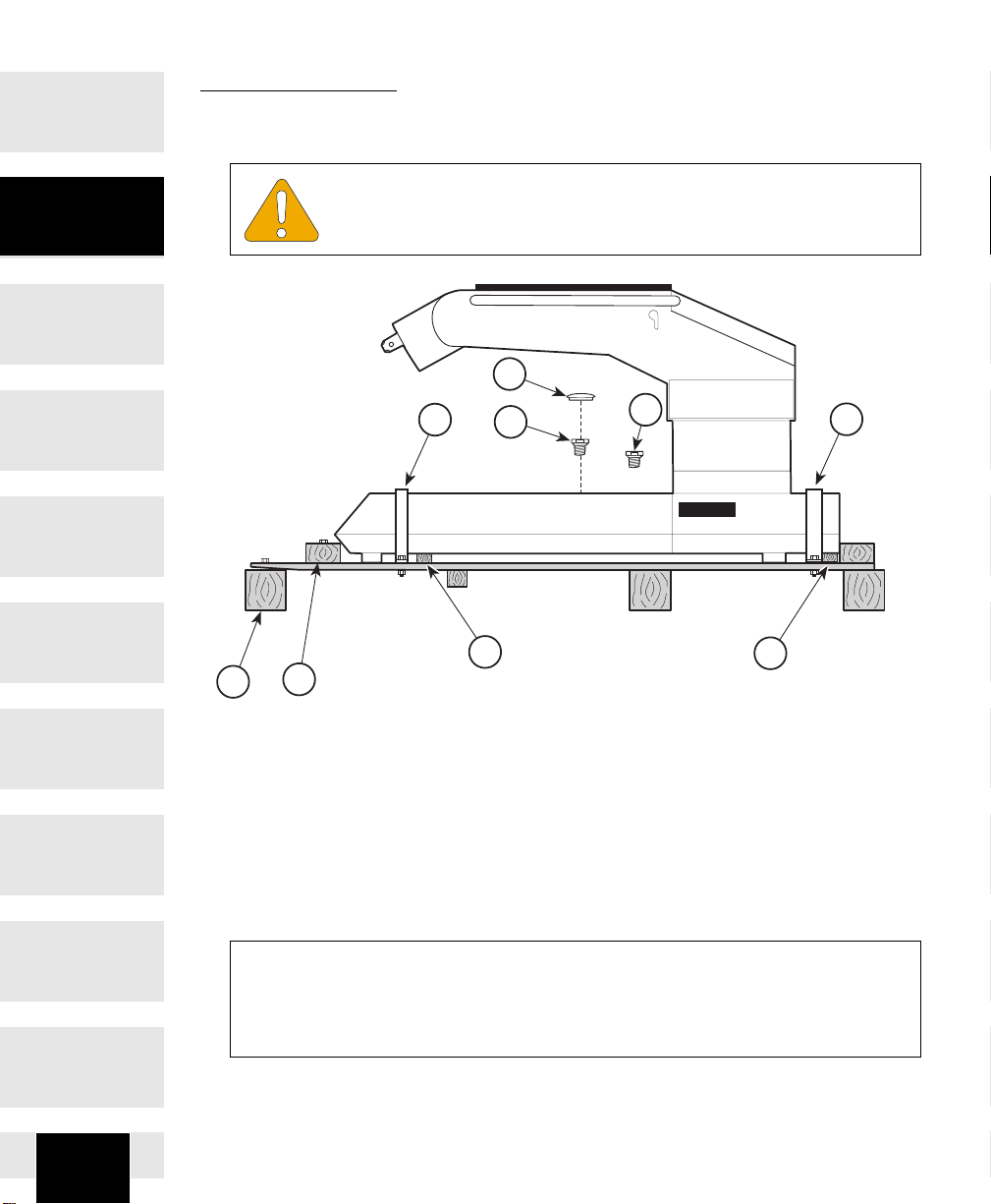
EQUIPMENT ALERT
To avoid damaging the table do not use a knife or other sharp object to open the table’s packaging.
2
1
7
6
3
5
FIGURE 1
4
5
1
CA799300
1. Carefully cut the banding, remove the washer head nails, and lift off the
cardboard shipping box.
2. Remove the plastic bag from around the table and inspect the table for any
shipping damage.
3. Remove the box with accessories, etc. located on the table base and inspect
for shipping damage.
NOTE
You must report any shipping damage to the transit company
of receiving the table from the transit company and ask them for an inspection.
4
within 15 days

HAND CONTROL
FOOT CONTROL
ENABLE
LOCK
Return To Table Of Contents
RETURN TO TABLE
OF CONTENTS
4. Unbolt and remove the two metal straps (1) from around the table base.
EQUIPMENT ALERT
not
Do
from the hydraulic reservoir and the vent plug has been installed in
its place.
5. Remove the shipping plug (2) from the table’s hydraulic fluid reservoir and
install the vent plug (3) in it’s place; then install the hole plug (4).
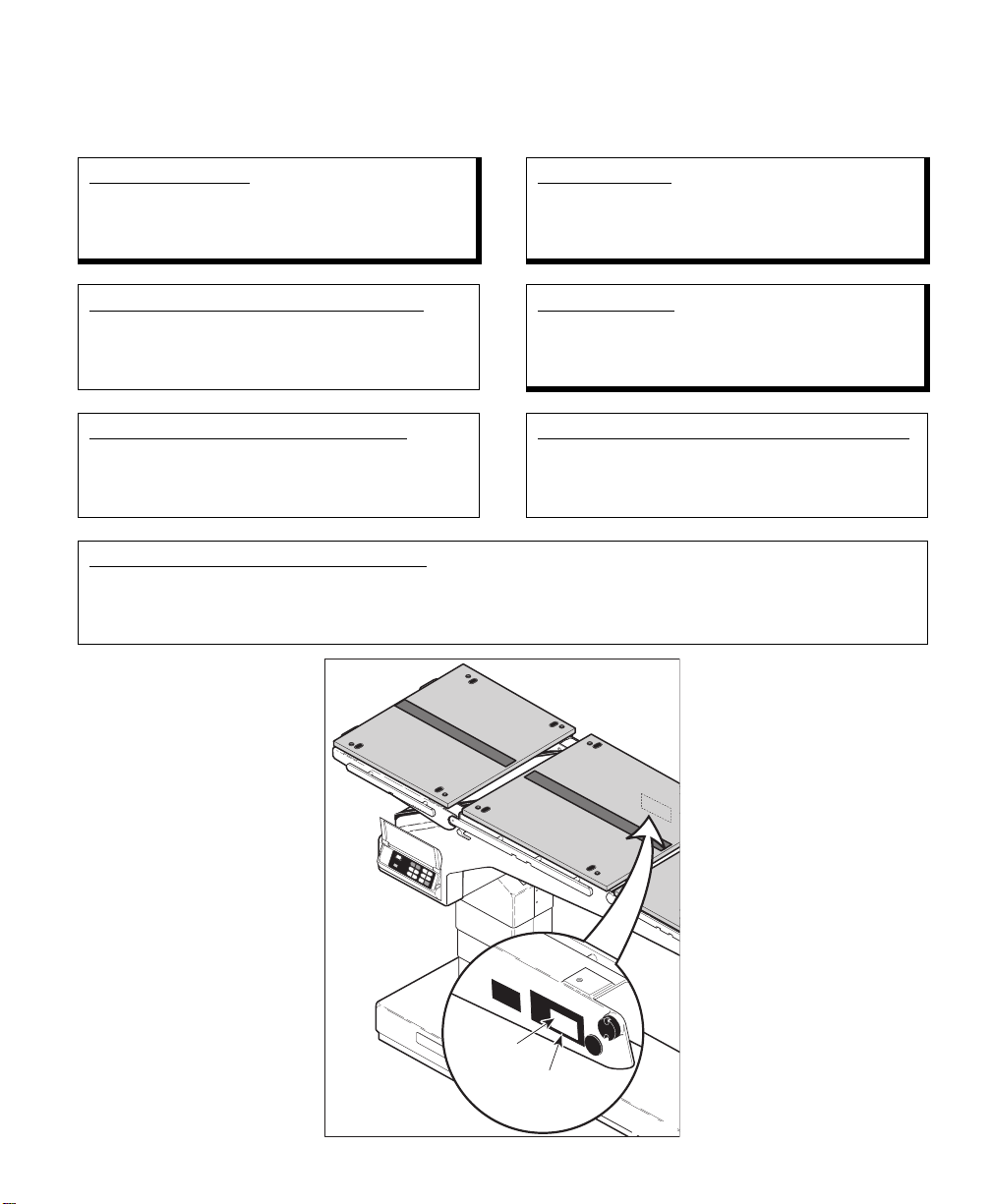
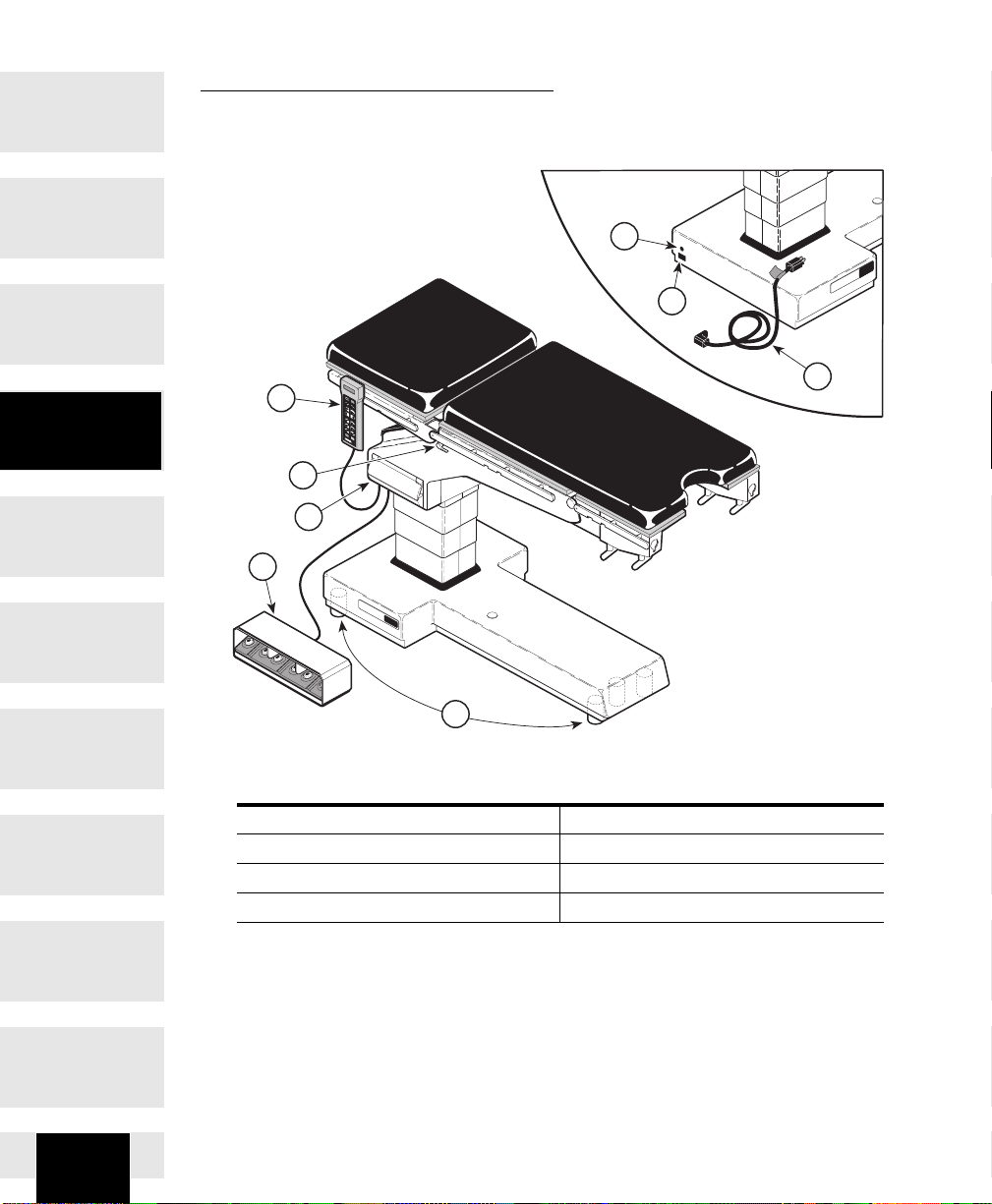
6. Locate the hand control that
has been packaged with the
table and plug the cord of the
hand control into the port
labeled HAND CO NTROL
located on the bottom, patient’s
right side of the table top.
NOTE
If the hand control does not respond when turned on, it may
mean the table’s battery system
needs to be charged. Using the
table’s power cord, connect the
cord to the table and then plug
the cord into a 115 VAC , 60 Hz,
hospital grade power receptacle. Allow the batteries to
charge for 1/2 hour; then remove the power cord and continue with unpacking
procedures.
operate the table until the shipping plug has been removed
ENABLE
LOCK
DISABLE
LEVEL
UNLOCK
MIDOMIARK
7100
7100
CA799400
Installation
7. Press the
N
“
ORMAL POSITION
ENABLE/LOCK
and outriggers will function, locking the table to the skid.
8. Remove the two wood slats (5, Figure 1) from beneath
the table base.
9. Unbolt and remove the wood block (6) at the foot end base of the table.
button. The display should read,
...L
OCKING FLOOR
”.
The floor locks
5

Installation
Return To Table Of Contents
RETURN TO TABLE
OF CONTENTS
10.Unbolt and remove the wood block (7) located at the foot end base beneath
the wood skid.
WARNING
The table w/ Pelvic Base (73001) weighs approximately 660
lbs. (299.4 kg). Get an assistant to help remove the table from
the shipping skid. Also, use proper lifting techniques when lifting table.
Failure to do so could result in serious back injury.
11.Using an assistant, take hold of
each side of the table; then press
E
the
NABLE/LOCK
tons and
floor locks will disengage.
hold for 3 seconds
and
U
NLOCK
but-
. The
ENABLE
UNLOCK
LOCK
EQUIPMENT ALERT
Assure the brake cylinders have retracted all the way before attempting to roll the table from the skid. Failure to comply may
cause damage to the brake cylinders.
12.Carefully roll the table to the foot end of the skid. The skid tilts, allowing the
table to be rolled off.
result in damage to the table.
13.Plug the table into a 115 V AC, 60 Hz, hospital grade, grounded outlet from 8
to 12 hours to fully recharge the batteries before actual use.
table has been exposed to below freezing temperature during transit.
6
EQUIPMENT ALERT
Use only 115 volt, alternating current (VAC), 60 cycle (Hz) to operate or recharge the batteries in the table. Failure to comply could
EQUIPMENT ALERT
To prevent damage to the table, allow the table to reach room temperature before operating. This is especially important when the

Return To Table Of Contents
RETURN TO TABLE
OF CONTENTS
DESCRIPTION
Introduction
The 7300 Modular Surgical Table is primarily used for general surgery but can
be easily adapted with various accessories to accomodate many different procedures such as cardio vascular, neurosurgical, urology, obstetrics, gynecologic, and orthopaedic.
Features
The Model 7300 General Surgical Table has . . .
• excellent image amplification with superior C-arm access.
• excellent access for anesthetist for short patients in lithotomy or other positions.
• a variety of accessories for almost any surgical procedure.
• various accessories constructed of light-weight carbon fiber yet retaining the
strength and durability for optimum life plus providing excellent radio-translucency.
• stainless steel and carbon fiber construction for strength and cleanability.
• five powered functions that include powered floor locking, height adjustment,
lateral tilt, trendelenburg, and seat positioning.
• a “Return to Level” feature that, when enabled, automatically stops each
function at the level or “neutral setting.
• ability to flex and reflex table position with a single button.
• three sources for table positioning commands, pendant hand control,
optional foot control, or the emergency override contr ol.
• back up hydraulic motor/pump in case the primary motor/pump becomes
disabled.
Description
• ability to power the table directly from a 115 V AC power source for limited
periods should the batteries become fully discharged.
• ideal position for lithotomy without compromising other forms of surgery.
• state-of-the-art factory and field, trained, technical service organizations
plus easy- to-follow technical literature,
equipment is maintained at peak operating performance.
in paper or CD format
, to assure your
7
Return To Table Of Contents
RETURN TO TABLE
OF CONTENTS
COMPONENTS OVERVIEW
The illustration below shows the location of the table’s major components and
the chart below provides their descriptive name.
5
6
7300
OMI
Component
Overview
ENABLE
LOCK
1
DISABLE
LEVEL
UNLO
OMI
CK
7100
8
3
2
OMI
7300
4
CA800300
DESCRIPTION OF COMPONENTS (Basic Table)
1. Hand Control 5. Line Power Pilot Lamp
2. Foot Control (Optional) 6. Plug Receptacle
3. Emergency Override Panel 7. Power Cord
4. Floor Lock Cylinders 8. Latch Handle(s)
7
8
Return To Table Of Contents
RETURN TO TABLE
OF CONTENTS
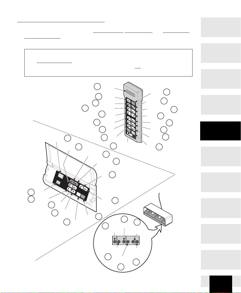
CONTROLS & INDICATORS
The illustration below shows the
override control
. The chart that follows describes the function of each button
hand control,
foot control,
emergency
and
or switch...Refer to “OPERATION” Section on each control before using them.
NOTE
The Reverse Position, patient’s
tivated when us ing the hand co ntrol. R e v ers e Position is not
Emergency Override or Foot Control.
SYSTEM
OVERRIDE
18
TABLE
UP
6
TRENDELENBURG
head at opposite e nd from c olu mn, can only be ac -
avail ab le when us ing the
HAND
CONTROL
1
2
NORMAL
4
POSITION
TRENDELENBURG
6
8
LATERAL
10
TILT LEFT
12
DISPLAY
ENABLE
TABLE
UP
SEAT
UP
14
FLEX
(RETURN TO)
16
LEVEL
ENABLE
LOCK
DISABLE
LEVEL
UNLOCK
OMI
7100
DISABLE
REVERSE
POSITION
TRENDELENBURG
TABLE
DOWN
UNLOCK
REVERSE
9
LATERAL
TILT RIGHT
SEAT
DOWN
REFLEX
17
5
13
3
15
4
REVERSE
TRENDELENBURG
5
7
11
Controls &
Indicators
SYSTEM
OVERRIDE
DISABLE
DISABLE
3
LATERAL
8
TILT LEFT
7
TABLE
DOWN
LATERAL
9
TILT RIGHT
16
LOCK
LEVEL
UNLOCK
UNLOCK
SEAT
10
UP
SEAT
11
DOWN
17
6
TRENDELENBURG
REVERSE
TRENDELENBURG
7
TABLE
DOWN
8
TABLE
UP
9
10
LATERAL
TILT
LEFT
LATERAL
TILT
RIGHT
11
CA799800
9
 Loading...