

Page 1
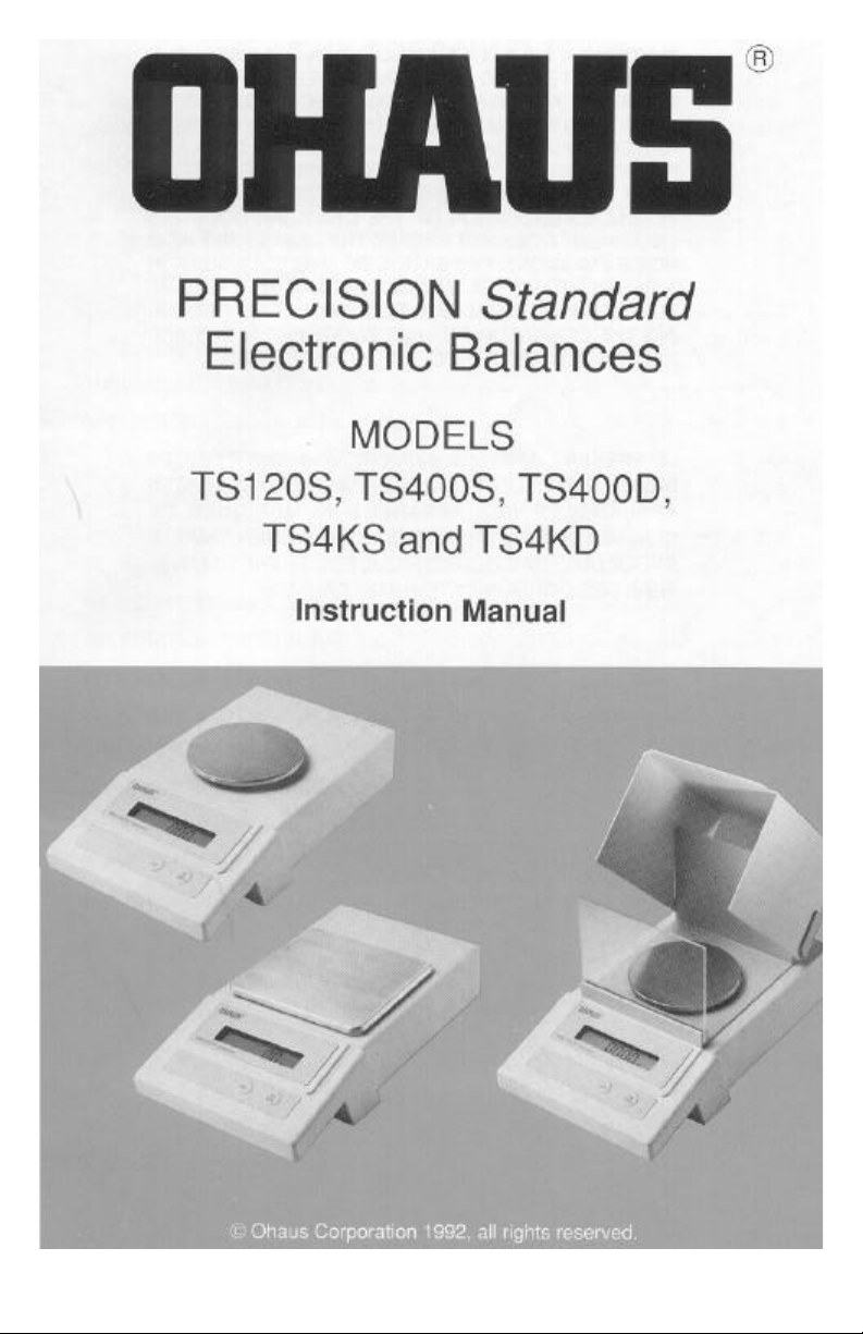
Page 2
Page 3
Page 4
Page 5
Page 6
Page 7
Page 8
Page 9
Page 10
Page 11
Page 12
Page 13
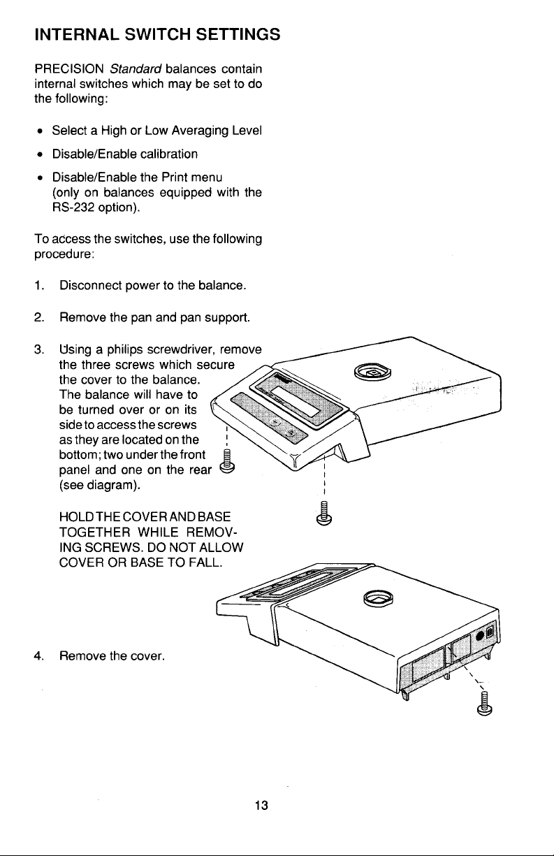
Page 14
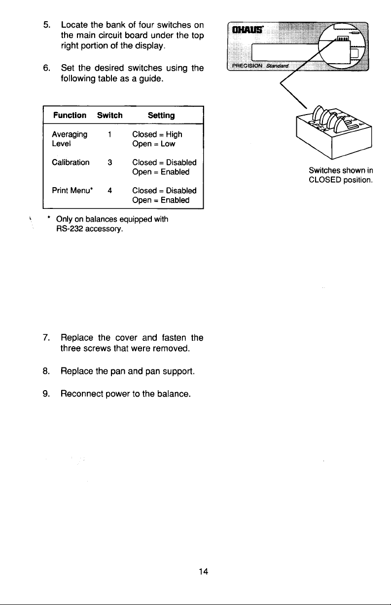
Page 15
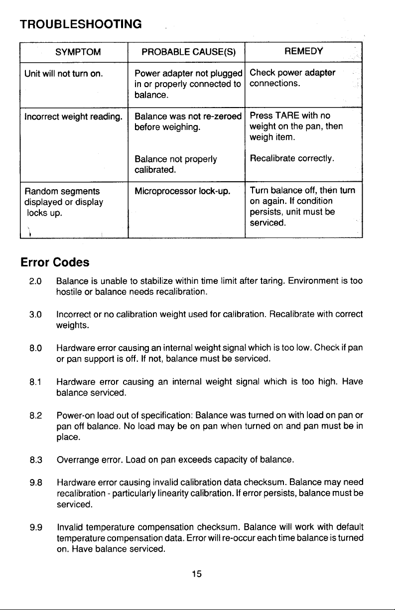
Page 16
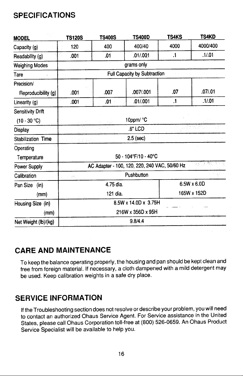
Page 17
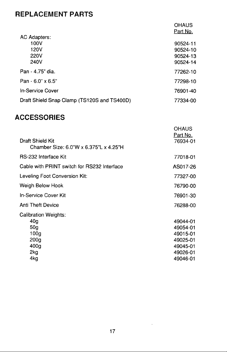
Page 18
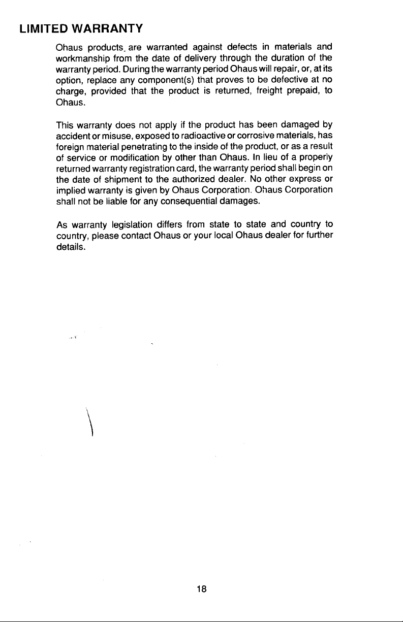
Page 19

Ohaus Corporation
29 Hanover Road
Florham Park NJ
07932-0900
PRECISION
Electronic Balances
TS Series
Standard
Instruction Manual
Page 20

NOTE:NOTE:
NOTE: THIS EQUIPMENT HAS BEEN TESTED AND FOUND TO
NOTE:NOTE:
COMPLY WITH THE LIMITS FOR A CLASS A DIGITAL DEVICE, PURSUANT TO PART 15 OF THE FCC RULES.
THESE LIMITS ARE DESIGNED TO PROVIDE REASONABLE PROTECTION AGAINST HARMFUL INTERFERENCE WHEN THE
EQUIPMENT IS OPERATED IN A COMMERCIAL ENVIRONMENT.
THIS EQUIPMENT GENERATES, USES, AND CAN RADIATE RADIO
FREQUENCY ENERGY AND, IF NOT INSTALLED AND USED IN ACCORDANCE WITH THE INSTRUCTION MANUAL, MAY CAUSE
HARMFUL INTERFERENCE TO RADIO COMMUNICATIONS. OPERATION OF THIS EQUIPMENT IN A RESIDENTIAL AREA IS LIKELY
TO CAUSE HARMFUL INTERFERENCE IN WHICH CASE THE USER
WILL BE REQUIRED TO CORRECT THE INTERFERENCE AT HIS
OWN EXPENSE.
THIS DIGITAL APPARATUS DOES NOT EXCEED THE CLASS A LIMITS FOR RADIO NOISE EMISSIONS FROM DIGITAL APPARATUS AS
SET OUT IN THE INTERFERENCE-CAUSING EQUIPMENT STANDARD ENTITLED “DIGITAL APPARATUS”, ICES-003 OF THE
DEPARTMENT OF COMMUNICATIONS.
CET APPAREIL NUMERIQUE RESPECTE LES LIMITES DE BRUITS
RADIOELECTRIQUES APPLICABLES AUX APPAREILS NUMERIQUES
DE CLASSE A PRESCRITES DANS LA NORME SUR LE MATERIEL
BROUILLEUR : “APPAREILS NUMERIQUES”, NMB-003 EDICTEE PAR
LE MINISTRE DES COMMUNICATIONS.
Unauthorized changes or modifications to this equipment are not
permitted.
2
Page 21

TABLE OF CONTENTSTABLE OF CONTENTS
TABLE OF CONTENTS
TABLE OF CONTENTSTABLE OF CONTENTS
INTRODUCTION .................................................................................................. 5
DESCRIPTION ..................................................................................................... 5
UNPACKING ........................................................................................................ 6
INSTALLATION .................................................................................................... 7
Environment .................................................................................................. 7
Draft Shield ................................................................................................... 7
Pan and Pan Support .................................................................................... 8
AC Adapter.................................................................................................... 8
OPERATION ........................................................................................................ 9
Turning the Balance ON................................................................................ 9
Stabilization ................................................................................................... 9
Auto Range Models....................................................................................... 9
Checking Calibration ................................................................................... 10
Weighing .................................................................................................... 10
Taring .......................................................................................................... 11
USING MENUS TO CONFIGURE THE BALANCE ........................................... 12
CALIBRATION MENU ........................................................................................ 13
Calibration Menu Protection ........................................................................ 13
Calibration Weights ..................................................................................... 13
Span Calibration.......................................................................................... 14
Linearity Calibration .................................................................................... 15
End .............................................................................................................. 16
USER MENU ...................................................................................................... 17
User Menu Protection ................................................................................. 17
Reset to Factory Defaults............................................................................ 18
Averaging Level .......................................................................................... 19
Stability Range ............................................................................................ 20
Auto-Zero .................................................................................................... 20
End .............................................................................................................. 21
3
Page 22

SETUP MENU .................................................................................................... 22
Setup Menu Protection................................................................................ 22
Unit Selection .............................................................................................. 23
Lock Switch ................................................................................................. 24
End .............................................................................................................. 25
MENU LOCK-OUT PROTECTION..................................................................... 25
CARE AND MAINTENANCE.............................................................................. 26
TROUBLESHOOTING ....................................................................................... 26
Error Codes................................................................................................. 27
SERVICE INFORMATION ................................................................................. 28
SPECIFICATIONS ............................................................................................. 29
PARTS INFORMATION ..................................................................................... 30
REPLACEMENT PARTS ................................................................................... 30
ACCESSORIES ................................................................................................. 30
LIMITED WARRANTY........................................................................................ 31
4
Page 23
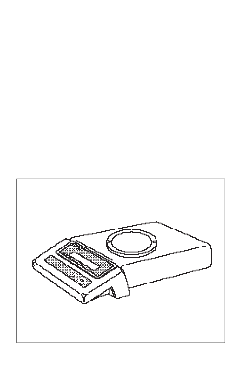
INTRODUCTION
This manual covers installation, operation and troubleshooting for the Ohaus Precision
Standard balances, Models TS120, TS200, TS400, TS400D, TS600, TS2K, TS4K and
TS4KD. To insure proper operation of the balance, please read this manual completely.
DESCRIPTIONDESCRIPTION
DESCRIPTION
DESCRIPTIONDESCRIPTION
The Ohaus Precision Standard series balances are precision weighing instruments,
designed to provide years of service with virtually no maintenance. The Precision
Standard series is constructed using a die-cast aluminum base finished with a durable
epoxy powder paint which is resistant to commonly used acids, contains a one piece
solid-state precision electronics PC board, a seven digit LCD display which is 0.6 inches
in height. All Precision Standard series balances are factory set to measure in grams.
Each balance operates through a series of menus which enable precise calibration and
linearity along with various other parameters which enhances operation. A built in lock
switch prevents preset settings from being changed. To prevent measurements from
being affected by air currents, a draft shield is used on Models TS120, TS200 and
TS400D balances. Power is supplied through an AC adapter which is available in five
voltages for world-wide usage. Accessories include: an RS232 interface kit which
allows printing of results through an external computer, an RS232 Interface cable with
a print switch, weigh below hook, security device and calibration weights.
PRECISION
Standard
5
Balance
Page 24
UNPACKINGUNPACKING
UNPACKING
UNPACKINGUNPACKING
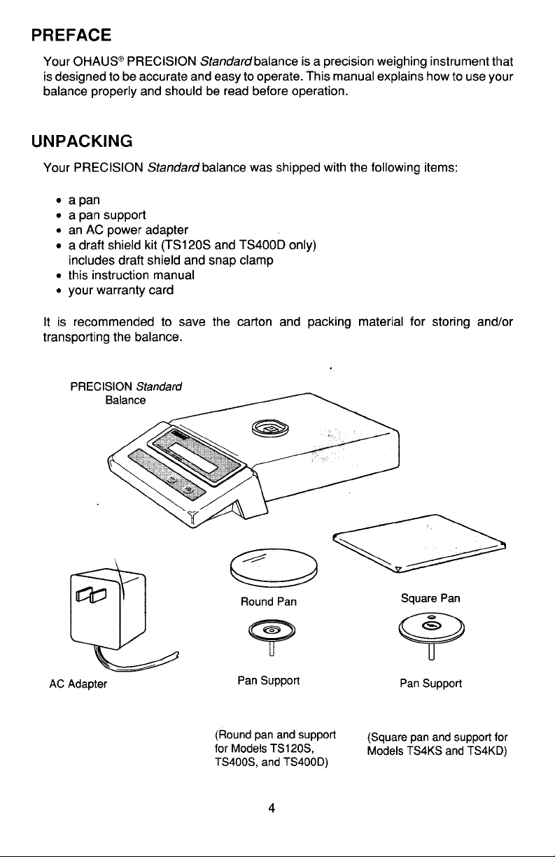
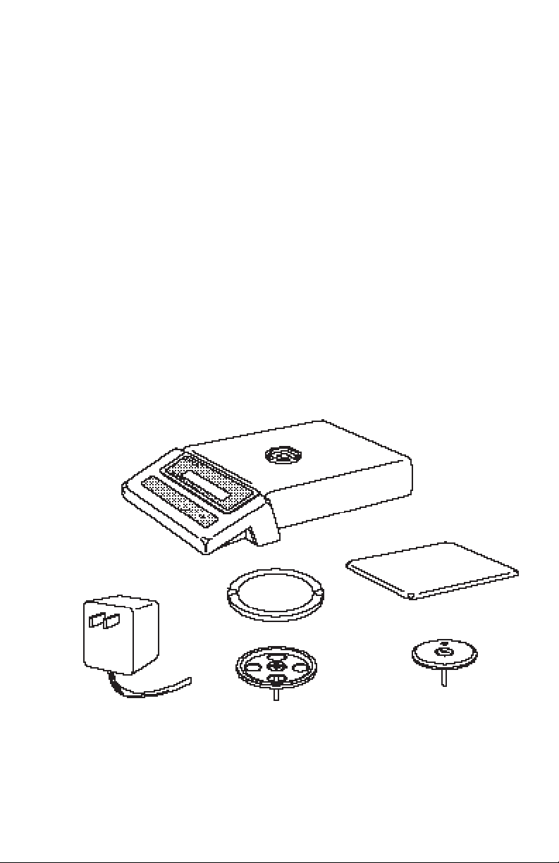
Your Precision Standard balance was shipped with the following items:
• a pan
• a pan support
• an AC power adapter
• a draft shield (TS120, TS200 and TS400D only)
includes draft shield and snap clamp
• this instruction manual
• your warranty card
It is recommended to save the carton and packing material for storing , transporting the
balance or returning it for service.
Precision Standard
Balance
Round Pan
(Round pan and support
for Models TS120,
TS200, TS400, TS600,
and TS400D)
6
Square Pan
Pan SupportAC Adapter Pan Support
(Square pan and support for
Models TS2K, TS4K and
TS4KD)
Page 25
INSTALLATIONINSTALLATION
INSTALLATION
INSTALLATIONINSTALLATION
EnvironmentEnvironment
Environment
EnvironmentEnvironment
The balance should always be used in an environment which is free from excessive
air currents, corrosives, vibration, and temperature or humidity extremes. These
factors will affect displayed weight readings.
DO NOT install the balance:
• Next to open windows or doors causing drafts or rapid temperature changes.
• Near air conditioning or heat vents.
• Near vibrating, rotating or reciprocating equipment.
• Near magnetic fields or equipment that generates magnetic fields.
• On an unlevel work surface.
Draft Shield (TS120, TS200 and TS400D)Draft Shield (TS120, TS200 and TS400D)
Draft Shield (TS120, TS200 and TS400D)
Draft Shield (TS120, TS200 and TS400D)Draft Shield (TS120, TS200 and TS400D)
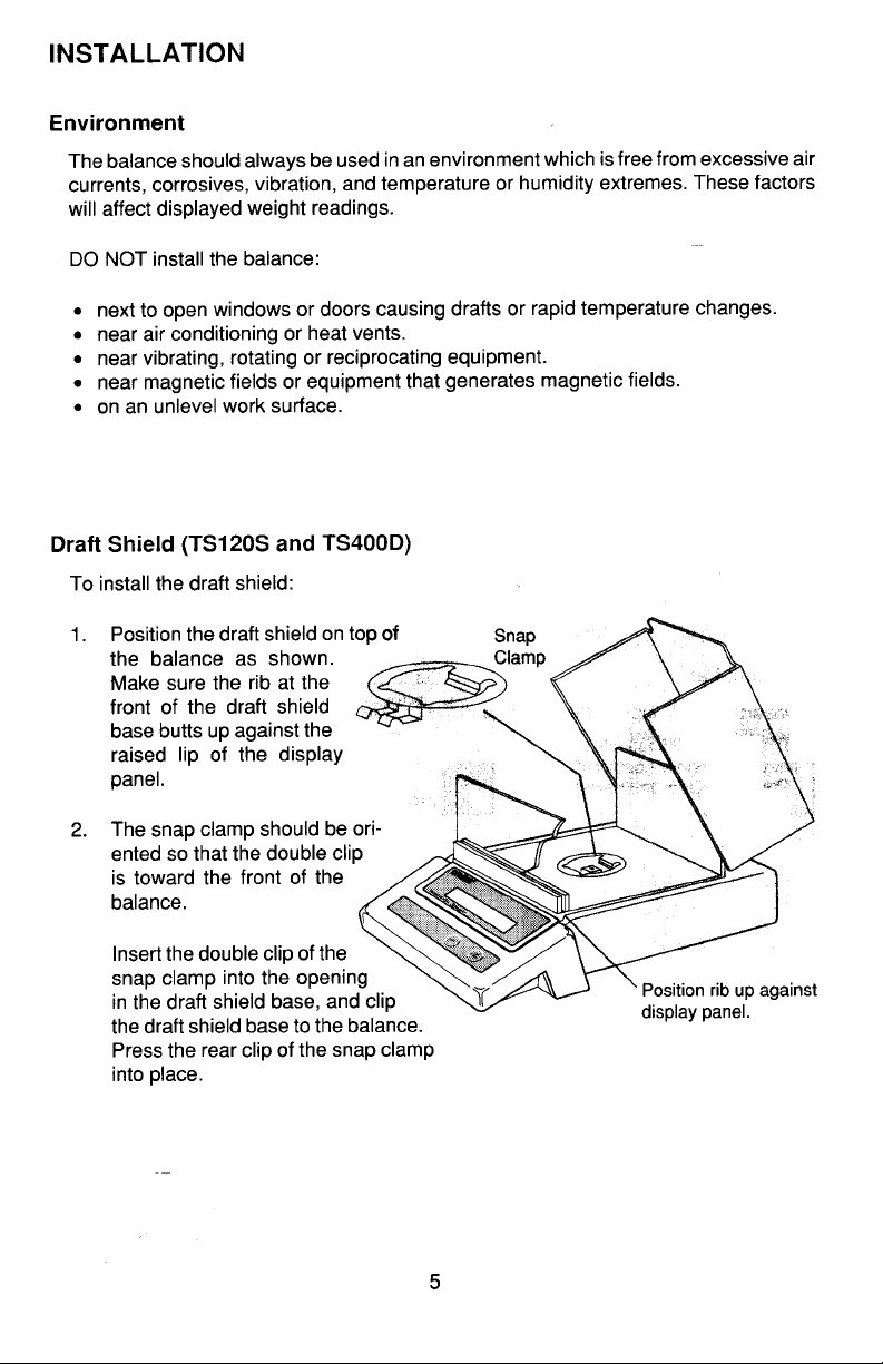
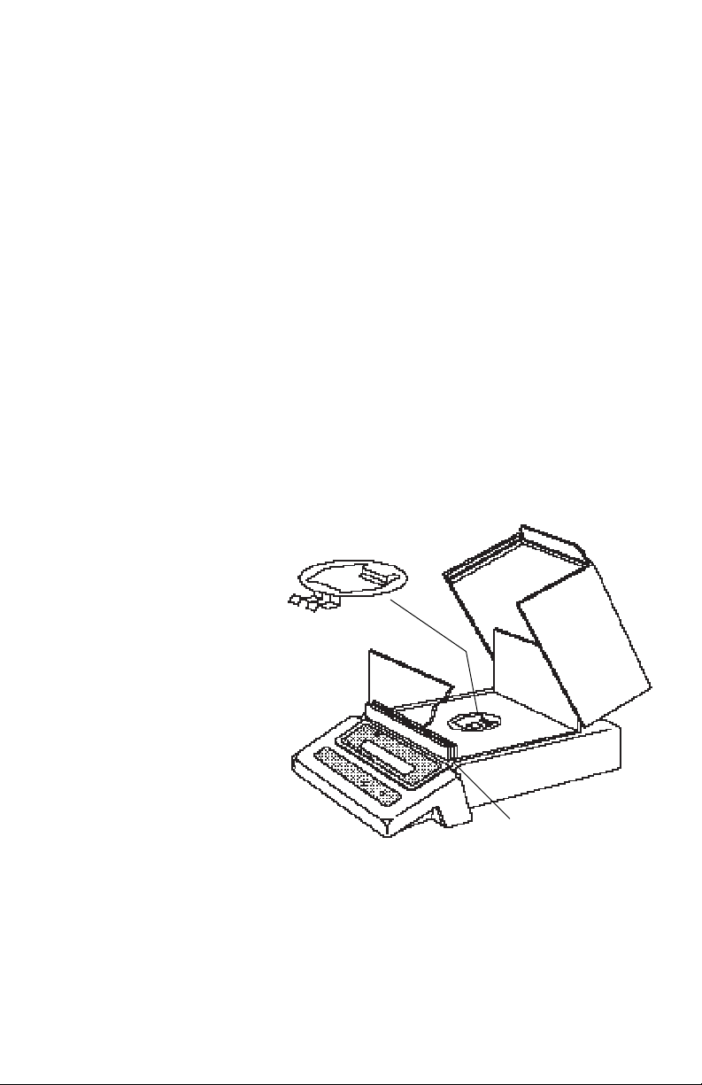
To install the draft shield:
1. Position the draft shield on top of
the balance as shown.
Make sure the rib at the
front of the draft shield
base butts up against the
raised lip of the display
panel.
2. The snap clamp should be oriented so that the double clip
is toward the front of the
balance.
Insert the double clip of the
snap clamp into the opening
in the draft shield base, and clip
the draft shield base to the balance.
Press the rear clip of the snap clamp
into place.
Position rib up against
display panel.
7
Page 26
Pan and Pan SupportPan and Pan Support
Pan and Pan Support
Pan and Pan SupportPan and Pan Support
Square PanSquare Pan
Square Pan
Square PanSquare Pan
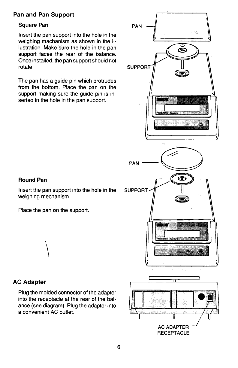
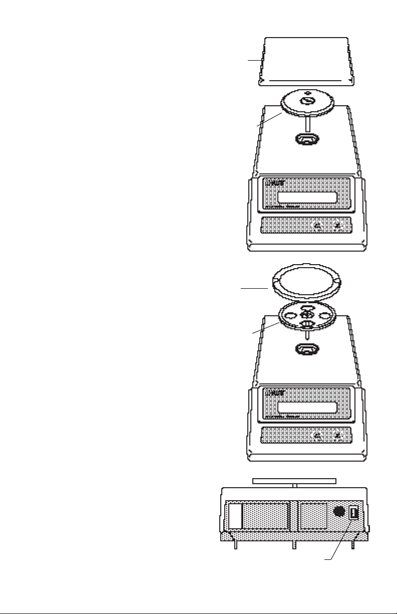
Insert the pan support into the hole in the
weighing mechanism as shown in the illustration. Make sure the hole in the pan
support faces the rear of the balance.
Once installed, the pan support should not
rotate.
The pan has a guide pin which protrudes
from the bottom. Place the pan on the
support making sure the guide pin is inserted in the hole in the pan support.
Round PanRound Pan
Round Pan
Round PanRound Pan
Insert the pan support into the hole in the
weighing mechanism.
PAN
SUPPORT
PAN
SUPPORT
Place the pan on the support.
AC AdapterAC Adapter
AC Adapter
AC AdapterAC Adapter
Plug the molded connector of the adapter
into the receptacle at the rear of the balance. Plug the adapter into a convenient
AC outlet. When power is applied to the
balance, it will begin a self test cycle.
During this time, the display will count
down from 10 and display the word CHEC.
AC ADAPTER
RECEPTACLE
8
Page 27
OPERATIONOPERATION
OPERATION
OPERATIONOPERATION
Turning the Balance ONTurning the Balance ON
Turning the Balance ON
Turning the Balance ONTurning the Balance ON
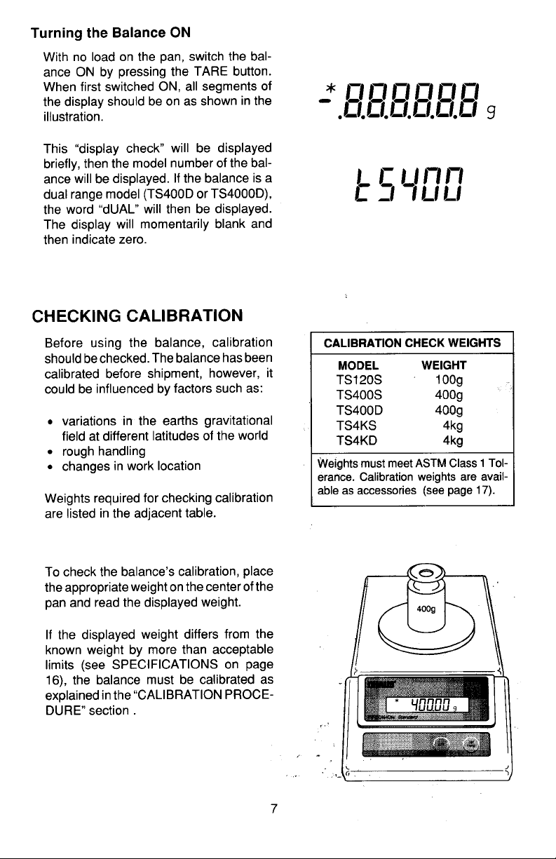
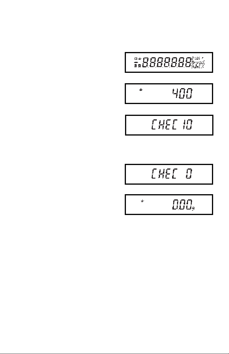
With no load on the pan, turn the balance
ON by pressing the ON TARE button.
When first switched ON, all segments of
the display should be on as shown in the
illustration.
This display check will be displayed briefly,
then the model number of the balance,
followed by a short countdown. The display will momentarily blank and then indicate zero. All of the displays shown at the
right only appear during initial power-up.
StabilizationStabilization
Stabilization
StabilizationStabilization
Before initally using the balance, allow
time for it to adjust to changes in environment. The balance need only be plugged
in to warm up. Recommended warm up
period is thirty minutes.
Auto Range ModelsAuto Range Models
Auto Range Models
Auto Range ModelsAuto Range Models
(TS400D and TS4KD)(TS400D and TS4KD)
(TS400D and TS4KD)
(TS400D and TS4KD)(TS400D and TS4KD)
•
•
•
Auto range balances offer both a fine
range (lower capacity/higher readability)
and a coarse range (higher capacity/lower
readability). When first turned on, the balance is in the fine range. It remains in this
range until the weight on the pan exceeds
the fine range capacity. When weight on
the pan is greater than the fine range
capacity, the balance switches to the
coarse range.
If weight on the pan falls back to within the
fine range capacity, coarse range readability remains in effect until you tare the
balance with no weight on the pan.
9
Page 28
Checking CalibrationChecking Calibration
Checking Calibration
Checking CalibrationChecking Calibration
Before using the balance, calibration
should be checked. The balance has been
calibrated before shipment, however, it
could be influenced by factors such as:
• Variations in the earths gravitational
field at different latitudes of the world.
• Rough handling.
• Changes in work location.
• Height above sea level.
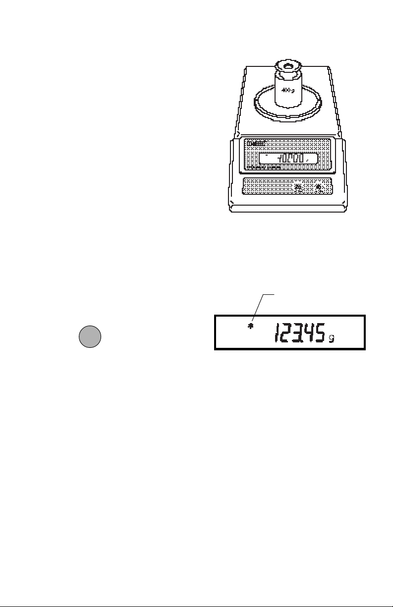
To check the balance’s calibration, place
a known mass on the center of the pan and
read the displayed weight.
If the displayed weight differs from the
known weight by more than acceptable
limits, refer to the Calibration Menu and
the Specifications at the rear of the manual.
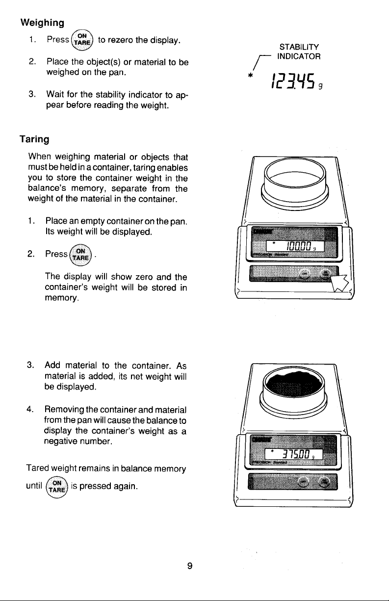
WeighingWeighing
Weighing
WeighingWeighing
STABILITY
INDICATOR
ONON
ON
1. Press to rezero the display.
ONON
TARETARE
TARE
TARETARE
2. Place the object(s) or material to be
weighed on the pan.
3. Wait for the stability indicator to appear before reading the weight.
10
Page 29
TaringTaring
Taring
TaringTaring
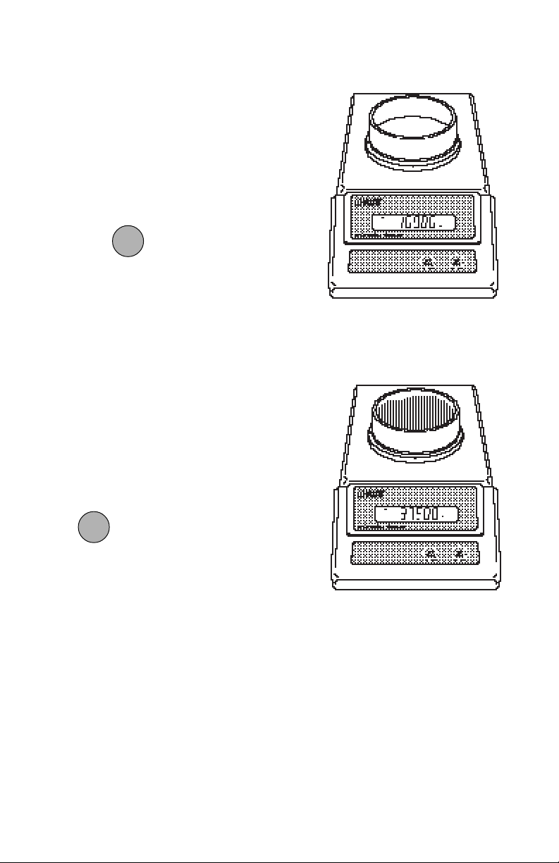
When weighing material or objects that
must be held in a container, taring enables
you to store the container weight in the
balance’s memory, separate from the
weight of the material in the container.
1. Place an empty container on the pan.
Its weight will be displayed.
ONON
ON
2. Press
ONON
TARETARE
TARE
TARETARE
.
The display will show zero and the
container’s weight will be stored in
memory.
3. Add material to the container. As
material is added, its net weight will
be displayed.
4. Removing the container and material
from the pan will cause the balance
to display the container’s weight as a
negative number.
Tared weight remains in balance memory
ONON
ON
ONON
TARETARE
is pressed again.
TARE
until
TARETARE
11
Page 30
USING MENUS TO CONFIGURE THE BALANCEUSING MENUS TO CONFIGURE THE BALANCE
USING MENUS TO CONFIGURE THE BALANCE
USING MENUS TO CONFIGURE THE BALANCEUSING MENUS TO CONFIGURE THE BALANCE
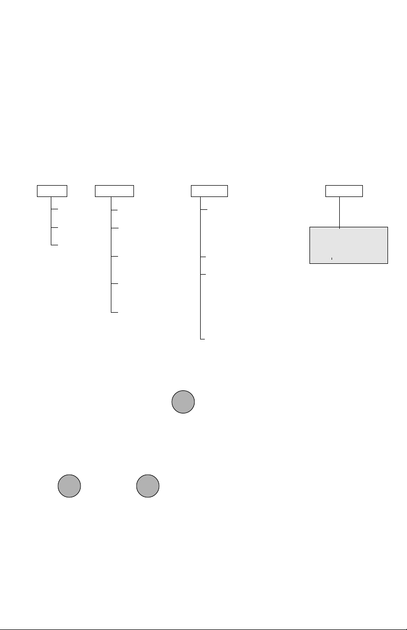
Precision Standard balances contain four display menus which enable you to calibrate
and configure the balance for your specific operating requirements.
Calibration Menu:Calibration Menu:
Calibration Menu: Used to calibrate the balance for span or linearity.
Calibration Menu:Calibration Menu:
User MenuUser Menu
User Menu: Used to adapt balance to environmental condtions.
User MenuUser Menu
Setup Menu:Setup Menu:
Setup Menu: Used to enable, disable or customize different balance features.
Setup Menu:Setup Menu:
Print Menu:Print Menu:
Print Menu: Used to configure the RS232 interface.
Print Menu:Print Menu:
CAL
SPAN
LIN
END
USER
RESET
AL
0,
STB
.5d,
AUTO- 0
OFF,
END
11
1, 2, 3
11
1d1d
1d, 2d, 5d
1d1d
.5d.5d
.5d, 1d,3d
.5d.5d
SETUP
SEL
g, dwt, ct, oz, ozt, GN,
taels 1,2,3, mommes,
lb, lb:oz
Sr
LOCSW
Calibration
User
Setup
Print
PRINT
NOTE:
PRINT menu appears only
when RS232 option is installed.
End
END
ONON
ON
To access a menu, press and hold until desired menu appears, then release it.
ONON
TARETARE
TARE
TARETARE
Original factory default settings are shown in boldface type.
Use these buttons to step through menus and select submenus:
OFFOFF
OFF
OFFOFF
MODEMODE
MODE
MODEMODE
next select
selection displayed item
ONON
ON
ONON
TARETARE
TARE
TARETARE
12
Page 31
CALIBRATION MENUCALIBRATION MENU
CALIBRATION MENU
CALIBRATION MENUCALIBRATION MENU
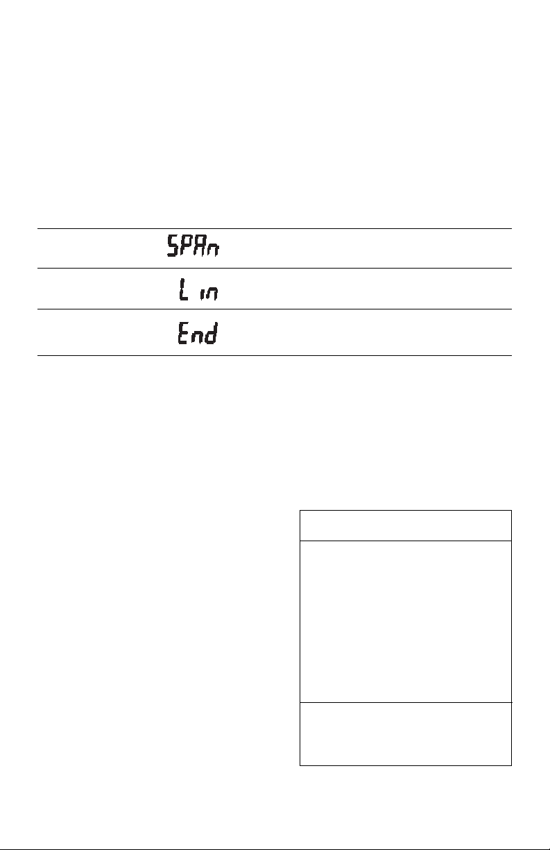
Precision Standard balances can be calibrated in two ways: Span calibration or
Linearity calibration. Span calibration resets the balance’s weighing range using two
weight values: zero and a weight value at or near the balance’s capacity. Linearity
calibration minimizes deviation between actual and displayed weights within the
balance’s weighing range. Three weight values are used: zero, a weight value within
the balances weighing range, and a weight value at or near the balance’s specified
capacity. The following table shows the sequence in which submenus appear on the
Calibration menu.
CALIBRATION MENU TABLECALIBRATION MENU TABLE
CALIBRATION MENU TABLE
CALIBRATION MENU TABLECALIBRATION MENU TABLE
Selects span calibration.
Selects linearity calibration.
Used to exit the Calibration menu.
Calibration Menu ProtectionCalibration Menu Protection
Calibration Menu Protection
Calibration Menu ProtectionCalibration Menu Protection
The calibration menu may be locked out to
prevent unauthorized personnel from
changing calibration. To lock out the calibration menu, refer to section titled Menu
Lock-Out Protection.
NOTENOTE
NOTE: If calibration has been locked out,
NOTENOTE
you will not be able to access it.
Calibration WeightsCalibration Weights
Calibration Weights
Calibration WeightsCalibration Weights
Before beginning calibration, make sure
weights are on hand. If you begin calibration and realize weights are not available,
either turn the balance off, or go through
the procedure without weights. The balance will use previously stored calibration
data. Calibration should be performed as
necessary to ensure accurate weighing.
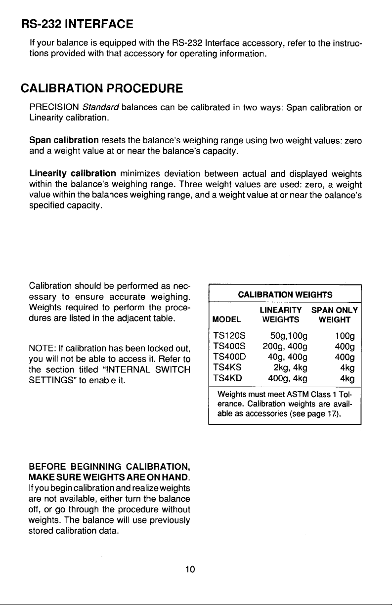
Weights required to perform the procedures are listed in the adjacent table.
CALIBRATION WEIGHTSCALIBRATION WEIGHTS
CALIBRATION WEIGHTS
CALIBRATION WEIGHTSCALIBRATION WEIGHTS
LINEARITYLINEARITY
LINEARITY
MODELMODEL
MODEL
MODELMODEL
LINEARITYLINEARITY
WEIGHTSWEIGHTS
WEIGHTS
WEIGHTSWEIGHTS
TS120 50g, 100g 100g
TS200 100g, 200g 200g
TS400 200g, 400g 400g
TS400D 50g, 400g 400g
TS600 200g, 500g 500g
TS4K 2kg, 4kg 4kg
TS2K 1kg, 2kg 2kg
TS4KD 500g, 4kg 4kg
It is recommended that masses must
meet or exceed ASTM Class 1 Tolerance. Calibration masses are available
as accessories.
13
SPAN ONLYSPAN ONLY
SPAN ONLY
SPAN ONLYSPAN ONLY
WEIGHTWEIGHT
WEIGHT
WEIGHTWEIGHT
Page 32
Span CalibrationSpan Calibration
Span Calibration
Span CalibrationSpan Calibration
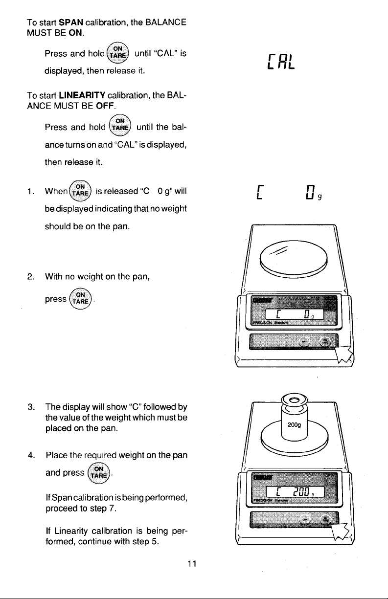
ONON
ON
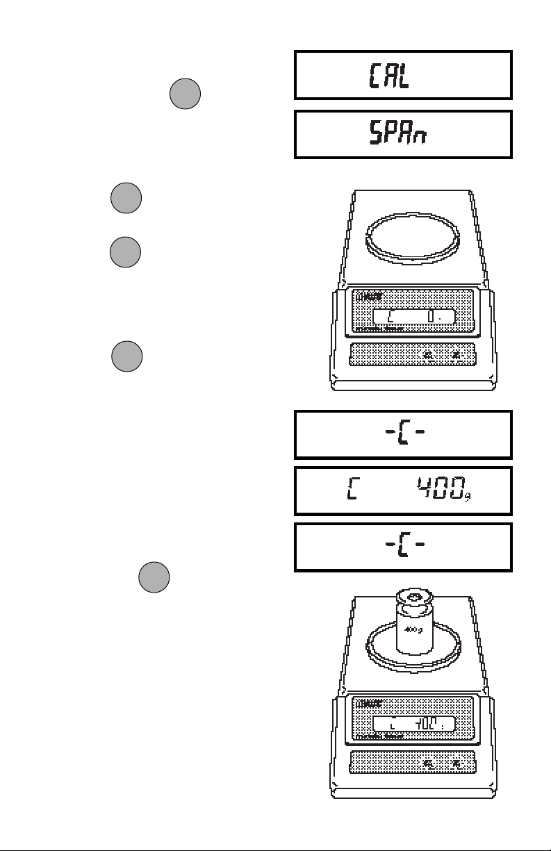
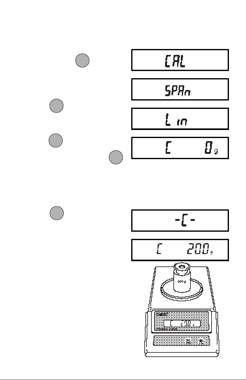
1. Press and hold until CAL is
ONON
TARETARE
TARE
TARETARE
displayed, then release it. Balance
will display SPAN.
ONON
ON
2. Press
3. When
ONON
.
TARETARE
TARE
TARETARE
ONON
ON
ONON
is released, C 0g will be
TARETARE
TARE
TARETARE
displayed indicating that no weight
should be on the pan.
ONON
ON
4. Press
ONON
. The display will show
TARETARE
TARE
TARETARE
-C- followed by the value of the weight
which must be placed on the pan.
NOTE: NOTE:
NOTE: Do not disturb the balance when
NOTE: NOTE:
-C- is displayed. Disturbances will
result in improper calibration.
5. Place the required weight on the pan
ONON
ON
and press
ONON
. The display will
TARETARE
TARE
TARETARE
show -C- while the balance recalibrates.
6. When the weight on the pan is displayed along with the current unit
indicator, the balance is recalibrated.
14
Page 33
Linearity CalibrationLinearity Calibration
Linearity Calibration
Linearity CalibrationLinearity Calibration
1. Turn Balance on. After zero reading,
ONON
ON
ONON
TARETARE
TARE
TARETARE
press and hold
until CAL is
displayed, then release. Balance will
display SPAN.
OFFOFF
OFF
OFFOFF
2. Press
and the display will show
MODEMODE
MODE
MODEMODE
LIN.
ONON
ON
ONON
TARETARE
TARE
TARETARE
3. Press
to start the Linearity Cali-
bration Procedure. When the
is released, C 0g will be displayed,
indicating that no weight should be in
the pan.
ONON
ON
ONON
TARETARE
TARE
TARETARE
ONON
ON
4. Press
ONON
. The display will show
TARETARE
TARE
TARETARE
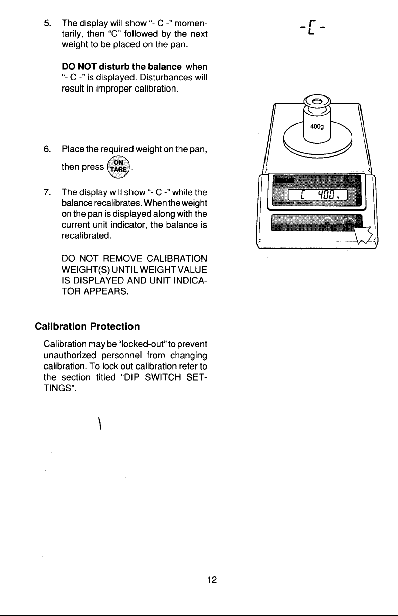
-C- followed by the value of the weight
which must be placed on the pan.
5. Place the required weight on the pan.
15
Page 34
ONON
ON
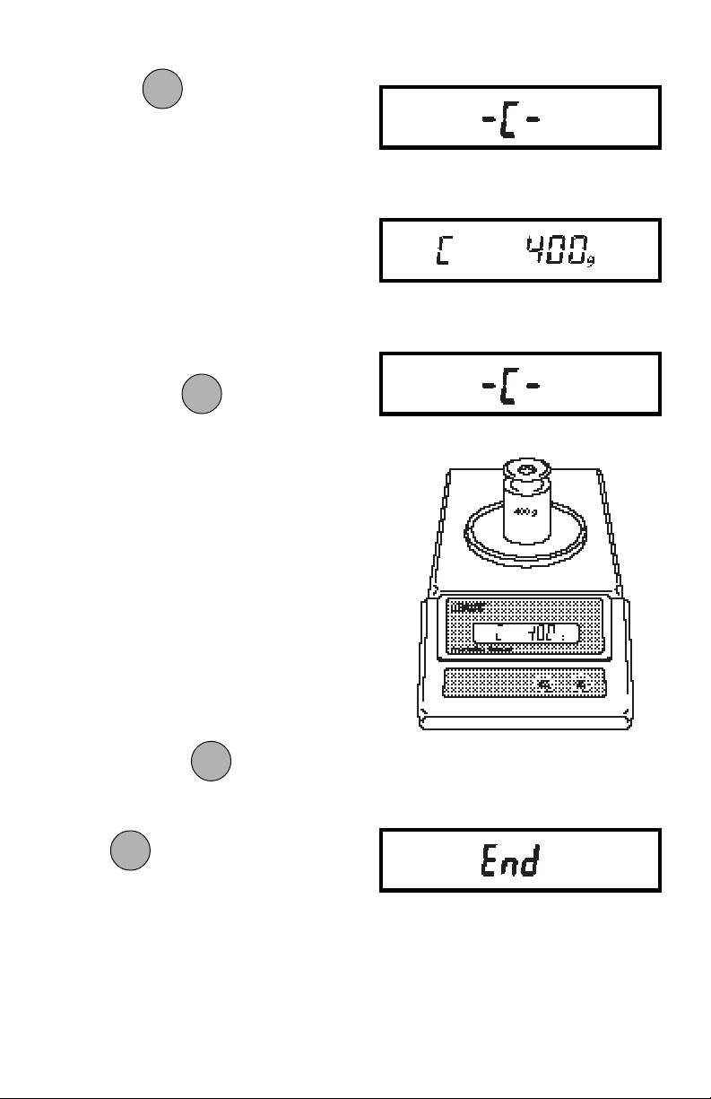
6. Press
ONON
. The display will show
TARETARE
TARE
TARETARE
-C- momentarily, then C followed by
the next weight to be placed on the
pan. Do not disturb the balance when
-C- is displayed. Disturbances will
result in improper calibration.
7. Place the required weight on the pan,
ONON
ON
then press
ONON
. The display will
TARETARE
TARE
TARETARE
show -C- while the balance recalibrates. When the weight on the pan is
displayed along with the current indicator, the balance is recalibrated.
EndEnd
End
EndEnd
If you have entered the Calibration menu
and do not wish to calibrate the balance,
use END to return to normal weighing
operations.
OFFOFF
OFF
OFFOFF
MODEMODE
MODE
Repeately press
MODEMODE
until End is dis-
played.
ONON
ON
ONON
Press
, when released, the balance
TARETARE
TARE
TARETARE
will returned to normal weighing operations.
16
Page 35
USER MENUUSER MENU
USER MENU
USER MENUUSER MENU
The User menu is used to adapt the balance to environmental conditions. It contains
submenus which enable you to reset the balance to factory default settings or to select
specific range settings. Access to the User menu can be disabled using the Lock Out
switch. The following table shows the sequence in which submenus appear on the
User menu.
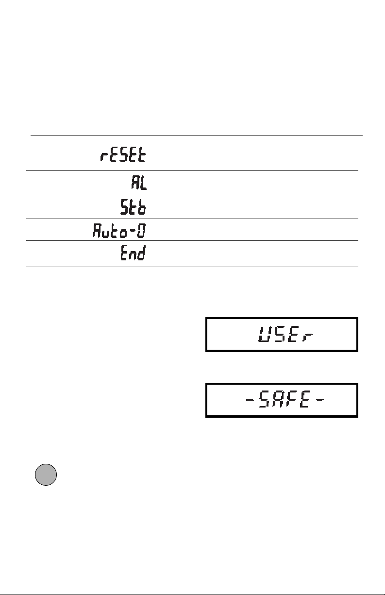
USER MENU TABLEUSER MENU TABLE
USER MENU TABLE
USER MENU TABLEUSER MENU TABLE
Sets all submenus below to original
factory default settings. Reset does not
appear if menu has been locked out.
Specifies the averaging level.
Specifies the desired stability range.
Sets Auto-Zero threshold.
Used to exit the Setup menu and store
your selections.
User Menu ProtectionUser Menu Protection
User Menu Protection
User Menu ProtectionUser Menu Protection
The User menu may be locked out to
prevent unauthorized personnel from
changing the settings. To lock out the
User menu, refer to the section titled Menu
Lock-Out Protection.
NOTENOTE
NOTE: If -SAFE- is displayed, the User
NOTENOTE
menu has been locked out. Settings may
be viewed but not changed. See the Menu
Lock-Out Protection section to enable it
for making changes.
To access the User menu, press and hold
ONON
ON
ONON
until USER is displayed, then re-
TARETARE
TARE
TARETARE
lease it.
17
Page 36
To access a submenu:
OFFOFF
OFF
1. Repeatedly press
OFFOFF
until the de-
MODEMODE
MODE
MODEMODE
sired submenu is displayed.
ONON
ON
2. Press
ONON
to select the displayed
TARETARE
TARE
TARETARE
submenu.
NOTENOTE
NOTE: You must use END to store any
NOTENOTE
changes you make to the User menu.
The following sections describe each item
on the User menu in detail.
Reset to Factory DefaultsReset to Factory Defaults
Reset to Factory Defaults
Reset to Factory DefaultsReset to Factory Defaults
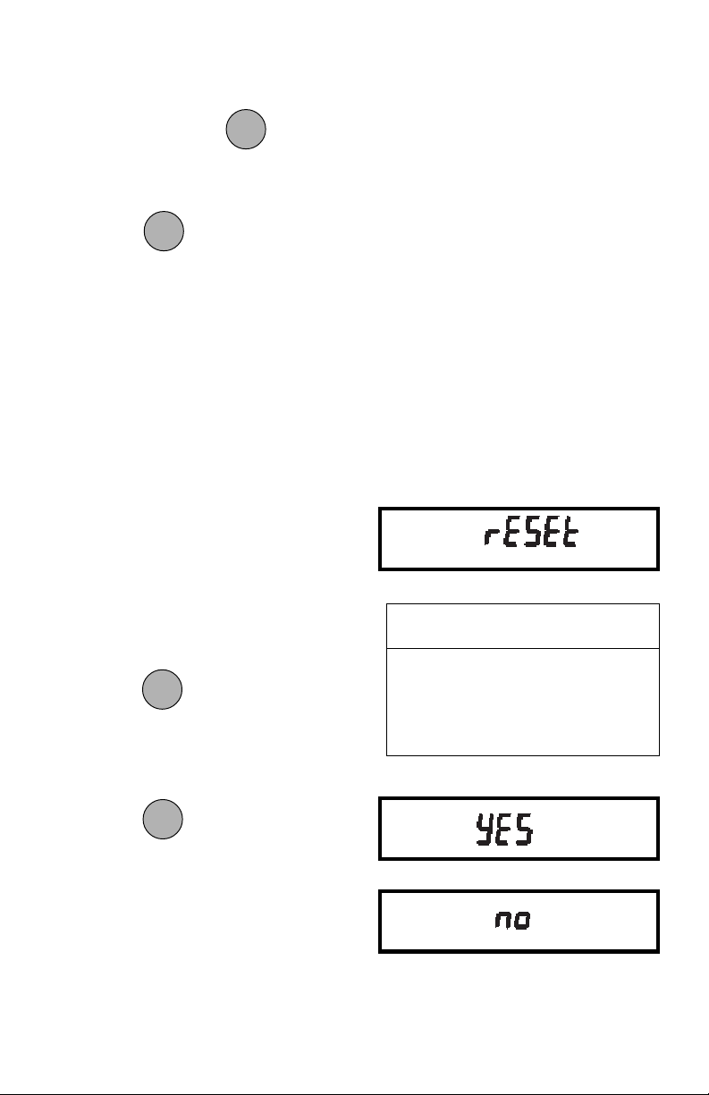
This submenu enables you to reset all
User menu selections to the factory default settings outlined in the adjacent table.
To reset to factory defaults:
1. Access the RESET submenu.
OFFOFF
OFF
OFFOFF
MODEMODE
MODE
2. Press
MODEMODE
to change the setting.
Select YES to reset settings or,
no to leave current settings.
ONON
ON
Press
ONON
to accept the displayed
TARETARE
TARE
TARETARE
setting.
USER MENUUSER MENU
USER MENU
USER MENUUSER MENU
FACTORY DEFAULTSFACTORY DEFAULTS
FACTORY DEFAULTS
FACTORY DEFAULTSFACTORY DEFAULTS
Averaging Level AL 1
Stability Range 1d
Auto-Zero Tracking .5d
18
Page 37
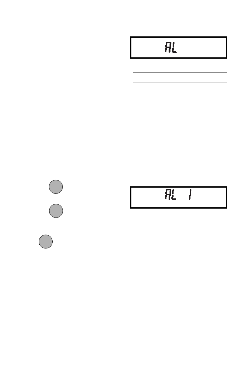
Averaging LevelAveraging Level
Averaging Level
Averaging LevelAveraging Level
Averaging level compensates for vibration or excessive air currents. During operation, the balance continually takes
weight readings from the weighing cell.
Successive readings are then digitally processed to achieve a stabilized display.
Use this submenu to specify how much
processing you need to obtain stable results.
NOTE: Averaging level does not affect
balance accuracy.
AVERAGING LEVELAVERAGING LEVEL
AVERAGING LEVEL
AVERAGING LEVELAVERAGING LEVEL
AL 0 reduced stability, fastest
stabilization time
ALAL
1 normal stability, normal1 normal stability, normal
AL
1 normal stability, normal
ALAL
1 normal stability, normal1 normal stability, normal
stabilization timestabilization time
stabilization time
stabilization timestabilization time
Select one of four averaging levels using
the adjacent table as a guide.
To view or change the averaging level:
1. Access the AL submenu to display
the current setting.
OFFOFF
OFF
OFFOFF
MODEMODE
MODE
Press
MODEMODE
to change the setting.
ONON
ON
ONON
to accept the displayed
TARETARE
TARE
TARETARE
2. Press
setting.
ONON
ON
When
ONON
is released, AL will be dis-
TARETARE
TARE
TARETARE
played again and the Setup menu will be
returned.
AL 2 more stability, slow stabi-
lization time
AL 3 maximum stability, slow-
est stabilization time
19
Page 38
Stability RangeStability Range
Stability Range
Stability RangeStability Range
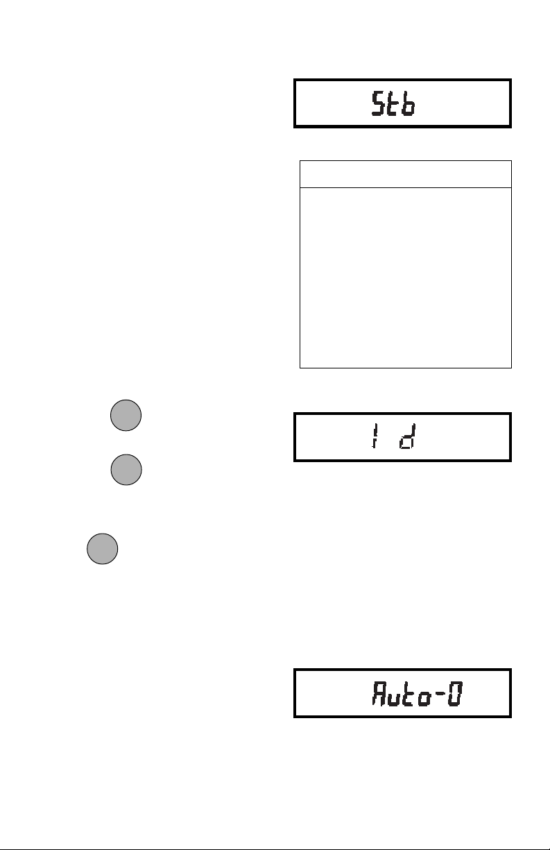
The stability range specifies how much a
displayed weight may change while the
stability indicator remains ON. When displayed weight changes beyond the allowable range, the stability indicator turns
OFF indicating an unstable condition. Precision Standard balances permit you to
select one of four stability ranges (in divisions) as shown in the table.
When the RS232 interface is configured to
print stable data only, the stability range
also governs data output. Displayed data
will only be output if it is within the selected
stability range.
To view or change the stability range:
1. Access the Stb submenu to display
the current setting.
OFFOFF
OFF
2. Press
OFFOFF
to change the setting.
MODEMODE
MODE
MODEMODE
STABILITY RANGESTABILITY RANGE
STABILITY RANGE
STABILITY RANGESTABILITY RANGE
..
.5d smallest range: stability indi-
..
cator is ON only when displayed weight is within .5 divisions
1d1d
reduced rangereduced range
1d
reduced range
1d1d
reduced rangereduced range
2d normal range
5d largest range: stability indi-
cator is ON even though displayed weight changes
slightly
ONON
ON
Press to accept the displayed
ONON
TARETARE
TARE
TARETARE
setting.
ONON
ON
When is released, Stb will be dis-
ONON
TARETARE
TARE
TARETARE
played again and the Setup menu will be
returned.
Auto-ZeroAuto-Zero
Auto-Zero
Auto-ZeroAuto-Zero
Auto-Zero minimizes the effects of temperature changes and shift on the zero
reading. By defining a threshold level in
divisions, the balance maintains the zero
display until the threshold is exceeded.
This submenu permits you to select one of
three threshold levels, or turn the feature
OFF. Auto-Zero only functions when the
display reads zero.
20
Page 39
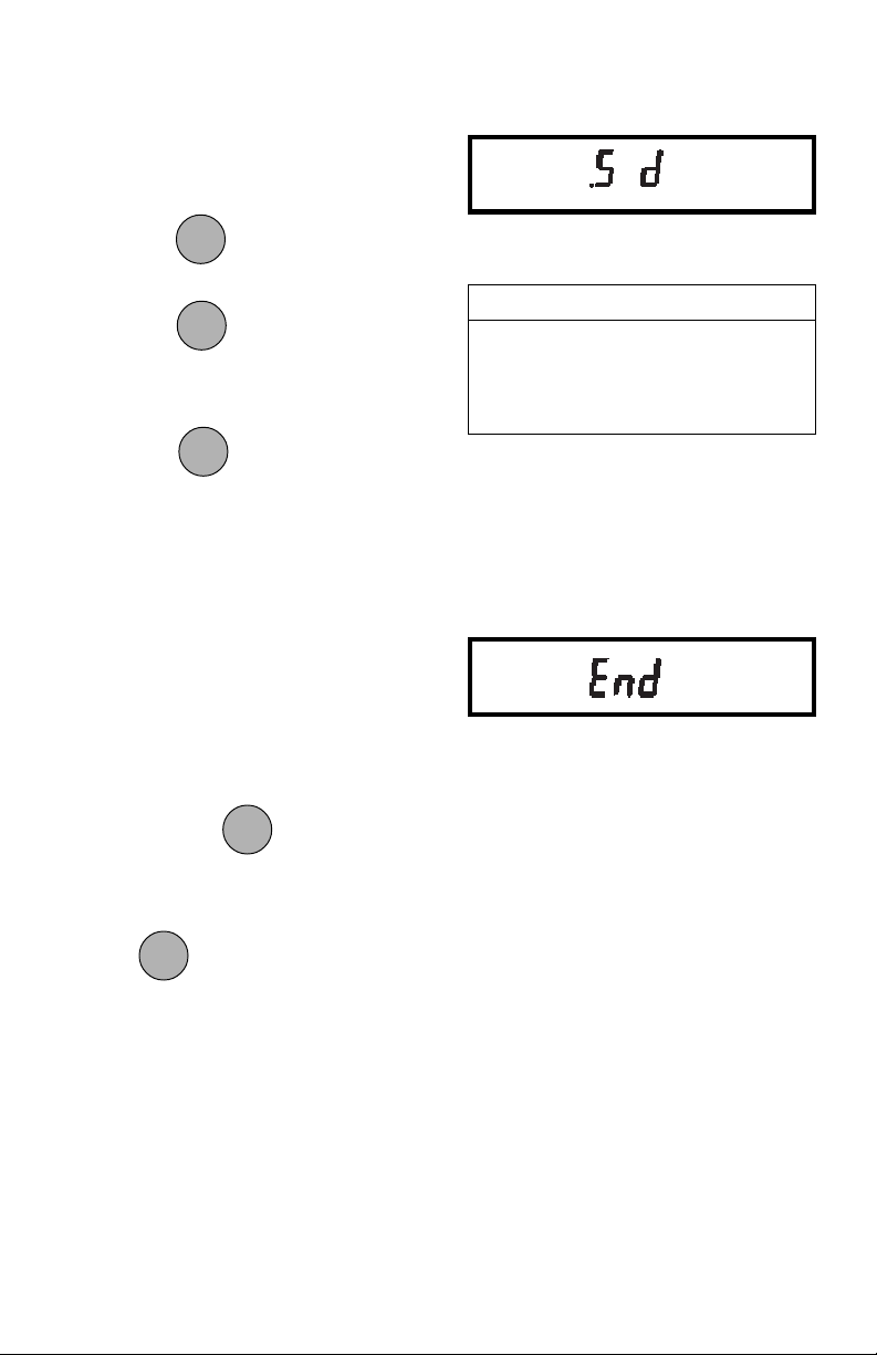
To view or change the Auto-Zero setting:
1. Access the Auto-0 submenu to display the current setting.
OFFOFF
OFF
Press
OFFOFF
to change the setting.
MODEMODE
MODE
MODEMODE
ONON
ON
ONON
TARETARE
TARE
TARETARE
to accept the displayed
2. Press
setting.
When
is released, Auto-0 will
ONON
ON
ONON
TARETARE
TARE
TARETARE
be displayed again and the User menu
will be returned.
EndEnd
End
EndEnd
You must use END to exit the User menu.
Changes you make in the User menuChanges you make in the User menu
Changes you make in the User menu
Changes you make in the User menuChanges you make in the User menu
are only stored in memory if you useare only stored in memory if you use
are only stored in memory if you use
are only stored in memory if you useare only stored in memory if you use
END.END.
END.
END.END.
AUTO ZEROAUTO ZERO
AUTO ZERO
AUTO ZEROAUTO ZERO
OFF turns Auto-Zero OFF
.5d.5d
sets threshold to .5 divisionssets threshold to .5 divisions
.5d
sets threshold to .5 divisions
.5d.5d
sets threshold to .5 divisionssets threshold to .5 divisions
1d sets threshold to 1 division
3d sets threshold to 3 divisions
To exit the User menu and store your
ONON
ON
ONON
settings, press
when End is dis-
TARETARE
TARE
TARETARE
played.
ONON
ON
When
ONON
is released, the balance will
TARETARE
TARE
TARETARE
be returned to normal weighing operations.
21
Page 40
SETUP MENUSETUP MENU
SETUP MENU
SETUP MENUSETUP MENU
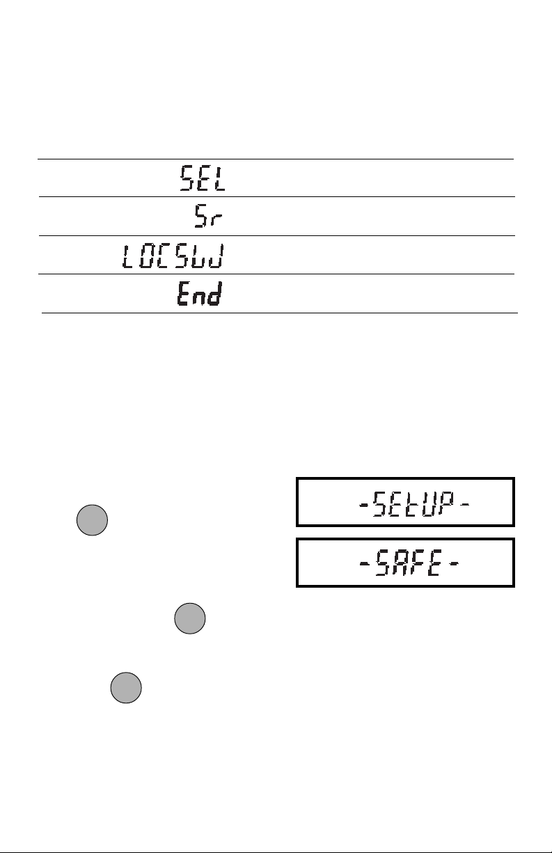
The Setup menu enables you to retain program balance parameters once they have
been set. Access to the Setup menu can be disabled using the Lock Out switch. The
following table shows the sequence in which submenus appear on the Setup menu.
SETUP MENU TABLE SETUP MENU TABLE
SETUP MENU TABLE
SETUP MENU TABLE SETUP MENU TABLE
Enables the selection of weighing
units.
Indicates the software version of the
balance.
Enables individual or all menus to be
locked out.
Used to exit the Setup menu and
store your selections.
Setup Menu ProtectionSetup Menu Protection
Setup Menu Protection
Setup Menu ProtectionSetup Menu Protection
The Setup menu may be locked-out to prevent unauthorized personnel from changing
settings. To lock out the Setup menu, refer to the section titled Menu Lock-Out
Protection.
NOTENOTE
NOTE: If -SAFE- is displayed, the Setup menu has been locked out. Settings may be
NOTENOTE
viewed but not changed. See the Menu Lock-Out Protection section to enable it for
making changes.
To access the Setup menu, press and
ONON
ON
ONON
hold
until SETUP is displayed, then
TARETARE
TARE
TARETARE
release it.
To access a submenu:
OFFOFF
OFF
1. Repeatedly press
OFFOFF
until the de-
MODEMODE
MODE
MODEMODE
sired submenu is displayed.
ONON
ON
2. Press
ONON
to select the displayed
TARETARE
TARE
TARETARE
submenu.
NOTENOTE
NOTE: You must use END to store any
NOTENOTE
changes you make to the Setup menu.
The following sections describe each
item on the Setup menu in detail.
22
Page 41
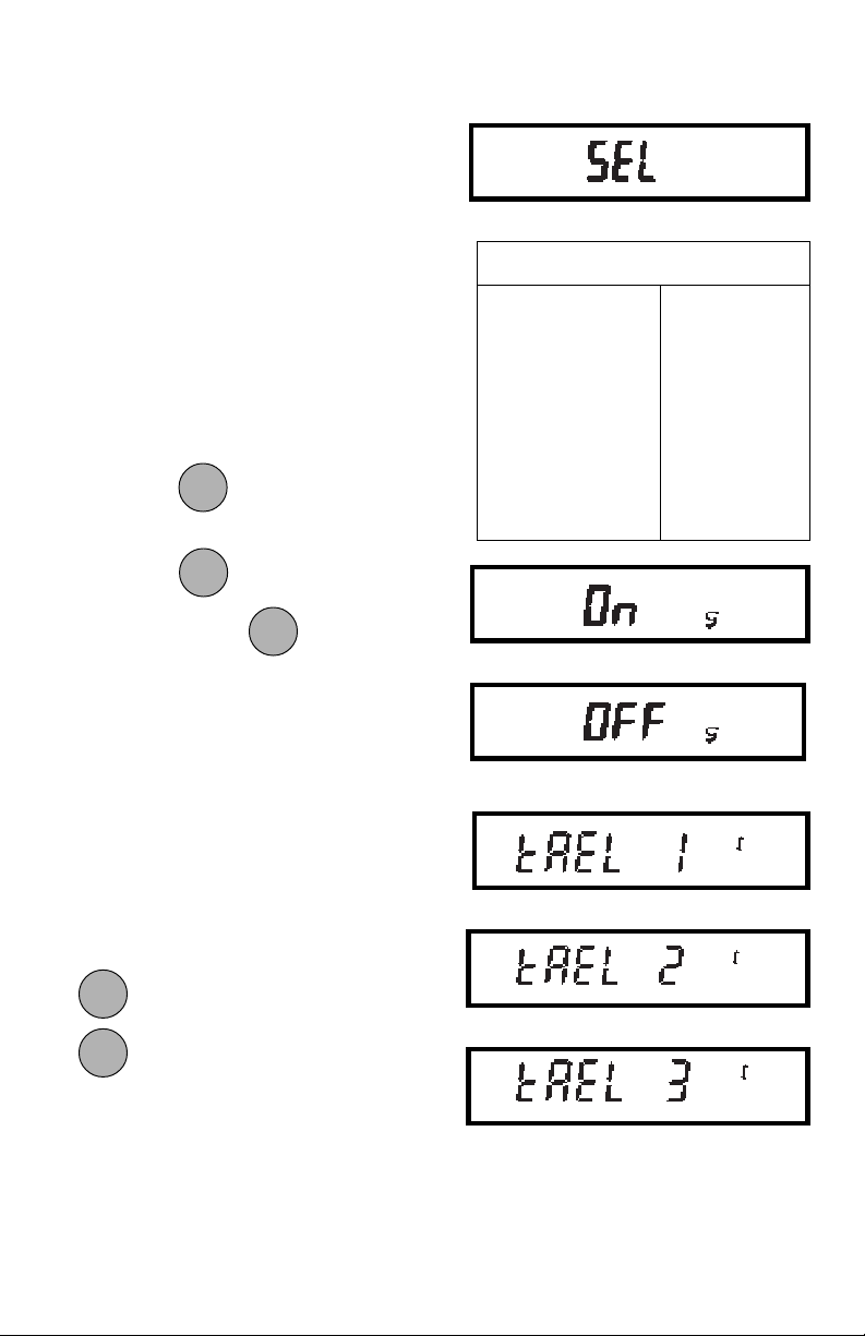
Unit SelectionUnit Selection
Unit Selection
Unit SelectionUnit Selection
Unit selection permits you to specify which
weighing units will be enabled for use
during operation. The adjacent table lists
the units available.
To enable or disable the various weighing
units, use the following procedure:
1. Access the SEL menu.
2. The display will show the grams unit
indicator (g) along with the current
status (ON/OFF).
OFFOFF
OFF
3. Press
4. Press
status. When is released, the
OFFOFF
to change the status.
MODEMODE
MODE
MODEMODE
ONON
ON
ONON
to accept the displayed
TARETARE
TARE
TARETARE
ONON
ON
ONON
TARETARE
TARE
TARETARE
display will show the next unit indicator with the current status.
5. Set each unit ON or OFF as in step 3.
TaelsTaels
Taels
TaelsTaels
If taels are enabled, you will be required to
choose one of three different taels: Hong
Kong, Singapore, or Taiwan.
Weighing Units
g grams : mommes
dwt pennyweight ct carats
oz t troy ounces t taels
lb lb:oz
gn oz
(Hong Kong)
When the display shows TAEL 1, press
OFFOFF
OFF
OFFOFF
to change to another tael, press
MODEMODE
MODE
MODEMODE
ONON
ON
ONON
to accept the displayed tael.
TARE TARE
TARE
TARE TARE
When the last weighing unit has been set,
the display will show SEL again and the
Setup menu will be returned.
(Singapore)
(Taiwan)
23
Page 42
LockswitchLockswitch
Lockswitch
LockswitchLockswitch
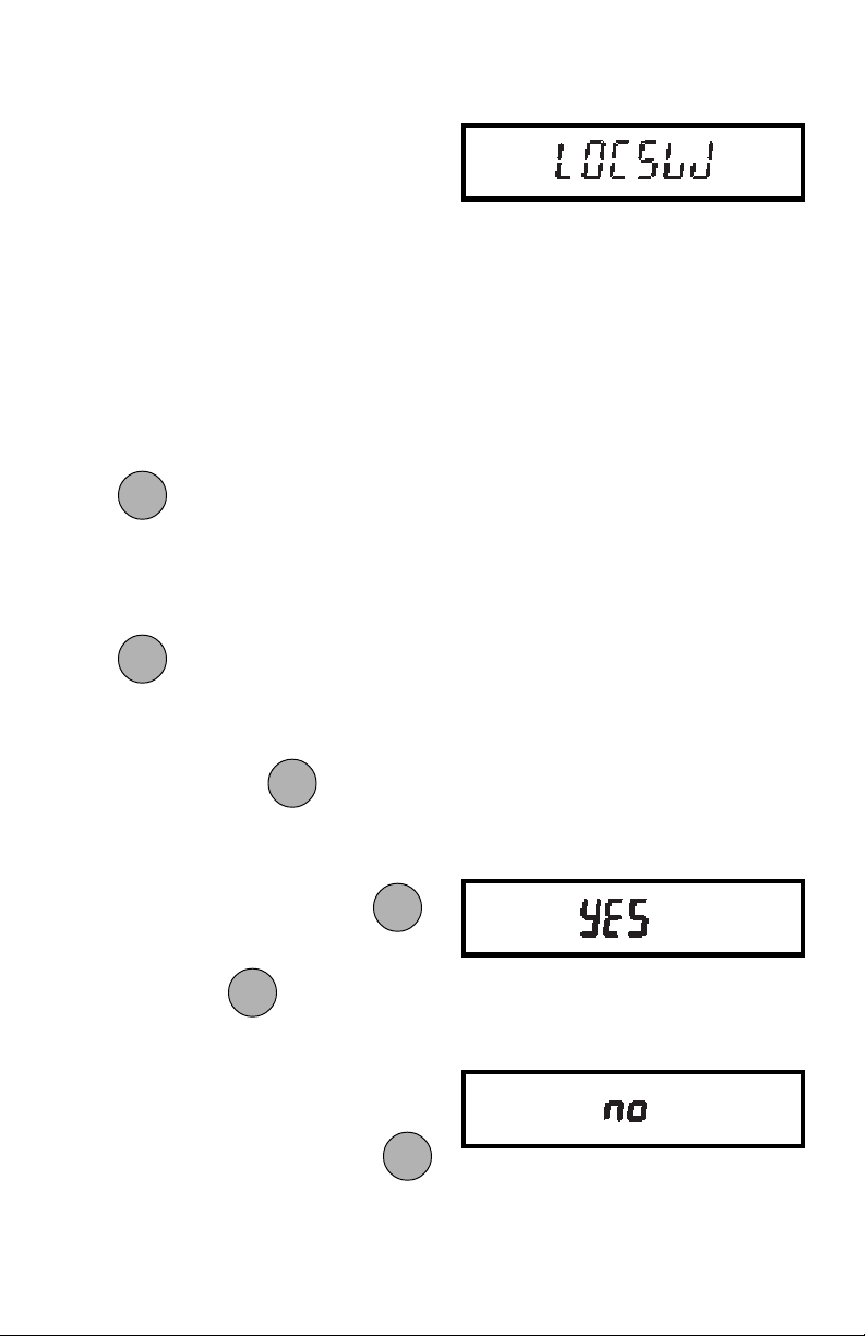
Lockswitch enables you to lock out one or
more menu selections. Each menu can be
individually locked on or off after all functions have been set. The Calibration,
User, and Setup menus can be individually locked on or off by selecting the
appropriate menu and then locked by the
switch located under the right hand side of
the control panel. Before performing the
lock out procedure, decide which functions of the balance are to be locked on or
off.
1. Access the LOCSW submenu. When
ONON
ON
ONON
is released, the LOCSW sub-
TARETARE
TARE
TARETARE
menu is displayed.
2. To access one or more menus, press
ONON
ON
ONON
to select the calibration menu,
TARETARE
TARE
TARETARE
-CAL- is displayed.
OFFOFF
OFF
OFFOFF
MODEMODE
MODE
NOTENOTE
NOTE: Pressing changes the
NOTENOTE
MODEMODE
selection to the other menus.
3. To select a YES or NO, press
OFFOFF
OFF
NOTENOTE
NOTE: The switch acts as a
NOTENOTE
OFFOFF
MODEMODE
MODE
MODEMODE
toggle and can select either YES or
NO.
4. To confirm your selection, press
again. The display indicates the last
menu you were in.
OFFOFF
OFF
OFFOFF
MODEMODE
MODE
MODEMODE
ONON
ON
ONON
TARETARE
TARE
TARETARE
.
24
Page 43
5. To lock out the other menus, press
OFFOFF
OFF
OFFOFF
and repeat the procedure in
MODEMODE
MODE
MODEMODE
steps 3 and 4.
EndEnd
End
EndEnd
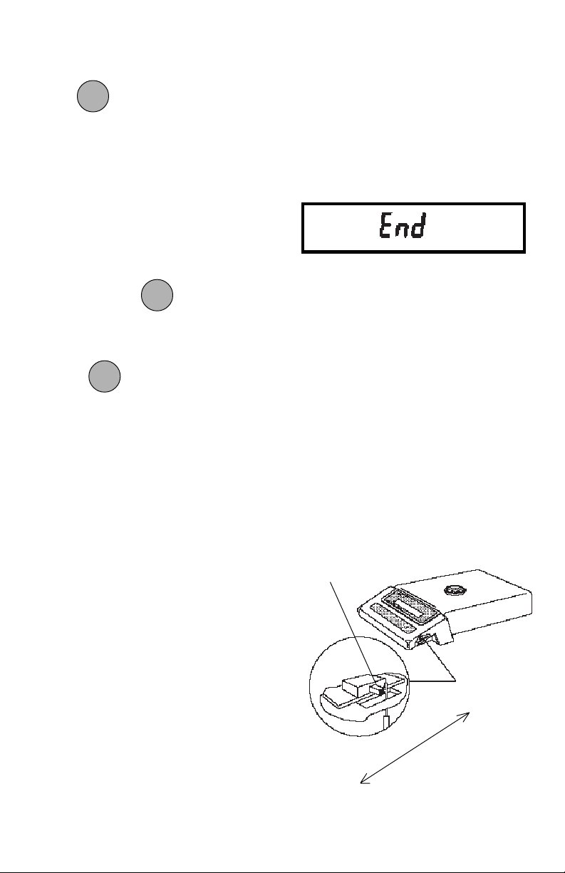
You must use END to exit the Setup menu.
Changes you make in the Setup menuChanges you make in the Setup menu
Changes you make in the Setup menu
Changes you make in the Setup menuChanges you make in the Setup menu
are only stored in memory if you useare only stored in memory if you use
are only stored in memory if you use
are only stored in memory if you useare only stored in memory if you use
END.END.
END.
END.END.
To exit the Setup menu and store your
ONON
ON
ONON
settings, press
when END is dis-
TARE TARE
TARE
TARE TARE
played.
ONON
ON
When
ONON
is released, the balance will
TARETARE
TARE
TARETARE
be returned to normal weighing operations.
MENU LOCK-OUT PROTECTIONMENU LOCK-OUT PROTECTION
MENU LOCK-OUT PROTECTION
MENU LOCK-OUT PROTECTIONMENU LOCK-OUT PROTECTION
Access to the Calibration, User, and Setup
menus, can be disabled using the lock out
switch located under the right side of the
balance, near the display.
1. Turn the display off and unplug the
power cord.
2. Slide the balance toward you, with
the front over the edge of a table.
(You can also turn the balance on its
left side, but if you do, you MUST
remove the pan and spill ring first!)
3. Locate hole under display where
switch is located.
4. Using a small screwdriver, slide the
switch forward for LOCKED or back
for UNLOCKED.
5. Plug in the power cord and turn on the
balance.
25
LOCK OUT
SWITCH
UNLOCK
LOCK
Page 44
CARE AND MAINTENANCECARE AND MAINTENANCE
CARE AND MAINTENANCE
CARE AND MAINTENANCECARE AND MAINTENANCE
To keep the balance operating properly, the housing and pan should be kept clean and
free from foreign material. If necessary, a cloth dampened with a mild detergent may
be used. Keep calibration weights in a safe dry place.
TROUBLESHOOTINGTROUBLESHOOTING
TROUBLESHOOTING
TROUBLESHOOTINGTROUBLESHOOTING
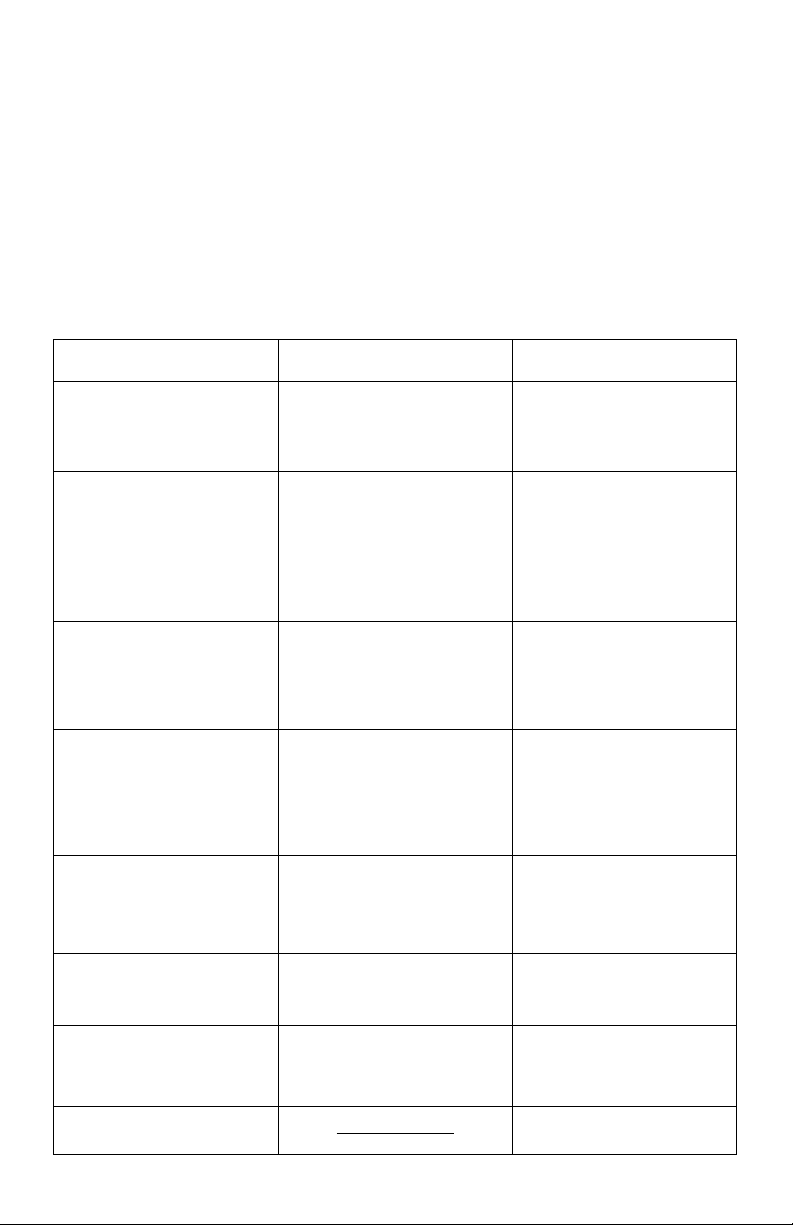
SYMPTOM
Unit will not turn on.
Incorrect weight reading.
Unable to store menu
settings/changes.
RS232 interface not
working (when installed)
Random segments
displayed or display
locks up.
PROBABLE CAUSE(S)
Power adapter not
plugged in or properly
connected to balance.
Balance was not rezeroed before weighing.
Balance not properly
calibrated.
END not being used to
exit menus.
Print menu settings not
properly set up.
Cable connections.
Microprocessor lock up.
REMEDY
Check power adapter
connections.
Press ON TARE with no
weight on the pan, then
weigh item.
Recalibrate correctly.
You MUST use END to
exit menus and save
settings.
Verify interface settings in
Print menu correspond to
those of peripheral device.
Check cable connections.
Unplug the power cord,
then replug again. If
condition persists, unit
must be serviced.
Unable to change
settings.
Unstable readings.
Error message display.
Lock set ON.
Vibration on table
surface.
26
Set Lock switch to OFF.
Place balance on a stable
surface or change
averaging level.
See Error Codes Table.
Page 45

Error CodesError Codes
Error Codes
Error CodesError Codes
The following list describes the various error codes and which can appear on the
display and the suggested remedy.
Data ErrorsData Errors
Data Errors
Data ErrorsData Errors
0.0 Transient error (hardware error, probably static discharge). If error persists,
the balance must be serviced.
Tare ErrorsTare Errors
Tare Errors
Tare ErrorsTare Errors
2.0 Balance is unable to stabilize within time limit after taring. Environment is too
hostile or balance needs recalibration.
Calibration ErrorsCalibration Errors
Calibration Errors
Calibration ErrorsCalibration Errors
3.0 Incorrect or no calibration weight used for calibration. Recalibrate with correct
weights.
RS232 ErrorsRS232 Errors
RS232 Errors
RS232 ErrorsRS232 Errors
4.0 Bad RS232 frame. Check RS232 menu parameters and correct.
4.4 RS232 buffer is full (if installed). May occur if no printer or computer is
connected to the interface. To clear buffer, turn balance off or enter Print menu
and select END.
4.5 Function is disabled by the Lock switch.
User ErrorsUser Errors
User Errors
User ErrorsUser Errors
7.2 Number outside of display capacity.
Over-Under Load ErrorsOver-Under Load Errors
Over-Under Load Errors
Over-Under Load ErrorsOver-Under Load Errors
8.0 Hardware error causing an internal weight signal which is too low. Check if pan
or pan support is off. If not, the balance must be serviced.
8.1 Hardware error caused by an internal weight signal which is too high. Check
load on the platform which may be excessive. If error persists, the balance
must be serviced.
8.2 Power-on load out of specification: Balance was turned on with load on pan or
pan off balance. No load may be on pan when turned on and pan must be in
place.
8.3 Rated capacity exceeded. Remove excessive weight from pan.
8.4 Underload condition on balance. Check that the proper pan and pan support
are installed.
27
Page 46

Error Codes (Cont.)Error Codes (Cont.)
Error Codes (Cont.)
Error Codes (Cont.)Error Codes (Cont.)
CheckSum ErrorsCheckSum Errors
CheckSum Errors
CheckSum ErrorsCheckSum Errors
9.0 Bad factory checksum. If error persists, have the balance serviced.
9.5 Bad factory calibration checksum. If error persists, have the balance serviced.
9.6 Bad mode checksum. Turn the balance off using the front panel controls. If
the error persists, have the balance serviced.
9.7 Invalid setup data checksum. Check Setup, User and Print menu (when
RS232 is installed) settings. If possible, try to enter menus and exit using END
to restore menu settings. May be caused by a faulty component, or in rare
cases, a severe static charge. If error persists, balance must be serviced.
9.8 Hardware error causing invalid calibration data checksum. Balance may need
recalibration - particularly linearity calibration. If error persists, balance must be
serviced.
9.9 Invalid temperature compensation checksum. Balance will work with default
temperature compensation data, however, error will occur each time balance
is turned on. Have balance serviced.
SERVICE INFORMATIONSERVICE INFORMATION
SERVICE INFORMATION
SERVICE INFORMATIONSERVICE INFORMATION
If the Troubleshooting section does not resolve or describe your problem, you will
need to contact an authorized Ohaus Service Agent. For Service assistance in the
United States, please call Ohaus Corporation toll-free at (800) 526-0659, an Ohaus
Product Service Specialist will be available to help you.
28
Page 47
MODELMODEL
MODEL
MODELMODEL
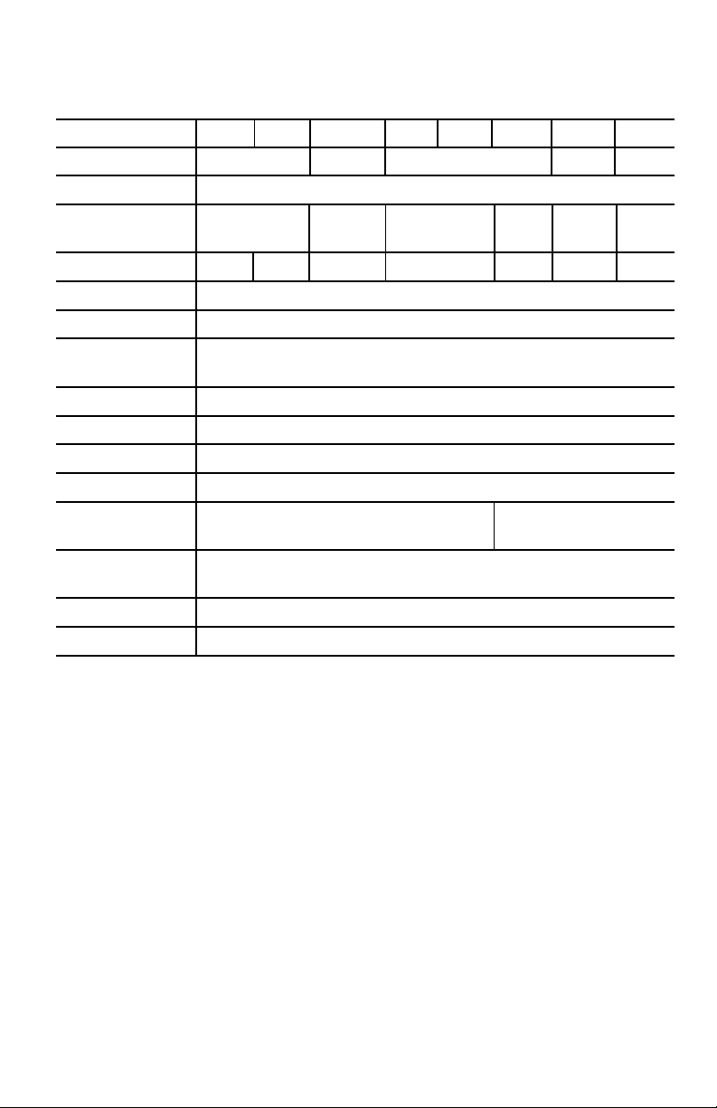
Capacity (g) 120 200 400/80 400 600 2000 4000/800 4000
Readability (g) 0.001 0.01/0.001 0.01 0.1/0.01 0.1
Weighing mode g, lb, oz, lb:oz, ct, dwt, taels, oz t, gn, momme
Repeatability 0.001 0.007/0.001 0.007 0.01 0.07/0.01 0.07
(Std. dev.) (g)
Linearity (g) ±0.001 ±0.002 ±0.01/0.001 ±0.01 ±0.02 ±0.1/0.01 ±0.1
Tare range Full capacity by subtraction
Stabilization time 2.5 seconds
Sensitivity drift
(10 - 30 °C) 10ppm/ °C
Operating temperature 50° to 104°F/10 ° to 40°C
Calibration External digital calibration
Display (in/cm) LCD (0.6/1.5 high)
Power requirements AC adapter: 100, 120, 220, 240 V ac, 50/60 Hz
Platform size (WxHxD) 4.8/ 6 x 6.5/
(in/cm) 12.2 15.2 x 16.5
Dimensions 8 x 3.75 x 14/20.3 x 9.5 x 35.6
(W x H x D) (in/cm) without draft shield
Net weight (lb/kg) 9.8/4.4
Shipping weight (lb/kg) 13.6/6.2
TS120 TS200 TS120 TS200
TS120 TS200
TS120 TS200 TS120 TS200
TS400D TS400D
TS400D
TS400D TS400D
TS400 TS600 TS400 TS600
TS400 TS600
TS400 TS600 TS400 TS600
TS2K TS4KD TS2K TS4KD
TS2K TS4KD
TS2K TS4KD TS2K TS4KD
TS4K TS4K
TS4K
TS4K TS4K
29
Page 48

PARTS INFORMATIONPARTS INFORMATION
PARTS INFORMATION
PARTS INFORMATIONPARTS INFORMATION
If you require replacement parts or would like to purchase accessories, please call
Ohaus Corporation toll-free at (800) 526-0659, an Ohaus Product Parts Specialist will
be available to help you.
REPLACEMENT PARTSREPLACEMENT PARTS
REPLACEMENT PARTS
REPLACEMENT PARTSREPLACEMENT PARTS
OHAUS
Description Part No.
AC Adapters:
100V 90766-01
120V 90765-01
220V 90767-01
240V 90768-01
240V Australia 90524-15
Pan - 4.7” dia. 77262-10
Pan - 6.0” x 6.5” 77298-10
Draft Shield Snap Clamp (TS120, TS200 and TS400D) 77334-00
ACCESSORIESACCESSORIES
ACCESSORIES
ACCESSORIESACCESSORIES
OHAUS
Part No.
In-Service Cover 78211-02
Draft Shield Kit 76934-03
Chamber Size: 6.0”W x 4.25”H x 6.375”D
RS232 Interface Kit 77018-01
Cable for RS232 Interface AS020-17
Cable with PRINT switch for RS232 Interface AS017-25
Leveling Foot Conversion Kit: 77327-00
Weigh Below Hook 76790-00
Security Device 76288-01
Calibration Masses - ASTM Class 1 Tolerance:
50g 49054-11
100g 49015-11
200g 49025-11
400g 49045-11
500g 49055-11
1kg 49016-11
2kg 49026-11
4kg 49046-11
30
Page 49

LIMITED WARRANTY LIMITED WARRANTY
LIMITED WARRANTY
LIMITED WARRANTY LIMITED WARRANTY
Ohaus products are warranted against defects in materials and
workmanship from the date of delivery through the duration of the
warranty period. During the warranty period Ohaus will repair, or, at
its option, replace any component(s) that proves to be defective at no
charge, provided that the product is returned, freight prepaid, to
Ohaus.
This warranty does not apply if the product has been damaged by
accident or misuse, exposed to radioactive or corrosive materials,
has foreign material penetrating to the inside of the product, or as a
result of service or modification by other than Ohaus. In lieu of a
properly returned warranty registration card, the warranty period shall
begin on the date of shipment to the authorized dealer. No other
express or implied warranty is given by Ohaus Corporation. Ohaus
Corporation shall not be liable for any consequential damages.
As warranty legislation differs from state to state and country to
country, please contact Ohaus or your local Ohaus dealer for further
details.
31
Page 50

Ohaus Corporation
29 Hanover Road,
Florham Park, NJ 07932, USA
Tel: (973) 377-9000,
Fax: (973) 593-0359
With offices worldwide.
P/N 77331-04 © Ohaus Corporation 1997, 1999 all rights reserved.
32
Page 51

Weigh Below Hook
Accessor y
P/N 76790-00
INSTALLATIONINSTALLATION
INSTALLATION
INSTALLATIONINSTALLATION
1. Turn the balance OFF.
2. Remove the pan.
3. Hold the pan support in place and
turn the balance over or on its side.
4. Screw the hook into the threaded
hole in the pan support which is
visible through the access hole in the
bottom of the balance.
BOTTOM OF
PAN SUPPORT
For PRECISION
Standard
Electronic Balances
Installation InstructionsInstallation Instructions
Installation Instructions
Installation InstructionsInstallation Instructions
© Ohaus Corporation 1991, all rights reserved.
5. Replace the pan.
OHAUS® is the registered trademark of Ohaus Corporation as are the following
trademarks: AUTOGRAM® , BRAINWEIGH® , CENT-O-GRAM® , CHECK-O-GRAM® ,
CUBE-O-GRAM® , DEC-O-GRAM® , DIAL-O-GRAIN® , DIAL-O-GRAM® , DU-O-MEASURE® , GALAXY® , LUME-O-GRAM® , PORT-O-COUNT® , PORT-O-GRAM® , PRACTO-GRAM® , PRIMER® , STO-A-WEIGH® , TOUCH-N-WEIGH® , 5-0-5® , and 10-10® .
OHAUS CORPORATIONOHAUS CORPORATION
OHAUS CORPORATION
OHAUS CORPORATIONOHAUS CORPORATION
P.O. Box 900 Broad Lane, Cottenham
29 Hanover Road Cambridge CB4 4SW
Florham Park, N.J. 07932 ENGLAND
Tel: 201-377-9000 Tel: 0954-51343
Telex: 6853191 OHAUS UW Telex: 817285 OSCALE G
Fax: 201-593-0359 Fax: 0954-50205
OHAUS EUROPE, LTD.OHAUS EUROPE, LTD.
OHAUS EUROPE, LTD.
OHAUS EUROPE, LTD.OHAUS EUROPE, LTD.
P/N 77332-00
Page 52
Draft Shield
Accessor y Kit
P/N 76934-01
For PRECISION
Electronic Balances
Models TS400, TP400 and TP600
Standard
and
Plus
UNPACKINGUNPACKING
UNPACKING
UNPACKINGUNPACKING
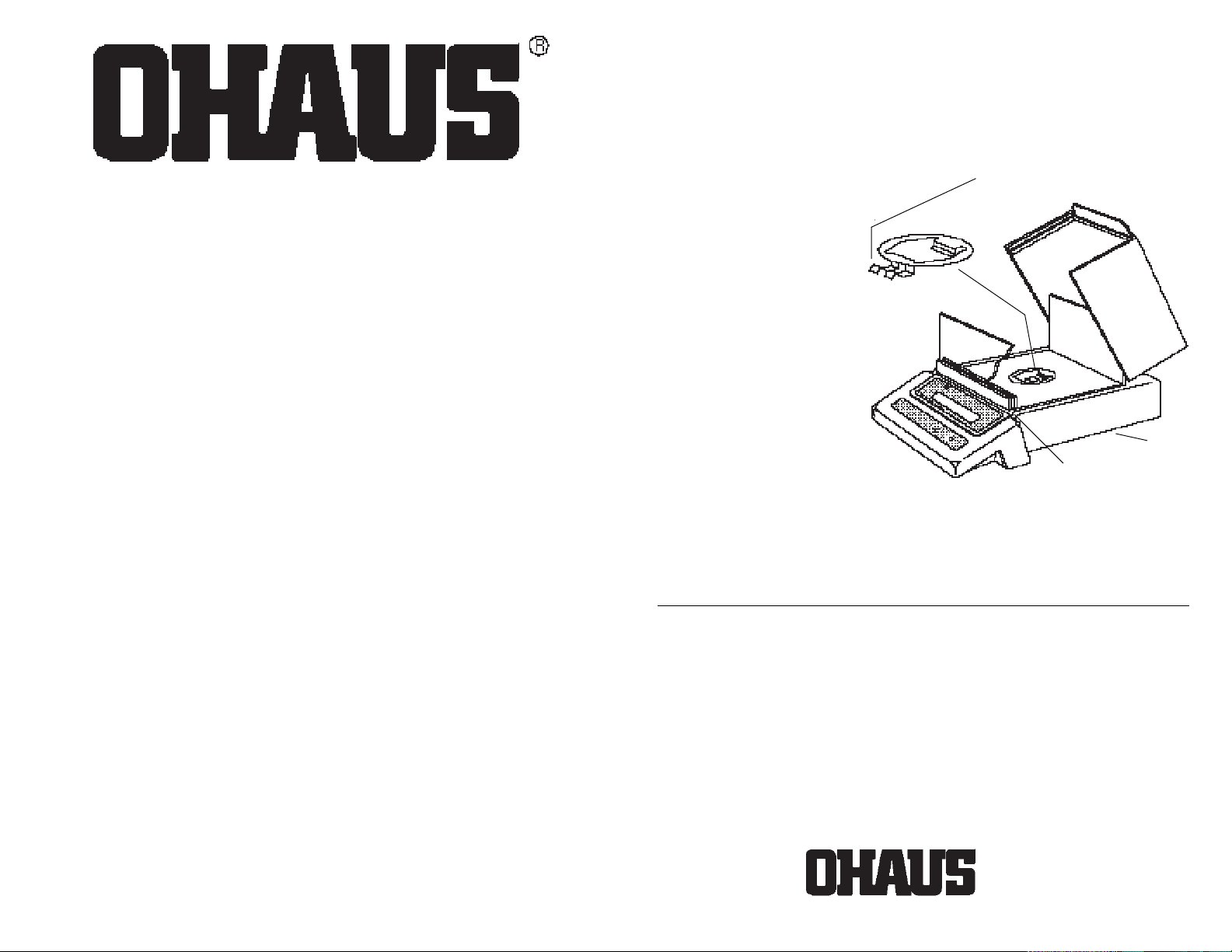
Verify that a Draft Shield and Snap Clamp
have been included in the kit.
INSTALLATIONINSTALLATION
INSTALLATION
INSTALLATIONINSTALLATION
1. Remove the pan and pan support.
2. Position the draft shield
on top of the balance as
shown. Make sure the rib
at the front of the draft
shield base butts up
against the raised lip of the
display panel.
3. The snap clamp should be
oriented so that the double
clip is toward the front of
the balance.
First, insert the double clip
end of the snap clamp fully into
the opening towards the front of the
draft shield base and the underside of
the cover. Next, press the rear clip of the
snap clamp down into place.
Double
Clip
Snap
Clamp
Cover
Position rib up against
display panel.
Installation InstructionsInstallation Instructions
Installation Instructions
Installation InstructionsInstallation Instructions
© Ohaus Corporation 1993, all rights reserved.
4. Replace the pan and pan support.
OHAUS® is the registered trademark of Ohaus Corporation as are the following
trademarks: CENT-O-GRAM® , CHECK-O-GRAM® , DEC-O-GRAM® , DIAL-O-GRAM
PRIMER® , 5-0-5® , and 10-10® .
OHAUS CORPORATIONOHAUS CORPORATION
OHAUS CORPORATION
OHAUS CORPORATIONOHAUS CORPORATION
P.O. Box 900
29 Hanover Road
Florham Park, N.J. 07932, USA
Tel: 201-377-9000
Telex: 6853191 OHAUS UW
Fax: 201-593-0359
With other offices in England, Mexico, Canada,
Japan, Germany, France, Switzerland
®
,
®
P/N 77326-01 R0793
Page 53

Ohaus Corporation
29 Hanover Road
Florham Park NJ
07932-0900
Leveling Kit Accessory
P/N 77327-00
For PRECISION
Standard
Electronic Balances
Installation Instructions
UNPACKING
The Leveling Kit includes the following components:
1 FCC label 1 level assembly with
2 lockwashers 3 set screws installed
2 phillips screws 1 brass foot
4 leveling feet (2 pairs)
© Ohaus Corporation 1991, 1999, all rights reserved.
Page 54
INSTALLATIONINSTALLATION
INSTALLATION
INSTALLATIONINSTALLATION
A phillips screwdriver, 1/16” hex wrench
and 9/64” hex wrench will be required to
install the leveling kit.
1. Disconnect power to the balance.
2. Remove the pan and pan support.
3. Turn the balance over.
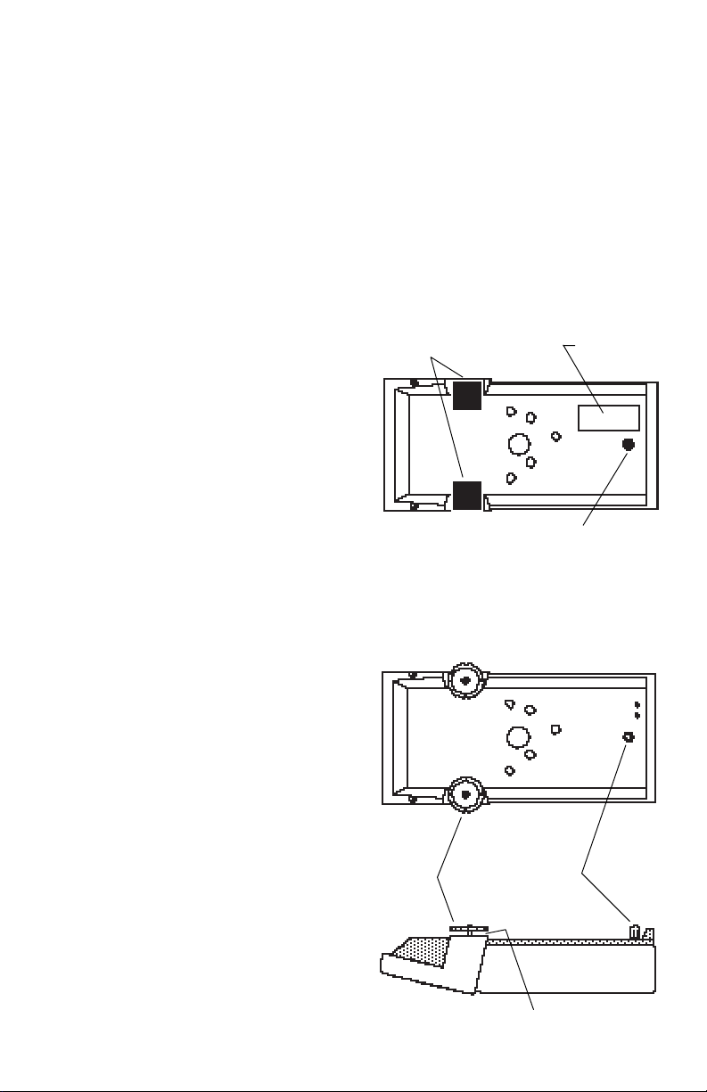
4. Remove the FCC label. The label
covers two clearance holes that will
be used for mounting the leveling
assembly.
5. Peel off the two rubber feet at the front
of the balance.
6. Using a 9/64” hex wrench, remove
the socket head screw at the rear of
the balance. Leave the washer in
place.
7. Install the brass foot in place of the
socket head screw.
8. Screw the leveling feet in leaving
approximately 3/16” clearance between the bottom of the balance and
the foot.
NOTE: Two pairs of leveling feet are included in this kit. The all plastic feet are
for earlier TS Models. The leveling feet
with metal threaded shafts are for later
versions.
Rubber Feet
Leveling
Feet
FCC Label
Socket head
Screw
Brass
Foot
3/16” Clearance
2
Page 55
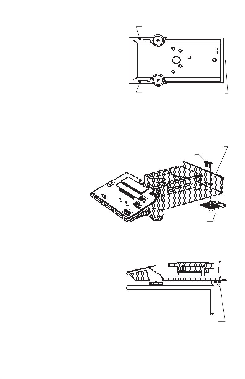
9. Remove the three phillips head
screws which secure the balance
cover to the base.
10. Hold the base and cover together
and turn the balance right side up.
11. Lift the cover off.
Remove
12. Using the two phillips screws and
lockwashers provided in the kit, fasten the leveling assembly as shown
in the diagram.
Screws should be snug but not tight.
DO NOT COMPLETELY TIGHTEN
THE SCREWS.
13. Place the balance on a level work
surface. ENSURE SURFACE IS
LEVEL BEFORE CONTINUING. Position the balance so that the leveling
assembly extends from the edge of
the work surface.
Remove
Phillips Screws
Remove screw
on rear panel
(not shown)
Lockwashers
Leveling
Assembly
14. Using a 1/16” hex wrench adjust the
three set screws in the leveling assembly as needed to center the
bubble in the level indicator.
When the bubble is centered, tighten
the two phillips screws.
15. Apply the new FCC label (included in
the kit) to the bottom of the balance.
Do not to cover any screws or holes.
Adjust set screws as needed
3
Page 56

16. Replace the cover and fasten with the
three phillips screws that were removed in step 9.
17. Replace the pan support and pan.
18. Place the balance in the location
where it will be used and verify it is
level. If minor adjustment is needed, use the leveling feet.
19. Recalibrate the balance as explained in the instruction manual supplied with the
balance.
Ohaus Corporation
29 Hanover Road,
Florham Park, NJ 07932, USA
Tel: (973) 377-9000,
Fax: (973) 593-0359
With offices in England, Germany, France, Spain, Italy, Poland, Mexico, Japan,
Korea and China.
P/N 77328-00 R0699
Page 57
Ohaus Corporation
29 Hanover Road
Florham Park NJ
07932-0900
In-Service Cover
Accessory Kit
P/N 76901-30
For PRECISION
Electronic Balances
Installation InstructionsInstallation Instructions
Installation Instructions
Installation InstructionsInstallation Instructions
Standard
and
Plus
UNPACKINGUNPACKING
UNPACKING
UNPACKINGUNPACKING
The kit includes a cover and one adhesive pad.
INSTALLATIONINSTALLATION
INSTALLATION
INSTALLATIONINSTALLATION
1. Remove the pan and
pan support from the
balance.
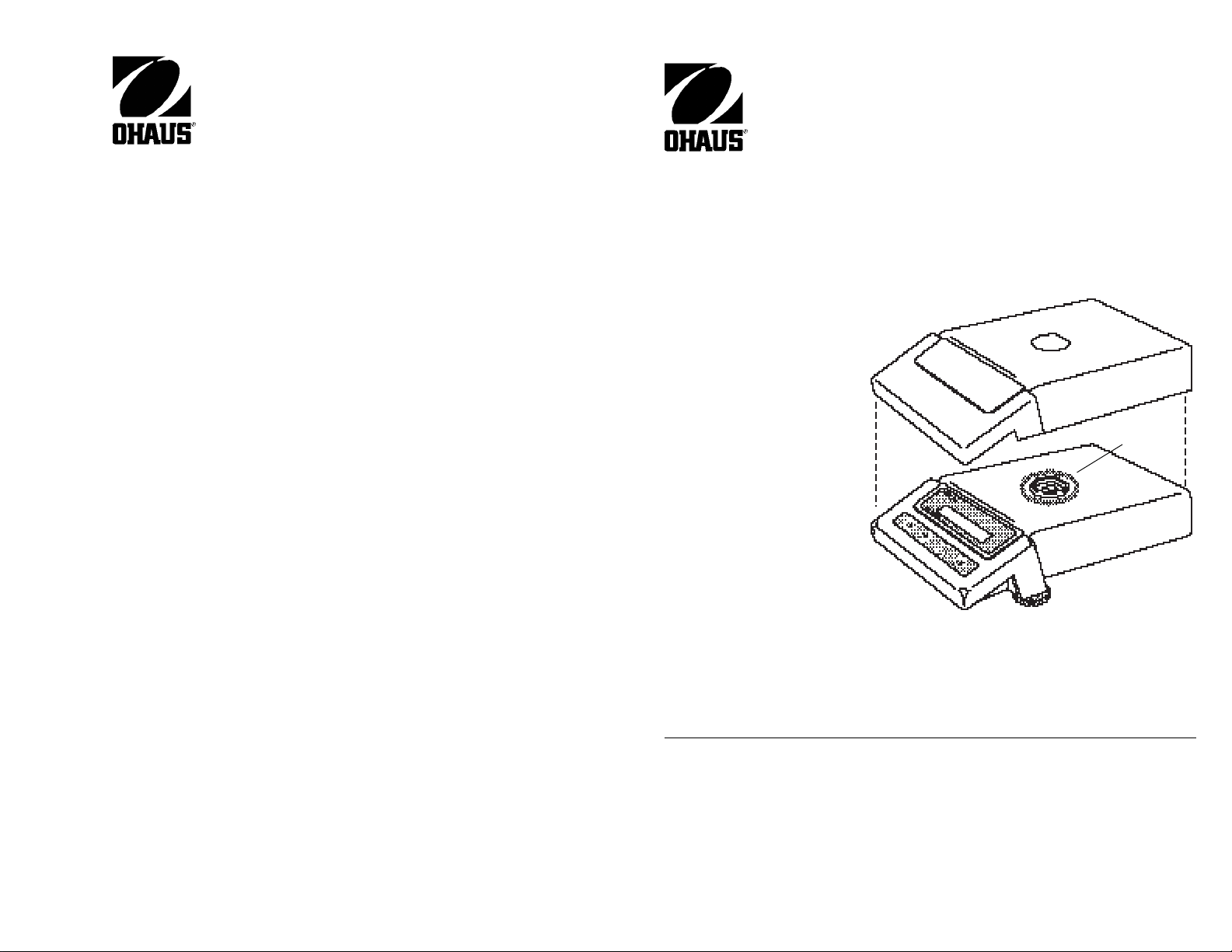
2. Place the cover over the
balance as shown in the
diagram. If desired, the
adhesive pad may be
used to secure the cover
to the balance to avoid
possible movement.
Peel the backing off of
one side of the adhesive pad, center adhesive pad over hole in
top cover and press the
pad onto the top of the
balance as shown in the
diagram.
COVER
ADHESIVE
PAD
© Ohaus Corporation 1996, 1998 all rights reserved.
Remove the backing from the top of the pad, place the cover on the balance and
press down on the pad.
3. Replace the pan and pan support.
Ohaus Corporation
29 Hanover Road,
Florham Park, NJ 07932, USA
Tel: (973) 377-9000,
Fax: (973) 593-0359
With offices in England, Germany, France, Spain, Italy, Poland, Mexico,
Japan, Korea and China.
P/N 76902-30 R1198
Page 58

Ohaus Corporation
29 Hanover Road
Florham Park NJ
07932-0900
RS232 INTERFACE ACCESSORY
Part Number 77018-01
For
ANALYTICAL
and
PRECISION
Standard
Standard
Series
Balance Series
Instruction Manual
1
Page 59

NOTICE:NOTICE:
NOTICE: THIS EQUIPMENT HAS BEEN TESTED AND FOUND TO
NOTICE:NOTICE:
COMPLY WITH THE LIMITS FOR A CLASS A DIGITAL DEVICE, PURSUANT TO PART 15 OF THE FCC RULES.
THESE LIMITS ARE DESIGNED TO PROVIDE REASONABLE PROTECTION AGAINST HARMFUL INTERFERENCE WHEN THE
EQUIPMENT IS OPERATED IN A COMMERCIAL ENVIRONMENT.
THIS EQUIPMENT GENERATES, USES, AND CAN RADIATE RADIO
FREQUENCY ENERGY AND, IF NOT INSTALLED AND USED IN ACCORDANCE WITH THE INSTRUCTION MANUAL, MAY CAUSE
HARMFUL INTERFERENCE TO RADIO COMMUNICATIONS. OPERATION OF THIS EQUIPMENT IN A RESIDENTIAL AREA IS LIKELY
TO CAUSE HARMFUL INTERFERENCE IN WHICH CASE THE USER
WILL BE REQUIRED TO CORRECT THE INTERFERENCE AT HIS
OWN EXPENSE.
THIS DIGITAL APPARATUS DOES NOT EXCEED THE CLASS A LIMITS FOR RADIO NOISE EMISSIONS FROM DIGITAL APPARATUS AS
SET OUT IN THE INTERFERENCE-CAUSING EQUIPMENT STANDARD ENTITLED “DIGITAL APPARATUS”, ICES-003 OF THE
DEPARTMENT OF COMMUNICATIONS.
CET APPAREIL NUMERIQUE RESPECTE LES LIMITES DE BRUITS
RADIOELECTRIQUES APPLICABLES AUX APPAREILS NUMERIQUES
DE CLASSE A PRESCRITES DANS LA NORME SUR LE MATERIEL
BROUILLEUR : “APPAREILS NUMERIQUES”, NMB-003 EDICTEE PAR
LE MINISTRE DES COMMUNICATIONS.
Unauthorized changes or modifications to this equipment are not
permitted.
2
Page 60

TABLE OF CONTENTSTABLE OF CONTENTS
TABLE OF CONTENTS
TABLE OF CONTENTSTABLE OF CONTENTS
INTRODUCTION .................................................................................................. 4
INSTALLATION .................................................................................................... 4
USING MENUS TO CONFIGURE THE BALANCE ............................................. 6
PRINT MENU ....................................................................................................... 7
Print Menu Protection.................................................................................... 7
Reset to Factory Defaults.............................................................................. 8
Baud Rate ..................................................................................................... 9
Data Bits........................................................................................................ 9
Parity ........................................................................................................... 10
Stop Bits ...................................................................................................... 10
Auto Print Feature ....................................................................................... 11
Print Stable Data Only................................................................................. 11
Print Numeric Data Only ............................................................................. 12
End .............................................................................................................. 12
MENU LOCK-OUT PROTECTION..................................................................... 13
USING THE INTERFACE .................................................................................. 14
Hardware..................................................................................................... 14
RS232 Commands ...................................................................................... 14
CARE AND MAINTENANCE.............................................................................. 17
TROUBLESHOOTING ....................................................................................... 17
Error Codes ................................................................................................. 17
SERVICE INFORMATION ................................................................................. 17
LIMITED WARRANTY........................................................................................ 19
3
Page 61
INTRODUCTIONINTRODUCTION
INTRODUCTION
INTRODUCTIONINTRODUCTION
The RS232 Interface Accessory is a
bidirectional interface which enables either a Precision Standard or an Analytical
Standard balance to communicate with a
printer or computer equipped with an
RS232 serial port. The interface assembly
is easily installed in the balance and communication parameters are configured
through the balance’s front panel.
INSTALLATIONINSTALLATION
INSTALLATION
INSTALLATIONINSTALLATION
Use the following procedure to install the
RS232 Interface accessory.
CAUTIONCAUTION
CAUTION
CAUTIONCAUTION
TO PREVENT DAMAGE TO THE BALANCE, BE CERTAIN THAT POWER IS
DISCONNECTED BEFORE REMOVING
THE COVER.
1. Disconnect power to the balance.
2. Remove the draft shield (if installed).
3. Remove the pan and pan support.
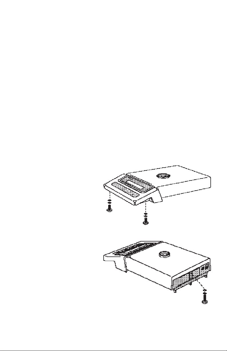
4. Using a philips screwdriver, remove the three screws and washers
which secure the cover to the balance. The balance will have to be
turned over or on its side to access
the screws as they are located
on the bottom; two under the
front panel and one on the rear.
CAUTIONCAUTION
CAUTION
CAUTIONCAUTION
HOLD THE COVER AND BASE TOGETHER WHILE REMOVING SCREWS.
DO NOT ALLOW COVER OR BASE TO
FALL.
4
Page 62
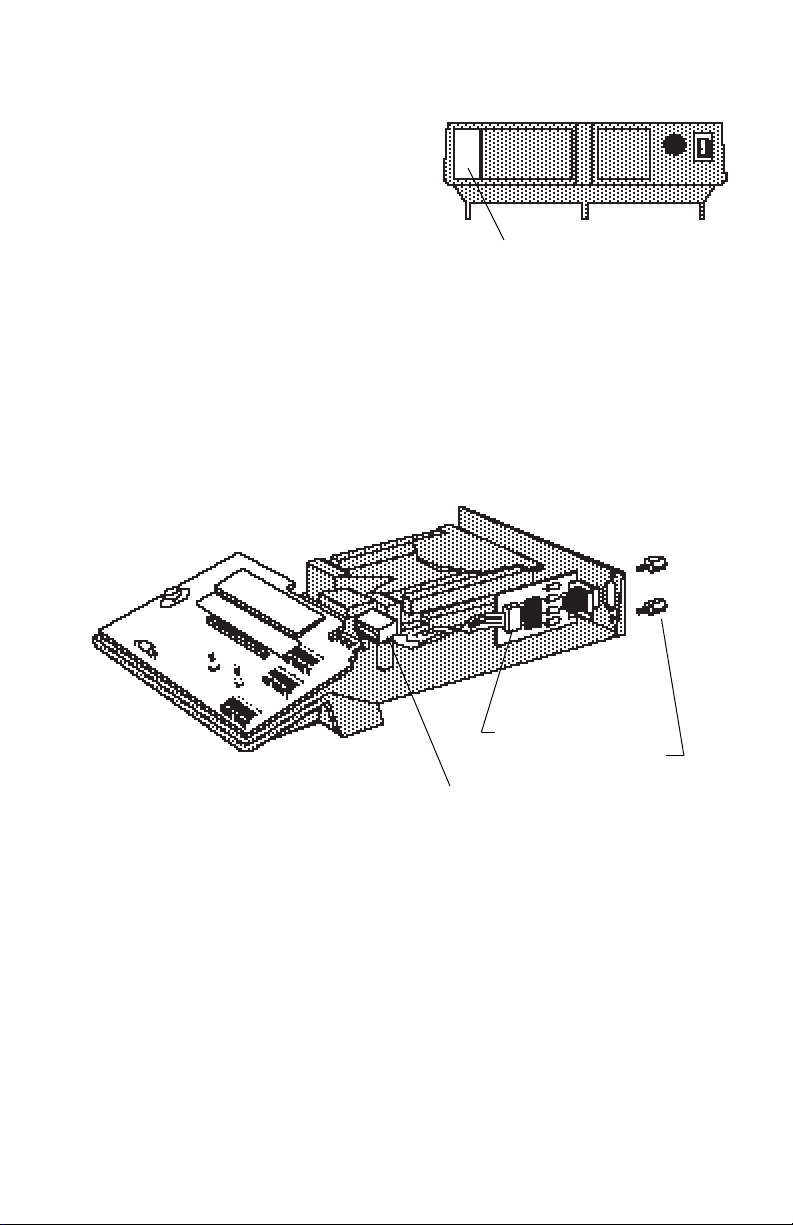
5. Remove the cover.
6. On the rear of the balance, a protective thin plate covers the hole for the
9-pin RS232 connector.
Peel off the plate to expose the hole.
7. Place the circuit board and connector
assembly in the balance so that the 9pin connector fits through the hole.
8. Fasten the assembly using the two
screws provided.
9. Slide the ribbon connector onto the
edge connector of the main circuit
board.
10. Replace the cover and fasten the
three screws that were removed.
11. Replace the draft shield.
Ribbon
Connector
Remove Plate
RS232
Circuit
Board
Fasten
Screws
12. Replace the pan and pan support.
13. Reconnect power to the balance.
5
Page 63
USING MENUS TO CONFIGURE THE BALANCEUSING MENUS TO CONFIGURE THE BALANCE
USING MENUS TO CONFIGURE THE BALANCE
USING MENUS TO CONFIGURE THE BALANCEUSING MENUS TO CONFIGURE THE BALANCE
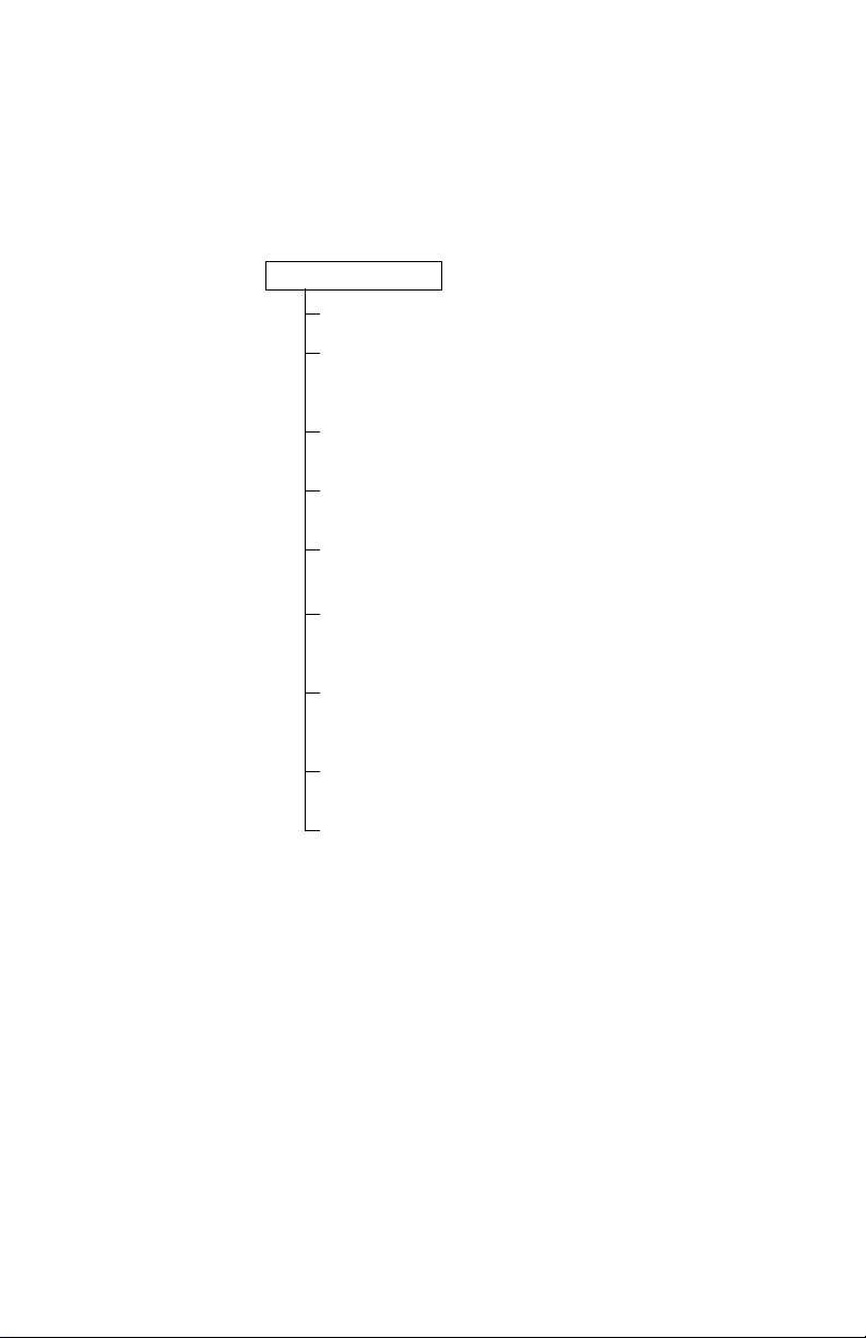
The Analytical Standard and Precision Standard balances both contain four display
menus which enable you to calibrate and configure the balance for your specific
operating requirements. The print menu shown below is used to configure the RS232
interface.
PRINT MENU
RESET
BAUD RATE
300, 1200,
4800, 9600
24002400
2400,
24002400
DATA BITS
77
7 or 8
77
PARITY BIT
Odd, Even,
NoneNone
None, 1, 0
NoneNone
STOP BITS
22
1 or
2
22
AUTO PRINT
continuous, on stability,
OFFOFF
OFF
OFFOFF
STABLE DATA OUTPUT ONLY
OFFOFF
ON or
OFF
OFFOFF
NUMERIC DATA OUTPUT ONLY
OFFOFF
ON or
OFF
OFFOFF
END
6
Page 64
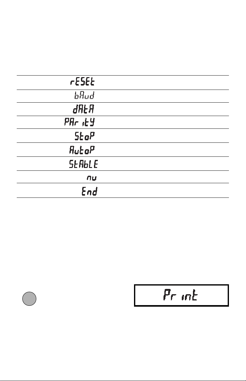
PRINT MENUPRINT MENU
PRINT MENU
PRINT MENUPRINT MENU
When the interface is installed, the Print menu is used to configure the RS232 interface
parameters and customize the balance’s print functions for your requirements. The
following table shows the sequence in which submenus appear on the Print menu.
PRINT MENU TABLEPRINT MENU TABLE
PRINT MENU TABLE
PRINT MENU TABLEPRINT MENU TABLE
*
Sets all submenus below to original factory
default settings.
Specifies baud rate.
Specifies number of data bits.
Specifies parity type, if any.
Specifies number of stop bits.
Enables/disables Auto print feature.
Enables/disables printing stable-data-only
feature.
Specifies numeric-only or full display data
for output.
Used to exit the Print menu and store your
selections.
* Does not appear in menu if menu is locked out.
Print Menu ProtectionPrint Menu Protection
Print Menu Protection
Print Menu ProtectionPrint Menu Protection
The Print menu may be locked out to
prevent unauthorized personnel from
changing settings. To lock out the print
menu, refer to the section titled Menu
Lock-Out-Protection.
To access the Print menu press and hold
ONON
ON
ONON
until PRINT is displayed, then re-
TARETARE
TARE
TARETARE
lease it.
If SAFE is displayed, the Print menu has
been locked-out. Settings may be viewed
but not changed. See the Menu Lock-Out
Protection section to enable it for making
changes.
7
Page 65
To access a submenu:
OFFOFF
OFF
1. Repeatedly press
OFFOFF
until the de-
MODEMODE
MODE
MODEMODE
sired submenu is displayed.
ONON
ON
ONON
TARETARE
TARE
TARETARE
2. Press
to select the displayed
submenu.
NOTE:NOTE:
NOTE: You must use END to store any
NOTE:NOTE:
changes you make to the Print menu.
The following sections describe each item
on the Print menu in detail.
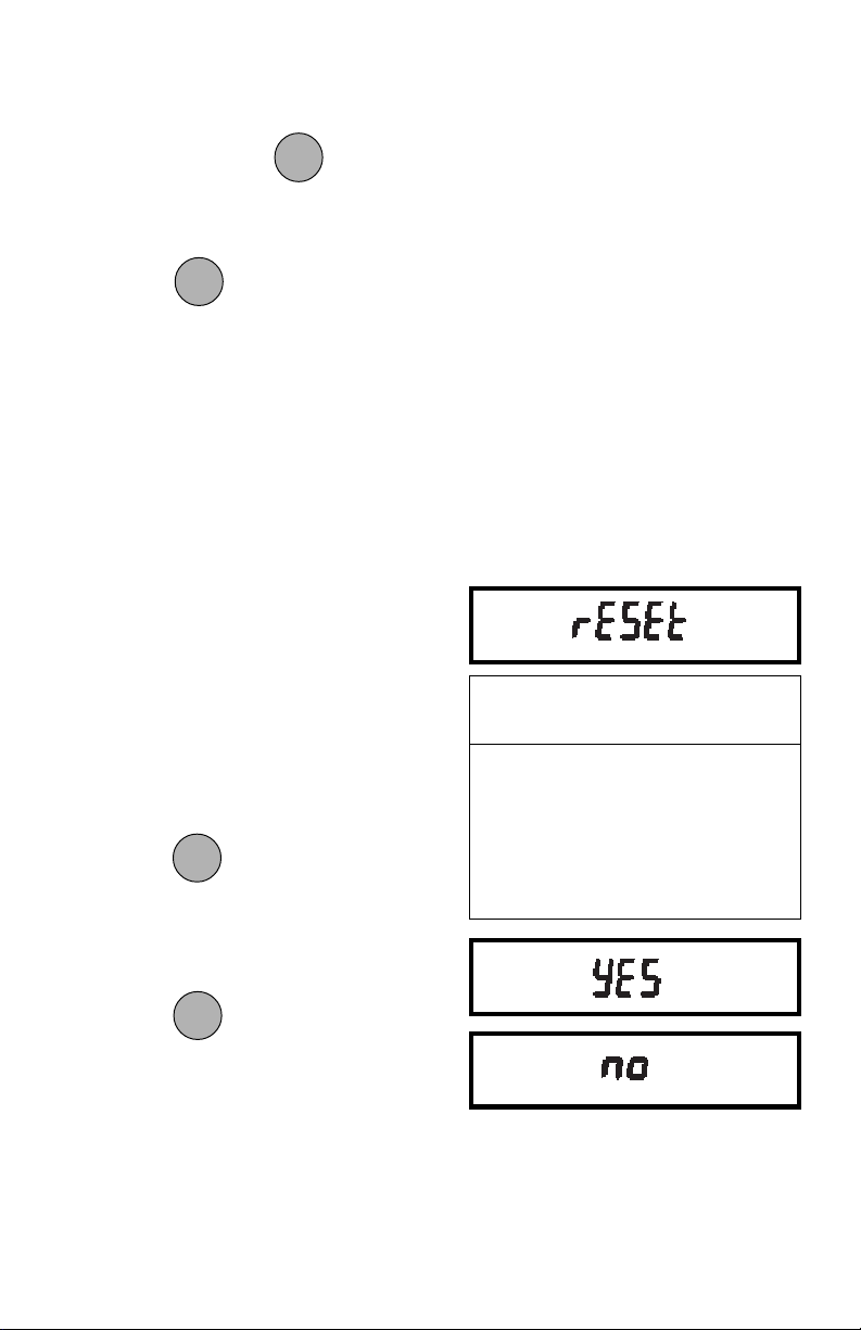
Reset to Factory DefaultsReset to Factory Defaults
Reset to Factory Defaults
Reset to Factory DefaultsReset to Factory Defaults
This submenu enables you to reset all
RS232 menu selections to the original
factory default settings outlined in the adjacent table.
To reset to factory defaults:
1. Access the Reset submenu to view
the current setting.
OFFOFF
OFF
2. Press
OFFOFF
to change the setting.
MODEMODE
MODE
MODEMODE
(Select YES to reset settings or,
NO to leave current settings.)
PRINT MENUPRINT MENU
PRINT MENU
PRINT MENUPRINT MENU
FACTORY DEFAULTSFACTORY DEFAULTS
FACTORY DEFAULTS
FACTORY DEFAULTSFACTORY DEFAULTS
Baud rate br 2400
Data Bits 7 data
Parity None
Stop Bits 2 stop
Auto Print OFF
Stable Data Only OFF
Numeric Data Only OFF
Press
setting.
ONON
ON
ONON
to accept the displayed
TARETARE
TARE
TARETARE
8
Page 66
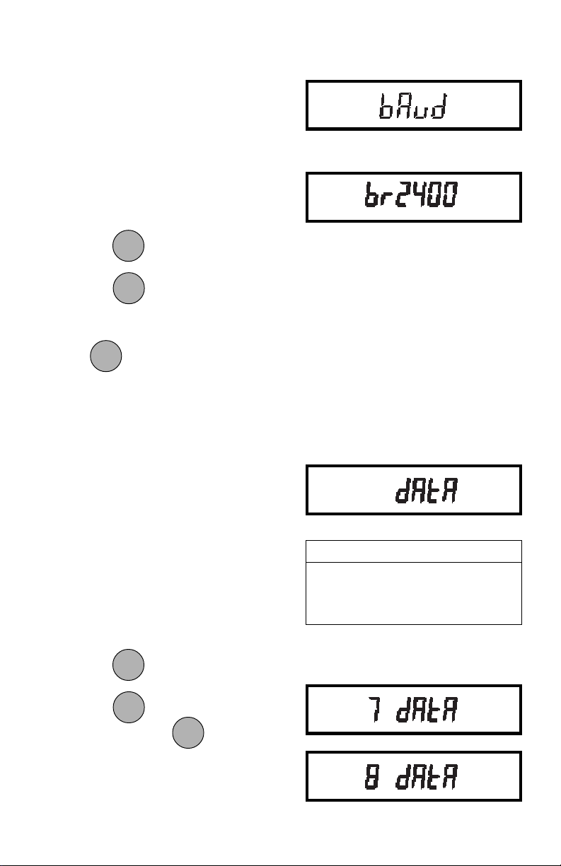
Baud RateBaud Rate
Baud Rate
Baud RateBaud Rate
This submenu is used to select the desired baud rate. There are five available
baud rates to choose from: 300, 1200,
2400, 4800 and 9600.
To view or change the baud rate:
1. Access the Baud submenu to dis-
play the current setting.
OFFOFF
OFF
OFFOFF
Press
MODEMODE
to change the setting.
MODE
MODEMODE
ONON
ON
ONON
to accept the displayed
TARETARE
TARE
TARETARE
2. Press
setting.
ONON
ON
When
ONON
is released, BAUD will be
TARETARE
TARE
TARETARE
displayed again and the Print menu
will be returned.
Data BitsData Bits
Data Bits
Data BitsData Bits
The total number of bits for Data, Parity
and Stop must equal 9 or 10. (see examples). The balance will not permit you
to select a combination that does not equal
9 or 10.
To set the number of data bits to 7 or 8:
1. Access the Data submenu to display
the current setting.
OFFOFF
OFF
2. Press
Press
setting. When is released,
OFFOFF
to change the setting.
MODEMODE
MODE
MODEMODE
ONON
ON
ONON
to accept the displayed
TARETARE
TARE
TARETARE
ONON
ON
ONON
TARETARE
TARE
TARETARE
DATA will be displayed again and the
Print menu will be returned.
EXAMPLESEXAMPLES
EXAMPLES
EXAMPLESEXAMPLES
8 Data + 2 Stop + No Parity = 10
8 Data + 1 Stop + Odd Parity = 10
7 Data + 1 Stop + Odd Parity = 9
9
Page 67
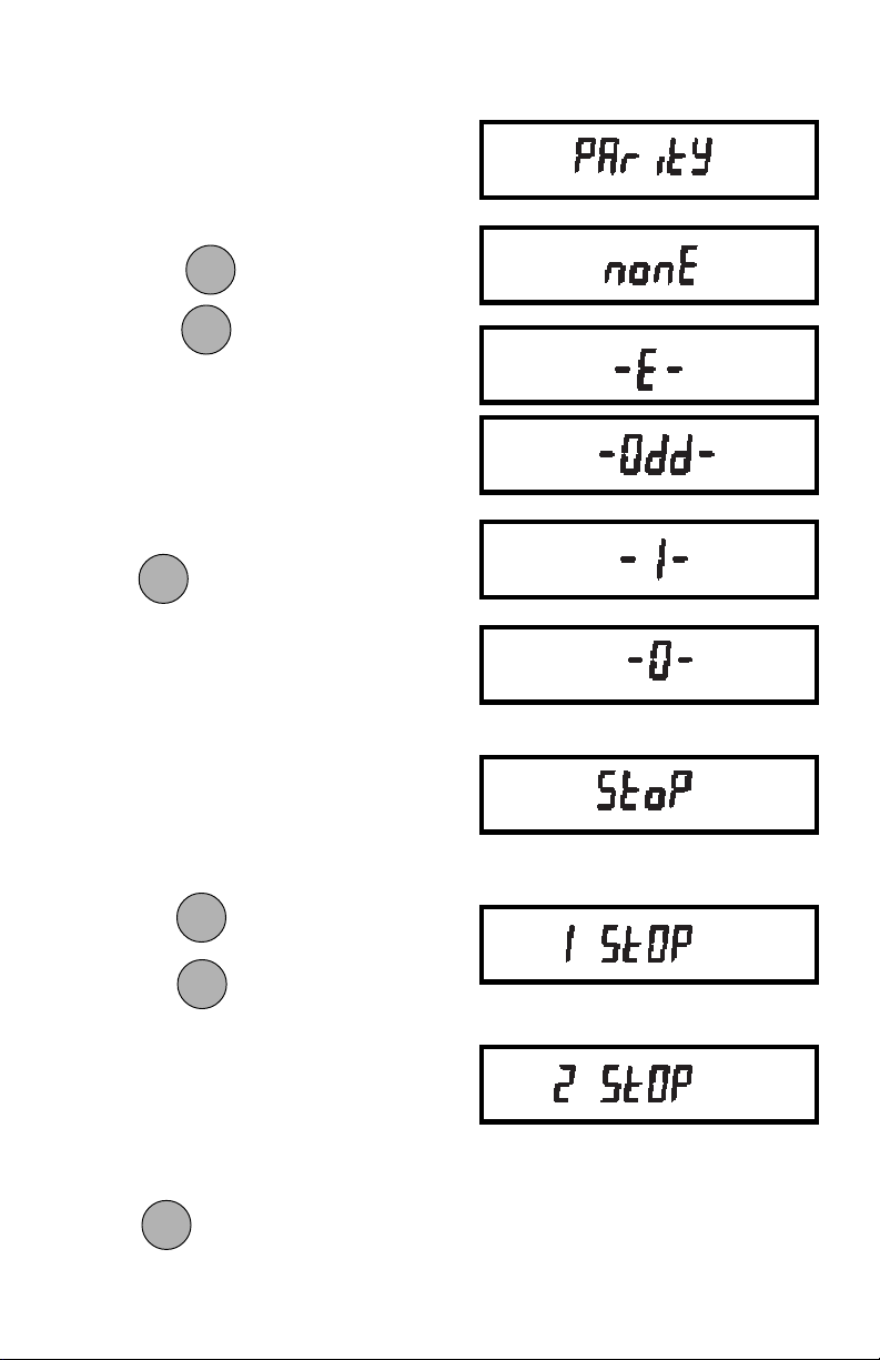
ParityParity
Parity
ParityParity
Parity can be set to Odd, Even, None, or a
marker of 0 or 1 as follows:
1. Access the Parity submenu to display
the current setting.
2. Press
Press to accept the displayed
to change the setting.
MODEMODE
MODE
MODEMODE
ONON
ON
ONON
TARETARE
TARE
TARETARE
setting.
NOTE: NOTE:
NOTE: If all selections do not appear, total
NOTE: NOTE:
number of data, parity and stop bits is
currently < 8 or > 10. Data or stop bits must
be changed.
ONON
ON
When
ONON
is released, PARITY will be
TARETARE
TARE
TARETARE
displayed again and the Print menu will be
returned.
Stop BitsStop Bits
Stop Bits
Stop BitsStop Bits
The number of stop bits can be set to 1 or
2 as follows:
1. Access the Stop submenu to display
the current setting.
MODEMODE
MODE
2. Press to change the setting.
3. Press
MODEMODE
ONON
ON
ONON
to accept the displayed
TARETARE
TARE
TARETARE
setting.
NOTE: NOTE:
NOTE: If all selections do not appear, total
NOTE: NOTE:
number of data, parity and stop bits is
currently < 8 or > 10. Data or parity bits
must be changed.
ONON
ON
When
ONON
is released, STOP will be
TARETARE
TARE
TARETARE
displayed again and the Print menu will be
returned.
10
Page 68
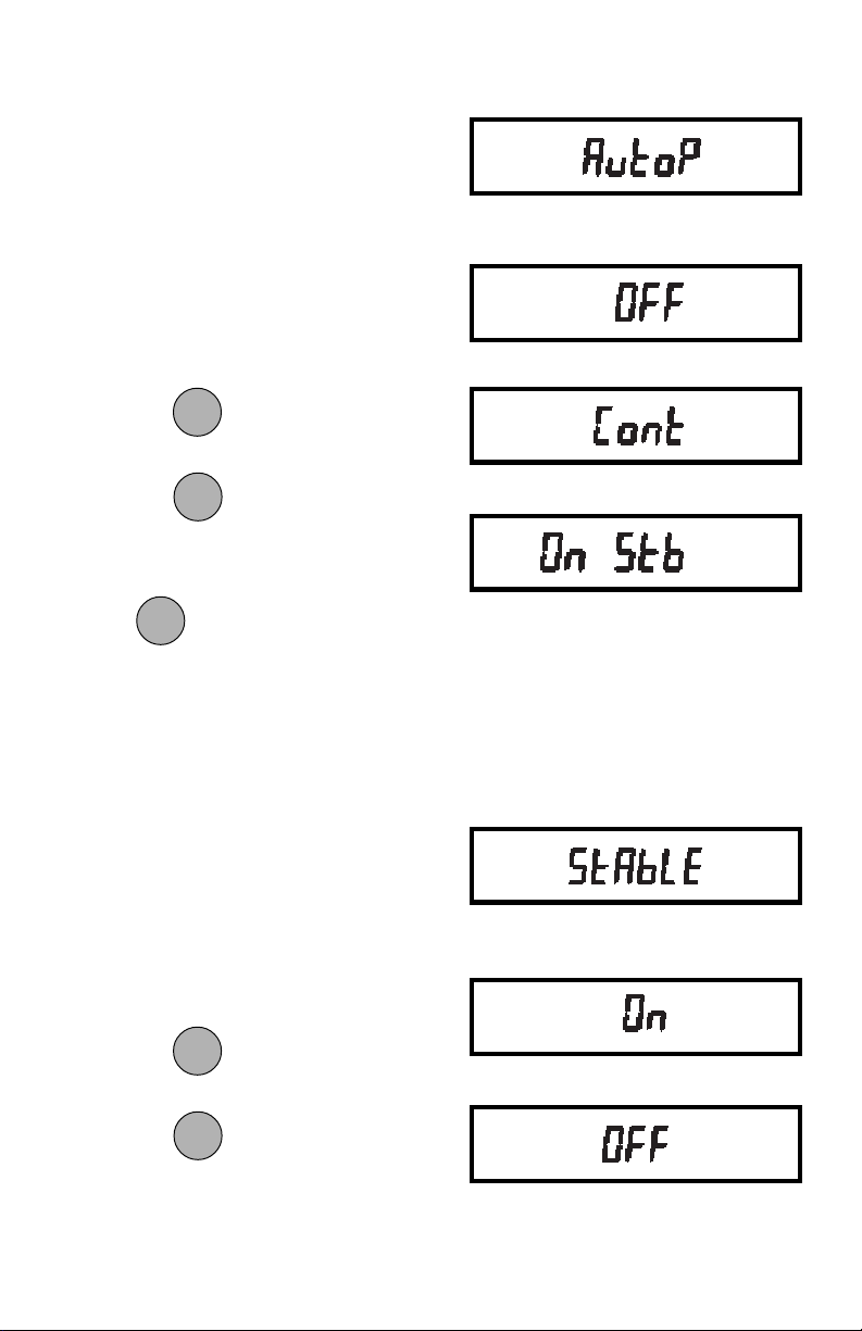
Auto Print FeatureAuto Print Feature
Auto Print Feature
Auto Print FeatureAuto Print Feature
When enabled, the Auto Print feature
causes the balance to automatically output display data in one of two ways: continuously, or upon stability.
To select one of these Auto Print methods,
or to turn the feature off:
1. Access the AutoP submenu to display the current setting.
OFFOFF
OFF
2. Press
Press
OFFOFF
to change the setting.
MODEMODE
MODE
MODEMODE
ONON
ON
ONON
to accept the displayed
TARETARE
TARE
TARETARE
setting.
ONON
ON
When
ONON
is released, AUTOP will be
TARETARE
TARE
TARETARE
displayed again and the Print menu will be
returned.
Print Stable Data OnlyPrint Stable Data Only
Print Stable Data Only
Print Stable Data OnlyPrint Stable Data Only
.
When enabled, this feature permits only
stable display data to be output. To set the
feature ON or OFF:
1. Access the Stable submenu to display the current status.
OFFOFF
OFF
OFFOFF
2. Press
Press
to change the status.
MODEMODE
MODE
MODEMODE
ONON
ON
ONON
to accept the displayed
TARETARE
TARE
TARETARE
status.
11
Page 69
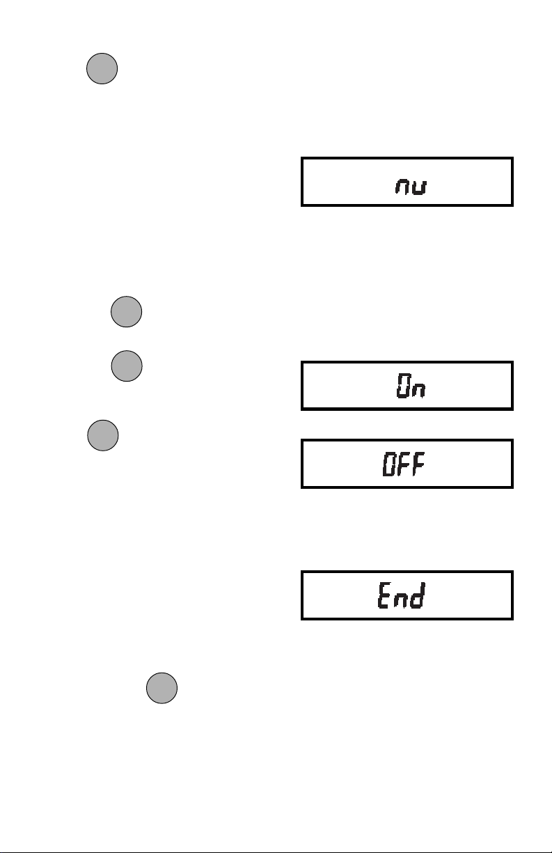
ONON
ON
When
ONON
is released, STABLE will be
TARETARE
TARE
TARETARE
displayed again and the Print menu will be
returned.
Print Numeric Data OnlyPrint Numeric Data Only
Print Numeric Data Only
Print Numeric Data OnlyPrint Numeric Data Only
This submenu is used to select numeric
data only, or full display data for RS232
output. Set this feature ON to output numeric display data only, or OFF to output
full display data as follows:
1. Access the Nu submenu to display
the current status.
OFFOFF
OFF
OFFOFF
Press
MODEMODE
to change the status.
MODE
MODEMODE
ONON
ON
ONON
TARETARE
TARE
TARETARE
to accept the displayed
2. Press
status.
ONON
ON
When
ONON
is released, NU will be dis-
TARETARE
TARE
TARETARE
played again and the Print menu will be
returned.
EndEnd
End
EndEnd
You must use END to exit the Print menu.
Changes you make in the Print menuChanges you make in the Print menu
Changes you make in the Print menu
Changes you make in the Print menuChanges you make in the Print menu
are only stored in memory if you useare only stored in memory if you use
are only stored in memory if you use
are only stored in memory if you useare only stored in memory if you use
End.End.
End.
End.End.
To exit the Print menu and store your
ONON
ON
selections, press
ONON
when END is dis-
TARETARE
TARE
TARETARE
played. The balance will be returned to
normal weighing operations.
12
Page 70
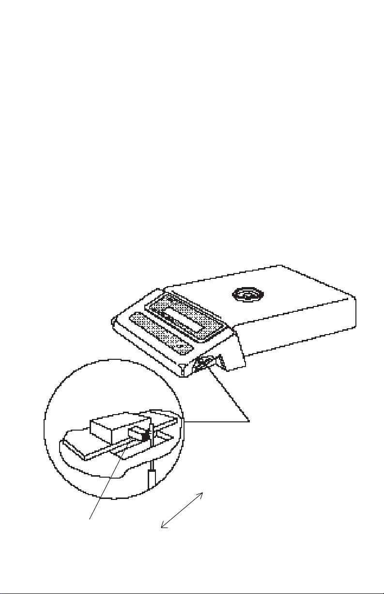
MENU LOCK-OUT PROTECTIONMENU LOCK-OUT PROTECTION
MENU LOCK-OUT PROTECTION
MENU LOCK-OUT PROTECTIONMENU LOCK-OUT PROTECTION
Access to the Print Menu can be disabled using the lock-out switch located under the
right side of the balance, near the display.
1. Turn display off and unplug the power cord.
2. Slide the balance toward you, with the front over the edge of a table. (You can also
turn the balance on its left side, but if you do, you MUST remove the draft shield,
pan and pan support first!)
3. Locate hole under display where
switch is located.
4. Using a small screwdriver, slide the
switch forward for LOCKED or back
for UNLOCKED.
5. Plug in the power cord and turn on the
balance.
LOCK-OUT SWITCH
UNLOCK
LOCK
13
Page 71
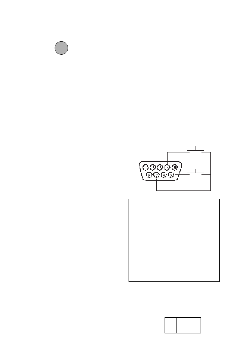
USING THE INTERFACEUSING THE INTERFACE
USING THE INTERFACE
USING THE INTERFACEUSING THE INTERFACE
When the interface is installed, a short
OFFOFF
OFF
press on the switch will initiate a
OFFOFF
MODEMODE
MODE
MODEMODE
print command. Data output is in the
format shown under the P command in the
RS232 Command Table.
When the interface is connected to a computer, two way communication between
the computer and balance is possible using the commands outlined in the RS232
Command Table.
HardwareHardware
Hardware
HardwareHardware
The balance can be interfaced with other
equipment utilizing the 9-pin subminiature “D” connector. The pinout and pin
connections are shown in the adjacent
illustration.
The balance will not output any data unless pin 5 (CTS) is held in an ON state (+3
to +15 VDC). Interfaces not utilizing the
CTS handshake may tie pin 5 to pin 6 to
defeat it.
RS232 CommandsRS232 Commands
RS232 Commands
RS232 CommandsRS232 Commands
All communication is accomplished using
standard ASCII format. Only the characters shown in the following table are acknowledged by the balance. Any other
commands, control characters or spaces
are ignored.
Commands sent to the balance must be
terminated with a carriage return (CR) or
carriage return-line line feed (CRLF). For
example, a tare command should appear
as shown in the adjacent diagram. Data
output by the balance is always terminated with a carriage return - line feed
(CRLF).
TARE *
PRINT *
1 5VDC (50 mA max.)
2 Data Out (TXD)
3 Data In (RXD)
4* Tare (External signal)
5 Clear To Send (CTS)
6 Data Terminal Ready (DTR)
7 Ground
8 Request To Send (RTS)
9* Print (External signal)
* External PRINT and/or TARE
switches may be installed as shown
in the diagram. Momentary contact switches must be used.
TARE COMMANDTARE COMMAND
TARE COMMAND
TARE COMMANDTARE COMMAND
Field: T CR LF
Length: 1 1 1
14
Page 72
RS232 COMMAND TABLERS232 COMMAND TABLE
RS232 COMMAND TABLE
RS232 COMMAND TABLERS232 COMMAND TABLE
CommandCommand
Command
CommandCommand
CharacterCharacter
Character
CharacterCharacter
??
? Print current mode
??
nnnAnnnA
nnnA Set Auto Print feature to “n”
nnnAnnnA
CC
C Begin span calibration
CC
xDxD
xD Set 1 second print delay (set x = 0 for OFF, or x = 1 for ON)
xDxD
xx
II
x
I Set Averaging Level to “x”,
xx
II
DescriptionDescription
Description
DescriptionDescription
(see table).
where x = 0 to 3 (see table).
Field: Mode Stab CR LF
Length: 5 1 1 1
Grams
Pennyweight
Carats
Avoidupois ounces
Troy ounces
Grains
Taels
n = 0 Turns feature OFF
n = S Output on stability
n = C Output is continuous
0 = minimum level
1=
2=
3 = maximum level
blank if stable
“ ? ” if unstable
Momme
Pounds
Pounds:ounces
Custom unit
Parts counting
Percent weighing
Error
LL
L Begin linearity calibration
LL
PP
P Print display data
PP
When “numeric only” display
data is selected for output in
the RS232 menu, the Mode
field is not output.
Field: Weight Mode Stab CR LF
Length: 9 1 5 1 1 1
Same as ? command
Displayed weight sent right justified w/lead
zero blanking.
Nine characters include:
decimal point (1)
weight (7 max))
polarity (1): blank if positive
“ - ” if negative
15
Page 73
RS232 COMMAND TABLE (Cont.)RS232 COMMAND TABLE (Cont.)
RS232 COMMAND TABLE (Cont.)
RS232 COMMAND TABLE (Cont.)RS232 COMMAND TABLE (Cont.)
CommandCommand
Command
CommandCommand
CharacterCharacter
Character
CharacterCharacter
xSxS
xS Set stable data only printing (set x = 0 for OFF, or x = 1 for ON).
xSxS
TT
T Same effect as pressing tare button
TT
VV
V Print EPROM version
VV
DescriptionDescription
Description
DescriptionDescription
Field: Model # EPROM # CR LF
Length: 7 15 1 1
Balance Model
xZxZ
xZ Set Auto Zero to “x”,
xZxZ
Esc LEsc L
Esc L Prints listing of Setup and Print menu settings.
Esc LEsc L
Esc REsc R
Esc R Resets Setup and Print menus to factory defaults.
Esc REsc R
Esc SEsc S
Esc S Save current settings.
Esc SEsc S
where x = 0 to 3 (see table).
CAUTION: This will reset RS232 configuration.
"98101-XX Sr*XX.X"
0 = OFF
1 = .5 d
2=1 d
3=3 d
16
Page 74

CARE AND MAINTENANCECARE AND MAINTENANCE
CARE AND MAINTENANCE
CARE AND MAINTENANCECARE AND MAINTENANCE
The RS232 Interface Accessory once installed does not require maintenance.
TROUBLESHOOTINGTROUBLESHOOTING
TROUBLESHOOTING
TROUBLESHOOTINGTROUBLESHOOTING
SYMPTOM
RS232 interface not
working.
Error CodesError Codes
Error Codes
Error CodesError Codes
When the RS232 interface is installed in Precision Standard and Analytical Standard
balances, the following error codes are added to the standard list of error codes:
4.0 Bad RS232 frame. Check RS232 menu parameters and correct.
4.4 RS232 buffer is full. May occur if no printer or computer is connected to the
interface. To clear buffer turn balance off, or enter and exit Print menu and select
END.
4.5 Function is disabled by the Lockswitch.
SERVICE INFORMATIONSERVICE INFORMATION
SERVICE INFORMATION
SERVICE INFORMATIONSERVICE INFORMATION
PROBABLE CAUSE(S)
Print menu settings not
properly set up.
Cable connections.
Verify interface settings in
Print menu correspond to
those of peripheral device.
Check cable connections.
REMEDY
If the Troubleshooting section does not resolve or describe your problem, you will need
to contact an authorized Ohaus Service Agent. For Service assistance in the United
States, please call Ohaus Corporation toll-free at (800) 526-0659. An Ohaus Product
Service Specialist will be available to help you.
17
Page 75

18
Page 76

LIMITED WARRANTYLIMITED WARRANTY
LIMITED WARRANTY
LIMITED WARRANTYLIMITED WARRANTY
Ohaus products are warranted against defects in materials and
workmanship from the date of delivery through the duration of the
warranty period. During the warranty period Ohaus will repair, or, at its
option, replace any component(s) that proves to be defective at no
charge, provided that the product is returned, freight prepaid, to
Ohaus.
This warranty does not apply if the product has been damaged by
accident or misuse, exposed to radioactive or corrosive materials, has
foreign material penetrating to the inside of the product, or as a result
of service or modification by other than Ohaus. In lieu of a properly
returned warranty registration card, the warranty period shall begin on
the date of shipment to the authorized dealer. No other express or
implied warranty is given by Ohaus Corporation. Ohaus Corporation
shall not be liable for any consequential damages.
As warranty legislation differs from state to state and country to
country, please contact Ohaus or your local Ohaus dealer for further
details.
19
Page 77

Ohaus Corporation Ohaus Europe Ltd.
29 Hanover Road, ENGLAND
Florham Park, NJ 07932, USA Tel: +44 (0) 1954 251343,
Tel: (201) 377-9000, Fax: +44 (0) 1954 250205
Fax: (201) 593-0359
With offices in Germany, France, Spain, Italy, Canada, Mexico and Japan.
P/N 77017-01 R0296 © Ohaus Corporation 1993, 1996 all rights reserved.
20
 Loading...