

Page 1
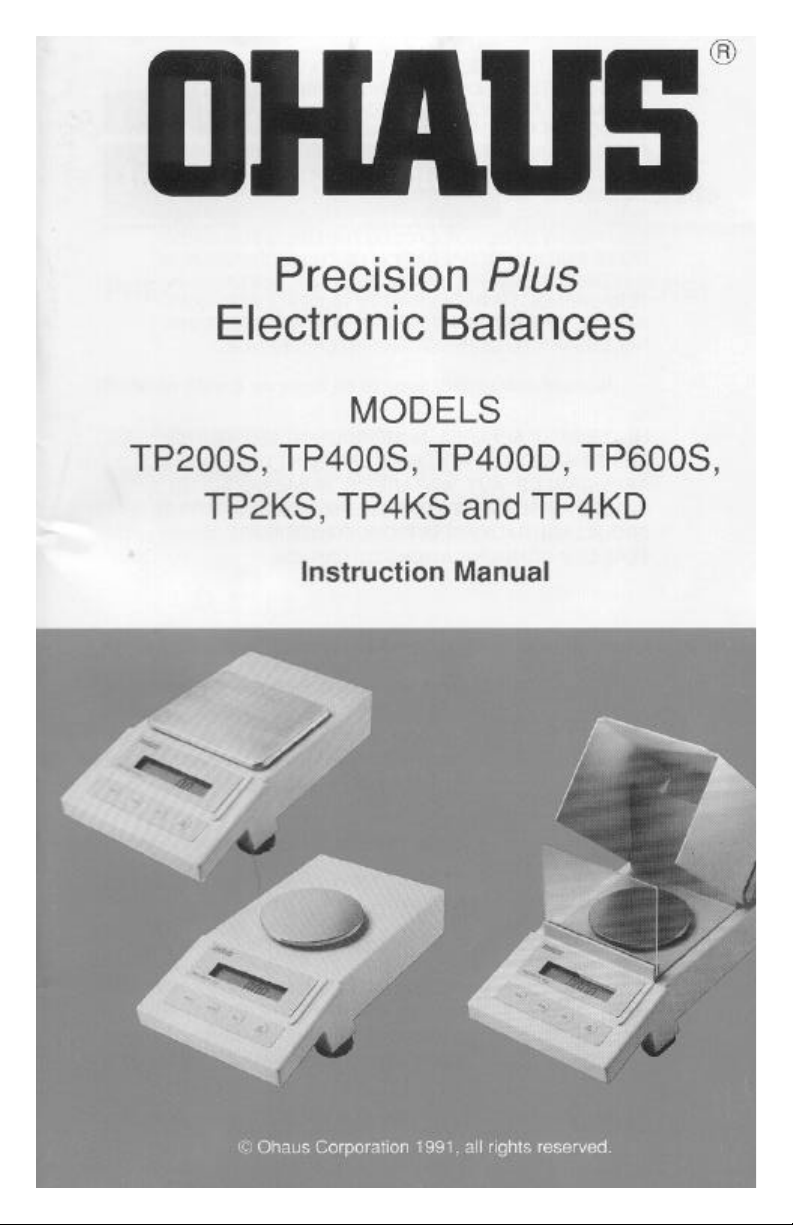
Page 2
Page 3
Page 4
Page 5
Page 6
Page 7
Page 8
Page 9
Page 10
Page 11
Page 12
Page 13
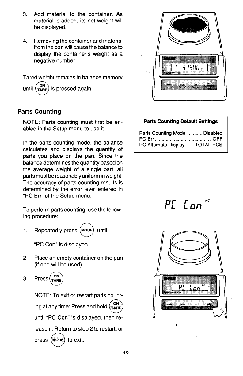
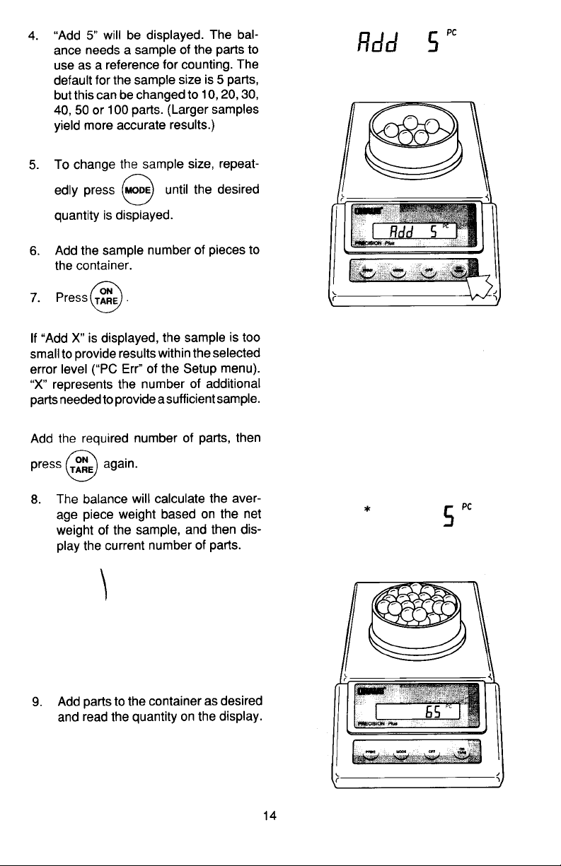
Page 14
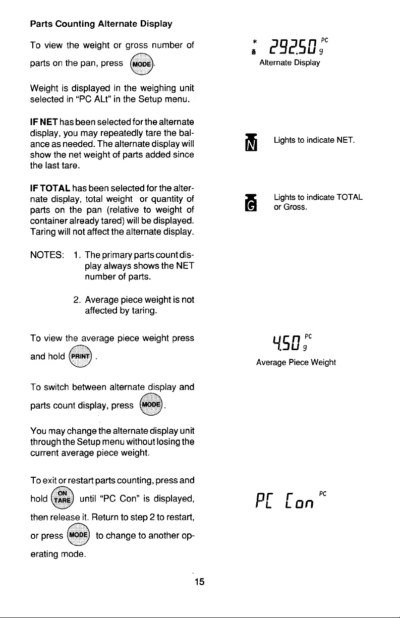
Page 15
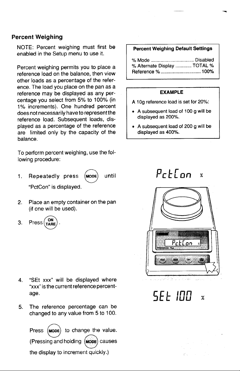
Page 16
Page 17
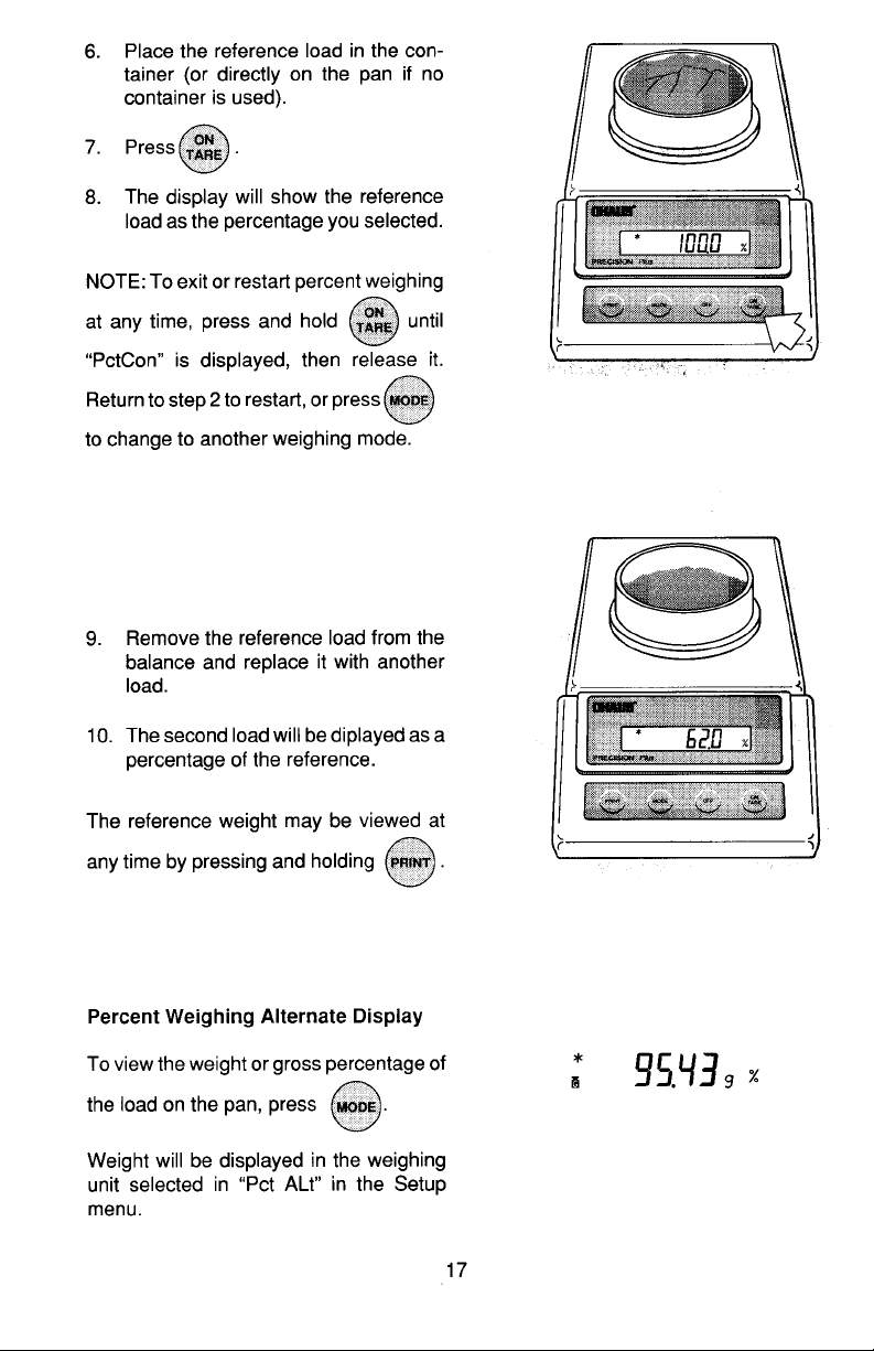
Page 18
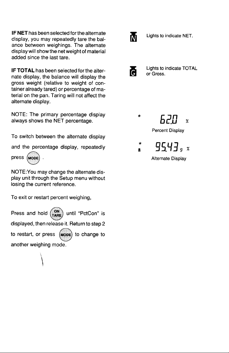
Page 19
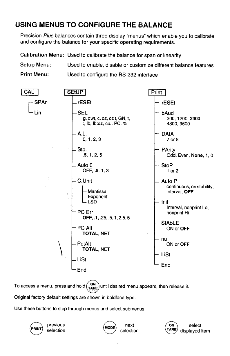
Page 20
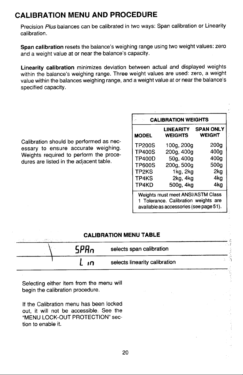
Page 21
Page 22
Page 23
Page 24
Page 25
Page 26
Page 27
Page 28
Page 29
Page 30
Page 31
Page 32
Page 33
Page 34
Page 35
Page 36
Page 37
Page 38
Page 39
Page 40
Page 41
Page 42
Page 43
Page 44
Page 45
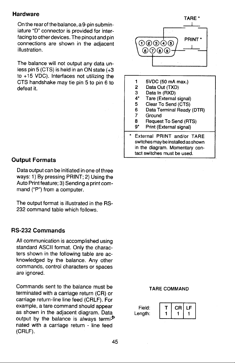
Page 46
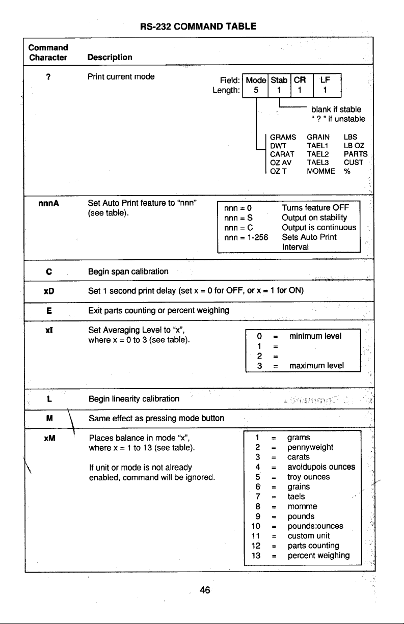
Page 47
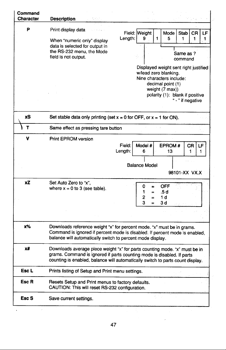
Page 48
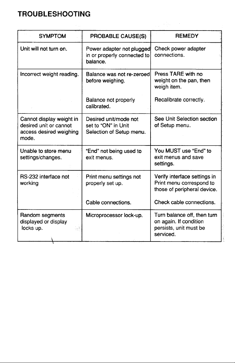
Page 49

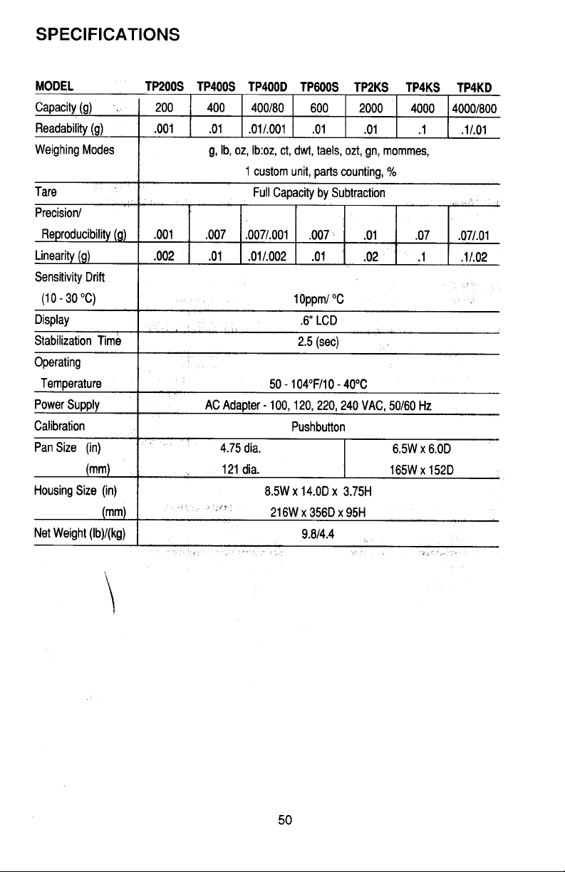
Page 50
Page 51
Page 52

Page 53
Page 54

Ohaus Corporation
29 Hanover Road
Florham Park NJ
07932-0900
PRECISION
Electronic Balances
Models TP200, TP400, TP400D,
TP600, TP2K, TP4K and TP4KD
Plus
Instruction Manual
Page 55

NOTICE:NOTICE:
NOTICE: THIS EQUIPMENT HAS BEEN TESTED AND FOUND TO
NOTICE:NOTICE:
COMPLY WITH THE LIMITS FOR A CLASS A DIGITAL DEVICE, PURSUANT TO PART 15 OF THE FCC RULES.
THESE LIMITS ARE DESIGNED TO PROVIDE REASONABLE PROTECTION AGAINST HARMFUL INTERFERENCE WHEN THE
EQUIPMENT IS OPERATED IN A COMMERCIAL ENVIRONMENT.
THIS EQUIPMENT GENERATES, USES, AND CAN RADIATE RADIO
FREQUENCY ENERGY AND, IF NOT INSTALLED AND USED IN ACCORDANCE WITH THE INSTRUCTION MANUAL, MAY CAUSE
HARMFUL INTERFERENCE TO RADIO COMMUNICATIONS. OPERATION OF THIS EQUIPMENT IN A RESIDENTIAL AREA IS LIKELY
TO CAUSE HARMFUL INTERFERENCE IN WHICH CASE THE USER
WILL BE REQUIRED TO CORRECT THE INTERFERENCE AT HIS
OWN EXPENSE.
THIS DIGITAL APPARATUS DOES NOT EXCEED THE CLASS A LIMITS FOR RADIO NOISE EMISSIONS FROM DIGITAL APPARATUS AS
SET OUT IN THE INTERFERENCE-CAUSING EQUIPMENT STANDARD ENTITLED “DIGITAL APPARATUS”, ICES-003 OF THE
DEPARTMENT OF COMMUNICATIONS.
CET APPAREIL NUMERIQUE RESPECTE LES LIMITES DE BRUITS
RADIOELECTRIQUES APPLICABLES AUX APPAREILS NUMERIQUES
DE CLASSE A PRESCRITES DANS LA NORME SUR LE MATERIEL
BROUILLEUR : “APPAREILS NUMERIQUES”, NMB-003 EDICTEE PAR
LE MINISTRE DES COMMUNICATIONS.
Unauthorized changes or modifications to this equipment are not
permitted.
2
Page 56

TABLE OF CONTENTSTABLE OF CONTENTS
TABLE OF CONTENTS
TABLE OF CONTENTSTABLE OF CONTENTS
INTRODUCTION ....................................................................................................................................... 5
DESCRIPTION ..........................................................................................................................................5
UNPACKING .............................................................................................................................................6
INSTALLATION ......................................................................................................................................... 7
Environment .....................................................................................................................................7
In-Service Cover...............................................................................................................................7
Leveling the Balance ........................................................................................................................ 7
Draft Shield (TP200 and TP400D) .................................................................................................... 8
Pan and Pan Support ....................................................................................................................... 8
Square Pan.................................................................................................................................. 8
Round Pan................................................................................................................................... 9
Weigh Below Hook ...........................................................................................................................9
AC Adapter....................................................................................................................................... 9
OPERATION ...........................................................................................................................................10
Turning the Balance On.................................................................................................................. 10
Stabilization .................................................................................................................................... 10
Auto Range Models (TP400D and TP4KD) .................................................................................... 11
Checking Calibration ...................................................................................................................... 11
Selecting a Weighing Unit .............................................................................................................. 11
Weighing ........................................................................................................................................12
Taring .............................................................................................................................................12
Parts Counting................................................................................................................................ 13
Percent Weighing ...........................................................................................................................15
USING MENUS TO CONFIGURE THE BALANCE ................................................................................. 18
CALIBRATION MENU .............................................................................................................................19
Calibration Menu Protection ...........................................................................................................19
Calibration Weights ........................................................................................................................19
Span Calibration .............................................................................................................................20
Linearity Calibration ........................................................................................................................ 21
End................................................................................................................................................. 22
USER MENU ...........................................................................................................................................23
User Menu Protection..................................................................................................................... 23
Reset to Factory Defaults ............................................................................................................... 24
Averaging Level.............................................................................................................................. 25
Stability Range ............................................................................................................................... 26
Auto-Zero .......................................................................................................................................26
End................................................................................................................................................. 27
3
Page 57

SETUP MENU .........................................................................................................................................28
Setup Menu Protection ...................................................................................................................28
Reset to Factory Defaults ............................................................................................................... 29
Unit Selection ................................................................................................................................. 30
Taels ..............................................................................................................................................30
Custom Unit Conversion Factor...................................................................................................... 31
Parts Counting Error Level ............................................................................................................. 33
Parts Counting Alternate Display.................................................................................................... 34
Percent Weighing Alternate Display ............................................................................................... 36
Lockswitch......................................................................................................................................37
List..................................................................................................................................................38
End................................................................................................................................................. 38
PRINT MENU .......................................................................................................................................... 39
Print Menu Protection .....................................................................................................................39
Reset to Factory Defaults ............................................................................................................... 40
Baud Rate ......................................................................................................................................41
Data Bits......................................................................................................................................... 41
Parity ..............................................................................................................................................42
Stop Bits .........................................................................................................................................42
Auto Print Feature ..........................................................................................................................43
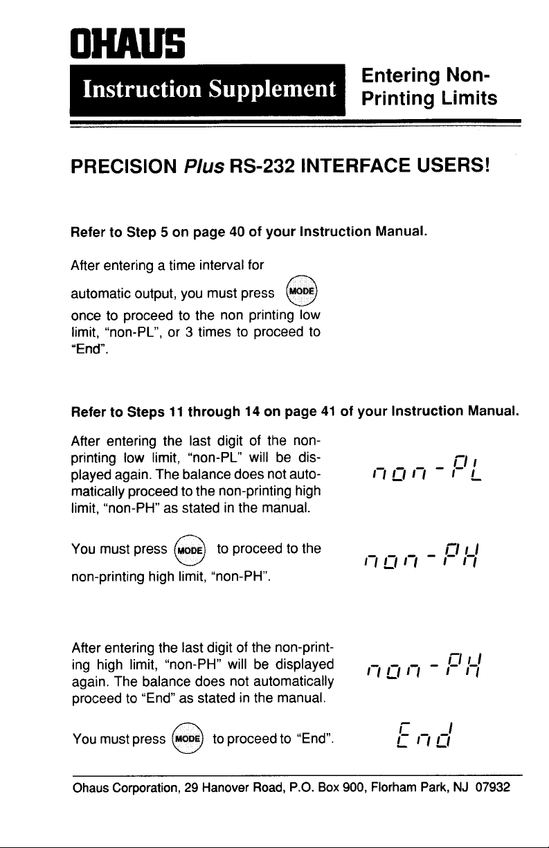
Auto Print Time Interval and Non Printing Weight Values............................................................... 43
Print Stable Data Only ....................................................................................................................45
Print Numeric Data Only ................................................................................................................. 46
List..................................................................................................................................................46
End................................................................................................................................................. 46
MENU LOCK-OUT PROTECTION .......................................................................................................... 47
RS232 INTERFACE ................................................................................................................................ 48
Hardware........................................................................................................................................48
Output Formats...............................................................................................................................48
RS232 Commands ......................................................................................................................... 49
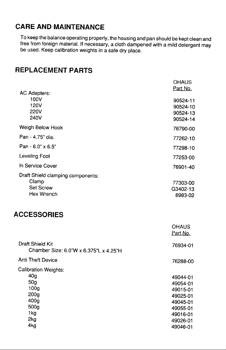
CARE AND MAINTENANCE ................................................................................................................... 52
TROUBLESHOOTING ............................................................................................................................52
Error Codes ....................................................................................................................................53
SERVICE INFORMATION....................................................................................................................... 54
SPECIFICATIONS...................................................................................................................................55
PARTS INFORMATION .......................................................................................................................... 56
REPLACEMENT PARTS.........................................................................................................................56
ACCESSORIES ......................................................................................................................................56
LIMITED WARRANTY ............................................................................................................... ..............57
4
Page 58
INTRODUCTION
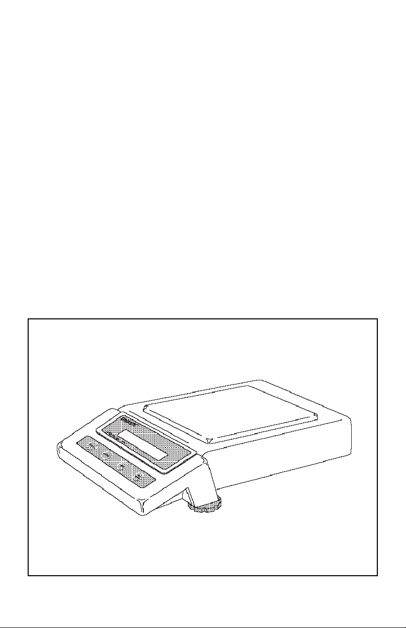
This manual covers installation, operation and troubleshooting for the Ohaus Precision Plus balances, Models TP200, TP400, TP400D, TP600, TP2K, TP4K and
TP4KD. To insure proper operation of the balance, please read this manual
completely.
DESCRIPTIONDESCRIPTION
DESCRIPTION
DESCRIPTIONDESCRIPTION
The Ohaus Precision Plus series balances are precision weighing instruments,
designed to provide years of service with virtually no maintenance. The Precision Plus
series is constructed using a die-cast aluminum base finished with a durable epoxy
powder paint which is resistant to commonly used acids, contains a one piece solidstate precision electronics PC board, a seven digit LCD display which is 0.6 inches in
height. All Precision Plus series balances are factory set to measure in grams. Each
balance operates through a series of menus which enable precise calibration and
linearity along with various other parameters which enhances operation. A built in lock
switch prevents preset settings from being changed. To prevent measurements from
being affected by air currents, a Draft Shield is mounted to the balance and is available
for ModelsTP200 and TP400D. Power is supplied through an AC adapter which is
available in five voltages for world-wide usage. Accessories include: an RS232
interface kit which allows printing of results through an external computer, an RS232
Interface cable with a print switch, weigh below hook, security device and calibration
weights.
PRECISION
Plus
5
Balance
Page 59
UNPACKINGUNPACKING
UNPACKING
UNPACKINGUNPACKING
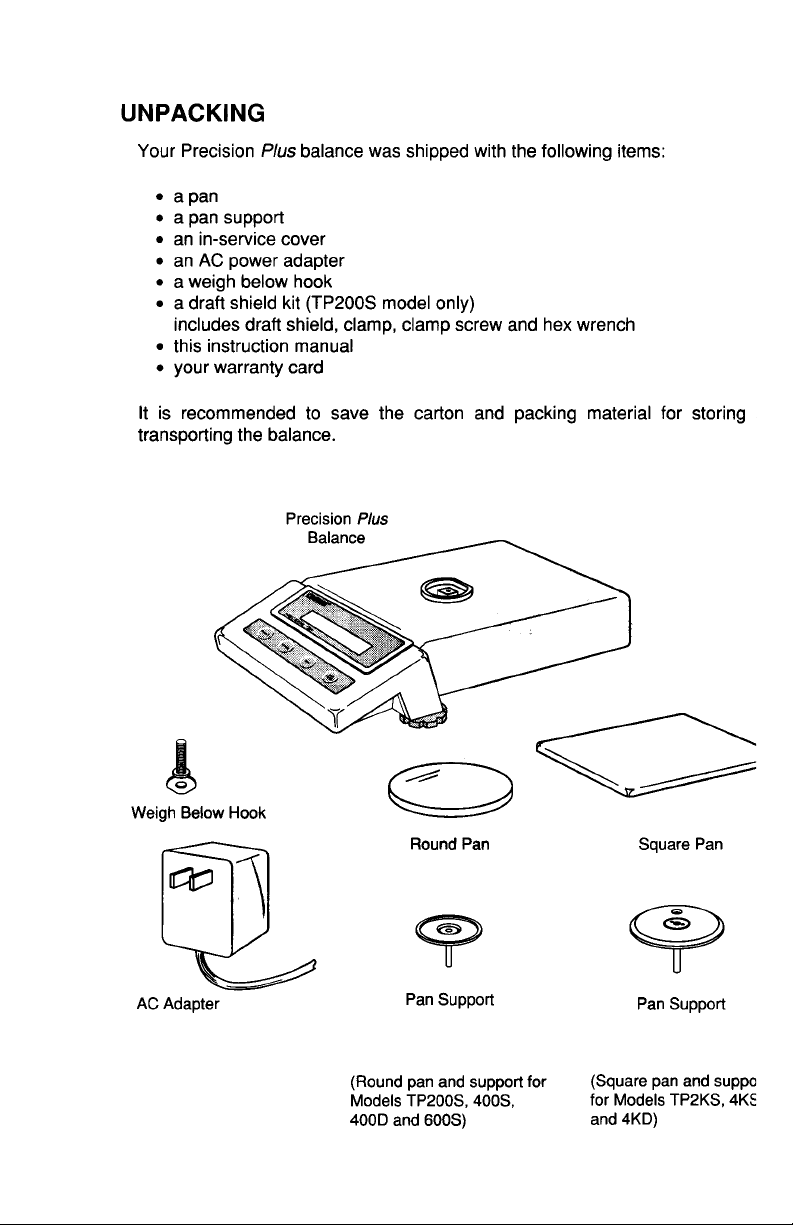
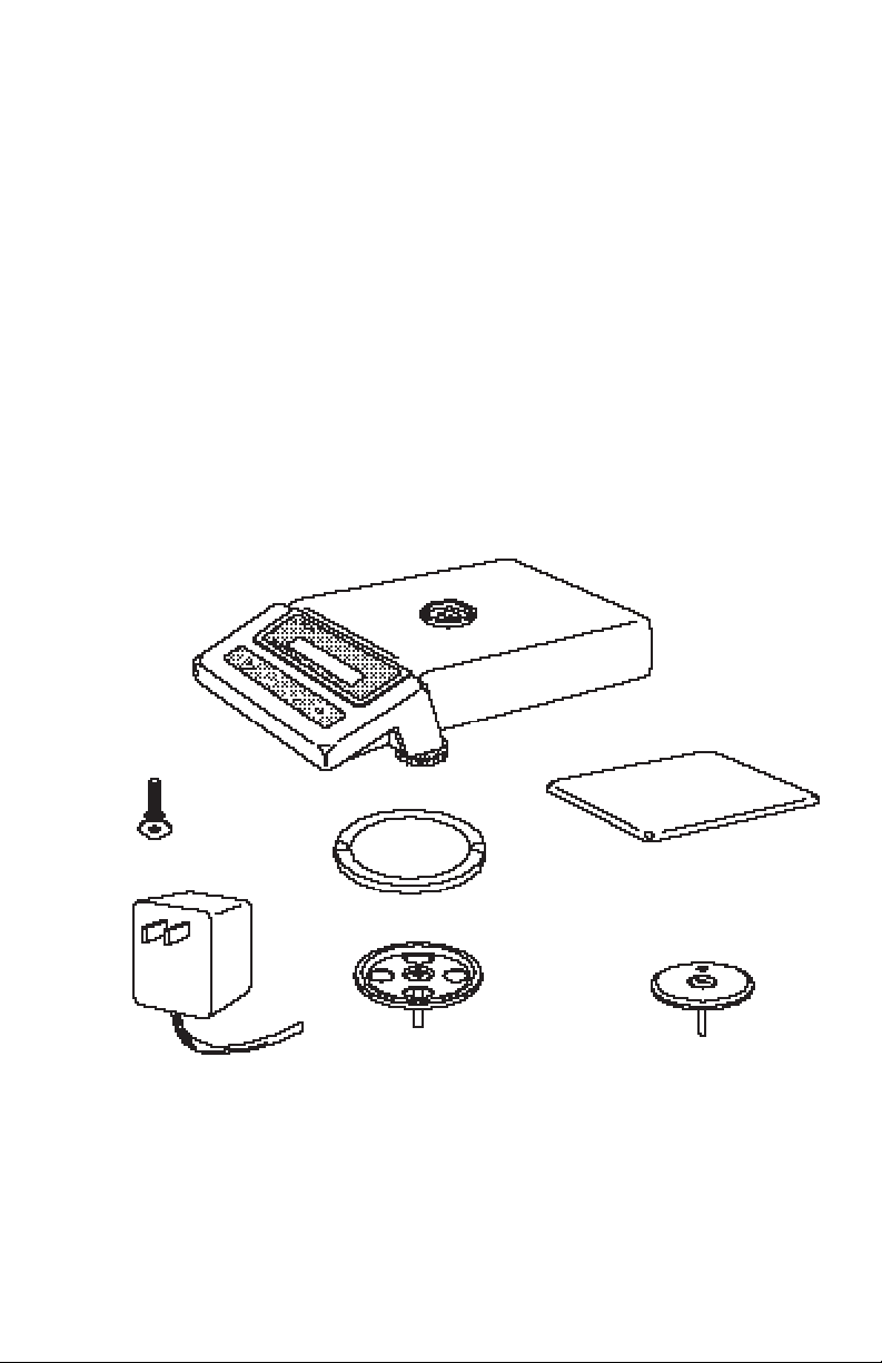
Your Precision Plus balance was shipped with the following items:
• a pan
• a pan support
• an in-service cover
• an AC power adapter
• a weigh below hook
• a draft shield (TP200 and TP400D only)
includes draft shield and snap clamp
• this instruction manual
• your warranty card
It is recommended to save the carton and packing material for storing, transporting the
balance or returning it for service.
Precision Plus
Balance
Weigh Below Hook
Round Pan
Pan Support Pan SupportAC Adapter
(Round pan and support for
Models TP200, TP400,
TP400D and TP600)
6
6
Square Pan
(Square pan and support
for Models TP2K, TP4K
and TP4KD)
Page 60
INSTALLATIONINSTALLATION
INSTALLATION
INSTALLATIONINSTALLATION
EnvironmentEnvironment
Environment
EnvironmentEnvironment
The balance should always be used in an environment which is free from excessive
air currents, corrosives, vibration, and temperature or humidity extremes. These
factors will affect displayed weight readings.
DO NOT install the balance:
• Next to open windows or doors causing drafts or rapid temperature changes.
• Near air conditioning or heat vents.
• Near vibrating, rotating or reciprocating equipment.
• Near magnetic fields or equipment that generates magnetic fields.
• On an unlevel work surface.
In-Service CoverIn-Service Cover
In-Service Cover
In-Service CoverIn-Service Cover
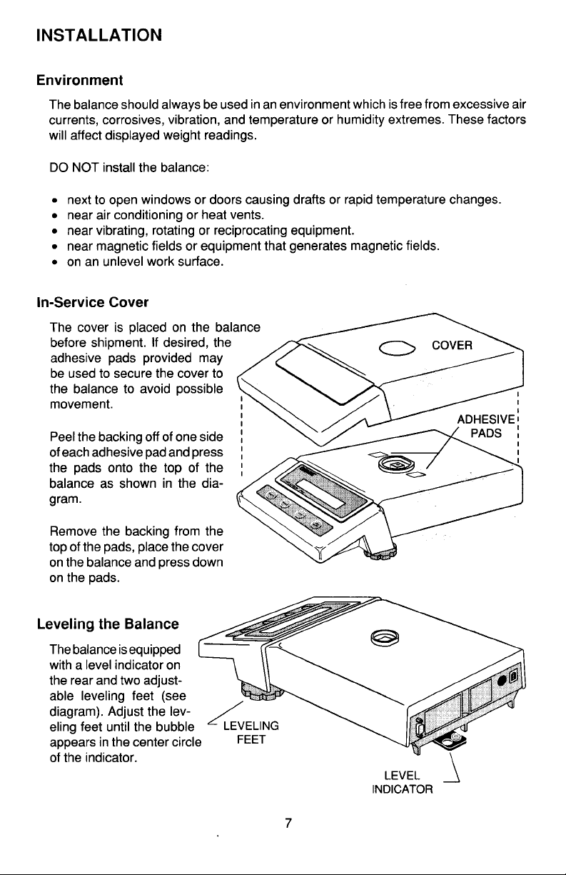
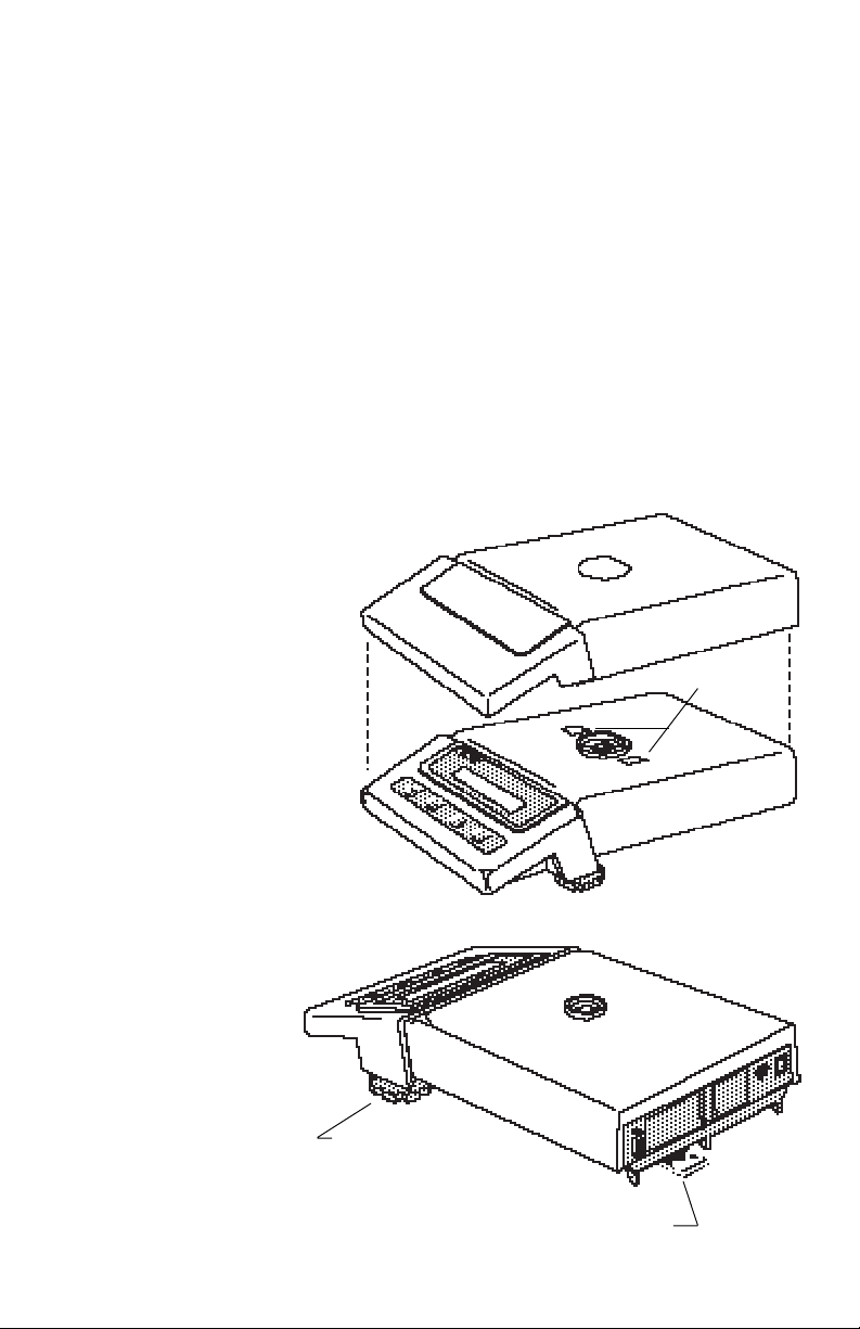
The cover is placed on the balance
before shipment. If desired, the
adhesive pads provided may
be used to secure the cover to
the balance to avoid possible
movement.
Peel the backing off of one side
of each adhesive pad and press
the pads onto the top of the
balance as shown in the diagram.
COVER
ADHESIVE
PADS
Remove the backing from the
top of the pads, place the cover
on the balance and press down
on the pads.
Leveling the BalanceLeveling the Balance
Leveling the Balance
Leveling the BalanceLeveling the Balance
The balance is
equipped with a level
indicator on the rear and
two adjustable leveling
feet (see diagram). Adjust the leveling feet until
the bubble appears in the
center circle of the indicator.
LEVELING
FEET (2)
LEVEL
INDICATOR
7
Page 61
Draft Shield (TP200 and TP400D )Draft Shield (TP200 and TP400D )
Draft Shield (TP200 and TP400D )
Draft Shield (TP200 and TP400D )Draft Shield (TP200 and TP400D )
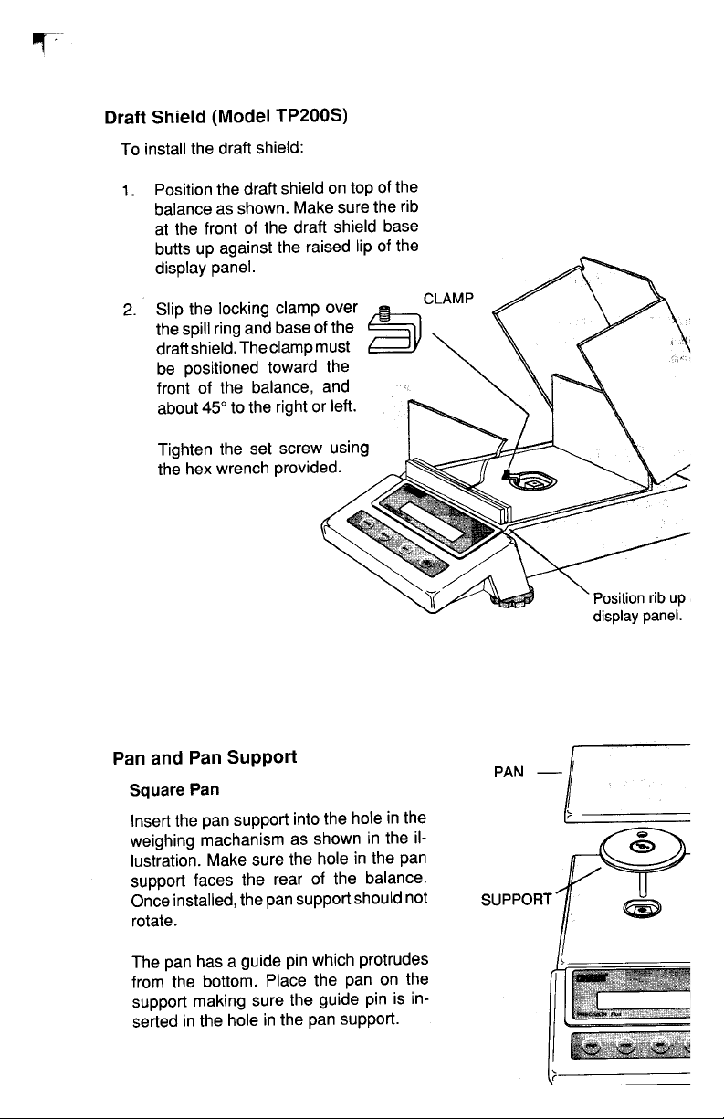
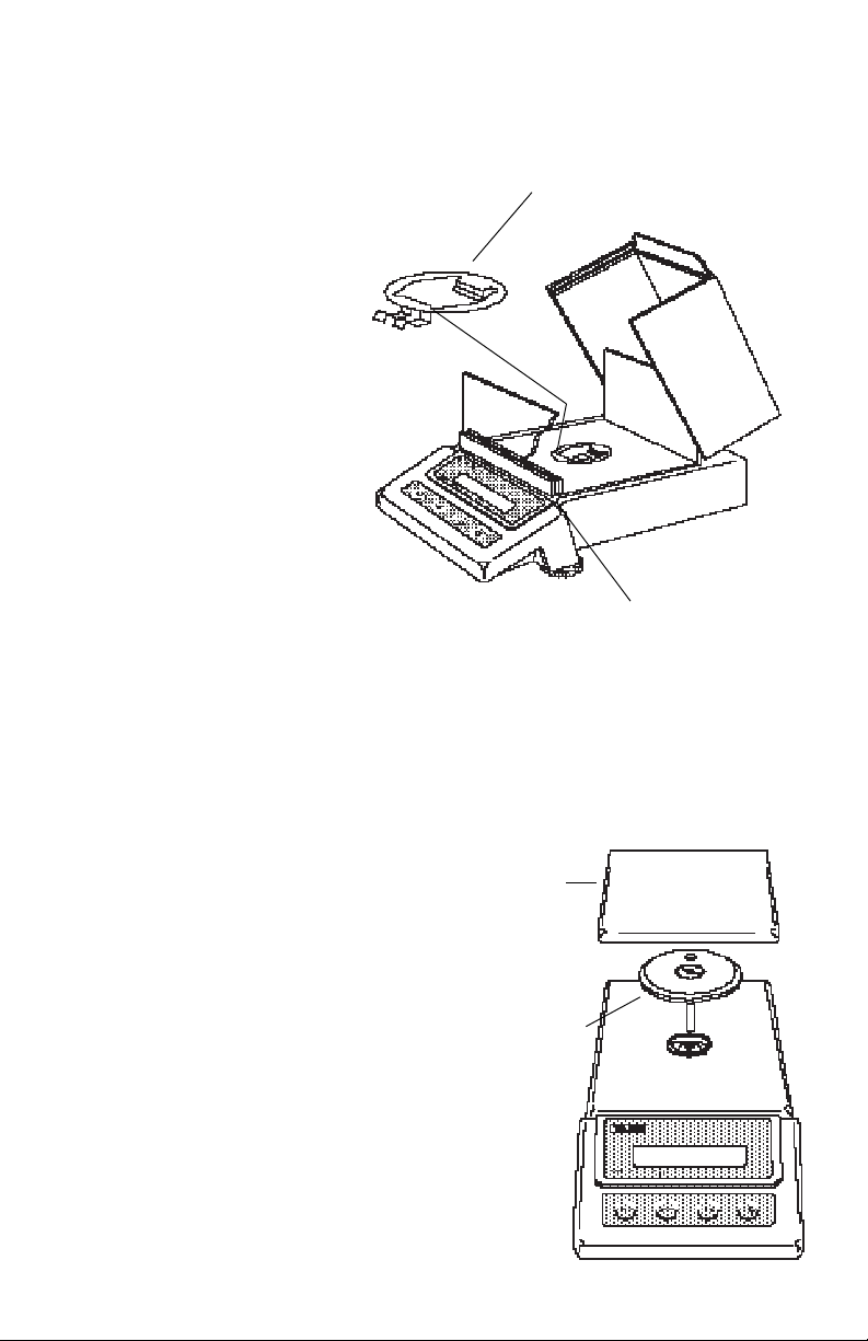
To install the draft shield:
1. Position the draft shield on top of the
balance as shown. Make sure the rib
at the front of the draft shield base
butts up against the raised lip of the
display panel.
2. The snap clamp should be
oriented so that the double
clip is toward the front of the
balance.
Insert the double clip of the
snap clamp into the opening in the draft shield base,
and clip the draft shield
base to the balance. Press
the rear clip of the snap
clamp into place.
Snap
Clamp
Position rib up
against display panel.
Pan and Pan SupportPan and Pan Support
Pan and Pan Support
Pan and Pan SupportPan and Pan Support
Square PanSquare Pan
Square Pan
Square PanSquare Pan
Insert the pan support into the hole in the
weighing mechanism as shown in the
illustration. Make sure the hole in the pan
support faces the rear of the balance.
Once installed, the pan support should
not rotate.
The pan has a guide pin which protrudes
from the bottom. Place the pan on the
support making sure the guide pin is inserted in the hole in the pan support.
8
8
PAN
SUPPORT
Page 62
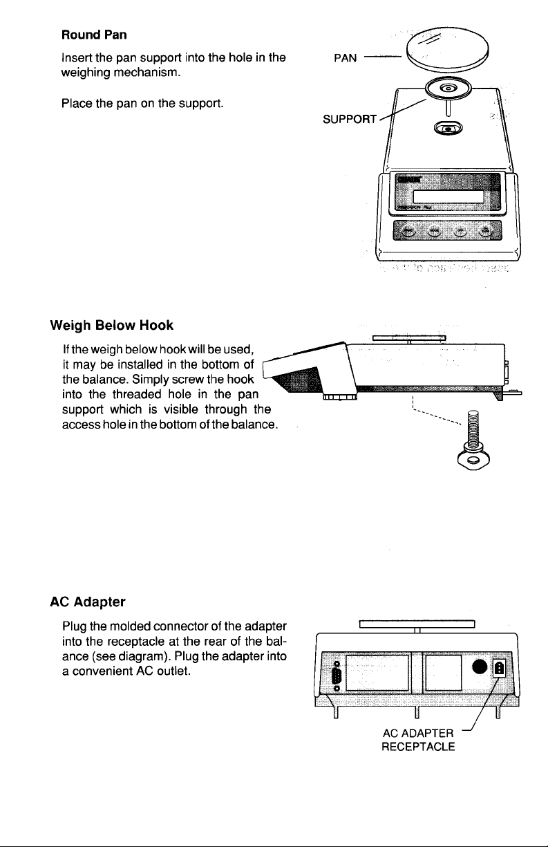
Round PanRound Pan
Round Pan
Round PanRound Pan
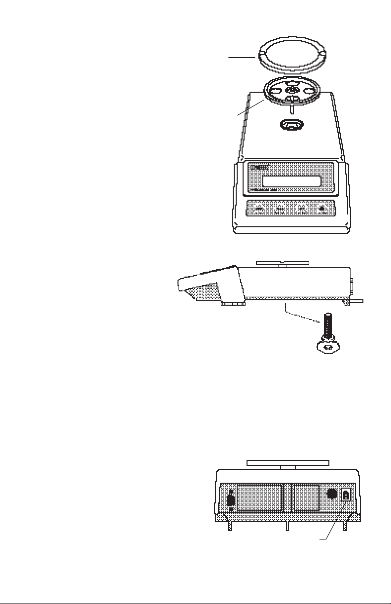
Insert the pan support into the hole in the
weighing mechanism.
Place the pan on the support.
Weigh Below HookWeigh Below Hook
Weigh Below Hook
Weigh Below HookWeigh Below Hook
If the weigh below hook will be used, it
may be installed in the bottom of the
balance. Simply screw the hook into
the threaded hole in the pan support
which is visible through the access
hole in the bottom of the balance.
PAN
SUPPORT
AC AdapterAC Adapter
AC Adapter
AC AdapterAC Adapter
Plug the molded connector of the adapter
into the receptacle at the rear of the balance (see diagram). Plug the adapter into
a convenient AC outlet. When power is
applied to the balance, it will begin a self
test cycle. During this time, the display will
count down from 10 and display the word
CHEC.
AC ADAPTER
RECEPTACLE
9
Page 63
OPERATIONOPERATION
OPERATION
OPERATIONOPERATION
Turning the Balance ONTurning the Balance ON
Turning the Balance ON
Turning the Balance ONTurning the Balance ON
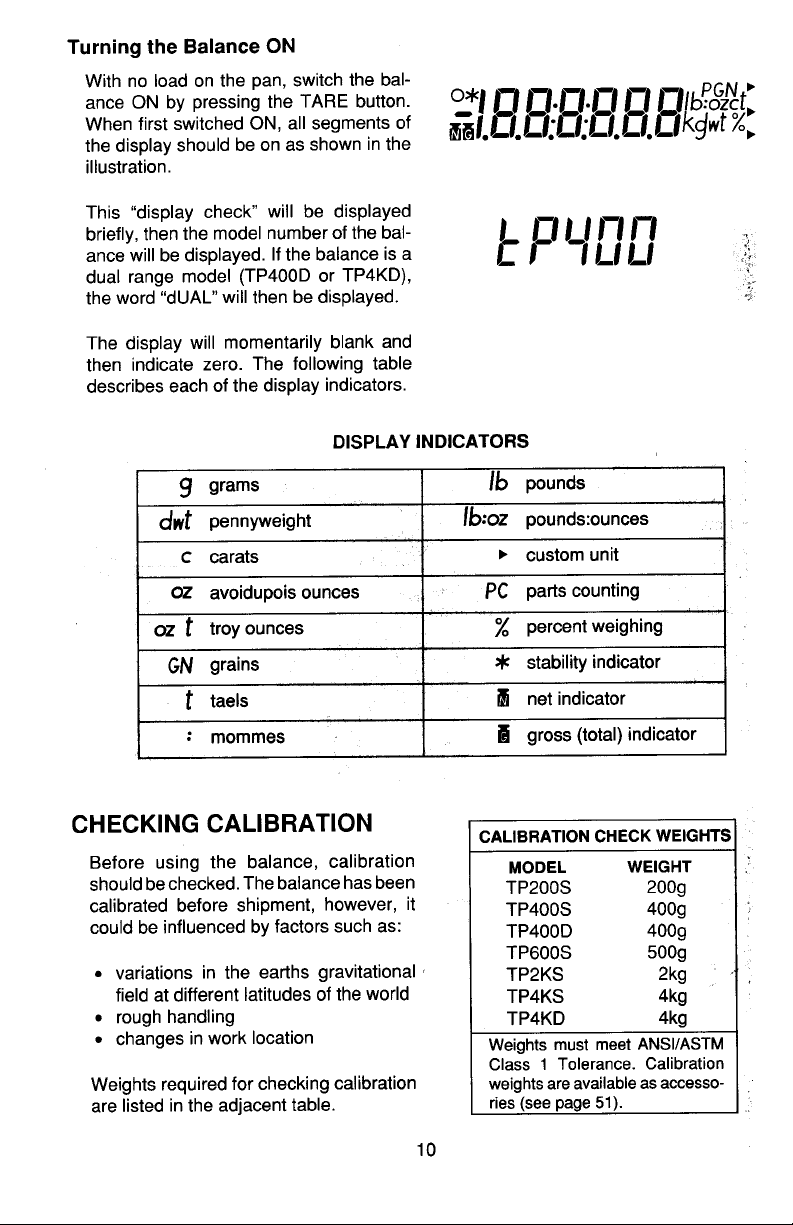
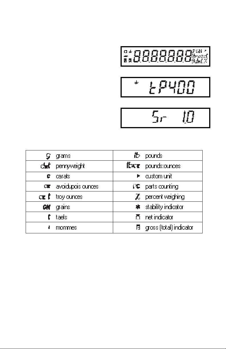
With no load on the pan, switch the balance ON by pressing the ON TARE button. When first switched ON, all segments
of the display should be on as shown in
the illustration.
This display check will be displayed briefly,
then the model number of the balance
followed by a software revision number.
The display will momentarily blank and
then indicate zero. The following table
describes each of the display indicators.
DISPLAY INDICATORSDISPLAY INDICATORS
DISPLAY INDICATORS
DISPLAY INDICATORSDISPLAY INDICATORS
StabilizationStabilization
Stabilization
StabilizationStabilization
Before initally using the balance, allow
time for it to adjust to changes in environment. The balance need only be plugged
in to warm up. Recommended warm up
period is thirty minutes.
10
Page 64
5. To lock out the other menus, press
and repeat the procedure in
MODEMODE
MODE
MODEMODE
steps 3 and 4.
ListList
List
ListList
This submenu can be used to output a
listing of current menu settings via the
RS232 interface. When selected, menu
settings for the User, Setup and Print
menus will be output. To use this feature,
your balance must be connected to a
computer or printer.
To obtain a listing of current settings,
ONON
ON
ONON
simply press
when LIST is dis-
TARETARE
TARE
TARETARE
played in the Setup menu.
EndEnd
End
EndEnd
You must use End to exit the Setup menu.
Changes you make in the Setup menuChanges you make in the Setup menu
Changes you make in the Setup menu
Changes you make in the Setup menuChanges you make in the Setup menu
are only stored in memory if you useare only stored in memory if you use
are only stored in memory if you use
are only stored in memory if you useare only stored in memory if you use
End.End.
End.
End.End.
To exit the Setup menu and store your
ONON
ON
ONON
settings, press
when END is dis-
TARETARE
TARE
TARETARE
played.
ONON
ON
When
ONON
is released, the balance will
TARETARE
TARE
TARETARE
be returned to normal weighing operations.
11
Page 65
WeighingWeighing
Weighing
WeighingWeighing
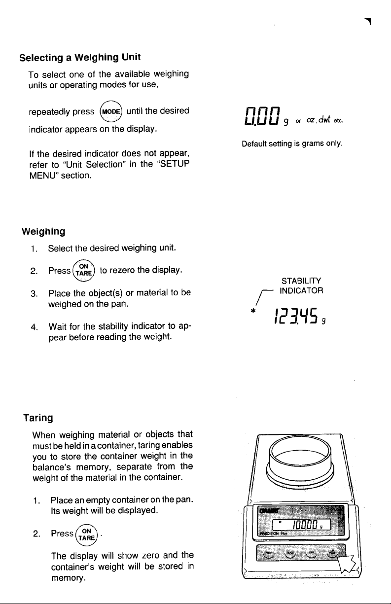
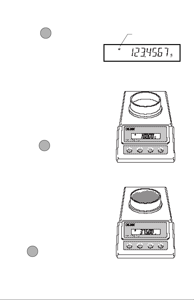
ONON
ON
1. Press to rezero the display.
ONON
TARETARE
TARE
TARETARE
2. Place the object(s) or material to be
weighed on the pan.
3. Wait for the stability indicator to appear before reading the weight.
TaringTaring
Taring
TaringTaring
When weighing material or objects that
must be held in a container, taring enables you to store the container weight in
the balance’s memory, separate from the
weight of the material in the container.
1. Place an empty container on the pan.
Its weight will be displayed.
ONON
ON
2. Press
ONON
TARETARE
TARE
TARETARE
.
The display will show zero and the
container’s weight will be stored in
memory.
STABILITY
INDICATOR
3. Add material to the container. As
material is added, its net weight will
be displayed.
4. Removing the container and material
from the pan will cause the balance to
display the container’s weight as a
negative number.
Tared weight remains in balance memory
ONON
ON
ONON
until
is pressed again.
TARETARE
TARE
TARETARE
12
Page 66
Parts CountingParts Counting
Parts Counting
Parts CountingParts Counting
NOTE:NOTE:
NOTE: Parts counting must first be en-
NOTE:NOTE:
abled in the Setup menu to use it.
In the parts counting mode, the balance
calculates and displays the quantity of
parts you place on the pan. Since the
balance determines the quantity based
on the average weight of a single part, all
parts must be reasonably uniform in
weight. The accuracy of parts counting
results is determined by the error level
entered in PC Err of the Setup menu.
To perform parts counting, use the following procedure:
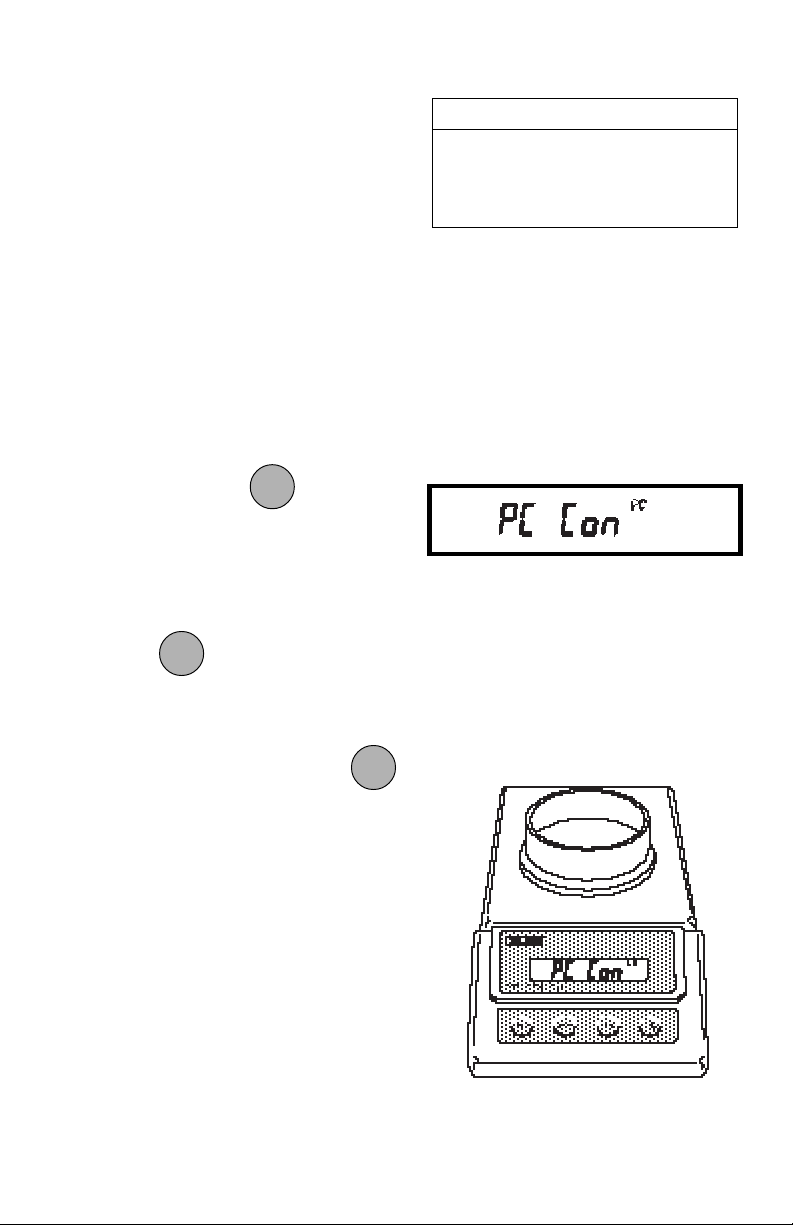
MODEMODE
MODE
1. Repeatedly press
MODEMODE
until PC Con
is displayed.
2. Place an empty container on the pan
(if one will be used).
ONON
ON
3. Press
ONON
TARETARE
TARE
TARETARE
.
Parts Counting Default SettingsParts Counting Default Settings
Parts Counting Default Settings
Parts Counting Default SettingsParts Counting Default Settings
Parts Counting Mode........... Disabled
PC Err ......................................... OFF
PC Alternate Display ..... TOTAL PCS
NOTE: NOTE:
NOTE: To exit or restart parts count-
NOTE: NOTE:
ONON
ON
ing at any time: Press and hold
ONON
TARETARE
TARE
TARETARE
until PC Con is displayed, then release it. Return to step 2 to restart, or
press to exit.
4. Add 5 will be displayed. The balance
needs a sample of the parts to use as
a reference for counting. The default
for the sample size is 5 parts, but this
can be changed to 10, 20, 30, 40, 50
or 100 parts. (Larger samples yield
more accurate results.)
13
Page 67
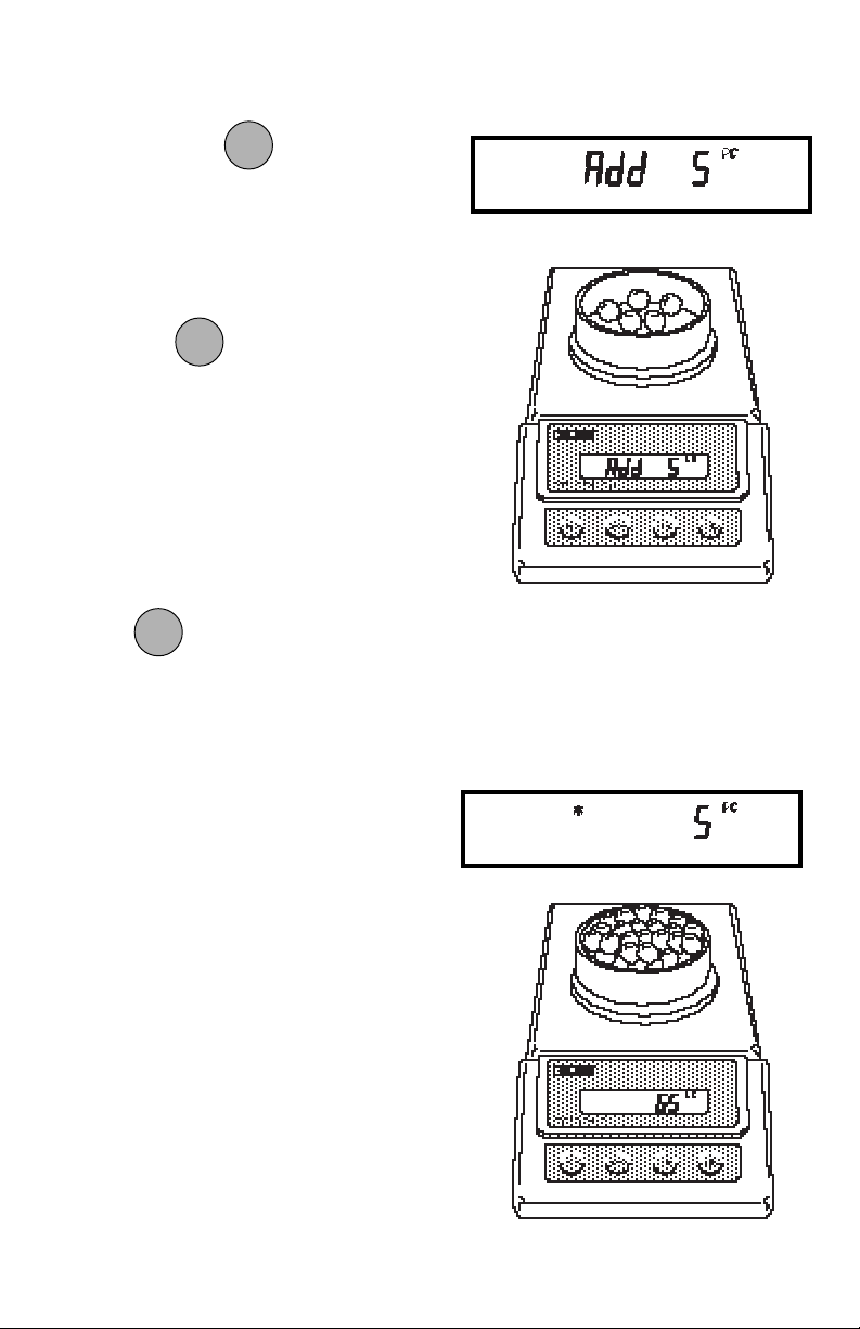
5. To change the sample size, repeat-
MODEMODE
MODE
edly press until the desired
MODEMODE
quantity is displayed.
6. Add the sample number of pieces to
the container.
ONON
ON
7. Press
ONON
TARETARE
TARE
TARETARE
.
If Add X is displayed, the sample is too
small to provide results within the selected error level (PC Err of the Setup
menu). X represents the number of additional parts needed to provide a sufficient
sample.
Add the required number of parts, then
ONON
ON
ONON
TARETARE
TARE
TARETARE
again.
press
8. The balance will calculate the average piece weight based on the net
weight of the sample, and then display the current number of parts.
9. Add parts to the container as desired
and read the quantity on the display.
14
Page 68
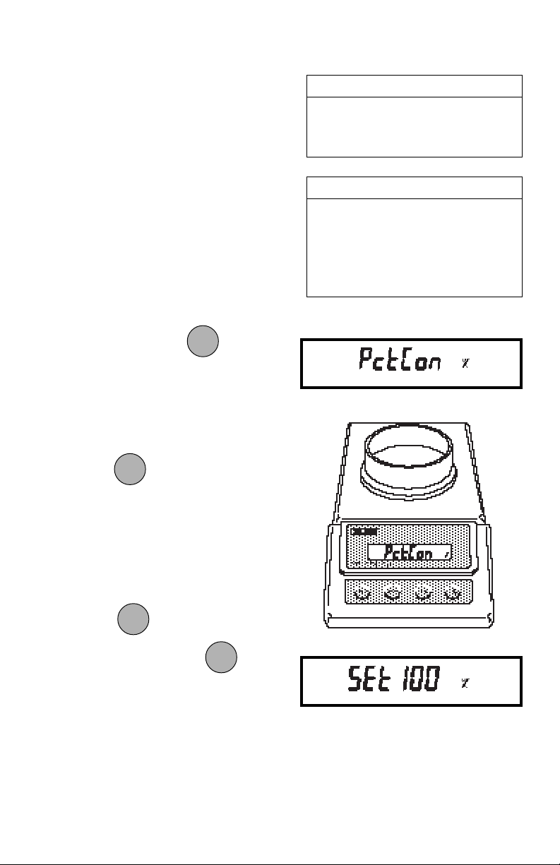
Percent WeighingPercent Weighing
Percent Weighing
Percent WeighingPercent Weighing
Percent weighing permits you to place a
reference load on the balance, then view
other loads as a percentage of the reference. The load you place on the pan as a
reference may be displayed as any percentage you select from 5% to 100% (in
1% increments). One hundred percent
does not necessarily have to represent
the reference load. Subsequent loads,
displayed as a percentage of the reference are limited only by the capacity of
the balance.
To perform percent weighing, use the
following procedure:
MODEMODE
MODE
1. Repeatedly press
MODEMODE
until PCT
CON is displayed.
2. Place an empty container on the pan
(if one will be used).
ONON
ON
3. Press
ONON
TARETARE
TARE
TARETARE
.
Percent Weighing Default SettingsPercent Weighing Default Settings
Percent Weighing Default Settings
Percent Weighing Default SettingsPercent Weighing Default Settings
% Mode................................ Disabled
% Alternate Display ........... TOTAL %
Reference %............................. 100%
EXAMPLEEXAMPLE
EXAMPLE
EXAMPLEEXAMPLE
A 10g reference load is set for 20%:
• A subsequent load of 100 g will be
displayed as 200%.
• A subsequent load of 200 g will be
displayed as 400%.
4. SEt xxx will be displayed where xxx is
the current reference percentage.
5. The reference percentage can be
changed to any value from 5 to 100.
MODEMODE
MODE
Press
(Pressing and holding causes
MODEMODE
to change the value.
MODEMODE
MODE
MODEMODE
the display to increment quickly.)
15
Page 69
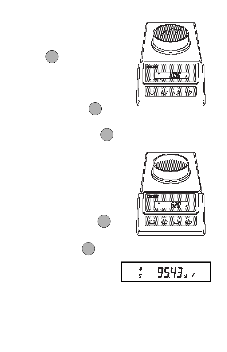
6. Place the reference load in the container (or directly on the pan if no
container is used).
ONON
ON
ONON
7. Press
TARETARE
TARE
TARETARE
.
8. The display will show the reference
load as the percentage you selected.
NOTE: NOTE:
NOTE: To exit or restart percent weighing
NOTE: NOTE:
ONON
ON
ONON
at any time, press and hold
TARETARE
TARE
TARETARE
until
PCT CON is displayed, then release it.
MODEMODE
MODE
Return to step 2 to restart, or press
MODEMODE
to change to another weighing mode.
9. Remove the reference load from the
balance and replace it with another
load.
10. The second load will be displayed as
a percentage of the reference.
The reference weight may be viewed at
PRINTPRINT
PRINT
any time by pressing and holding
PRINTPRINT
To view the weight or gross percentage of
MODEMODE
MODE
the load on the pan, press
MODEMODE
.
Weight will be displayed in the weighing
unit selected in PCTT ALT in the Setup
menu.
.
16
Page 70
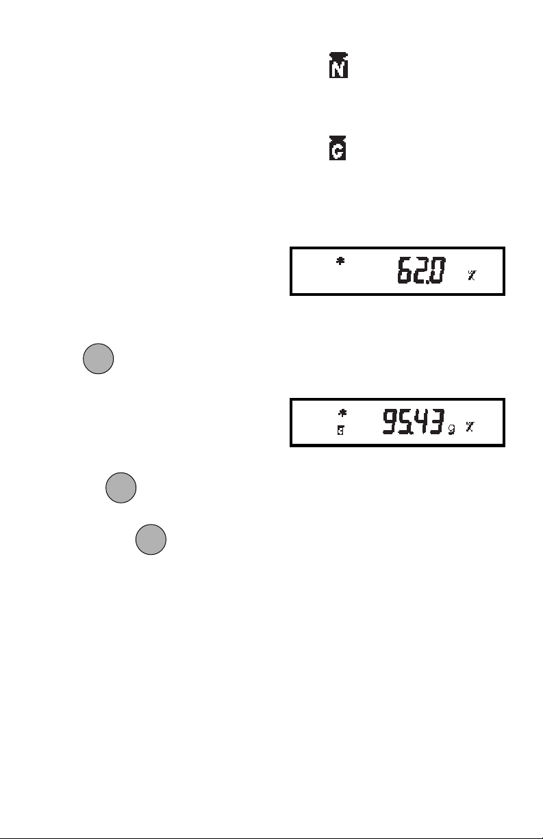
IF NETIF NET
IF NET has been selected for the alternate
IF NETIF NET
display, you may repeatedly tare the balance between weighings. The alternate
display will show the net weight of material added since the last tare.
Lights to indicate NET.
IF TOTALIF TOTAL
IF TOTAL has been selected for the alter-
IF TOTALIF TOTAL
nate display, the balance will display the
gross weight (relative to weight of container already tared) or percentage of
material on the pan. Taring will not affect
the alternate display.
NOTE:NOTE:
NOTE: The primary percentage display
NOTE:NOTE:
always shows the NET percentage.
To switch between the alternate display
and the percentage display, repeatedly
MODEMODE
MODE
MODEMODE
press
NOTE:NOTE:
NOTE: You may change the alternate
NOTE:NOTE:
.
display unit through the Setup menu without losing the current reference.
To exit or restart percent weighing, press
MODEMODE
MODE
and hold
MODEMODE
until PCT CON is dis-
played, then release it. Return to step 2 to
Lights to indicate TOTAL
or Gross.
Percent Display
Alternate Display
MODEMODE
MODE
restart, or press to change to anoth-
MODEMODE
er weighing mode.
17
Page 71
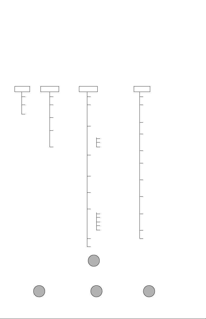
USING MENUS TO CONFIGURE THE BALANCEUSING MENUS TO CONFIGURE THE BALANCE
USING MENUS TO CONFIGURE THE BALANCE
USING MENUS TO CONFIGURE THE BALANCEUSING MENUS TO CONFIGURE THE BALANCE
Precision Plus balances contain four display menus which enable you to calibrate and
configure the balance for your specific operating requirements.
Calibration Menu:Calibration Menu:
Calibration Menu: Used to calibrate the balance for span or linearity.
Calibration Menu:Calibration Menu:
User Menu:User Menu:
User Menu: Used to adapt the balance to environmental conditions.
User Menu:User Menu:
Setup Menu:Setup Menu:
Setup Menu: Used to enable or disable different balance features.
Setup Menu:Setup Menu:
Print Menu:Print Menu:
Print Menu: Used to configure the RS232 interface.
Print Menu:Print Menu:
CAL
SPAN
LINEARITY
END
USER
RESET
AL
STABILITY
AUTO ZERO
END
11
0,
1, 2, 3
11
.5d,
OFF,
3d
1d1d
1d, 2d, 5d
1d1d
.5d.5d
.5d, 1d,
.5d.5d
SETUP
RESET
UNIT SELECTION
gg
g, dwt, ct, oz, oz t,
gg
GN, t, :, lb, lb:oz, cu,
PC, %
CUSTOM UNIT
CONVERSION
FACTOR
Mantissa
Exponent
LSD
PARTS COUNTING
ERROR LEVEL
OFFOFF
OFF, .1, .25, .5, 1,
OFFOFF
2.5, 5
PARTS COUNTING
ALTERNATE DISPLAY
Total piecesTotal pieces
Total pieces, Net
Total piecesTotal pieces
PERCENT WEIGHING
ALTERNATE DISPLAY
Total %Total %
Total %, Net
Total %Total %
LOCK SWITCH
Cal
User
Setup
Print
End
LIST MENU SETTINGS
End
PRINT
RESET
BAUD
300, 1200,
4800, 9600
DATA BITS
77
7 or 8
77
PARITY BIT
Odd, Even,
1, 0
STOP BITS
22
1 or
2
22
AUTO PRINT
continuous, interval
on stability,
INITIALIZE AUTO PRINT
Interval, Nonprint Lo,
Nonprint Hi
STABLE DATA
OUTPUT ONLY
NUMERIC DATA
OUTPUT ONLY
LIST MENU SETTINGS
End
ON or
ON or
OFFOFF
OFF
OFFOFF
OFFOFF
OFF
OFFOFF
24002400
2400,
24002400
NoneNone
None,
NoneNone
OFFOFF
OFF
OFFOFF
ONON
ON
To access a menu, press and hold until desired menu appears, then release it.
ONON
TARETARE
TARE
TARETARE
Original factory default settings are shown in boldface type. Use these buttons to
step through menus and select submenus:
PRINTPRINT
PRINT
PRINTPRINT
previous
selection
MODEMODE
MODE
MODEMODE
next
selection
ONON
ON
ONON
TARETARE
TARE
TARETARE
select
displayed item
18
Page 72
CALIBRATION MENUCALIBRATION MENU
CALIBRATION MENU
CALIBRATION MENUCALIBRATION MENU
Precision Plus balances can be calibrated in two ways: Span calibration or Linearity
calibration. Span calibration resets the balance’s weighing range using two weight
values: zero and a weight value at or near the balance’s capacity. Linearity calibration
minimizes deviation between actual and displayed weights within the balance’s
weighing range. Three weight values are used: zero, a weight value within the
balances weighing range, and a weight value at or near the balance’s specified
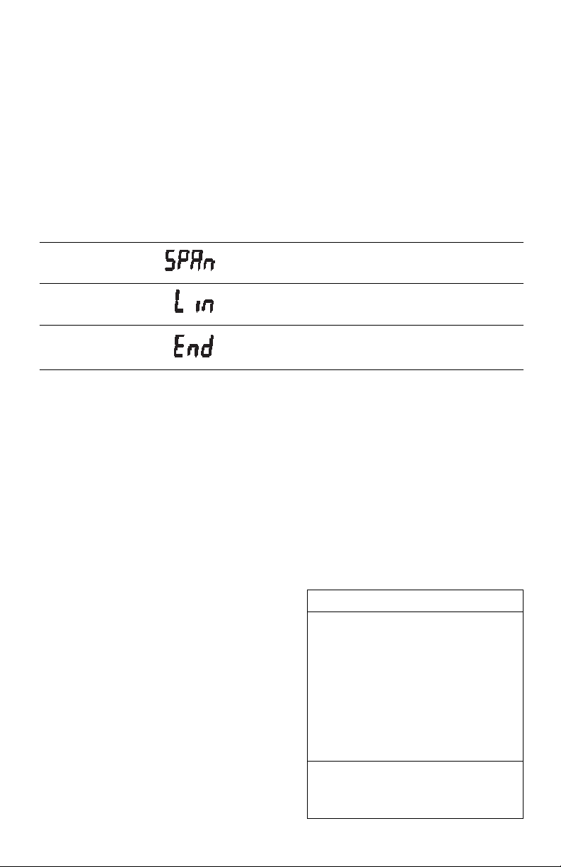
capacity. The following table shows the sequence in which submenus appear on the
Calibration menu.
CALIBRATION MENU TABLECALIBRATION MENU TABLE
CALIBRATION MENU TABLE
CALIBRATION MENU TABLECALIBRATION MENU TABLE
Selects span calibration.
Selects linearity calibration.
Used to exit the Calibration menu.
Calibration Menu ProtectionCalibration Menu Protection
Calibration Menu Protection
Calibration Menu ProtectionCalibration Menu Protection
Calibration may be locked out to prevent
unauthorized personnel from changing
calibration. To lock out calibration menu,
refer to the section titled Menu Lock-Out
Protection.
NOTENOTE
NOTE: If calibration has been locked out,
NOTENOTE
you will not be able to access it.
Calibration MassesCalibration Masses
Calibration Masses
Calibration MassesCalibration Masses
Before beginning calibration, make sure
masses are on hand. If you begin calibration and realize masses are not available,
either turn the balance off, or go through
the procedure without masses. The balance will use previously stored calibration
data. Calibration should be performed as
necessary to ensure accurate weighing.
Masses required to perform the procedures are listed in the adjacent table.
CALIBRATION WEIGHTSCALIBRATION WEIGHTS
CALIBRATION WEIGHTS
CALIBRATION WEIGHTSCALIBRATION WEIGHTS
LINEARITYLINEARITY
LINEARITY
MODELMODEL
MODEL
MODELMODEL
LINEARITYLINEARITY
MASSESMASSES
MASSES
MASSESMASSES
TP200 100g, 200g 200g
TP400 200g, 400g 400g
TP400D 50g, 400g 400g
TP600 200g, 500g 500g
TP2K 1kg, 2kg 2k g
TP4K 2kg, 4kg 4k g
TP4KD 500g, 4kg 4kg
Masses must meet or exceed ASTM
Class 1 Tolerance. Calibration masses
are available as accessories.
19
SPAN ONLYSPAN ONLY
SPAN ONLY
SPAN ONLYSPAN ONLY
MASSMASS
MASS
MASSMASS
Page 73
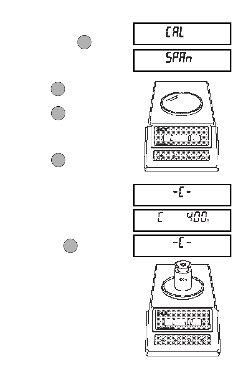
Span CalibrationSpan Calibration
Span Calibration
Span CalibrationSpan Calibration
ONON
ON
1. Press and hold until CAL is
ONON
TARETARE
TARE
TARETARE
displayed, then release it. Balance
will display SPAN.
ONON
ON
2. Press
3. When
ONON
.
TARETARE
TARE
TARETARE
ONON
ON
ONON
is released, C 0g will
TARETARE
TARE
TARETARE
be displayed indicating that no weight
should be on the pan.
ONON
ON
4. Press
ONON
. The display will show
TARETARE
TARE
TARETARE
-C- followed by the value of the weight
which must be placed on the pan.
NOTE: NOTE:
NOTE: Do not disturb the balance when
NOTE: NOTE:
-C- is displayed. Disturbances will result
in improper calibration.
5. Place the required weight on the pan
ONON
ON
ONON
and press
. The display will
TARETARE
TARE
TARETARE
show -C- while the balance
recalibrates.
6. When the weight on the pan is displayed along with the current unit
indicator, the balance is recalibrated.
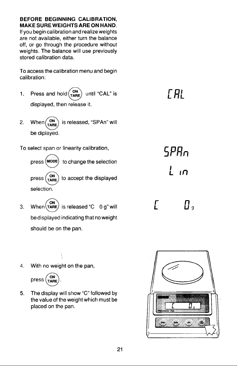
20
Page 74
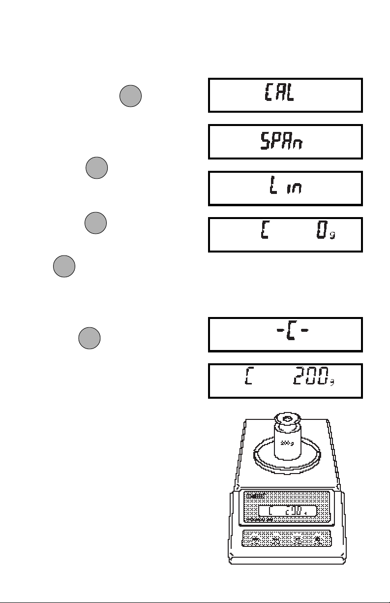
Linearity CalibrationLinearity Calibration
Linearity Calibration
Linearity CalibrationLinearity Calibration
1. Turn Balance on. After zero reading,
ONON
ON
ONON
press and hold
until CAL is
TARETARE
TARE
TARETARE
displayed, then release. Balance will
display SPAN.
MODEMODE
MODE
MODEMODE
2. Press
and the display will
show LIN.
ONON
ON
ONON
3. Press
to start the Linearity
TARETARE
TARE
TARETARE
Calibration Procedure. When the
ONON
ON
ONON
is released, C 0g will be
TARETARE
TARE
TARETARE
displayed, indicating that no weight
should be in the pan.
ONON
ON
4. Press . The display will show
ONON
TARETARE
TARE
TARETARE
-C- followed by the value of the weight
which must be placed on the pan.
5. Place the required weight on the pan.
21
Page 75
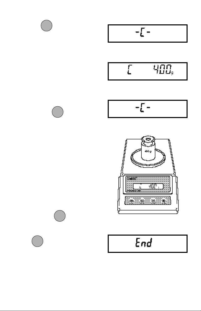
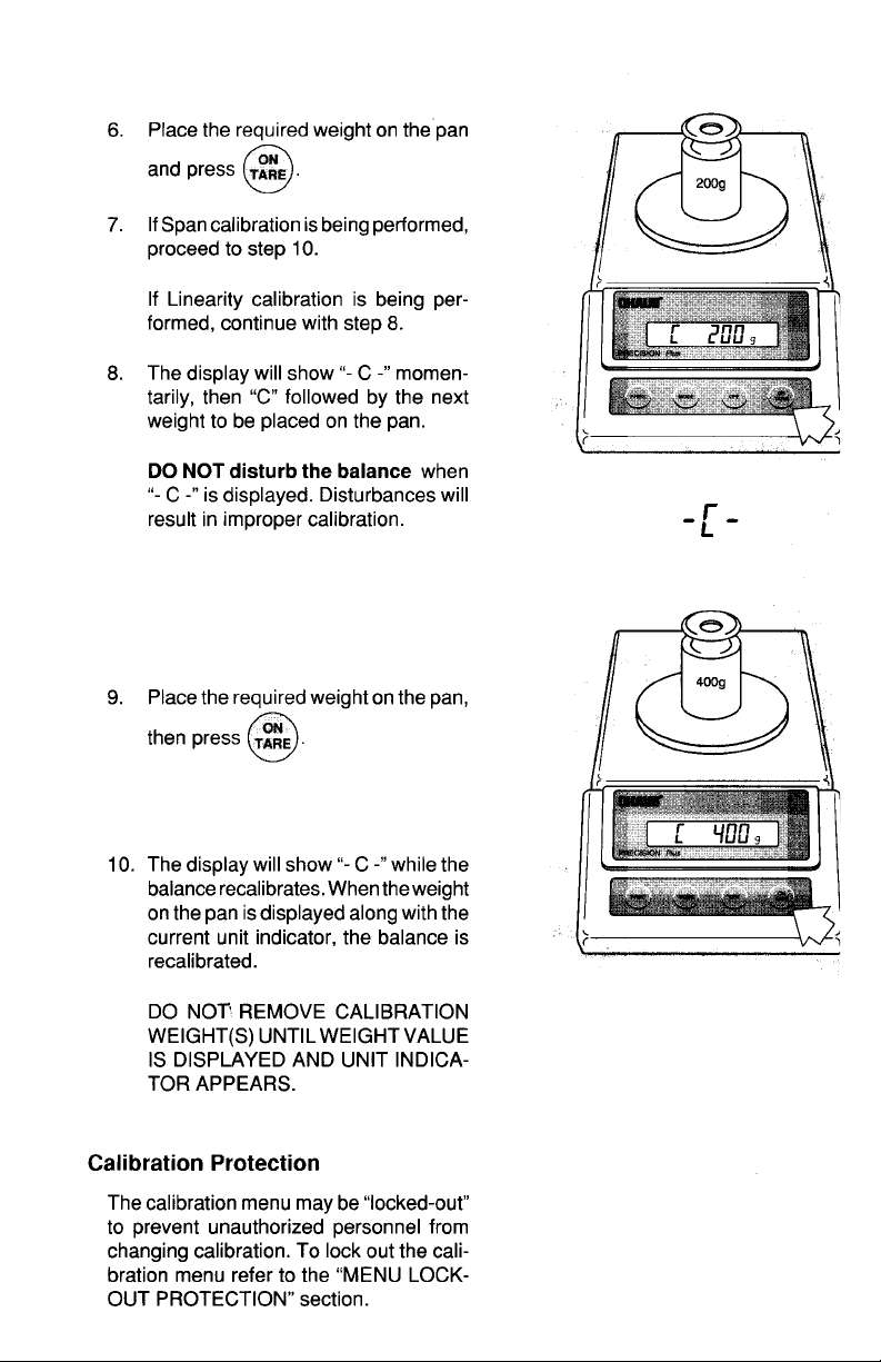
ONON
ON
6. Press . The display will show
ONON
TARETARE
TARE
TARETARE
-C- momentarily, then C followed by
the next weight to be placed on the
pan. Do not disturb the balance when
-C- is displayed. Disturbances will
result in improper calibration.
7. Place the required weight on the pan,
ONON
ON
then press
ONON
. The display will
TARETARE
TARE
TARETARE
show -C- while the balance
recalibrates. When the weight on the
pan is displayed along with the current indicator, the balance is
recalibrated.
EndEnd
End
EndEnd
If you have entered the Calibration menu
and do not wish to calibrate the balance,
use END to return to normal weighing
operations.
MODEMODE
MODE
Repeately press
MODEMODE
until END is dis-
played.
ONON
ON
ONON
Press
, when released, the balance
TARETARE
TARE
TARETARE
will returned to normal weighing operations.
22
Page 76
USER MENUUSER MENU
USER MENU
USER MENUUSER MENU
The User menu is used to adapt the balance to environmental conditions. It contains
submenus which enable you to reset the balance to factory default settings or to select
specific range settings. Access to the User menu can be disabled using the Lock Out
switch. The following table shows the sequence in which submenus appear on the
User menu.
USER MENU TABLEUSER MENU TABLE
USER MENU TABLE
USER MENU TABLEUSER MENU TABLE
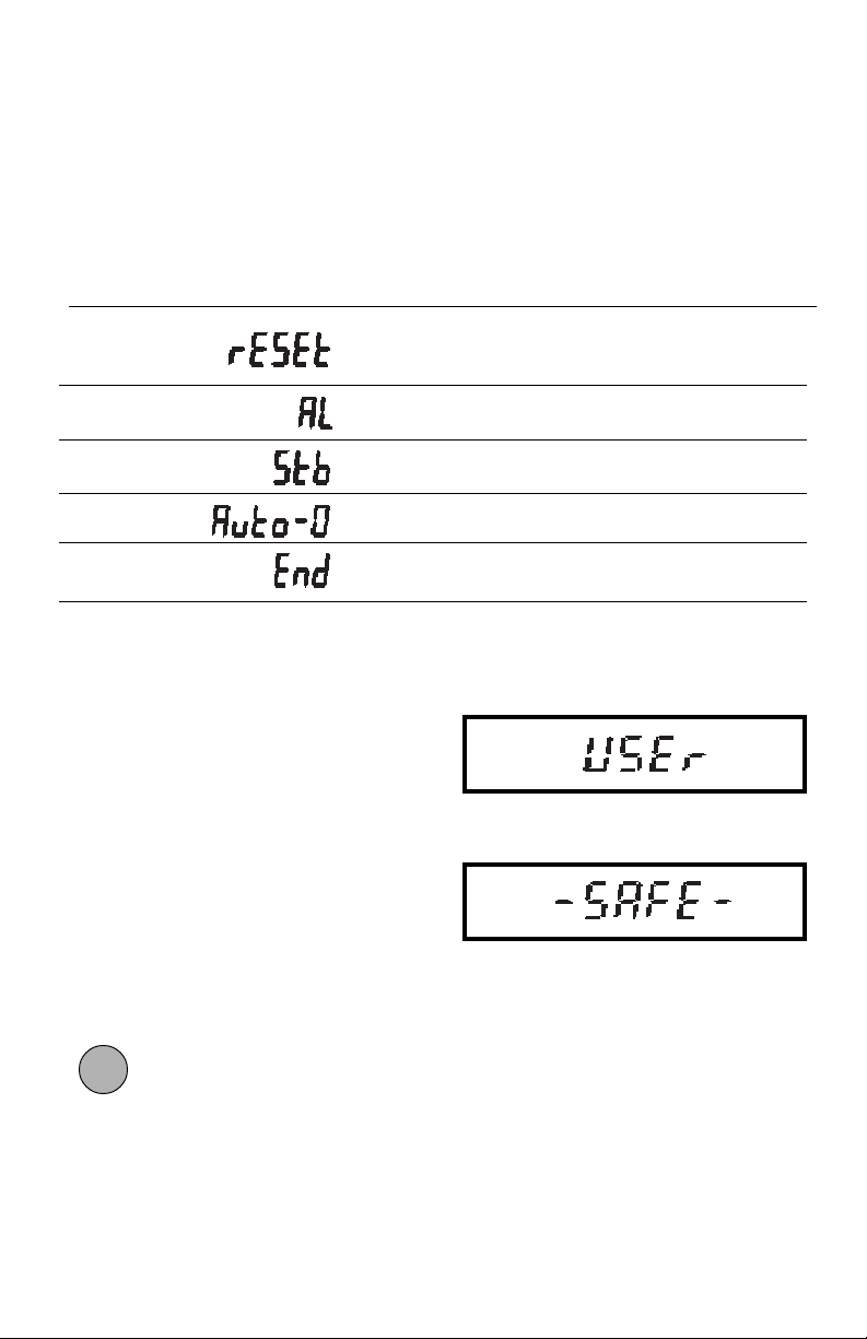
Sets all submenus below to original
factory default settings. Reset does not
appear if menu has been locked out.
Specifies the averaging level.
Specifies the desired stability range.
Sets Auto-Zero threshold.
Used to exit the Setup menu and store
your selections.
User Menu ProtectionUser Menu Protection
User Menu Protection
User Menu ProtectionUser Menu Protection
The User menu may be locked out to
prevent unauthorized personnel from
changing the settings. To lock out the
User menu, refer to the section titled Menu
Lock-Out Protection.
NOTENOTE
NOTE: If -SAFE- is displayed, the User
NOTENOTE
menu has been locked out. Settings may
be viewed but not changed. See the Menu
Lock-Out Protection section to enable it
for making changes.
To access the User menu, press and hold
ONON
ON
ONON
until USER is displayed, then re-
TARETARE
TARE
TARETARE
lease it.
23
Page 77
To access a submenu:
MODEMODE
MODE
1. Repeatedly press
MODEMODE
until the de-
sired submenu is displayed.
ONON
ON
2. Press
ONON
to select the displayed
TARETARE
TARE
TARETARE
submenu.
NOTENOTE
NOTE: You must use END to store any
NOTENOTE
changes you make to the User menu.
The following sections describe each item
on the User menu in detail.
Reset to Factory DefaultsReset to Factory Defaults
Reset to Factory Defaults
Reset to Factory DefaultsReset to Factory Defaults
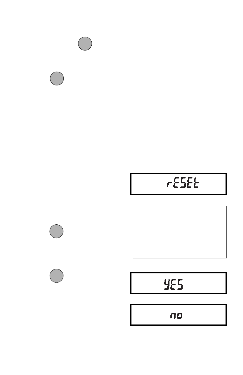
This submenu enables you to reset all
User menu selections to the factory default settings outlined in the adjacent table.
To reset to factory defaults:
1. Access the Reset submenu.
MODEMODE
MODE
2. Press
MODEMODE
to change the setting.
Select YES to reset settings or,
no to leave current settings.
ONON
ON
Press
ONON
to accept the displayed
TARETARE
TARE
TARETARE
setting.
USER MENUUSER MENU
USER MENU
USER MENUUSER MENU
FACTORY DEFAULTSFACTORY DEFAULTS
FACTORY DEFAULTS
FACTORY DEFAULTSFACTORY DEFAULTS
Averaging Level AL 1
Stability Range 1d
Auto-Zero Tracking .5d
24
Page 78
Averaging LevelAveraging Level
Averaging Level
Averaging LevelAveraging Level
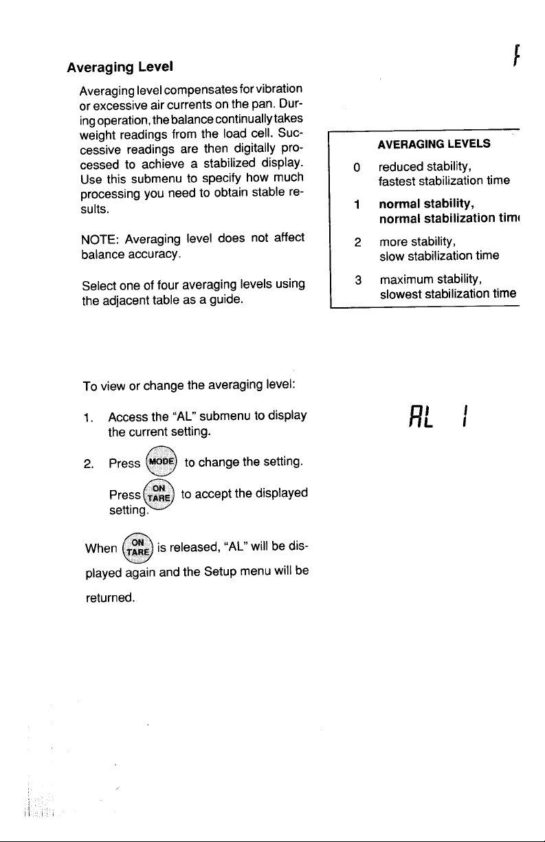
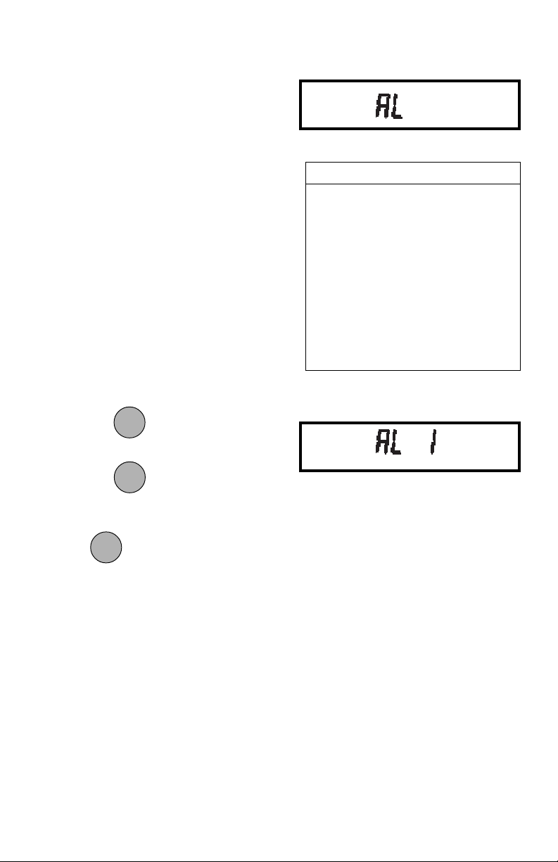
Averaging level compensates for vibration or excessive air currents. During operation, the balance continually takes
weight readings from the weighing cell.
Successive readings are then digitally processed to achieve a stabilized display.
Use this submenu to specify how much
processing you need to obtain stable results.
NOTE: Averaging level does not affect
balance accuracy.
AVERAGING LEVELAVERAGING LEVEL
AVERAGING LEVEL
AVERAGING LEVELAVERAGING LEVEL
AL 0 reduced stability, fastest
stabilization time
ALAL
1 normal stability, normal1 normal stability, normal
AL
1 normal stability, normal
ALAL
1 normal stability, normal1 normal stability, normal
stabilization timestabilization time
stabilization time
stabilization timestabilization time
Select one of four averaging levels using
the adjacent table as a guide.
To view or change the averaging level:
1. Access the AL submenu to display
the current setting.
MODEMODE
MODE
2. Press
MODEMODE
to change the setting.
ONON
ON
Press to accept the displayed
ONON
TARETARE
TARE
TARETARE
setting.
ONON
ON
When
ONON
is released, AL will be dis-
TARETARE
TARE
TARETARE
played again and the Setup menu will be
returned.
AL 2 more stability, slow stabi-
lization time
AL 3 maximum stability, slow-
est stabilization time
25
Page 79
Stability RangeStability Range
Stability Range
Stability RangeStability Range
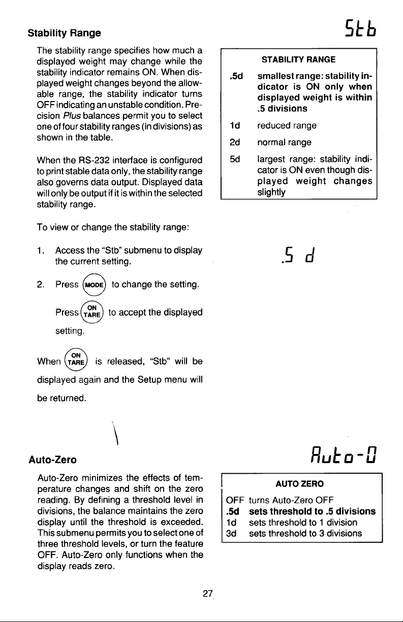
The stability range specifies how much a
displayed weight may change while the
stability indicator remains ON. When displayed weight changes beyond the allowable range, the stability indicator turns
OFF indicating an unstable condition. Precision Plus balances permit you to select
one of four stability ranges (in divisions)
as shown in the table.
When the RS232 interface is configured
to print stable data only, the stability range
also governs data output. Displayed data
will only be output if it is within the selected
stability range.
To view or change the stability range:
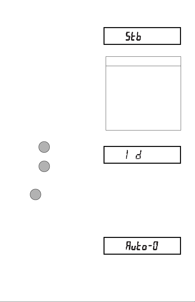
1. Access the Stb submenu to display
the current setting.
MODEMODE
MODE
2. Press
MODEMODE
to change the setting.
STABILITY RANGESTABILITY RANGE
STABILITY RANGE
STABILITY RANGESTABILITY RANGE
..
.5d Smallest range: stability indi-
..
cator is ON only when displayed weight is within .5 divisions.
1d1d
Reduced range.Reduced range.
1d
Reduced range.
1d1d
Reduced range.Reduced range.
2d Normal range.
5d Largest range: stability indi-
cator is ON even though displayed weight changes
slightly.
ONON
ON
ONON
Press
to accept the displayed
TARETARE
TARE
TARETARE
setting.
ONON
ON
When
ONON
is released, STB will be dis-
TARETARE
TARE
TARETARE
played again and the Setup menu will be
returned.
Auto-ZeroAuto-Zero
Auto-Zero
Auto-ZeroAuto-Zero
Auto-Zero minimizes the effects of temperature changes and shift on the zero
reading. By defining a threshold level in
divisions, the balance maintains the zero
display until the threshold is exceeded.
This submenu permits you to select one of
three threshold levels, or turn the feature
OFF. Auto-Zero only functions when the
display reads zero.
26
Page 80
To view or change the Auto-Zero setting:
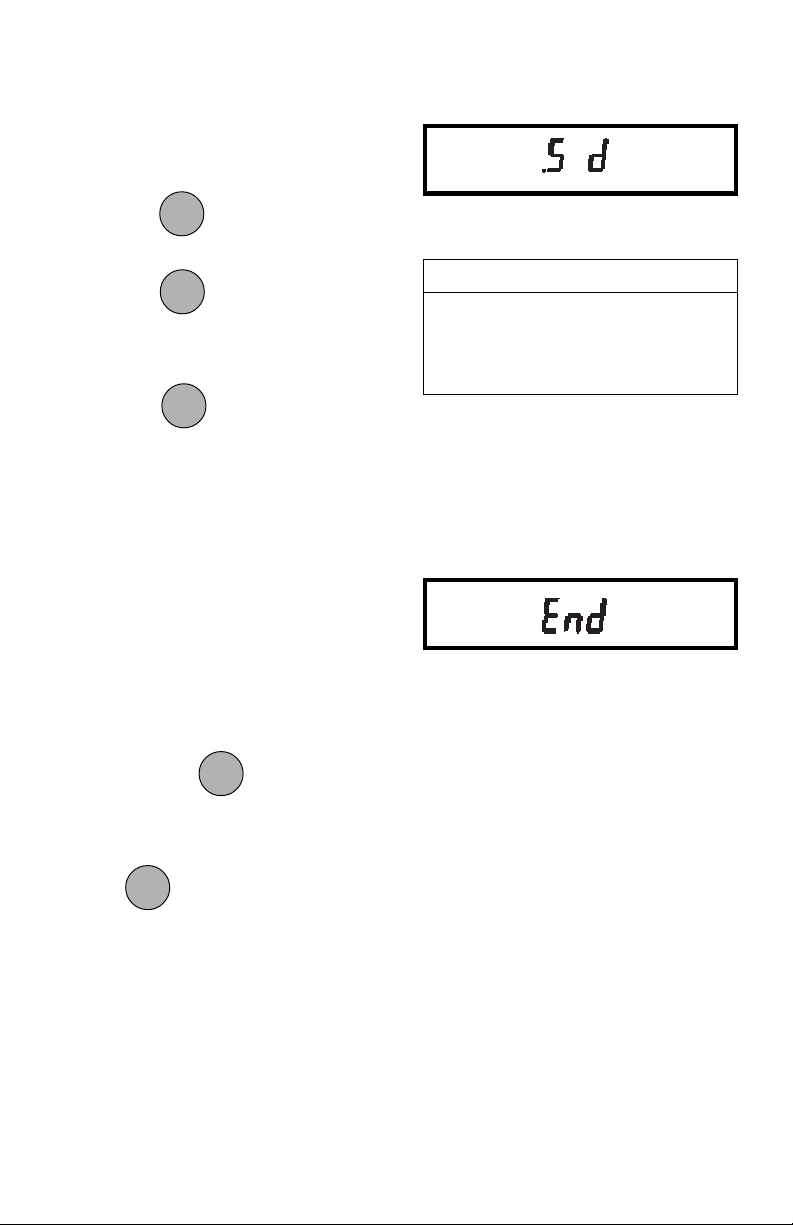
1. Access the Auto-0 submenu to display the current setting.
MODEMODE
MODE
2. Press
MODEMODE
to change the setting.
ONON
ON
ONON
TARETARE
TARE
Press
TARETARE
to accept the displayed
setting.
ONON
ON
When
ONON
is released, Auto-0 will
TARETARE
TARE
TARETARE
be displayed again and the User menu
will be returned.
EndEnd
End
EndEnd
You must use END to exit the User menu.
Changes you make in the User menuChanges you make in the User menu
Changes you make in the User menu
Changes you make in the User menuChanges you make in the User menu
are only stored in memory if you useare only stored in memory if you use
are only stored in memory if you use
are only stored in memory if you useare only stored in memory if you use
END. END.
END. To exit without storing changes,
END. END.
press OFF.
To exit the User menu and store your
ONON
ON
ONON
settings, press
when END is dis-
TARETARE
TARE
TARETARE
played.
AUTO ZEROAUTO ZERO
AUTO ZERO
AUTO ZEROAUTO ZERO
OFF Turns Auto-Zero OFF.
.5d.5d
Sets threshold to .5 divisions.Sets threshold to .5 divisions.
.5d
Sets threshold to .5 divisions.
.5d.5d
Sets threshold to .5 divisions.Sets threshold to .5 divisions.
1d Sets threshold to 1 division.
3d Sets threshold to 3 divisions.
ONON
ON
When
ONON
is released, the balance will
TARETARE
TARE
TARETARE
be returned to normal weighing operations.
27
Page 81
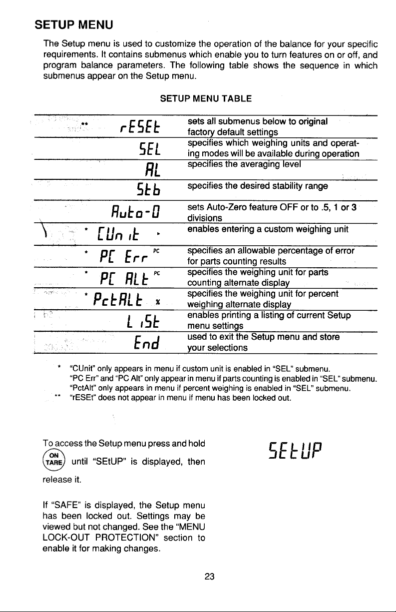
SETUP MENUSETUP MENU
SETUP MENU
SETUP MENUSETUP MENU
The Setup menu is used to customize the operation of the balance for your specific
requirements. It contains submenus which enable you to turn features on or off, and
program balance parameters. The following table shows the sequence in which
submenus appear on the Setup menu.
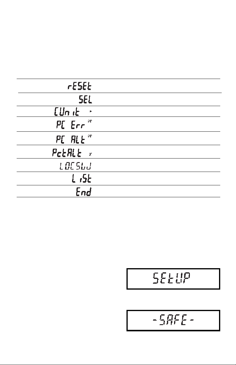
SETUP MENU TABLESETUP MENU TABLE
SETUP MENU TABLE
SETUP MENU TABLESETUP MENU TABLE
*
**
**
**
**
* RESET does not appear in menu if menu has been locked out.
* * CUNIT only appears in menu if custom unit is enabled in SEL submenu.
PC ERR and PC Alt only appear in menu if parts counting is enabled in SEL submenu.
PCTALT only appears in menu if percent weighing is enabled in SEL submenu.
Sets all submenus below to original
factory default settings.
Specifies which weighing units and operating modes will be available during operation.
Enables entering a custom weighing unit.
Specifies an allowable percentage of error
for parts counting results.
Specifies the weighing unit for parts
counting alternate display.
Specifies the weighing unit for percent
weighing alternate display.
Enables individual or all menus to be
locked out.
Enables printing a listing of current Setup
menu settings.
Used to exit the Setup menu and store
your selections.
Setup Menu ProtectionSetup Menu Protection
Setup Menu Protection
Setup Menu ProtectionSetup Menu Protection
The Setup menu may be locked out to
prevent unauthorized personnel from
changing settings. To lock out the Setup
menu, refer to the section titled Menu
Lock-Out Protection.
NOTENOTE
NOTE: If -SAFE- is displayed, the Setup
NOTENOTE
menu has been locked out. Settings may
be viewed but not changed. See the Menu
Lock-Out Protection section to enable it
for making changes.
28
Page 82
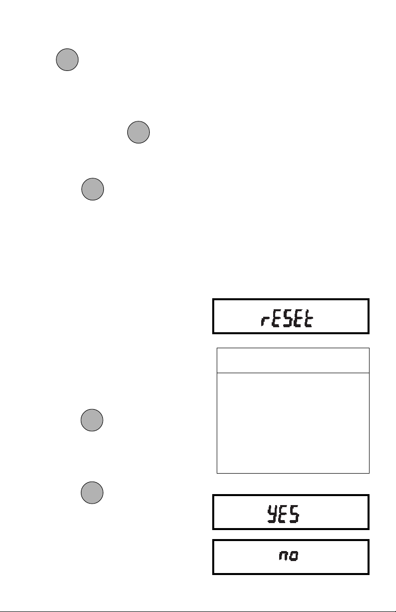
To access the Setup menu, press and
ONON
ON
ONON
hold
until SETUP is displayed, then
TARETARE
TARE
TARETARE
release it.
To access a submenu:
MODEMODE
MODE
1. Repeatedly press
MODEMODE
until the de-
sired submenu is displayed.
ONON
ON
2. Press
ONON
to select the displayed
TARETARE
TARE
TARETARE
submenu.
NOTE:NOTE:
NOTE: You must use END to store any
NOTE:NOTE:
changes you make to the Setup menu.
The following sections describe each item
on the Setup menu in detail.
Reset to Factory DefaultsReset to Factory Defaults
Reset to Factory Defaults
Reset to Factory DefaultsReset to Factory Defaults
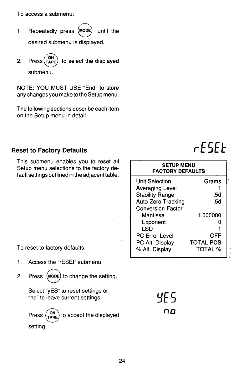
This submenu enables you to reset all
Setup menu selections to the factory default settings outlined in the adjacent table.
To reset to factory defaults:
1. Access the Reset submenu.
2. Press to change the setting.
MODEMODE
MODE
MODEMODE
Select YES to reset settings or,
no to leave current settings.
SETUP MENUSETUP MENU
SETUP MENU
SETUP MENUSETUP MENU
FACTORY DEFAULTSFACTORY DEFAULTS
FACTORY DEFAULTS
FACTORY DEFAULTSFACTORY DEFAULTS
Unit Selection On g
Conversion Factor
Mantissa 1.000000
Exponent 0
LSD 1
PC Error Level OFF
PC Alt. Display TOTAL PCS
% Alt. Display TOTAL %
Press
setting.
ONON
ON
ONON
to accept the displayed
TARETARE
TARE
TARETARE
29
Page 83
Unit SelectionUnit Selection
Unit Selection
Unit SelectionUnit Selection
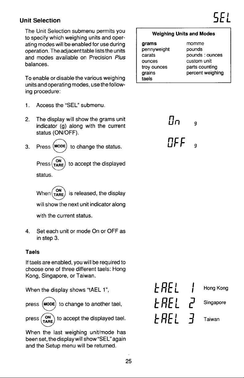
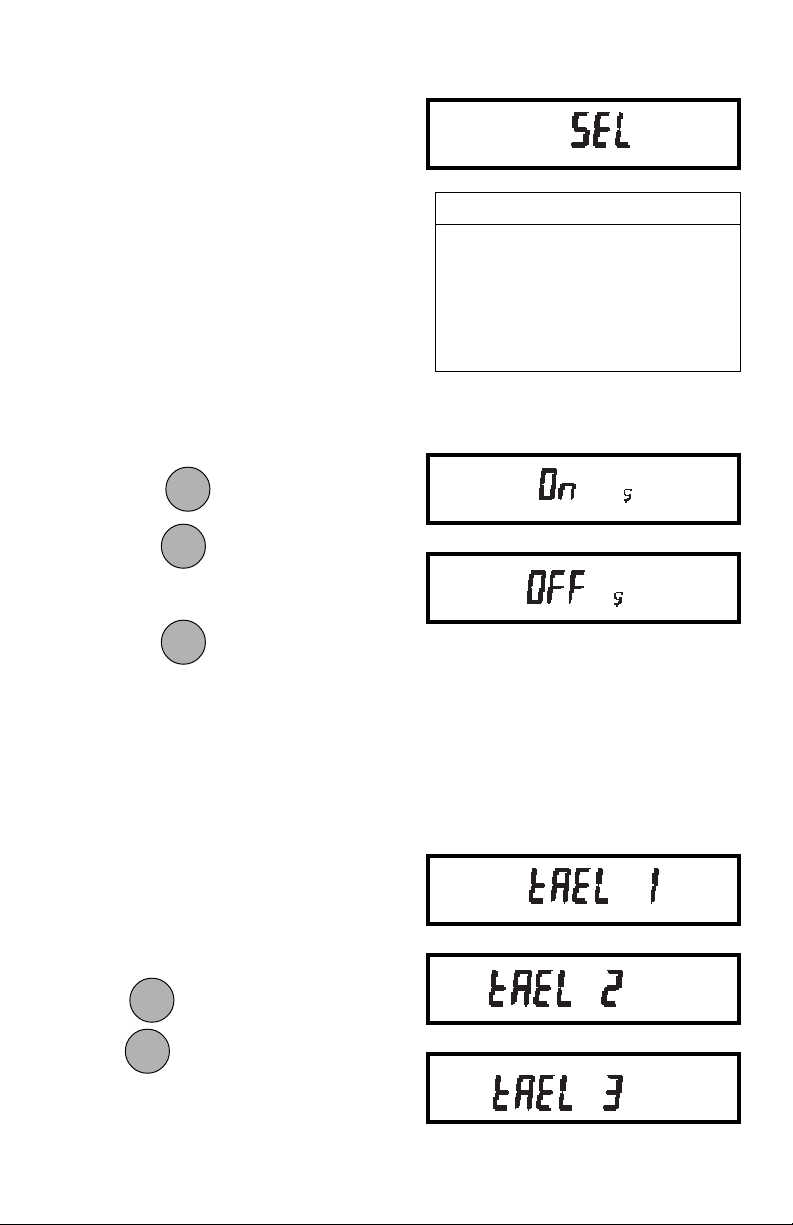
The Unit Selection submenu permits you
to specify which weighing units and operating modes will be enabled for use during
operation. The adjacent table lists the
units and modes available on Precision
Plus balances.
To enable or disable the various weighing
units and operating modes, use the following procedure:
1. Access the Sel submenu.
2. The display will show the grams unit
indicator (g) along with the current
status (ON/OFF).
MODEMODE
MODE
3. Press MODE to change the status.
MODEMODE
ONON
ON
Press TARE to accept the displayed
ONON
TARETARE
TARE
TARETARE
status.
ONON
ON
When TARE is released, the display
ONON
TARETARE
TARE
TARETARE
will show the next unit indicator along
Weighing Units and ModesWeighing Units and Modes
Weighing Units and Modes
Weighing Units and ModesWeighing Units and Modes
gramsgrams
grams momme
gramsgrams
pennyweight pounds
carats pounds : ounces
ounces custom unit
troy ounces parts counting
grains percent weighing
taels
with the current status.
4. Set each unit or mode ON or OFF as
in step 3.
TaelsTaels
Taels
TaelsTaels
If taels are enabled, you will be required to
choose one of three different taels: Hong
Kong, Singapore, or Taiwan.
When the display shows TAEL 1,
MODEMODE
MODE
MODEMODE
press MODE to change to another tael,
ONON
ON
press TARE to accept the displayed tael.
ONON
TARETARE
TARE
TARETARE
When the last weighing unit/mode has
been set, the display will show SEL again
and the Setup menu will be returned.
Hong Kong
Singapore
Taiwan
30
Page 84
Custom Unit Conversion FactorCustom Unit Conversion Factor
Custom Unit Conversion Factor
Custom Unit Conversion FactorCustom Unit Conversion Factor
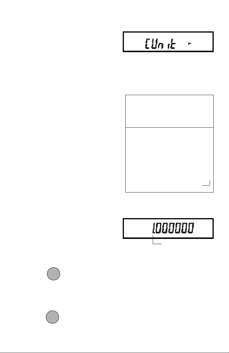
When you need to display weight measurements in a weighing unit other than
those provided standard with the balance,
this feature can be used to create your
own custom weighing unit. It permits you
to enter a conversion factor which the
balance will use to convert grams to the
desired unit of measure.
Conversion Weight Weight
Factor x in = in
grams custom unit
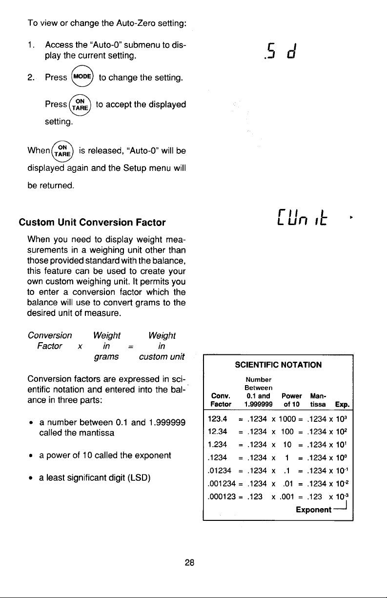
Conversion factors are expressed in scientific notation and entered into the balance in three parts:
• a number between 0.1 and 1.999999
called the mantissa
• a power of 10 called the exponent
• a least significant digit (LSD)
Use the following procedure to enter conversion factors:
SCIENTIFIC NOTATIONSCIENTIFIC NOTATION
SCIENTIFIC NOTATION
SCIENTIFIC NOTATIONSCIENTIFIC NOTATION
NumberNumber
Number
NumberNumber
BetweenBetween
Between
Conv.Conv.
Conv.
Conv.Conv.
FactorFactor
Factor
FactorFactor
BetweenBetween
0.1 and0.1 and
0.1 and
0.1 and0.1 and
1.9999991.999999
1.999999
1.9999991.999999
PowerPower
Power
PowerPower
of 10of 10
of 10
of 10of 10
Man-Man-
Man-
Man-Mantissatissa
tissa
tissatissa
Exp.Exp.
Exp.
Exp.Exp.
123.4 = .1234 x 1000 = .1234 x 10
12.34 = .1234 x 100 = .1234 x 10
1.234 = .1234 x 10 = .1234 x 10
.1234 = .1234 x 1 = .1234 x 10
.01234 = .1234 x .1 = .1234 x 10
.001234 = .1234 x .01 = .1234 x 10
.000123 = .123 x .001 = .123 x 10
ExponentExponent
Exponent
ExponentExponent
3
2
1
0
-1
-2
-3
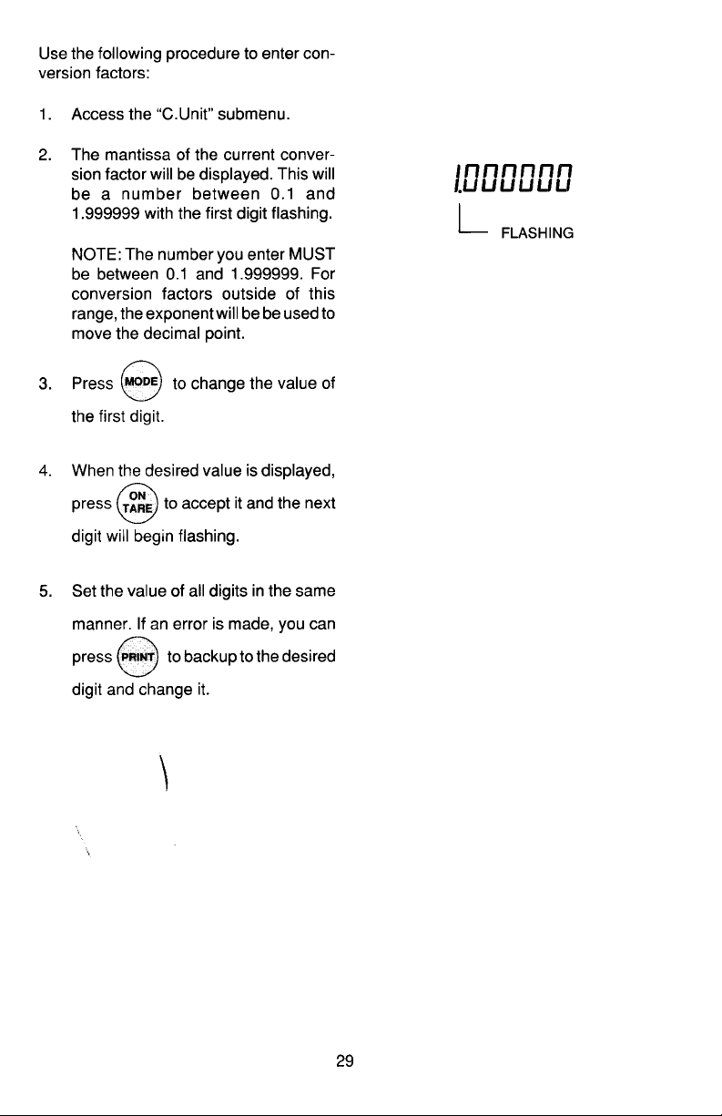
1. Access the C Unit submenu.
2. The mantissa of the current conversion factor will be displayed. This will
be a number between 0.1 and
1.999999 with the first digit flashing.
For conversion factors outside of this
range, the exponent will be be used
to move the decimal point.
MODEMODE
MODE
3. Press
MODEMODE
to change the value of
the first digit.
4. When the desired value is displayed,
ONON
ON
press
ONON
to accept it and the next
TARETARE
TARE
TARETARE
digit will begin flashing.
FLASHING
31
Page 85
5. Set the value of all digits in the same
manner. If an error is made, you can
PRINTPRINT
PRINT
PRINTPRINT
press
to backup to the desired
digit and change it.
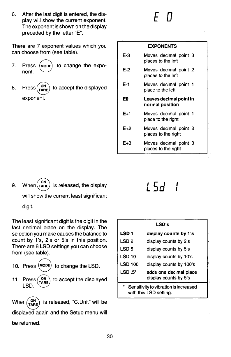
6. After the last digit is entered, the
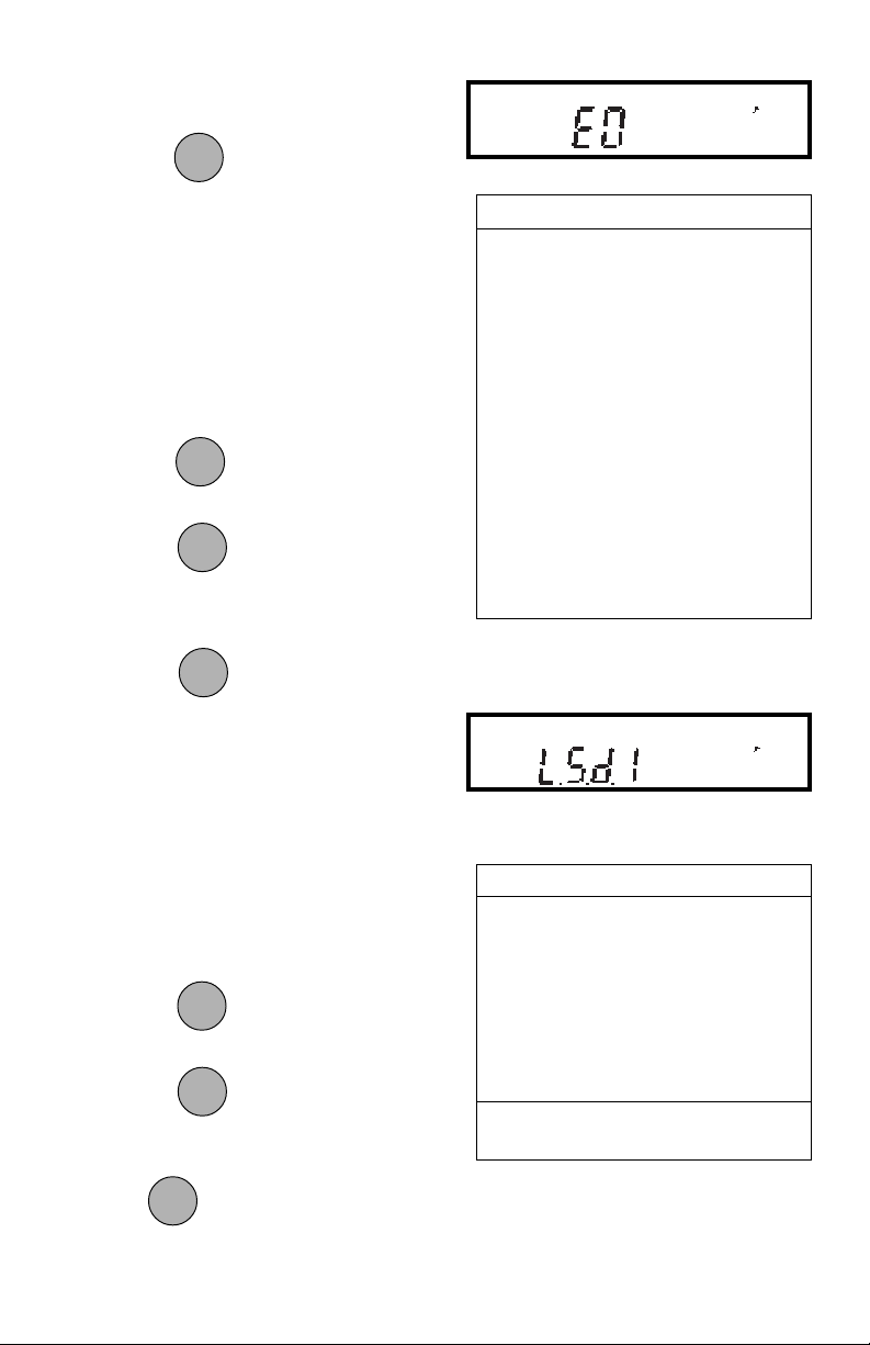
display will show the current exponent. The exponent is shown on the
display preceded by the letter E.
There are 7 exponent values which you
can choose from (see table).
MODEMODE
MODE
7. Press
8. Press
MODEMODE
to change the exponent.
ONON
ON
ONON
to accept the displayed
TARETARE
TARE
TARETARE
exponent.
ONON
ON
9. When
ONON
is released, the display
TARETARE
TARE
TARETARE
will show the current least significant
EXPONENTSEXPONENTS
EXPONENTS
EXPONENTSEXPONENTS
E-3 Moves decimal point 3
places to the left.
E-2 Moves decimal point 2
places to the left.
E-1 Moves decimal point 1
place to the left.
E0E0
E0
E0E0
Leaves decimal pointLeaves decimal point
Leaves decimal point
Leaves decimal pointLeaves decimal point
in normal position.in normal position.
in normal position.
in normal position.in normal position.
E1 Moves decimal point 1
place to the right.
E2 Moves decimal point 2
places to the right.
E3 Moves decimal point 3
places to the right.
digit.
The least significant digit is the digit in the
last decimal place on the display. The
selection you make causes the balance to
count by 1’s, 2’s or 5’s in this position.
There are 6 LSD settings you can choose
from (see table).
MODEMODE
MODE
10. Press
11. Press
MODEMODE
to change the LSD.
ONON
ON
ONON
to accept the displayed
TARETARE
TARE
TARETARE
LSD.
ONON
ON
When
ONON
is released, C Unit will be
TARETARE
TARE
TARETARE
displayed again and the Setup menu will
be returned.
LSD’sLSD’s
LSD’s
LSD’sLSD’s
LSD .5* Adds one decimal place
display counts by 5’s.
LSD 1LSD 1
LSD 1
LSD 1LSD 1
Display counts by 1’s.Display counts by 1’s.
Display counts by 1’s.
Display counts by 1’s.Display counts by 1’s.
LSD 2 Display counts by 2’s.
LSD 5 Display counts by 5’s.
LSD 10 Display counts by 10’s.
LSD 100 Display counts by 100’s.
* Sensitivity to vibration is increased
with this LSD setting.
32
Page 86
Parts Counting Error LevelParts Counting Error Level
Parts Counting Error Level
Parts Counting Error LevelParts Counting Error Level
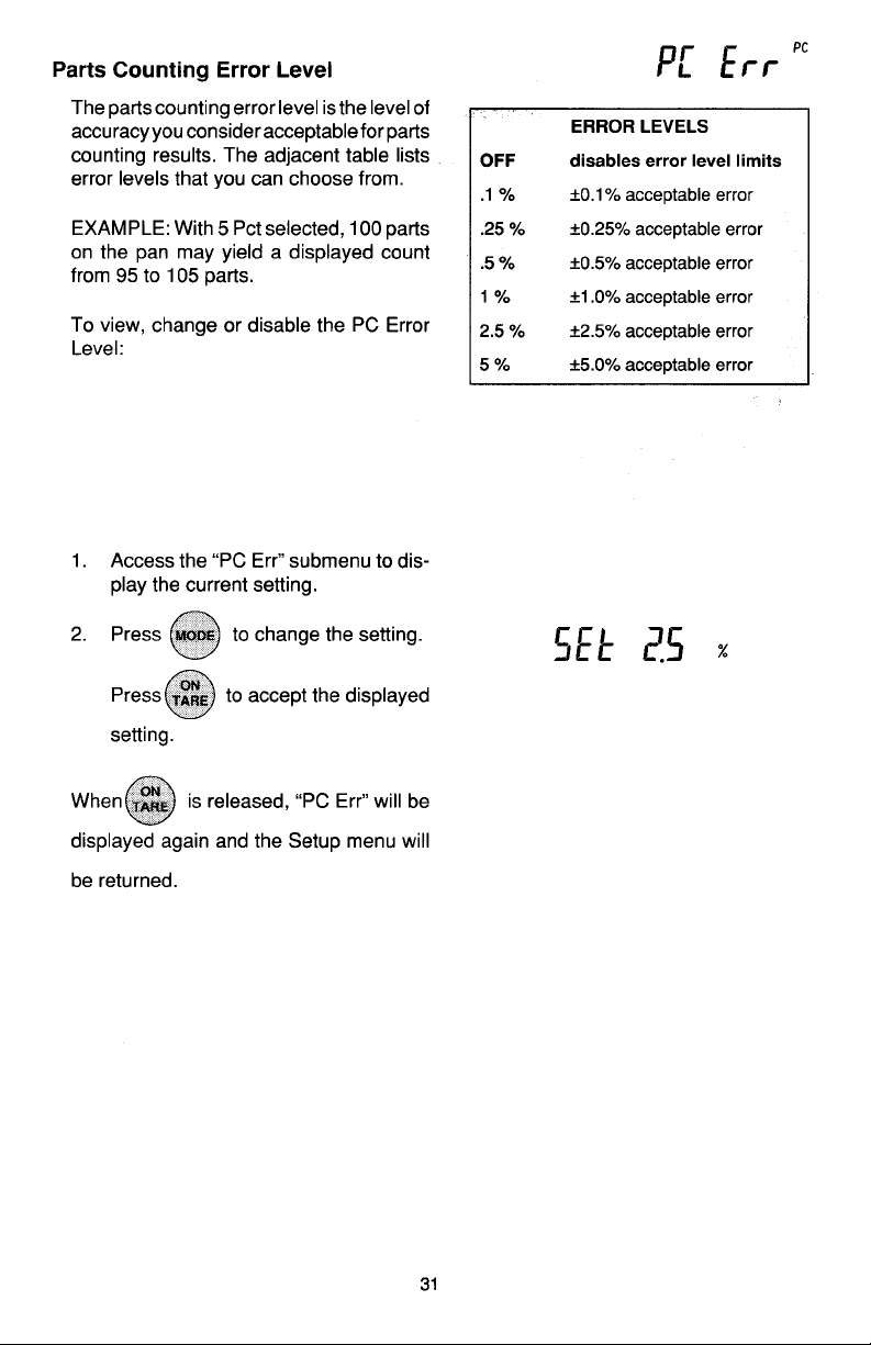
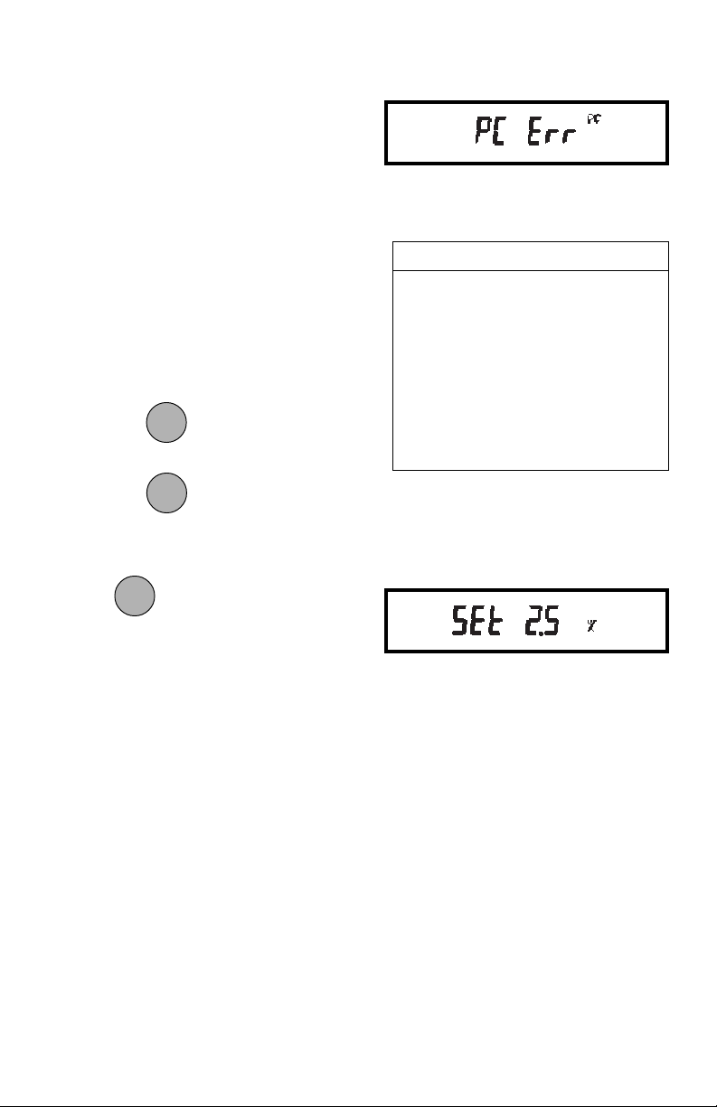
The parts counting error level is the level
of accuracy you consider acceptable for
parts counting results. The adjacent table
lists error levels that you can choose from.
EXAMPLE: With 5 Pct selected, 100 parts
on the pan may yield a displayed count
from 95 to 105 parts.
To view, change or disable the PC Error
Level:
1. Access the Pc Err submenu to display the current setting.
MODEMODE
MODE
Press
MODEMODE
to change the setting.
ONON
ON
ONON
to accept the displayed
TARETARE
TARE
TARETARE
2. Press
setting.
ONON
ON
When
ONON
is released, PC ERR will be
TARETARE
TARE
TARETARE
ERROR LEVELSERROR LEVELS
ERROR LEVELS
ERROR LEVELSERROR LEVELS
OFFOFF
OFF
OFFOFF
Disables error level limits.Disables error level limits.
Disables error level limits.
Disables error level limits.Disables error level limits.
.1 % ±0.1% acceptable error.
.25 % ±0.25% acceptable error.
.5 % ±0.5% acceptable error.
1 % ±1.0% acceptable error.
2.5 % ±2.5% acceptable error.
5 % ±5.0% acceptable error.
displayed again and the Setup menu will
be returned.
33
Page 87
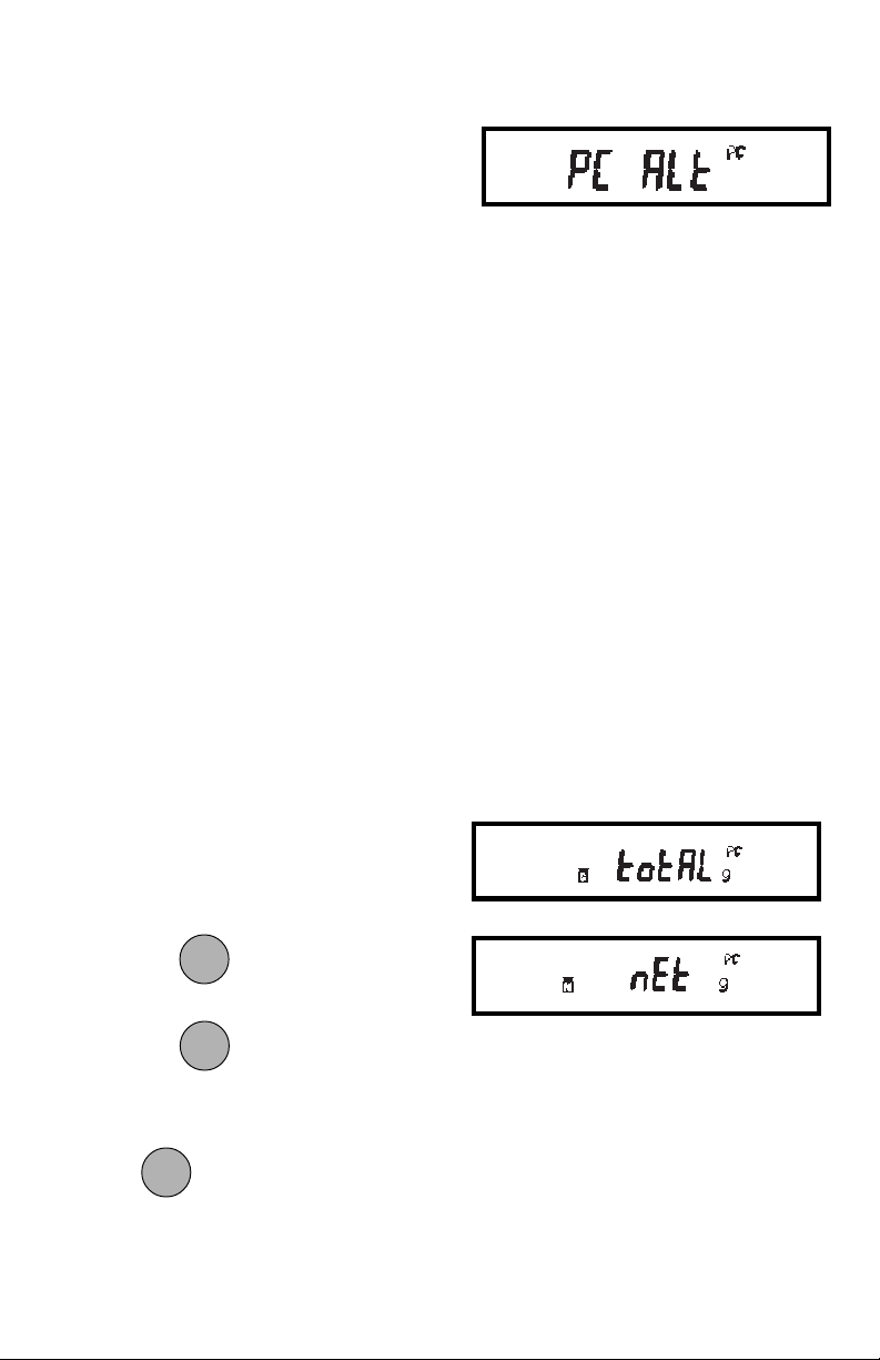
Parts Counting Alternate DisplayParts Counting Alternate Display
Parts Counting Alternate Display
Parts Counting Alternate DisplayParts Counting Alternate Display
In addition to displaying the number of
parts, the parts counting feature offers an
alternate display mode. Using the Pc Alt
submenu, you can specify the following
for the alternate display:
• An alternate unit/mode for displaying
weight or quantity of parts (can be any
unit/mode the balance offers regardless of which units are enabled in the
Unit Selection submenu).
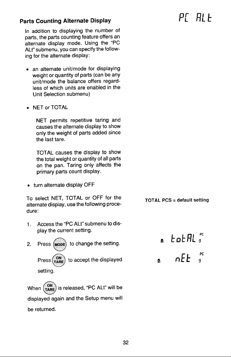
• NET or TOTAL
NET permits repetitive taring and
causes the alternate display to show
only the weight of parts added since
the last tare.
TOTAL causes the display to show
the total weight or quantity of all parts
on the pan. Taring only affects the
primary parts count display.
• Turn alternate display OFF.
To select NET, TOTAL or OFF for the
alternate display, use the following procedure:
1. Access the Pc Alt submenu to display
the current setting.
MODEMODE
MODE
2. Press
MODEMODE
to change the setting.
ONON
ON
Press to accept the displayed
ONON
TARETARE
TARE
TARETARE
setting.
ONON
ON
When
ONON
is released, PC ALT will be
TARETARE
TARE
TARETARE
displayed again and the Setup menu will
be returned.
NOTE: TOTAL PIECES = default setting.NOTE: TOTAL PIECES = default setting.
NOTE: TOTAL PIECES = default setting.
NOTE: TOTAL PIECES = default setting.NOTE: TOTAL PIECES = default setting.
Example shows alternate display set for
TOTAL grams and NET grams.
34
Page 88
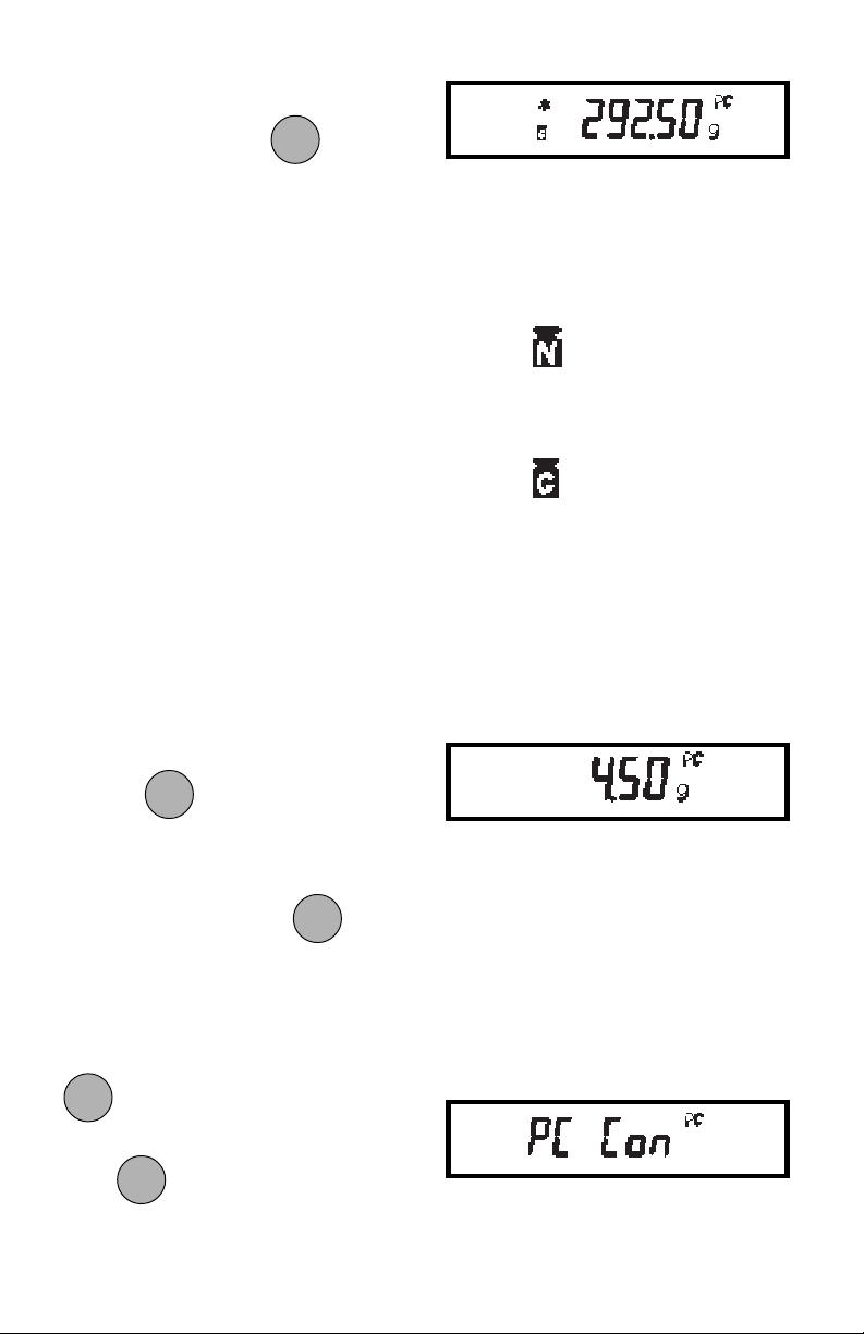
To view the weight or gross number of
MODEMODE
MODE
MODEMODE
parts on the pan, press
.
Weight is displayed in the weighing unit
selected in PC ALT in the Setup menu.
IF NETIF NET
IF NET has been selected for the alternate
IF NETIF NET
display, you may repeatedly tare the balance as needed. The alternate display will
show the net weight of parts added since
the last tare.
IF TOTALIF TOTAL
IF TOTAL has been selected for the alter-
IF TOTALIF TOTAL
nate display, total weight or quantity of
parts on the pan (relative to weight of
container already tared) will be displayed.
Taring will not affect the alternate display.
NOTES:NOTES:
NOTES: 1. The primary parts count dis-
NOTES:NOTES:
play always shows the NET
number of parts.
2. Average piece weight is not
affected by taring.
Alternate Display
Lights to indicate NET.
Lights to indicate TOTAL
or Gross.
To view the average piece weight press
PRINTPRINT
PRINT
and hold
PRINTPRINT
.
To switch between alternate display and
MODEMODE
MODE
MODEMODE
parts count display, press
.
You may change the alternate display unit
through the Setup menu without losing
the current average piece weight. To exit
or restart parts counting, press and hold
ONON
ON
ONON
until PC CON is displayed, then
TARETARE
TARE
TARETARE
release it. Return to step 2 to restart, or
MODEMODE
MODE
MODEMODE
press to change to another operating mode.
Average Piece Weight
35
Page 89
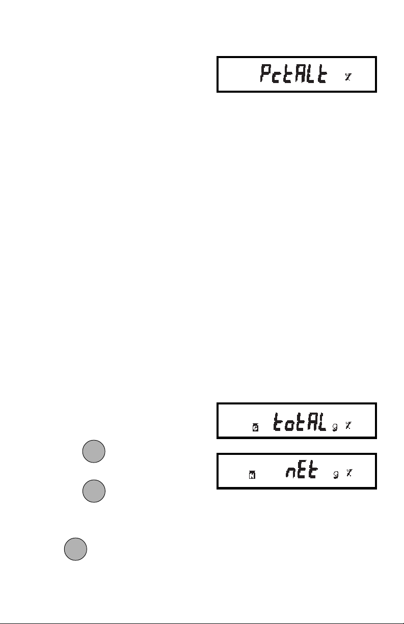
Percent Weighing Alternate DisplayPercent Weighing Alternate Display
Percent Weighing Alternate Display
Percent Weighing Alternate DisplayPercent Weighing Alternate Display
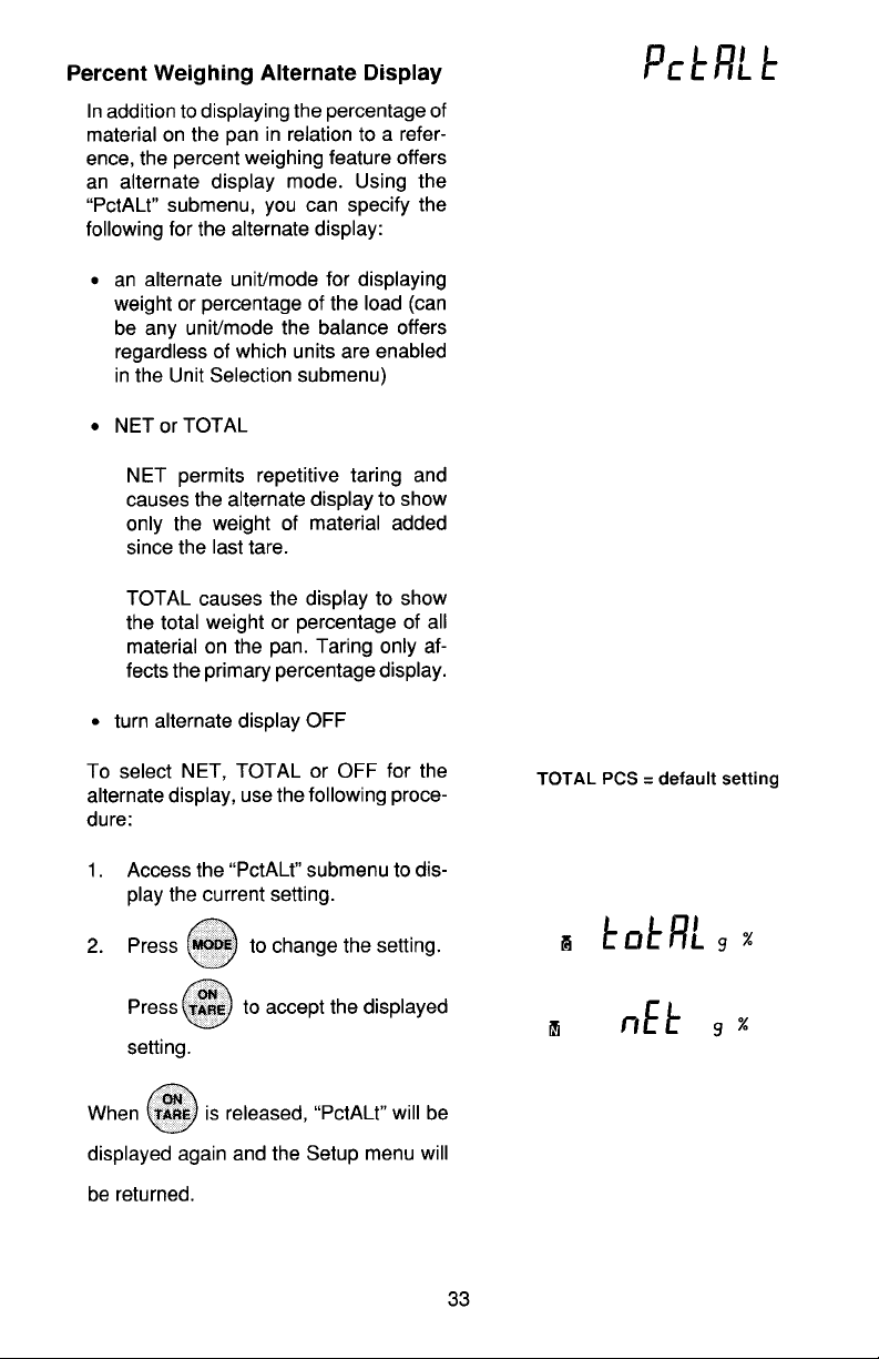
In addition to displaying the percentage of
material on the pan in relation to a reference, the percent weighing feature offers
an alternate display mode. Using the Pct
Alt submenu, you can specify the following for the alternate display:
• An alternate unit/mode for displaying
weight or percentage of the load (can
be any unit/mode the balance offers
regardless of which units are enabled
in the Unit Selection submenu).
• NET or TOTAL
NET permits repetitive taring and
causes the alternate display to show
only the weight of material added
since the last tare.
TOTAL causes the display to show
the total weight or percentage of all
material on the pan. Taring only affects the primary percentage display.
• Turn alternate display OFF.
To select NET, TOTAL or OFF for the
alternate display, use the following procedure:
1. Access the Pct Alt submenu to display the current setting.
MODEMODE
MODE
2. Press
MODEMODE
to change the setting.
ONON
ON
ONON
TARETARE
TARE
TARETARE
Press to accept the displayed
setting.
ONON
ON
ONON
When
is released, PCT ALT will be
TARETARE
TARE
TARETARE
displayed again and the Setup menu will
be returned.
NOTE: TOTAL % = default setting.NOTE: TOTAL % = default setting.
NOTE: TOTAL % = default setting.
NOTE: TOTAL % = default setting.NOTE: TOTAL % = default setting.
Example shows alternate display set for
TOTAL grams and NET grams.
36
Page 90
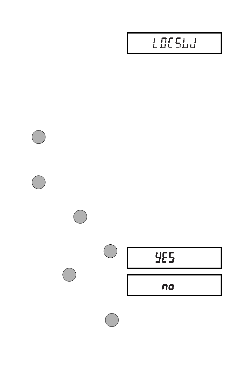
LockswitchLockswitch
Lockswitch
LockswitchLockswitch
Lockswitch enables you to lockout one or
more menu selections. Each menu can
be individually locked on or off after all
functions have been set. The Calibration,
User, Setup and Print menus can be individually locked on or off by selecting the
appropriate menu and then locked by the
switch located under the right hand side of
the control panel. Before performing the
lockout procedure, decide which functions of the balance are to be locked on or
off.
1. Access the Locksw submenu. When
ONON
ON
ONON
TARETARE
TARE
TARETARE
is released, the LOCSW
submenu is displayed.
2. To access one or more menus, press
ONON
ON
ONON
to select the calibration menu,
TARETARE
TARE
TARETARE
-CAL- is displayed.
MODEMODE
MODE
NOTE:NOTE:
NOTE: Pressing
NOTE:NOTE:
MODEMODE
changes the
selection to the other menus.
3. To select a YES or NO, press
MODEMODE
MODE
NOTE: NOTE:
NOTE: The
NOTE: NOTE:
MODEMODE
switch acts as a
toggle and can select either YES or
NO.
4. To confirm your selection, press
again. The display indicates the last
menu you were in.
MODEMODE
MODE
MODEMODE
ONON
ON
ONON
TARETARE
TARE
TARETARE
.
37
Page 91
5. To lock out the other menus, press
and repeat the procedure in
MODEMODE
MODE
MODEMODE
steps 3 and 4.
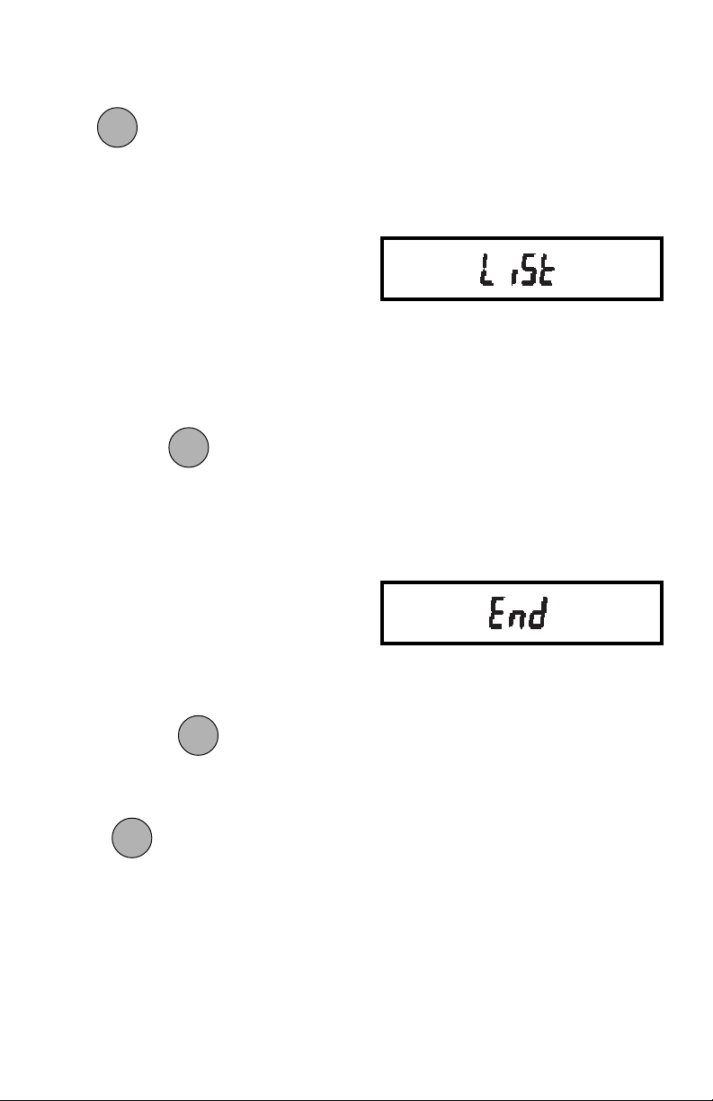
ListList
List
ListList
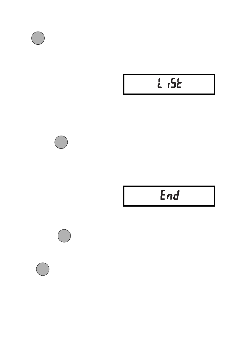
This submenu can be used to output a
listing of current menu settings via the
RS232 interface. When selected, menu
settings for the User, Setup and Print
menus will be output. To use this feature,
your balance must be connected to a
computer or printer.
To obtain a listing of current settings,
ONON
ON
ONON
simply press
when LIST is dis-
TARETARE
TARE
TARETARE
played in the Setup menu.
EndEnd
End
EndEnd
You must use End to exit the Setup menu.
Changes you make in the Setup menuChanges you make in the Setup menu
Changes you make in the Setup menu
Changes you make in the Setup menuChanges you make in the Setup menu
are only stored in memory if you useare only stored in memory if you use
are only stored in memory if you use
are only stored in memory if you useare only stored in memory if you use
End.End.
End.
End.End.
To exit the Setup menu and store your
ONON
ON
ONON
settings, press
when END is dis-
TARETARE
TARE
TARETARE
played.
ONON
ON
When
ONON
is released, the balance will
TARETARE
TARE
TARETARE
be returned to normal weighing operations.
38
Page 92
PRINT MENUPRINT MENU
PRINT MENU
PRINT MENUPRINT MENU
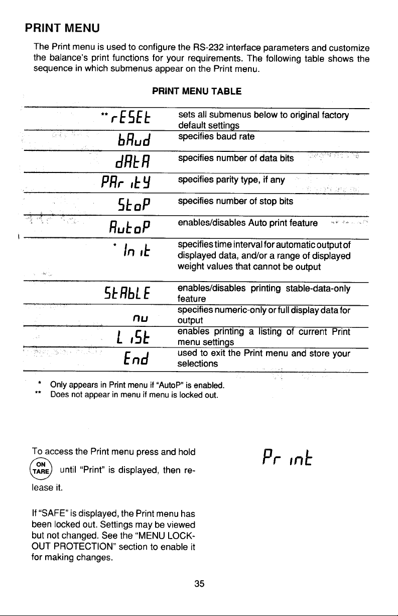
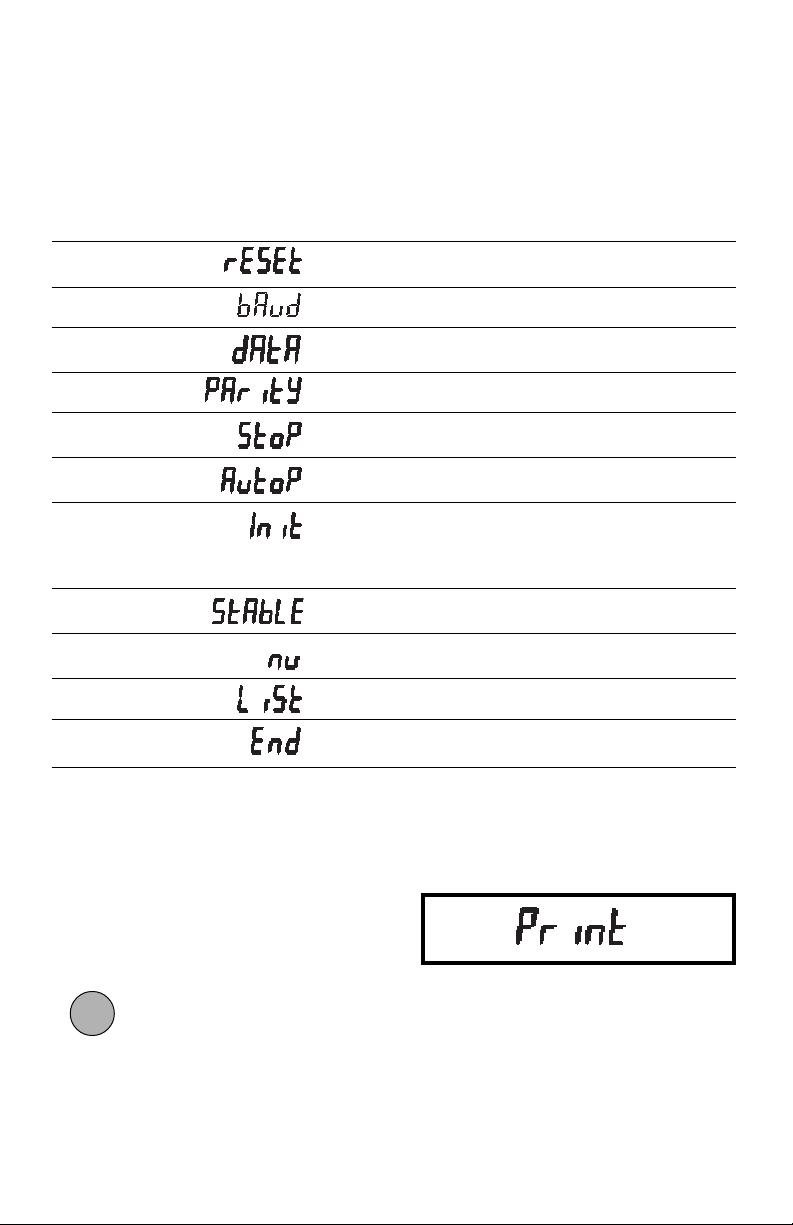
The Print menu is used to configure the RS232 interface parameters and customize
the balance’s print functions for your requirements. The following table shows the
sequence in which submenus appear on the Print menu.
PRINT MENU TABLEPRINT MENU TABLE
PRINT MENU TABLE
PRINT MENU TABLEPRINT MENU TABLE
*
Sets all submenus below to original factory
default settings.
Specifies baud rate.
Specifies number of data bits.
Specifies parity type, if any.
Specifies number of stop bits.
Enables/disables Auto print feature.
**
Specifies time interval for automatic output
of displayed data, and/or a range of displayed weight values that cannot be output.
Enables/disables printing stable-data-only
feature.
Specifies numeric-only or full display data
for output.
Enables printing a listing of current Print
menu settings.
Used to exit the Print menu and store your
selections.
* Does not appear in menu if menu is locked out.
* * Only appears in Print menu if AUTO P is enabled.
Print Menu ProtectionPrint Menu Protection
Print Menu Protection
Print Menu ProtectionPrint Menu Protection
The Print menu may be locked out to
prevent unauthorized personnel from
changing settings.
To access the Print menu press and hold
ONON
ON
ONON
until PRINT is displayed, then re-
TARETARE
TARE
TARETARE
lease it.
39
Page 93
If SAFE is displayed, the Print menu has
been locked out. Settings may be viewed
but not changed. See the Menu Lock-Out
Protection section to enable it for making
changes.
To access a submenu:
MODEMODE
MODE
1. Repeatedly press
MODEMODE
until the de-
sired submenu is displayed.
ONON
ON
2. Press to select the displayed
ONON
TARETARE
TARE
TARETARE
submenu.
NOTE:NOTE:
NOTE: You must use END to store any
NOTE:NOTE:
changes you make to the Print menu.
The following sections describe each item
on the Print menu in detail.
Reset to Factory DefaultsReset to Factory Defaults
Reset to Factory Defaults
Reset to Factory DefaultsReset to Factory Defaults
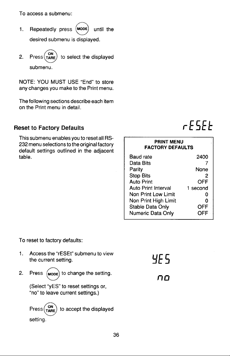
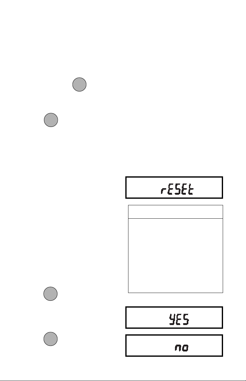
This submenu enables you to reset all
RS232 menu selections to the original
factory default settings outlined in the
adjacent table.
To reset to factory defaults:
1. Access the Reset submenu to view
the current setting.
MODEMODE
MODE
2. Press to change the setting.
MODEMODE
(Select YES to reset settings or,
no to leave current settings.)
ONON
ON
Press
ONON
to accept the displayed
TARETARE
TARE
TARETARE
setting.
PRINT MENUPRINT MENU
PRINT MENU
PRINT MENUPRINT MENU
FACTORY DEFAULTSFACTORY DEFAULTS
FACTORY DEFAULTS
FACTORY DEFAULTSFACTORY DEFAULTS
Baud rate br 2400
Data Bits 7 data
Parity None
Stop Bits 2 stop
Auto Print OFF
Auto Print Interval 1 second
Non Print Low Limit 0
Non Print High Limit 0
Stable Data Only OFF
Numeric Data Only OFF
40
Page 94
Baud RateBaud Rate
Baud Rate
Baud RateBaud Rate
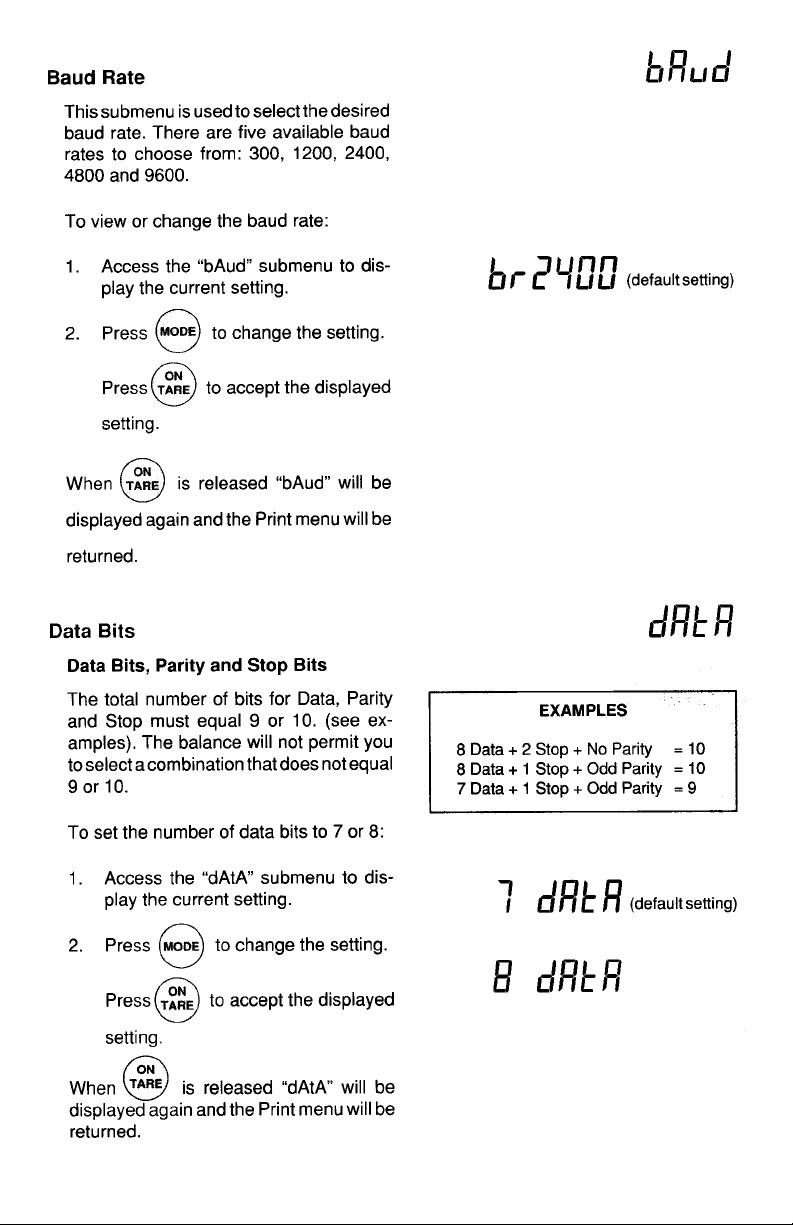
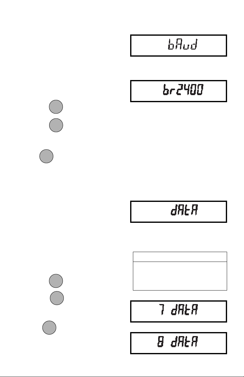
This submenu is used to select the desired baud rate. There are five available
baud rates to choose from: 300, 1200,
2400, 4800 and 9600.
To view or change the baud rate:
1. Access the Baud submenu to display
the current setting.
MODEMODE
MODE
Press
MODEMODE
to change the setting.
ONON
ON
ONON
TARETARE
TARE
TARETARE
to accept the displayed
2. Press
setting.
ONON
ON
When
ONON
is released, BAUD will be
TARETARE
TARE
TARETARE
displayed again and the Print menu will be
returned.
Data BitsData Bits
Data Bits
Data BitsData Bits
The total number of bits for Data, Parity
and Stop must equal 9 or 10. (see examples). The balance will not permit you
to select a combination that does not equal
9 or 10.
To set the number of data bits to 7 or 8:
1. Access the Data submenu to display
the current setting.
2. Press
Press
to change the setting.
MODEMODE
MODE
MODEMODE
ONON
ON
ONON
to accept the displayed
TARETARE
TARE
TARETARE
setting.
ONON
ON
When
ONON
is released, DATA will be
TARETARE
TARE
TARETARE
displayed again and the Print menu will be
returned.
41
EXAMPLESEXAMPLES
EXAMPLES
EXAMPLESEXAMPLES
8 Data + 2 Stop + No Parity = 10
8 Data + 1 Stop + Odd Parity = 10
7 Data + 1 Stop + Odd Parity = 9
Page 95
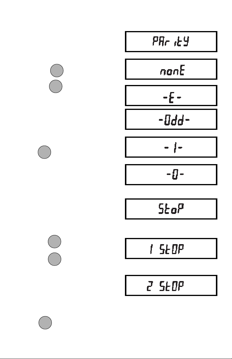
ParityParity
Parity
ParityParity
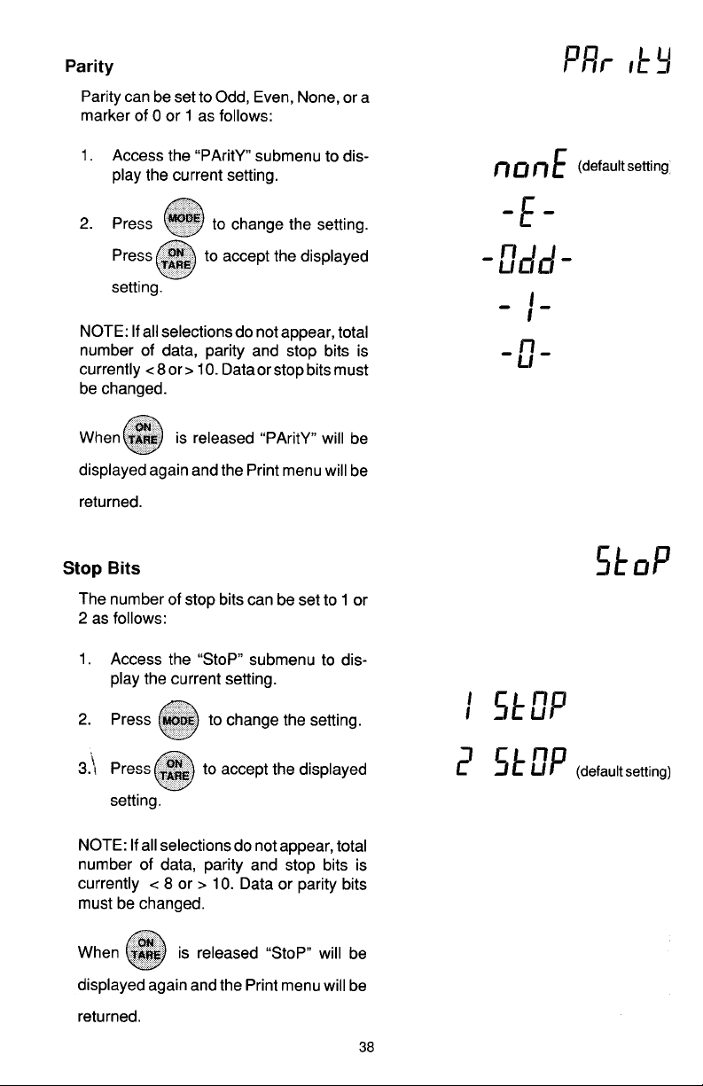
Parity can be set to Odd, Even, None, or
a marker of 0 or 1 as follows:
1. Access the Parity submenu to display the current setting.
2. Press
Press to accept the displayed
to change the setting.
MODEMODE
MODE
MODEMODE
ONON
ON
ONON
TARETARE
TARE
TARETARE
setting.
NOTE: NOTE:
NOTE: If all selections do not appear, total
NOTE: NOTE:
number of data, parity and stop bits is
currently < 8 or > 10, data or stop bits must
be changed.
ONON
ON
When
ONON
is released, PARITY will be
TARETARE
TARE
TARETARE
displayed again and the Print menu will be
returned.
Stop BitsStop Bits
Stop Bits
Stop BitsStop Bits
The number of stop bits can be set to 1 or
2 as follows:
1. Access the Stop submenu to display
the current setting.
MODEMODE
MODE
2. Press to change the setting.
3. Press
MODEMODE
ONON
ON
ONON
to accept the displayed
TARETARE
TARE
TARETARE
setting.
NOTE: NOTE:
NOTE: If all selections do not appear, total
NOTE: NOTE:
number of data, parity and stop bits is
currently < 8 or > 10, data or parity bits
must be changed.
ONON
ON
When
ONON
is released, STOP will be
TARETARE
TARE
TARETARE
displayed again and the Print menu will be
returned.
42
Page 96
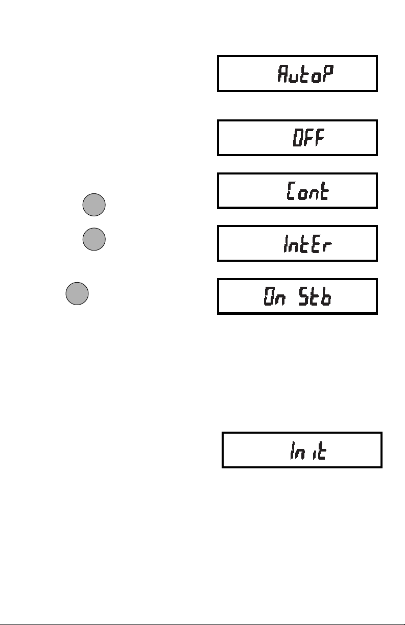
Auto Print FeatureAuto Print Feature
Auto Print Feature
Auto Print FeatureAuto Print Feature
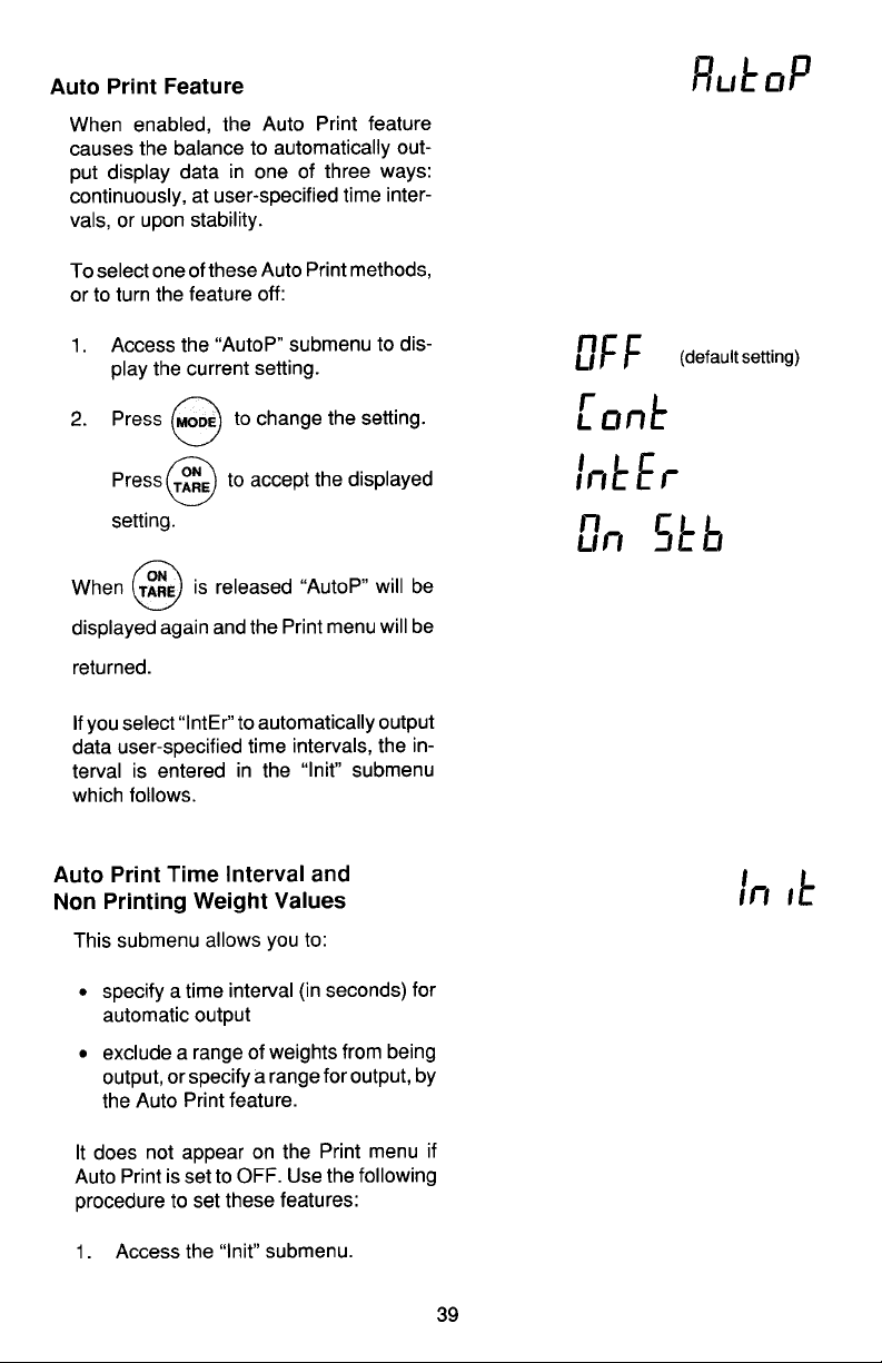
When enabled, the Auto Print feature
causes the balance to automatically output display data in one of three ways:
continuously, at user specified time intervals, or upon stability.
To select one of these Auto Print methods, or to turn the feature off:
1. Access the Auto P submenu to display the current setting.
MODEMODE
MODE
Press
MODEMODE
to change the setting.
ONON
ON
ONON
to accept the displayed
TARETARE
TARE
TARETARE
2. Press
setting.
ONON
ON
When is released, Auto P will be
ONON
TARETARE
TARE
TARETARE
displayed again and the Print menu will be
returned.
If you select INTER to automatically output data user specified time intervals, the
interval is entered in the Init submenu
which follows.
Auto Print Time Interval andAuto Print Time Interval and
Auto Print Time Interval and
Auto Print Time Interval andAuto Print Time Interval and Non Printing Weight ValuesNon Printing Weight Values
Non Printing Weight Values
Non Printing Weight ValuesNon Printing Weight Values
This submenu allows you to:
• Specify a time interval (in seconds) for
automatic output.
• Exclude a range of weights from being
output, or specify a range for output, by
the Auto Print feature.
It does not appear on the Print menu if
Auto Print is set to OFF. Use the following
procedure to set these features:
1. Access the Init submenu.
43
Page 97
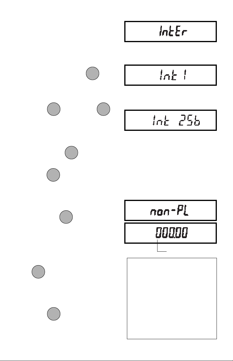
2. If Inter was selected in the Auto Print
submenu, INTER will be displayed
and you may continue with step 3. If
it was not selected, NON-PL will be
displayed. Proceed to step 7.
3. To enter a time interval for automatic
ONON
ON
data output, press when
ONON
TARE TARE
TARE
TARE TARE
INTER is displayed. The current interval (in seconds) will be displayed.
PRINTPRINT
PRINT
4. Press
MODEMODE
MODE
MODEMODE
to increase or to
PRINTPRINT
decrease the number.
5. When the desired number is dis-
ONON
ON
played, press to accept it.
MODEMODE
MODE
6. Press once to proceed to step
MODEMODE
ONON
TARETARE
TARE
TARETARE
7, or three times to display END and
proceed to step 15.
Set time interval from
1 to 256 seconds.
7. To enter a range of non printing val-
ONON
ON
ues, press
ONON
when NON-PL is
TARETARE
TARE
TARETARE
displayed. The current value for the
low end of the range will be displayed
with the first digit flashing.
8. To change the number, start with the
first digit (flashing). Repeatedly press
MODEMODE
MODE
MODEMODE
to change the value to any
number from -9 to +9. A minus sign
will light to indicate a negative value.
9. When the desired value is displayed,
ONON
ON
press
ONON
to accept it and the next
TARETARE
TARE
TARETARE
digit will begin flashing.
FLASHING
To exclude dataTo exclude data
To exclude data
To exclude dataTo exclude data
WITHIN SELECTED RANGE:WITHIN SELECTED RANGE:
WITHIN SELECTED RANGE:
WITHIN SELECTED RANGE:WITHIN SELECTED RANGE:
SET non-PL < non-PH
Example:non-PL=7g, non-PH=11g
Values <7
To exclude dataTo exclude data
To exclude data
To exclude dataTo exclude data
OUTSIDE SELECTED RANGE:OUTSIDE SELECTED RANGE:
OUTSIDE SELECTED RANGE:
OUTSIDE SELECTED RANGE:OUTSIDE SELECTED RANGE:
OR OR
OR >11 will be output.
OR OR
Set non-PL > non-PH
Example:non-PL=11g, non-PH=7g
Values >7
AND AND
AND <11 will be output.
AND AND
44
Page 98
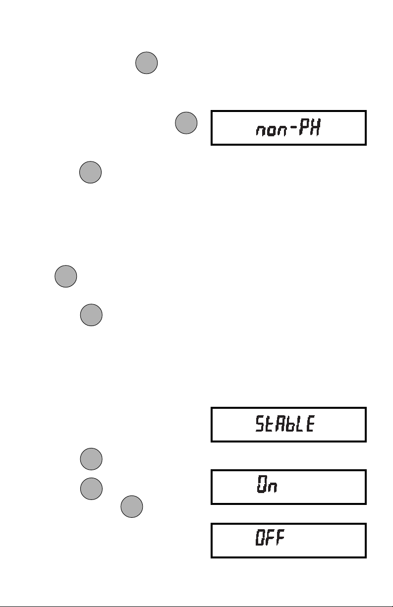
10. Set all digits in the same manner. If an
PRINTPRINT
PRINT
error is made, press
PRINTPRINT
to backup
to the desired digit and change it.
11. After the last digit is entered, NON-PL
MODEMODE
MODE
will be displayed again. Press
MODEMODE
to proceed to NON-PH, the high limit.
ONON
ON
12. Press
ONON
to view the current value
TARETARE
TARE
TARETARE
for the high end of the range.
13. Change the number as needed using
the same procedure as in step 8.
14. After the last digit is entered, NONPH will be displayed again. Press
MODEMODE
MODE
MODEMODE
to display End.
ONON
ON
15. Press
ONON
when END is displayed
TARETARE
TARE
TARETARE
to return to the Print menu.
Print Stable Data OnlyPrint Stable Data Only
Print Stable Data Only
Print Stable Data OnlyPrint Stable Data Only
When enabled, this feature permits only
stable display data to be output. To set the
feature ON or OFF:
1. Access the Stable submenu to display the current status.
MODEMODE
MODE
2. Press
MODEMODE
to change the status.
ONON
ON
Press
status. When is released,
ONON
to accept the displayed
TARETARE
TARE
TARETARE
ONON
ON
ONON
TARETARE
TARE
TARETARE
STABLE will be displayed again and
the Print menu will be returned.
45
Page 99
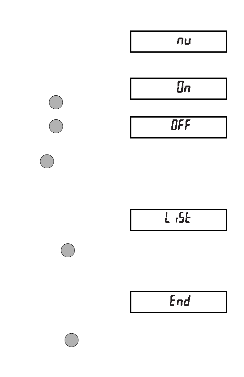
Print Numeric Data OnlyPrint Numeric Data Only
Print Numeric Data Only
Print Numeric Data OnlyPrint Numeric Data Only
This submenu is used to select numeric
data only, or full display data for RS232
output. Set this feature ON to output numeric display data only, or OFF to output
full display data as follows:
1. Access the Nu submenu to display
the current status.
MODEMODE
MODE
2. Press
3. Press
MODEMODE
to change the status.
ONON
ON
ONON
to accept the displayed
TARETARE
TARE
TARETARE
status.
ONON
ON
When
ONON
is released, NU will be dis-
TARETARE
TARE
TARETARE
played again and the Print menu will be
returned.
ListList
List
ListList
This submenu can be used to output a
listing of current menu settings via the
RS232 interface. When selected, menu
settings for both the Setup and Print menus
will be output. To obtain a listing of current
ONON
ON
settings, press when LIST is dis-
ONON
TARETARE
TARE
TARETARE
played.
EndEnd
End
EndEnd
You must use End to exit the Print menu.
Changes you make in the Print menuChanges you make in the Print menu
Changes you make in the Print menu
Changes you make in the Print menuChanges you make in the Print menu
are only stored in memory if you useare only stored in memory if you use
are only stored in memory if you use
are only stored in memory if you useare only stored in memory if you use
EndEnd
End
EndEnd
To exit the Print menu and store your
ONON
ON
selections, press
ONON
when END is dis-
TARETARE
TARE
TARETARE
played. The balance will be returned to
normal weighing operations.
46
Page 100
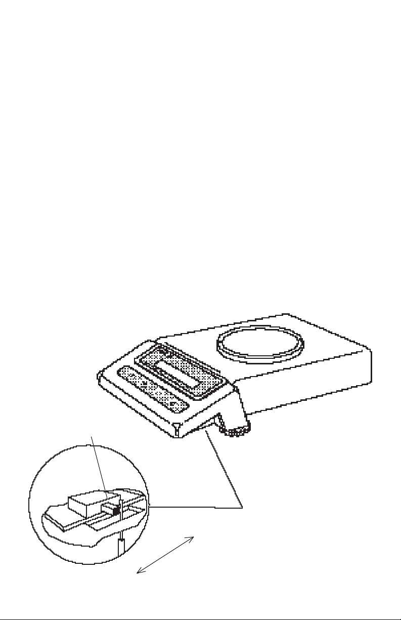
MENU LOCK-OUT PROTECTIONMENU LOCK-OUT PROTECTION
MENU LOCK-OUT PROTECTION
MENU LOCK-OUT PROTECTIONMENU LOCK-OUT PROTECTION
Access to the Calibration, User, Setup
and Print menus, can be disabled using
the lock out switch located under the right
side of the balance, near the display.
1. Turn the display off and unplug the
power cord.
2. Slide the balance toward you, with
the front over the edge of a table.
(You can also turn the balance on its
left side, but if you do, you MUST
remove the pan and spill ring first!)
3. Locate hole under display where
switch is located.
4. Using a small screwdriver, slide the
switch forward for LOCKED or back
for UNLOCKED.
5. Plug in the power cord and turn on the
balance.
LOCK OUT
SWITCH
LOCK
UNLOCK
47
 Loading...