

Page 1
Pioneer
PX Series Balances
Instruction Manual
Page 2

Page 3

PX Series Balance EN-1
Table of Contents
1. INTRODUCTION .............................................................................................................. EN-3
1.1 Description ............................................................................................................................................. EN-3
1.2 Features ................................................................................................................................................. EN-3
1.3 Definition of Signal Warnings and Symbols ........................................................................................... EN-3
1.4 Safety Precautions ................................................................................................................................. EN-3
2. INSTALLATION ............................................................................................................... EN-4
2.1 Unpacking .............................................................................................................................................. EN-4
2.2 Select the Location ................................................................................................................................ EN-4
2.3 Leveling .................................................................................................................................................. EN-4
2.4 Connecting Power and Acclimating the Balance ................................................................................... EN-5
2.5 Connecting the Interface ........................................................................................................................ EN-5
2.6 Initial Calibration .................................................................................................................................... EN-5
3. OPERATION .................................................................................................................... EN-6
3.1 Overview of Display, Home Screen ....................................................................................................... EN-6
3.2 Principal Functions and Main Menu ....................................................................................................... EN-7
3.3 Overview of Parts and Features – Draft Shield Models ......................................................................... EN-7
3.4 Overview of Parts and Features – Non-Draft Shield Models ................................................................. EN-7
4. APPLICATIONS ............................................................................................................... EN-8
4.1 Weighing ................................................................................................................................................ EN-8
4.2 Parts Counting ....................................................................................................................................... EN-8
4.3 Percent Weighing ................................................................................................................................. EN-10
4.4 Dynamic Weighing ............................................................................................................................... EN-11
4.5 Density Determination .......................................................................................................................... EN-12
4.5.1 Measuring the Density of a Sinking Solid Using Water ................................................................... EN-17
4.5.2 Measuring the Density of a floating Solid Using Water.................................................................... EN-18
4.5.3 Measuring the Density of a Solid Using an Auxiliary Liquid other than Water ................................ EN-18
4.5.4 Measuring the Density of a Liquid Using a Calibrated Sinker ......................................................... EN-19
4.5.5 Measuring the Density of Porous Material Using Oil ....................................................................... EN-21
4.6 Additional Features .............................................................................................................................. EN-23
5. MENU SETTINGS .......................................................................................................... EN-24
5.1 Menu Navigation .................................................................................................................................. EN-24
5.1.1 Changing Settings ............................................................................................................................ EN-24
5.2 Calibration ............................................................................................................................................ EN-24
5.2.1 Calibration Sub-menu (InCal models) .............................................................................................. EN-24
5.2.2 Internal Calibration (not applicable to ExCal models) ...................................................................... EN-25
5.2.3 InCal Adjust (not applicable to ExCal models) ................................................................................. EN-25
5.2.4 Span Calibration............................................................................................................................... EN-25
5.2.5 Linearity Calibration ......................................................................................................................... EN-26
5.3 Balance Setup ...................................................................................................................................... EN-28
5.3.1 Language ......................................................................................................................................... EN-28
5.3.2 Filter Level ........................................................................................................................................ EN-28
5.3.3 AZT (Auto Zero Tracking) ................................................................................................................ EN-28
5.3.4 Auto Tare ......................................................................................................................................... EN-28
5.3.5 Graduations ...................................................................................................................................... EN-29
5.3.6 Date Format ..................................................................................................................................... EN-29
5.3.7 Date Setup ....................................................................................................................................... EN-29
5.3.8 Time Format ..................................................................................................................................... EN-29
5.3.9 Time Setup ....................................................................................................................................... EN-29
5.3.10 Brightness ........................................................................................................................................ EN-29
5.3.11 Auto Dim .......................................................................................................................................... EN-29
5.3.12 Capacity Bar ..................................................................................................................................... EN-29
5.3.13 Approved Mode ................................................................................................................................ EN-30
5.4 Weighing Units ..................................................................................................................................... EN-30
5.5 RS232 Interface Setup ......................................................................................................................... EN-32
5.5.1 Baud Rate ........................................................................................................................................ EN-32
5.5.2 Transmission .................................................................................................................................... EN-32
Page 4

EN-2 PX Series Balance
5.5.3 Handshake ....................................................................................................................................... EN-33
5.6 Print Settings ........................................................................................................................................ EN-33
5.6.1 Stable Only ....................................................................................................................................... EN-33
5.6.2 Numeric Only ................................................................................................................................... EN-33
5.6.3 Single Header .................................................................................................................................. EN-33
5.6.4 Print To ............................................................................................................................................. EN-33
5.6.5 Auto Print ......................................................................................................................................... EN-33
5.6.6 Header ............................................................................................................................................. EN-33
5.6.7 Date and Time.................................................................................................................................. EN-33
5.6.8 Balance ID ........................................................................................................................................ EN-34
5.6.9 Balance Name.................................................................................................................................. EN-34
5.6.10 User Name ....................................................................................................................................... EN-34
5.6.11 Project Name ................................................................................................................................... EN-34
5.6.12 Application Name ............................................................................................................................. EN-34
5.6.13 Result ............................................................................................................................................... EN-34
5.6.14 Gross. ............................................................................................................................................... EN-34
5.6.15 Net..... ............................................................................................................................................... EN-34
5.6.16 Tare... ............................................................................................................................................... EN-34
5.6.17 Line Feed ......................................................................................................................................... EN-34
5.7 GLP ...................................................................................................................................................... EN-35
5.7.1 Header ............................................................................................................................................. EN-35
5.7.2 Balance Name.................................................................................................................................. EN-35
5.7.3 User Name ....................................................................................................................................... EN-35
5.7.4 Project Name ................................................................................................................................... EN-35
5.8 Factory Reset ....................................................................................................................................... EN-35
5.9 Lockout................................................................................................................................................. EN-35
6. LEGAL FOR TRADE (LFT) ........................................................................................... EN-36
6.1 Settings ................................................................................................................................................ EN-36
6.2 Verification ........................................................................................................................................... EN-36
6.3 Securing the Menu ............................................................................................................................... EN-36
6.4 Sealing Access to the Balance Settings .............................................................................................. EN-36
7. Printing .......................................................................................................................... EN-37
7.1 Connecting, Configuring and Testing the Printer / Computer Interface ............................................... EN-37
7.2 Output Format ...................................................................................................................................... EN-38
7.3 Printout Examples ................................................................................................................................ EN-38
8. MAINTENANCE ............................................................................................................. EN-40
8.1 Calibration ............................................................................................................................................ EN-40
8.2 Cleaning ............................................................................................................................................... EN-40
8.3 Troubleshooting ................................................................................................................................... EN-40
8.4 Service Information .............................................................................................................................. EN-40
9. TECHNICAL DATA ........................................................................................................ EN-41
9.1 Specifications ....................................................................................................................................... EN-41
9.2 Drawings and Dimensions ................................................................................................................... EN-46
9.3 Accessories .......................................................................................................................................... EN-46
9.4 Communication .................................................................................................................................... EN-47
9.4.1 Interface Commands ........................................................................................................................ EN-47
9.4.2 RS232 (DB9) Pin Connections ........................................................................................................ EN-48
9.4.3 USB Interface ................................................................................................................................... EN-48
9.4.4 USB Connection............................................................................................................................... EN-49
10. SOFTWARE UPDATES ................................................................................................. EN-49
11. COMPLIANCE ............................................................................................................... EN-50
Page 5
PX Series Balance EN-3
Operation Controls: 2-line backlit display, with 6
weighing applications and many other features.
WARNING
For a hazardous situation with medium risk, possibly resulting in injuries or
death if not avoided.
CAUTION
For a hazardous situation with low risk, resulting in damage to the device or
the property or in loss of data, or injuries if not avoided.
Attention
For important information about the product
Note
For useful information about the product
CAUTION: Read all safety warnings before installing, making connections, or servicing this equipment.
Failure to comply with these warnings could result in personal injury and/or property damage. Retain all
instructions for future reference.
Direct Current
Alternating Current
1. INTRODUCTION
1.1 Description
The PX balance is a precision weighing instrument that will provide you with years of service if properly cared for.
PX balances are available in capacities from 82 grams to 8200 grams.
1.2 Features
1.3 Definition of Signal Warnings and Symbols
Safety notes are marked with signal words and warning symbols. These show safety issues and warnings. Ignoring
the safety notes may lead to personal injury, damage to the instrument, malfunctions and false results.
Warning Symbols
General Hazard Electrical Shock Hazard
1.4 Safety Precautions
Verify that the AC adapter’s input voltage range and plug type are compatible with the local AC main power
supply.
Make sure that the power cord does not pose a potential obstacle or tripping hazard.
Do not position the balance such that it is difficult to reach the power connection.
The balance is for indoor use only. Do not operate the equipment in hazardous or unstable environments.
Operate the equipment only under ambient conditions specified in these instructions.
Do not drop loads on the pan.
Use the balance only in dry locations.
Disconnect the equipment from the power supply when cleaning.
Use only approved accessories and peripherals.
Service should only be performed by authorized personnel.
Page 6
EN-4 PX Series Balance
2. INSTALLATION
2.1 Unpacking
Carefully remove your PX balance and each of its components from the package. The included components vary
depending on the balance model (see the list below). Save the packaging to ensure safe storage and transport.
Please read the manual completely before installing and using the PX balance to avoid incorrect operation.
Components included:
Balance
Power adapter + Attaching plug
Stainless steel pan
Pan support (for 0.1 g / 0.01 g model only)
Warrenty card
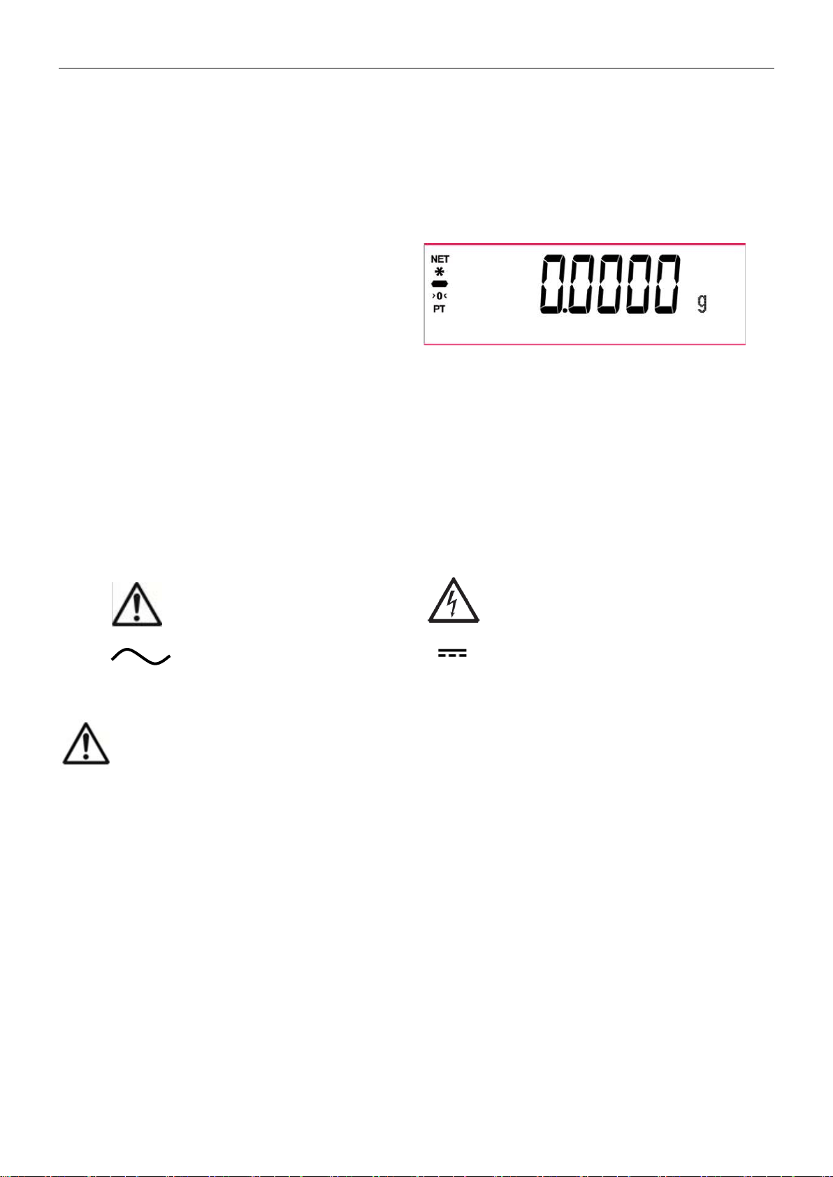
2.2 Select the Location
Avoid heat sources, rapid temperature changes, air current or excessive vibrations. Allow sufficient space.
2.3 Leveling
Be sure the balance is level before it is used or after its location is changed.
The PX balance has a level bubble in a small round window beside the display.
To level the balance, adjust the 4 Leveling Feet until the bubble is centered in the circle.
Please refer to Figure 2-1 for leveling.
Figure 2-1. Leveling
Page 7
PX Series Balance EN-5
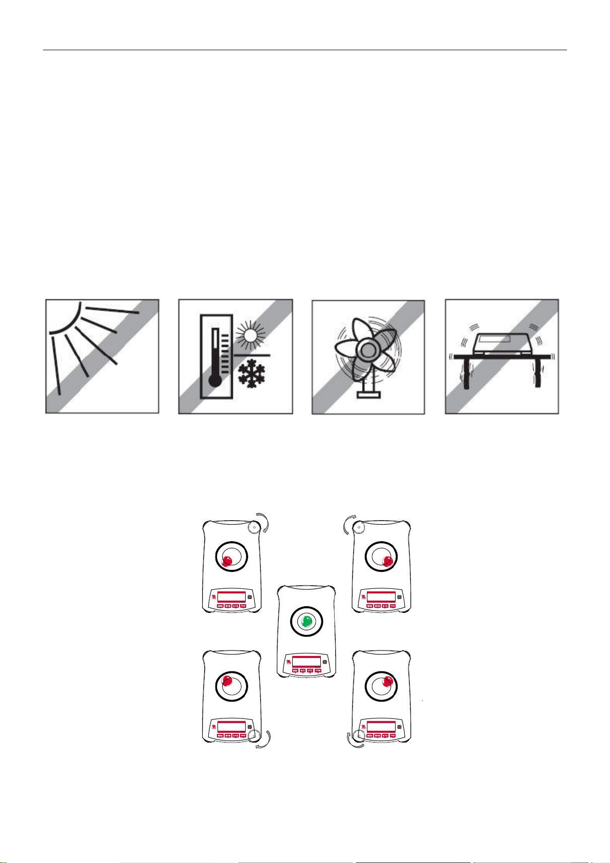
The PX balance has two data interfaces, RS232 and USB.
Use the RS-232 port to connect either to a computer or a printer with a standard (straight-through) serial cable.
Use the USB port to connect to a computer with a USB 2.0 Type A to Type B cable.
Interface connections on the rear of the balance
USB:Used to connect to PC only
RS232:Used to connect to PC or Printer
Note: For Connecting, Configuring and Testing the Printer / Computer Interface, see the Printing section.
USB
RS232
2.4 Connecting Power and Acclimating the Balance
Connect the DC output connector to the power receptacle on the rear of the balance. Then connect the AC adapter
plug to a suitable electrical outlet.
Acclimating
It is suggested that the balance should not be used until it has been connected to power and acclimated to the
environment for a certain period of time. In the case of balance with the precision above 0.1 mg, the acclimation
time should be 1.5 hours; in the case of balance with the precision of 0.01 mg, the acclimation time should be more
than 4 hours.
2.5 Connecting the Interface
2.6 Initial Calibration
When the PX balance is first installed, or when it is moved to another location, it must be calibrated to ensure
accurate weighing results. PX balances are classified into two categories, InCal models and ExCal models. InCal
models have a built-in calibration mechanism which can calibrate the balance automatically and does not require
the use of external calibration masses. If preferred, InCal models can also be manually calibrated with external
masses. ExCal models are calibrated with external masses. Make sure to have the appropriate calibration masses
available before beginning calibration.
Page 8
EN-6 PX Series Balance
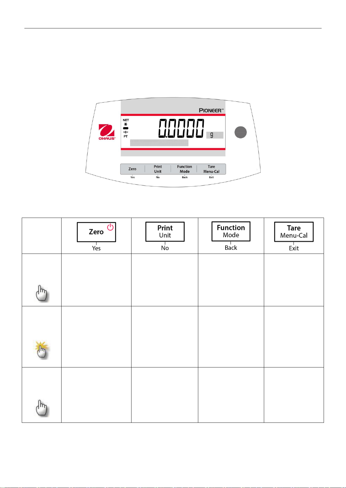
CONTROLS
Button
Primary
Function
(Short
Press)
On / Zero
If the Indicator is
Off, turns on the
Indicator.
If Indicator is On,
sets zero.
Print
Sends the current
displayed value to
the serial interface.
Function
Operation is
dependent on the
application mode.
Tare
Performs tare
operation.
Secondary
Function
(Press and
Hold)
Off
Zeroing current
value.
Unit
Changes weighing
units.
Mode
Changes
application mode.
Menu-Cal
Enters the main
menu.
Calibration is
the first submenu.
Views the preset
Tare value.
Menu
Function
(Short
Press)
Yes
Accepts the current
(blinking) setting on
the display.
No
Rejects the current
(blinking) setting
on the display.
Increments a value
being entered.
Back
Reverts back to
previous menu
item.
Decrements a
value being
entered.
Exit
Immediately
exits the submenu.
Aborts a
calibration in
progress.
3. OPERATION
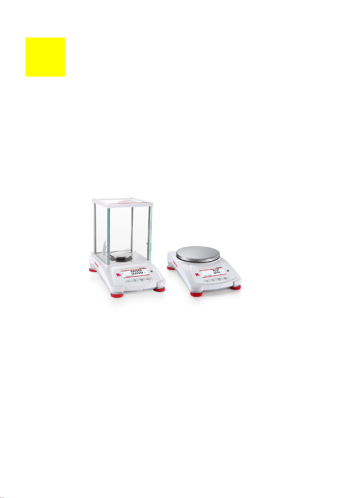
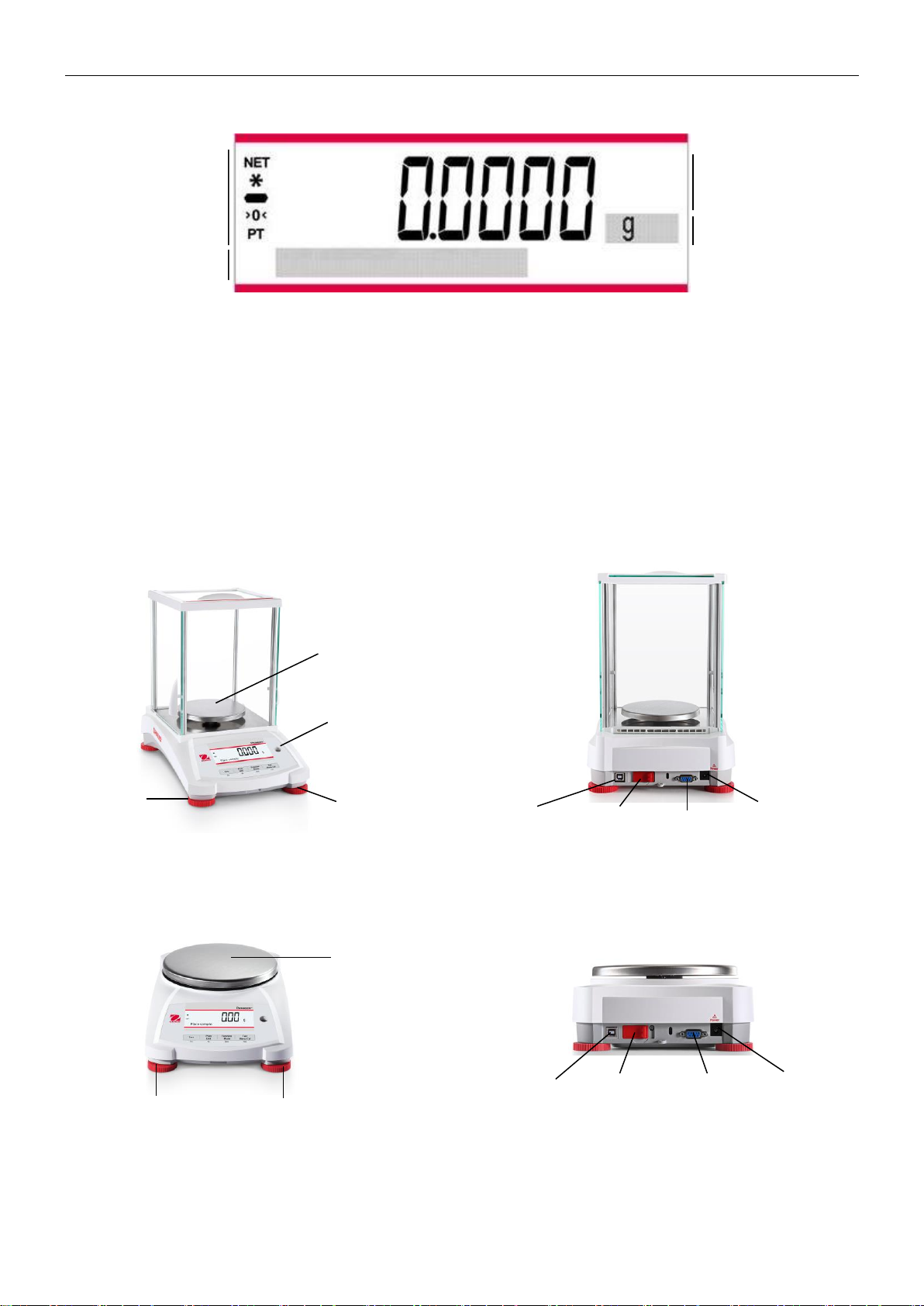
3.1 Overview of Display, Home Screen
The PX balance has a 2-line backlit display.
CONTROL FUNCTIONS
Page 9
PX Series Balance EN-7
Weighing:
Press Zero to set the display to zero. Place an object on the pan. The display indicates the gross
weight.
Taring:
With no load on the pan, press Zero to set the display to zero. Place an empty container on the
pan and press Tare. Add material to the container and its net weight is displayed. After the
container and the objects are removed, the load will be displayed as a negative number. Press
Tare to clear.
Zero:
Press Zero to zero the balance.
Dot-matrix
Display:
The relevant data in the specific application mode are shown in the dot-matrix display area.
Result Field:
Information varies
by application
Unit
Instructional Messages
Net (NET)
Stability (*)
Negative (-)
Centre of Zero (>0<)
Pre-tare (PT)
Pan
Level Indicator
Adjustable
Foot
Adjustable
Foot
USB
Device
Security Switch
RS232
Power Input
Pan
Adjustable Foot
Adjustable Foot
USB
Device
Security Switch
RS232
Power Input
MAIN APPLICATION SCREEN
3.2 Principal Functions and Main Menu
3.3 Overview of Parts and Features – Draft Shield Models
3.4 Overview of Parts and Features – Non-Draft Shield Models
Page 10
EN-8 PX Series Balance
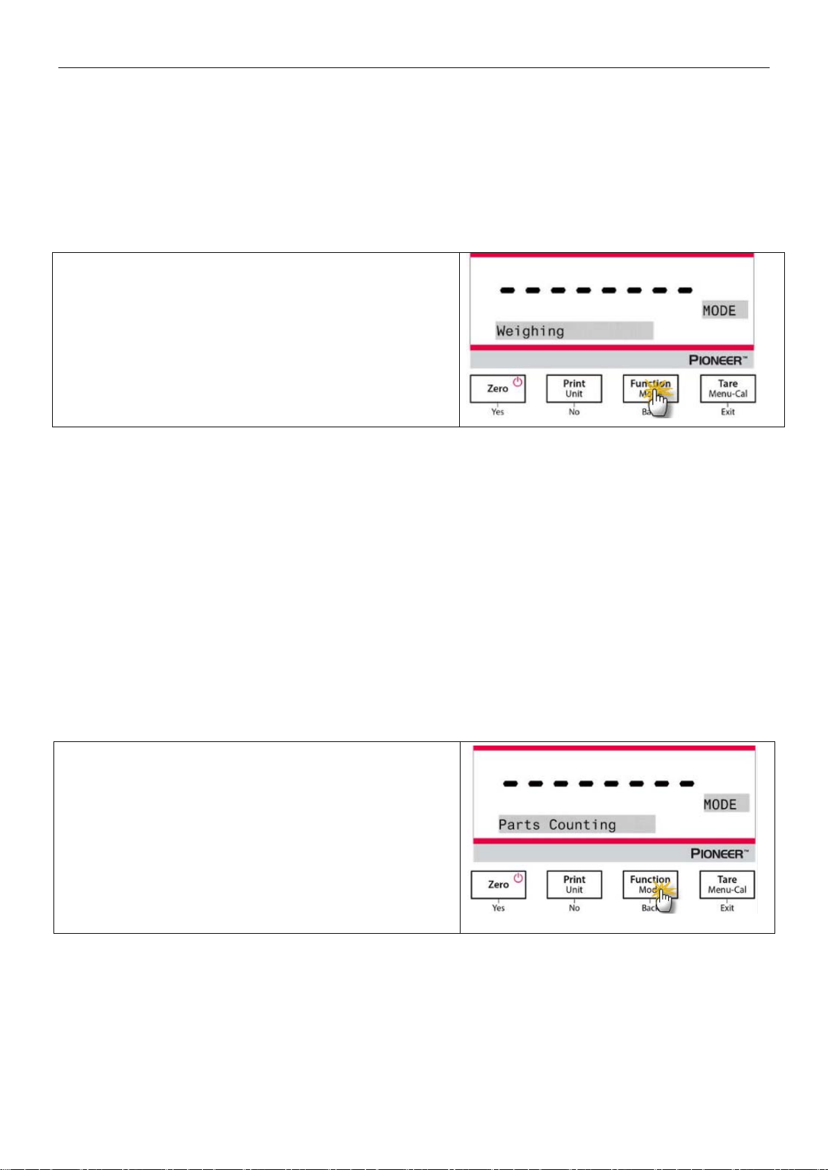
1. Press Tare or Zero if necessary to begin.
2. Press and hold the Function / Mode button to select
Weighing (this application is the default).
3. Place objects on the pan to display the weight. Once
the reading is stable, the * will appear.
4. The resulting value is displayed in the active unit of
measure.
To view or adjust the current settings.
1. Press Tare or Zero if necessary to begin.
2. Press and hold the Function / Mode button until
Parts Counting appears.
4. APPLICATIONS
The PX balance can be operated in 6 application modes by long pressing the Function / Mode button.
4.1 Weighing
Note: Before using any application, be sure the balance has been leveled and calibrated.
Use this application to determine the weight of objects in the selected unit of measure.
Weighing
Item Settings
• Capacity Bar: When set to On, the capacity bar is displayed in the reference field. The capacity will not
display when the balance is set to zero.
• Weighing Units: Change the displayed unit. See Section 5.4 for more information.
• Filter Level: Change Filtering level. See Section 5.3.2 for more information.
• GLP Data: See Section 5.7 for more information.
• Print Settings: Change printing settings. See Section 7 for more information.
4.2 Parts Counting
Note: Before using any application, be sure the balance has been leveled and calibrated. The minimum piece
weight should be no less than 0.1d.
Use this application to count samples of uniform weight.
Parts Counting
Page 11
PX Series Balance EN-9
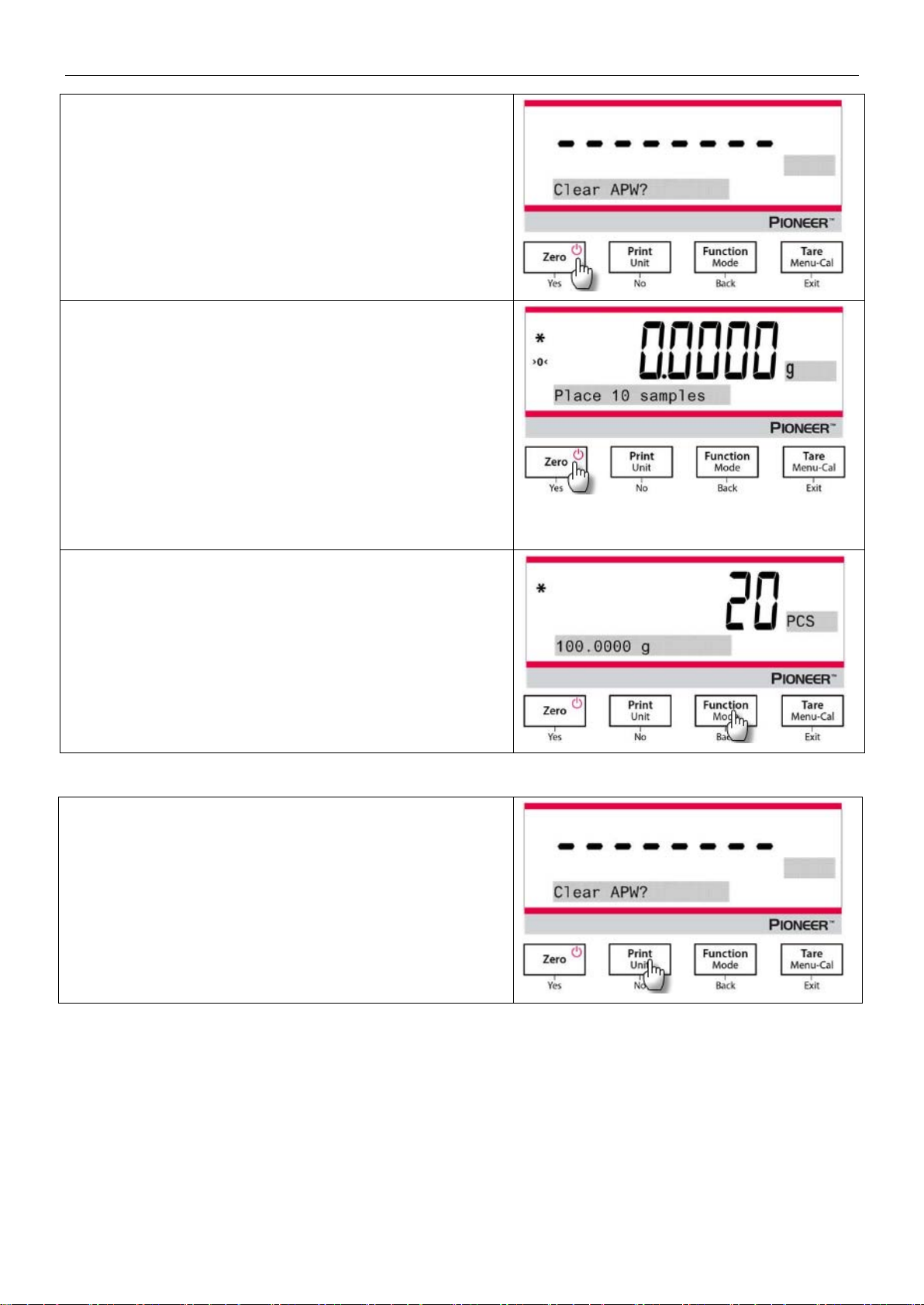
3. After confirmation by pressing Yes, the message
"Clear APW?" will appear on the screen.
4. If the APW of the last Parts Counting operation needs
to be kept, press No when the message "Clear
APW?" displays.
5. Press Yes, and the message "Sample size 10" will
display with the numeral "10" (default) flashing.
6. Confirm the sample size by pressing Yes, and place
10 samples on the pan to display the weight. Press
No or Back to increase or decrease the value as
desired.
7. Press the Function / Mode button so that the weight
of the 10 samples is used to establish the average
piece weight (APW). The display will show 10 pieces.
8. To view the piece weight or the total weight, press the
Function / Mode button.
9. Place additional objects on the pan, and the
corresponding number of pieces will display.
Sample: The sample size ranges from 1 to 1000. The default
value is 10.
Note: To ensure accurate counting, the minimum piece
weight should be no less than 0.1d.
Item Settings
Page 12
EN-10 PX Series Balance
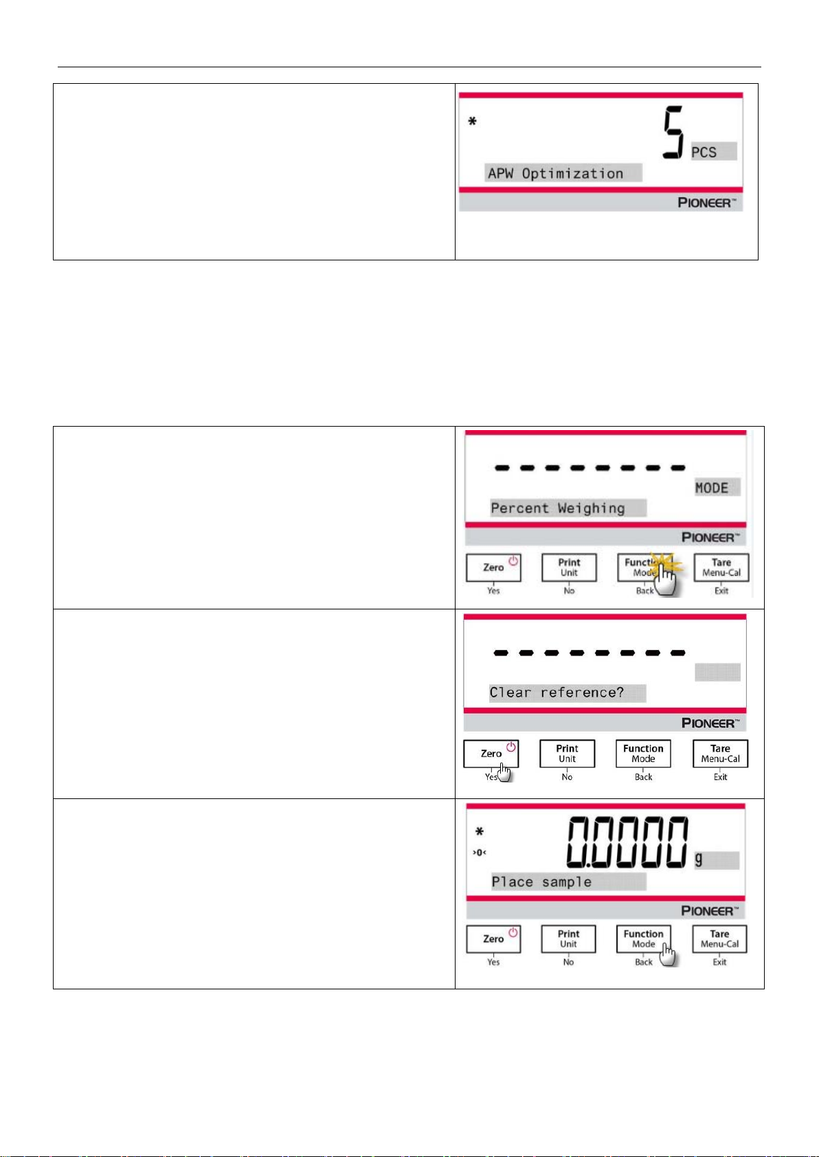
APW Optimization:
Improving counting accuracy by re-calculating the piece weight
automatically as parts are added.
APW Optimization occurs only when the number of pieces
added to the pan is between one and three times the number
already on the pan.
Print Settings:
Changing printing setup. See Section 7 for more information.
1. Press and hold the Function / Mode button until
Percent Weighing appears.
2. After confirmation by pressing Yes, the message
"Clear reference?" will appear on the screen.
3. Press Yes, and then the message "Place sample" will
display.
4. Place the reference sample on the pan to display the
weight. When the reading is stable, the * will appear.
5. Press the Function / Mode button so that the weight
of the reference sample is stored in memory. The
display will show 100%.
4.3 Percent Weighing
Note: Before using any application, be sure the balance has been leveled and calibrated.
Use Percent Weighing to display the weight of a test object as a percentage of a pre-established reference
sample.
The default (or last) reference weight is displayed.
Percent Weighing
Page 13
PX Series Balance EN-11
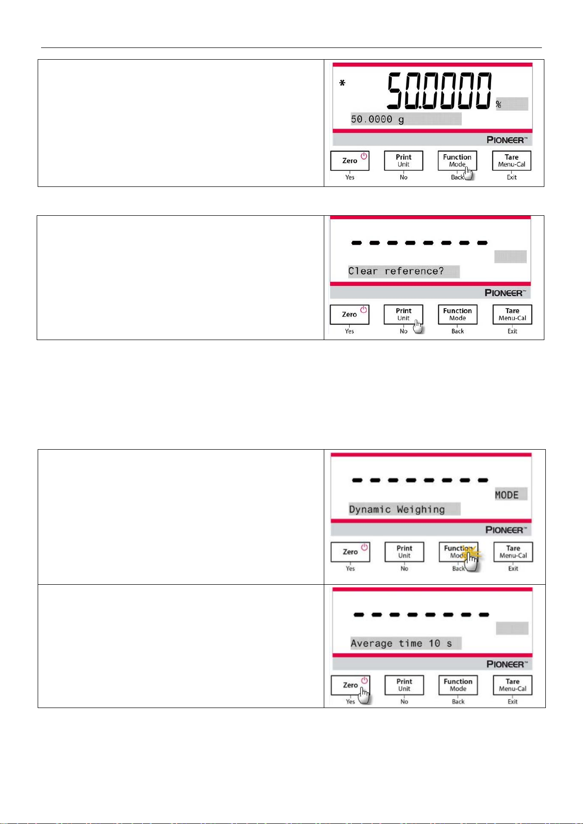
6. Remove the reference sample and place the test
object on the pan. The ratio of the test object to the
reference sample weight is displayed as a
percentage.
7. To view the reference sample weight or the test
object weight, press the Function / Mode button.
1. Press and hold the Function / Mode button until
Dynamic Weighing appears.
2. After confirmation by pressing Yes, the message
"Change parameter?" will appear on the screen.
3. Press Yes, and then the message "Average time 10
s" will display with the numeral "10" flashing. Press
No or Back to increase or decrease the value as
desired.
Note:
If the previously established reference sample weight needs to
be kept, press No when the message "Clear reference?"
displays.
Printing Setup:
Changing printing setup. See Section 7 for more information.
Item Settings
4.4 Dynamic Weighing
Note: Before using any application, be sure the balance has been leveled and calibrated. Clear the pan before
beginning a new Dynamic Weighing cycle.
Use this application to weigh an unstable load, such as a moving animal.
Dynamic Weighing
Page 14
EN-12 PX Series Balance
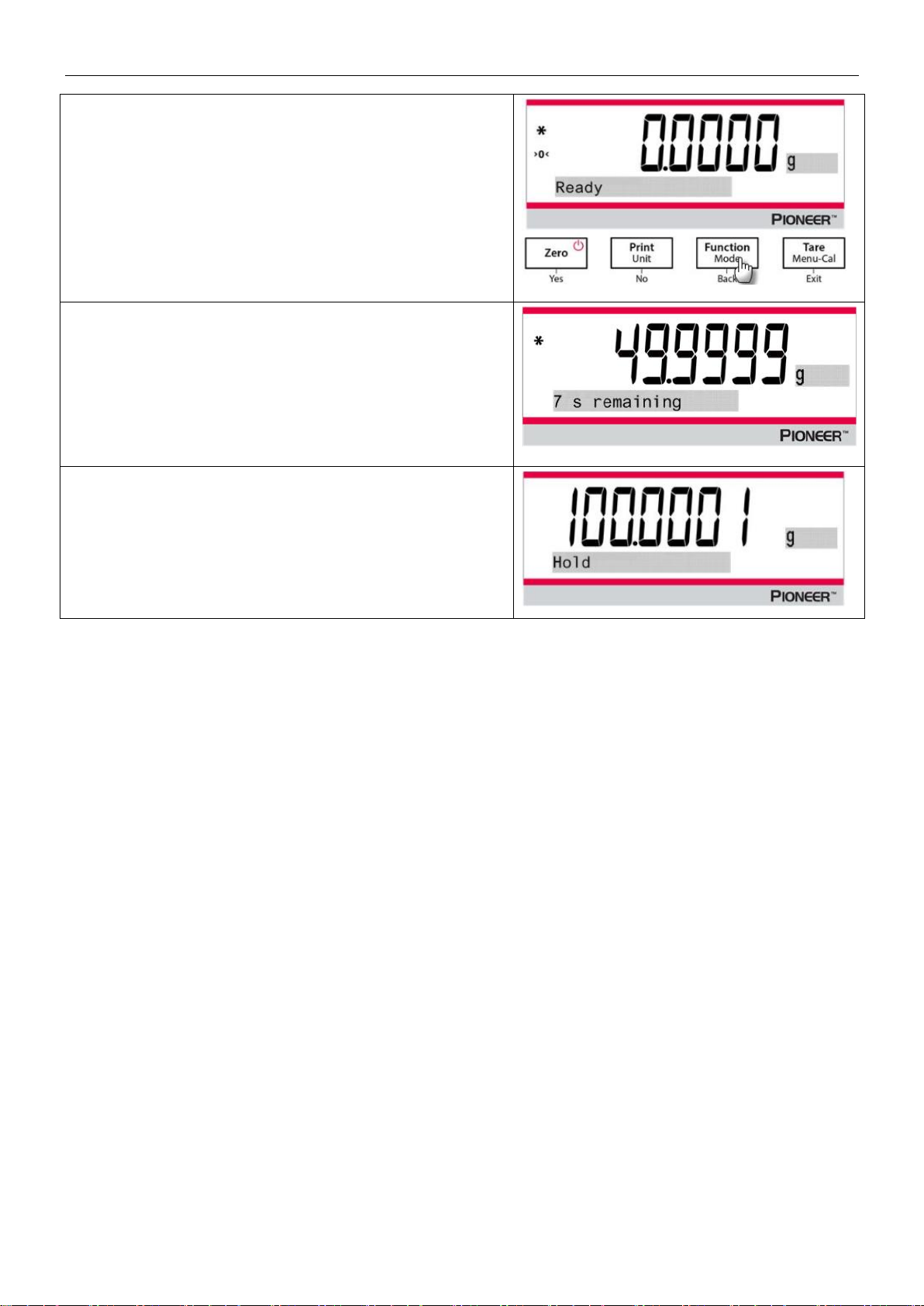
4. Confirm the weighing time by pressing Yes, and the
message "Ready" will display at the lower left of the
screen.
5. Place the dynamic object on the pan. The balance
begins a countdown (averaging process). During the
countdown, the screen shows the time remaining.
6. When the countdown ends, the result line is displayed
and held.
7. After the dynamic object is removed, the weight will
be automatically set to zero, and the balance will
return to the status of "Ready".
Item Settings
1. Averaging Time: Set the averaging time to a value between 1 and 15 seconds. Default is 10 seconds.
2. Printing Setup: Changing printing setup. See Section 7 for more information.
4.5 Density Determination
Note: Before using any application, be sure the balance has been leveled and calibrated.
Use this application to determine an object’s density.
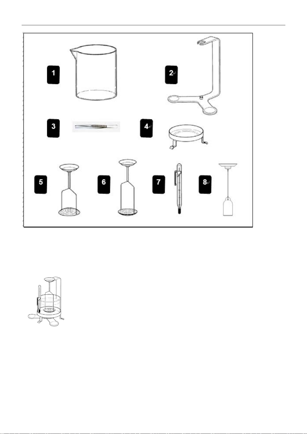
A Density Determination Kit, Part Number 80253384, is designed to be used with PX series balances.
Illustrations in this procedure refer to the density kit, however, you may use whatever lab apparatus that will suit
the requirements for density measurements. A built in reference density table for water at temperatures between
10ºC and 30.9ºC is included in the balance software. Review this entire section before attempting density
measurements.
Page 15
PX Series Balance EN-13
1. Glass beaker
2. Bracket
3. Forceps
4. Platforms
5. Holder for floating solids
6. Holder for non floating solids
7. Precision thermometer with holder
8. Sinker 10ml (optional equipment)
When making density measurements, the material should weigh at least 10.0 mg on an analytical balance and 100
mg on a precision balance.
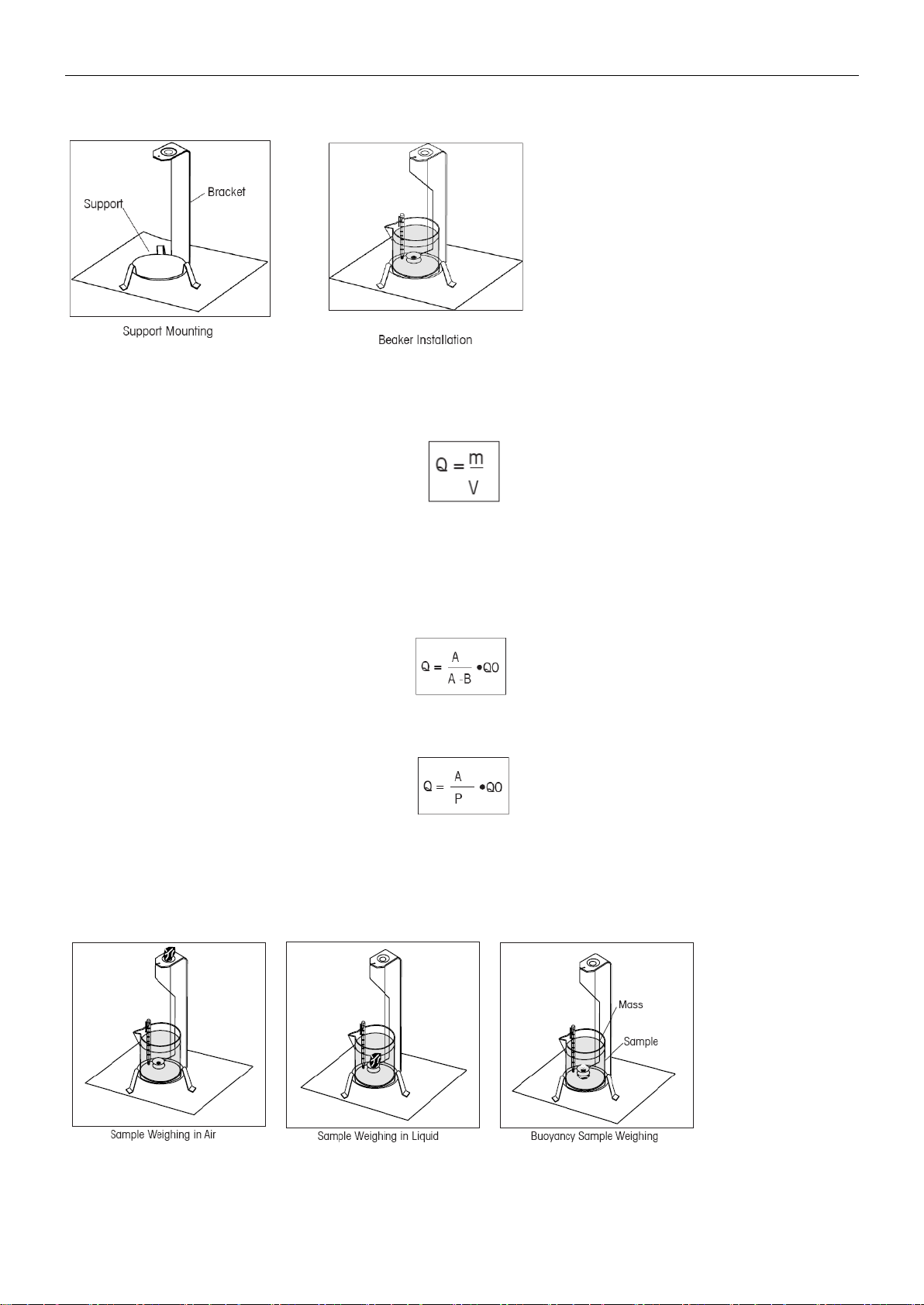
Balance Preparation with Ohaus Density Kit (Optional)
Allow the balance to warm up sufficiently before making measurements.
Open either the left or right side door of the balance and remove the Pan as shown. Insert the Bracket into the
balance where the Pan was removed.
The Equalizing Washer is not used.
Page 16
EN-14 PX Series Balance
Place the Support into position over the bracket making sure the Support does not make contact with the Bracket
as shown in illustration.
Install beaker on support as shown.
NOTE: Beaker and thermometer are not supplied as part of the density kit.
The density Q is the quotient of the mass m and the volume V.
Density determinations are performed by using Archimedes’ principle. This principle states that every solid body
immersed in a fluid loses weight by an amount equal to that of the fluid it displaces. The density table for water is
included in the Discovery balance software.
The density of a solid is determined with the aid of a liquid whose density, Qo, is known (water is used as an
auxiliary liquid). The solid is weighed in air (A) and then in the auxiliary liquid (B). The density Q can be calculated
from the two weighings as follows:
The balance allows direct determination of the buoyancy P (P =A - B) and consequently the above formula can be
simplified:
Q = Density of the solid
A = Weight of the solid in air
B = Weight of the solid in the auxiliary liquid
Q0 = Density of the auxiliary liquid at a given temperature (this value depends on the temperature). The density
table for water is included in Discovery balances.
P = Buoyancy of the solid in the auxiliary liquid (corresponds to A-B).
Page 17
PX Series Balance EN-15
Place the solid in the Weighing Pan on the Weigh Below Hook in the liquid as shown. Ensure that there are no air
bubbles on the solid to be weighed.
Close the draft shield doors and weigh the solid (buoyancy P). The display indicates the density in grams/cc.
Solid Density Determinations for items Less Density Than Water
For density determination of solids with a density less than 1 g/CM3, the bottom of the Weigh Below Hook for solids
must be used as it holds the solid body below the surface of the auxiliary liquid. If the buoyancy of the solid is
greater than the weight of the Weigh Below Hook, the Weigh Below Hook must be weighted by placing an
additional mass on the submerged part of the Weigh Below Hook as shown.
Weigh the sample in air first as explained in the previous procedure.
After loading the additional mass, tare the balance and start the weighing again. Wait until the balance has
reached stability and note the displayed weight P (buoyancy of the solid).
Improving the Accuracy of the Result of Solid Density
The following tips should help you improve the accuracy of the results in the density determination of solids.
Temperature
Solids are generally so insensitive to temperature fluctuations that the corresponding density changes are of no
consequence. However, as work is performed with an auxiliary liquid in the density determination of solids, their
temperature must be taken into account as the temperature has a greater effect with liquids and causes density
changes in the order of magnitude 0.5 to 1% per °C. This effect is already apparent in the third decimal place of the
result.
To obtain accurate results, we recommend that you always take the temperature of the auxiliary liquid into account
on all density determinations.
Air Buoyancy
1 CM3 of air weighs approximately 1.2 mg (depending on the physical condition). As a consequence, in the
weighing in air, each solid experiences buoyancy of this magnitude (the so-called “air buoyancy”) per cm3 of its
volume.
However, the air buoyancy must be taken into account only when a result is required with an accuracy of 3 to 4
decimal places. To correct for this, the air buoyancy (0.0012 g per cm3 volume of the body) is added to the
calculated result:
Calculated density + 0.0012 g/cm3 air buoyancy = effective density
Surface tension of the auxiliary liquid
Adhesion of the liquid to the Weigh Below Hook causes an apparent weight increase of up 3 mg.
As the Weigh Below Hook is immersed in the auxiliary liquid in both weighings of the solid (in air and in the
auxiliary liquid), the influence of the apparent weight increase can be neglected because the balance is tared
before every measurement.
To reduce the effect of air bubbles and to ensure the greatest possible accuracy, use a few drops of a
wetting agent (not supplied) and add them to the auxiliary liquid.
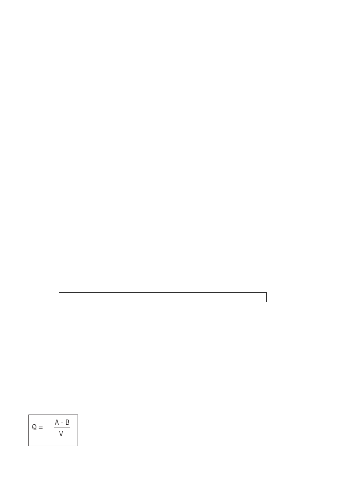
Liquid Density Determinations
The density of a liquid can be made using a sinker of known volume. The sinker (P/N: 83034024) is weighed in air
and then in the liquid whose density is to be determined, The density, Q, can be determined from the two
weighings as follows:
Q = Density of the liquid
A = Weight of the sinker in air
B = Weight of the sinker in liquid
V = Volume of the sinker
P = Buoyancy of the sinker in the liquid (P = A-B)
Page 18

EN-16 PX Series Balance
In DENSITY SETUP, set Mode to Liquid Density and enter sinker volume in cc’s.
After weighing the sinker in air and then weighing the sinker immersed in liquid, the balance calculates the density
of the liquid and is displayed in grams/cc. See illustrations below for placement of the sinker. When the sinker is
immersed in the liquid, it must not come into contact with the bottom of the beaker.
Porous Material Density Determinations
The density of a porous (oil impregnated part) can be made with the balance. Weigh the part (dry) prior to oil
impregnation and record its weight. You must also know the density value of the oil to be used in immersing the
part before starting. In this procedure, you will follow the method for solid density measurements using water.
Enter the dry weight of the porous material and the density of oil used to impregnate the part.
To Determine Wet Density
Wet density of the sample can be calculated by following the normal Solid Density procedure using the oil
impregnated part.
Before density measurements can be made, the density mode of operation must be set up in the Menu, Mode Submenu. It is in the Mode Sub-menu where solid, porous, water or auxiliary liquids are selected.
After the basic parameters have been set, the balance density operation is further determined in the APPL
DENSITY menu. This menu allows the setting of Density, Temperature, Dry Weight of Porous Material, Sinker
Volume and Density of Oil.
Operation Method
Press and hold the Function / Mode button until the Density appears on the screen.
After confirmation by pressing Yes, the message "Change parameter?" will display on the screen. The settings
can be kept or changed as desired.
Item Settings:
Sample Type: Solid, Liquid
Auxiliary Liquid: Water, Alcohol, Other
Porous Material: Off, On
Water Temperature: 20℃ (by default)
Alcohol Temperature: 20℃ (by default)
Volume (of Calibrated Sinker): 10 ml (by default)
Weight (of Porous Material): 5.000 g
Oil Density: 0.80000 g / cm3
Four types of density determination can be made:
1. Solid more density than the auxiliary liquid
2. Solid less density than the auxiliary liquid
3. Liquid density
4. Porous material (impregnated with oil)
The following are the operating procedures for determining density of solid, liquid and porous material with water
as the auxiliary liquid. Other auxiliary liquids are also applicable for density determination.
Page 19

PX Series Balance EN-17
Press and hold the Function / Mode button until Density
appears. Press Yes to initiate the Density Determination.
Item Settings:
Sample type: Solid
Auxiliary Liquid: Water
Porous Material: Off
Water Temperature: Measure the actual water
temperature using a precision thermometer.
The water temperature is 20.0℃ by default.
Press No or Back to increase or decrease the value of
temperature. The balance calculates water density based on
the water temperature value entered.
1. Weigh the sample in air using the balance and the density
determination kit.
When the * (symbol of stability) appears, press the
Function / Mode button to confirm the weight of the
sample in the air.
2. Weigh the sample submerged in the liquid using the
balance and the density determination kit.
Note: Lower the sample down into the liquid until it is fully
submerged.
4.5.1 Measuring the Density of a Sinking Solid Using Water
Page 20

EN-18 PX Series Balance
3. Press the Function / Mode button to get the density of the
sample. After completion of the test, press the Function /
Mode button to test a new sample.
1. Press and hold the Function / Mode button until Density
appears. Press Yes to enter the Density Determination.
2. In determining density with the balance, the balance
setup and density determination procedures are basically
the same for a floating solid and a non-floating solid
except for the necessary holder (as shown in the figure)
to be used for density determination.
3. After completion of the test, press the Function / Mode
button to test a new sample.
Note: Lower the sample down into the liquid until it is fully
submerged.
Holder for non-floating
solids
Holder for floating
solids
1. Press and hold the Function / Mode button until Density
appears. Press Yes to enter the Density Determination.
4.5.2 Measuring the Density of a floating Solid Using Water
4.5.3 Measuring the Density of a Solid Using an Auxiliary Liquid other than Water
Page 21

PX Series Balance EN-19
Item Settings:
Sample type: Solid
Auxiliary Liquid: Other
Porous Material: Off
Set the density of the auxiliary liquid:
2. The default value of the auxiliary liquid is 1.00000 g/cm3.
3. Press No or Back to increase or decrease the value in
accordance with the actual density of the auxiliary liquid.
4. See Section 4.5.1 and Section 4.5.2 for the specific
procedures for density determination.
5. Press the Function / Mode button to display the density of
the sample.
6. After completion of the test, press the Function / Mode
button to test a new sample.
Press and hold the Function / Mode button until Density
appears. Press Yes to enter the Density Determination.
4.5.4 Measuring the Density of a Liquid Using a Calibrated Sinker
Page 22

EN-20 PX Series Balance
Item Settings:
Sample Type: Liquid
Volume: The calibrated sinker has a default volume of 10.0 ml,
which can be increased or decreased by pressing No or Back.
After setting the volume, press Yes to begin the weighing.
Note: when the Density Type is set to Liquid, the Liquid type
and Porous material selections are disabled.
1. Weigh the calibrated sinker in the air with the balance and
the density determination kit.
When the * (symbol of stability) appears, press the
Function / Mode
button to confirm the weight of the
calibrated sinker in the air.
2. Weigh the calibrated sinker submerged in the liquid with
the balance and the density determination kit. Lower the
calibrated sinker down into the liquid until it is fully
submerged (1 cm below the surface of the liquid).
3. When the * (symbol of stability) appears, press the
Function / Mode
button to confirm the weight of the
calibrated sinker. The density of the liquid is displayed.
4. After completion of the test, press the
Function / Mode
button to test a new sample.
Page 23

PX Series Balance EN-21
Press and hold the Function / Mode button until Density
appears. Press Yes to enter the Density Determination.
Item Settings:
Sample type: Solid
Auxiliary Liquid: Water
Porous Material: On
Set the following parameters by pressing
No
or
Back
:
Water Temperature
Weight
Oil Density
Measure the actual water temperature using a precision
thermometer. The balance calculates water density based on
the water temperature value entered.
Note: The weight of the sample and the density of oil must be
measured in advance.
1. Weigh the oiled sample in the air with the balance and the
density determination kit.
2. When the * (symbol of stability) appears, press the
Function / Mode
button to confirm the weight of the oiled
sample in the air.
4.5.5 Measuring the Density of Porous Material Using Oil
Page 24

EN-22 PX Series Balance
3. Weigh the oiled sample in the liquid with the balance and
the density determination kit.
4. When the * (symbol of stability) appears, press the
Function / Mode
button to confirm the weight of the oiled
sample in the liquid. The density of the sample is displayed.
5. After completion of the test, press the
Function / Mode
button to test a new sample.
Page 25

PX Series Balance EN-23
Weigh Below
protective cover
Weigh Below hook
4.6 Additional Features
Weigh Below
Note: Ensure the balance has been leveled and calibrated.
The PX balance is equipped with a weigh below hook for weighing below the balance (as shown in the figure
below).
Before turning the balance over, remove the pan and draft shield elements (if present) to prevent damage. Do not
place the balance on the pan support cone or load cell pins.
To use this feature, remove power from the balance, then remove the protective cover for the weigh below
opening.
Power on the balance, and then use a string or wire to attach items to be weighed.
Page 26

EN-24 PX Series Balance
Calibration
Setup
Units
RS232
Print
GLP
Factory
Reset
Lockout
Internal Cal
Language
Gram
Baud Rate
Stable Only
Header 1
Reset All
Calibration
InCal Adjust
Filter Level
Kilogram
Transmission
Numeric Only
Header 2
Setup
Span Cal
AZT
Milligram
Handshake
Single Header
Header 3
Units
Linearity Cal
Auto Tare
Carat
Print To
Header 4
RS232
Graduations
Newton
Auto Print
Header 5
Print
Date format
Pound
Header
Balance
Name
GLP
Date
Ounce
Date and
Time
User
Name
Factory
Reset
Time Format
Ounce Troy
Balance ID
Project
Name
Time
Grain
Balance
Name
Brightness
Pennyweight
User Name
Auto Dim
Momme
Project Name
Capacity Bar
Mesghal
Application
Name
Approved
Mode
Hong Kong
Tael
Result
Singapore Tael
Gross
Tanwan Tael
Net
Tical
Tare
Tola
Line Feed
5. MENU SETTINGS
5.1 Menu Navigation
TABLE 5-1. USER MENU STRUCTURE
Note: PX balances are classified into InCal models and ExCal models.
5.1.1 Changing Settings
To change a menu setting, navigate to that setting using the following steps:
Enter the Menu
Long press the Menu button to enter the Menu.
Select the Sub-Menu
Press No to step between the sub-menus, and press Yes to enter the sub-menu.
Select the Menu Item
Press No to step through the Menu Items, and press Yes to enter the displayed Menu Item.
5.2 Calibration
PX balances offer a choice of three calibration methods: Internal Calibration (for InCal models only), Span
calibration and Linearity Calibration.
Attention: Do not disturb the balance during any calibration.
5.2.1 Calibration Sub-menu (InCal models)
Note: ExCal models only have Span Calibration and Linearity Calibration.
Page 27

PX Series Balance EN-25
1. Press and hold the Tare / Menu-Cal button, and the
Calibration Menu will display.
5.2.2 Internal Calibration (not applicable to ExCal models)
Calibration is accomplished with the internal calibration mass. Internal Calibration can be performed at any time,
provided the balance has warmed up to operating temperature and is level.
With the Balance turned ON and no load on the pan, the internal calibration can be performed.
Alternatively, press the Tare / Menu-Cal button and select Internal Cal to initiate the internal calibration.
The screen shows the status, and then returns to the current application after calibration.
5.2.3 InCal Adjust (not applicable to ExCal models)
Use this calibration method to fine tune the effect of the Internal Calibration.
Calibration Adjust may be used to adjust the result of the Internal Calibration by +100 divisions.
Note: Before making a calibration adjustment, perform an Internal Calibration. To verify whether an adjustment is
needed, place a test mass equal to the span calibration value on the pan and note the difference (in divisions)
between the nominal mass value and the actual balance reading. If the difference is within +/- division, calibration
adjustment is not required. If the difference exceeds +/-1 division, calibration adjustment is recommended.
Example:
Expected weight reading: 200.000 (Test mass value)
Actual weight reading: 200.014
Difference in gram: – 0.014
Difference in division: – 14 (InCal Adjust value)
To perform a Calibration Adjustment, select InCal Adjustment from the list of Calibration Menu; enter the value
(positive or negative divisions) to match the difference noted earlier in the procedure.
Recalibrate using Internal Calibration. After calibration, place the test mass on the pan and verify that the mass
value now matches the displayed value. If not, repeat the procedure until Internal Calibration reading agrees with
the test mass.
Once completed, the balance stores the Adjustment value and the display returns to the current application.
5.2.4 Span Calibration
Span calibration uses two calibration points, one at zero load and the other at specified full load (span). For
detailed calibration mass information, please see the specification tables in section 9.1.
With the balance turned ON and no load on the pan, Span Calibration can be performed. The best accuracy is
achieved using the mass closest to the full span value.
Steps for span calibration
Page 28

EN-26 PX Series Balance
2. Press Yes to enter the Calibration Menu. To change
the calibration mode, press No until Span Cal (span
calibration) is displayed.
3. Press Yes to begin the span calibration.
4. The calibration masses value will be shown in the
screen. After the display shows "Place weights" and
"100.000 g", place weight(s) of 100 g on the pan for
calibration. To change to the calibration point of half full
capacity (e.g. 50 g), press the Function / Mode button.
After the screen shows "Place weights" and "50.000 g",
place weight(s) of 50 g on the pan for calibration.
5. Remove the weight from the pan.
6. Once the span calibration is completed successfully,
"Calibration done" will display.
Press any button to return to the previous screen.
5.2.5 Linearity Calibration
Linearity calibration uses three calibration points, one at zero load and the others at specified loads.
For detailed calibration mass information, please see the specification tables in section 9.1.
With no load on the scale, Linearity Calibration can be performed.
The balance captures the zero point, and then prompts for the next weight.
Page 29

PX Series Balance EN-27
1. Press and hold the Tare / Menu-Cal button, and the
Calibration Menu will display.
2. Press Yes to enter the Calibration Menu. To change the
calibration mode, press No until Linearity Cal (linearity
calibration) is displayed.
3. Press Yes to begin the linearity calibration.
4. Calibration masses value will be shown in the screen.
After the display shows "Place weights" and "50.0000 g",
place weight(s) of 50 g on the pan for calibration.
5. Remove the weight(s) of 50 g from the pan. After a while,
"100.0000 g" will be displayed on the screen. Please
place weight(s) of 100 g on the pan for calibration.
Continue to follow the instructions on the display until the calibration is completed.
Steps for linearity calibration
Page 30

EN-28 PX Series Balance
6. Once the linearity calibration is completed successfully,
"Linearity done" will display.
Press any button to return to the previous screen.
Set the language displayed for menus and displayed
messages.
English
Chinese
Japanese
Korean
5.3 Balance Setup
Enter this sub-menu to customize balance functionality.
Note: The factory default settings are shown below in bold.
5.3.1 Language
5.3.2 Filter Level
Set the amount of signal filtering.
Low = faster stabilization time with less stability.
Medium = normal stabilization time with normal stability.
High = slower stabilization time with more stability.
5.3.3 AZT (Auto Zero Tracking)
Set the automatic zero tracking functionality.
Off = disabled.
0.5 d = display maintains zero up to a drift of 0.5 graduation per second.
1 d = display maintains zero up to a drift of 1 graduation per second.
3 d = display maintains zero up to a drift of 3 graduations per second.
5.3.4 Auto Tare
Set the automatic tare.
Off = disabled.
On = enabled.
Note: "Place container" will be displayed when Automatic Tare is set to On.
Page 31

PX Series Balance EN-29
5.3.5 Graduations
Set the displayed readability of the balance.
1 Division = standard readability.
10 Divisions = readability is increased by a factor of 10.
For example, if the standard readability is 0.01g, selecting 10 Divisions will result in a displayed reading of 0.1 g.
5.3.6 Date Format
Set the current date format.
YYYY/MM/DD
MM/DD/YYYY
DD/MM/YYYY
5.3.7 Date Setup
Set the date in the current date format.
For example, if the date format is MM/DD/YYYY, the date could be set as "06/22/2017 Thu".
5.3.8 Time Format
Set the current time format.
24HR
12HR
5.3.9 Time Setup
Set the time in the current time format.
For example, if the time format is 24HR, the time could be set as 08:00:00.
5.3.10 Brightness
Set the brightness of the display.
Low
Medium
High
5.3.11 Auto Dim
Set whether the balance automatically turns off the display backlight of the display.
Off = disabled
10 minutes = become dim if there is no motion for 10 minutes
20 minutes = become dim if there is no motion for 20 minutes
30 minutes = become dim if there is no motion for 30 minutes
5.3.12 Capacity Bar
Off = disabled
On = enabled
When the capacity is set On, a capacity bar will display at the bottom of the screen. The capacity bar will roughly
show the current weight as a percentage of balance capacity. When the display is at zero, the capacity bar will not
display.
Page 32

EN-30 PX Series Balance
Display
Unit
Display
Unit
g
Gram
dwt
Pennyweight
kg
Kilogram
mo
Momme
t
Ton
msg
Mesghal
mg
Milligram
tl H
HK tael
ug
Microgram
tl S
SG tael
ct
Carat
tl T
TW tael
N
Newton
tcl
Tical
lb
Pound
tola
Tola
oz
Ounce
baht
Baht
ozt
Troy ounce
lboz
lb:oz
GN
Grain
5.3.13 Approved Mode
Use this menu to set the Legal for Trade status.
Off = standard operation.
Note: When Approved Mode is set to On, the menu settings are affected as follows:
Calibration Menu:
Balance Setup Menu:
Communication Menu (Communication->Print Settings->Print Output):
Communication Menu (Communication->Print Settings->Auto Print):
Lockout Menu:
Note: The security switch located at the rear of the balance must be in the locked position to set Approved Mode to
On. The security switch must be in the unlocked position to set Approved Mode to Off. See Section 6.
On = operation complies with Legal Metrology regulations.
For InCal models, only Internal Calibration is available. All other functions are hidden.
Filter Level is locked at the current setting.
Auto Zero Tracking is limited to 0.5 Division and Off. The selected setting is locked.
Auto Tare is locked at current setting.
Graduations are forced to 1 Division and the menu item is hidden.
Stable Weight Only is locked On.
Numeric Value Only is locked Off.
Auto print mode selections are limited to Off, On Stability, and Interval. Continuous is not available.
Menu is hidden
5.4 Weighing Units
Enter this sub-menu to activate the desired units of measure.
PX balances provide a choice of 21 units, which are all set On by default.
Note: Due to national laws, the balance may not include some of the units of measure listed.
Page 33

PX Series Balance EN-31
1. Press and hold the Print / Unit button until the Unit Menu is
displayed.
2. The default unit is gram (g). To change the unit, press No
to advance to the next unit.
3. Press Yes to set the unit displayed to the weighing unit.
Changing Weighing Units
Defining Custom Unit
Set Custom to On in the Unit menu to enable and define the Custom Unit.
The Custom Unit is defined by entering three parameters, Factor, Exponent and LSD (least significant digit).
Define the Custom Unit as follows:
1. Determine how many custom units there are in 1 gram.
2. Convert the value to scientific notation, e.g. m x 10n.
3. Enter the value of m as the Factor setting.
4. Enter the value of n as the Exponent setting.
5. Enter the amount that the Custom Unit steps by as the LSD setting.
Enter the Factor and the Exponent and LSD.
Page 34

EN-32 PX Series Balance
LSD
Result
1
5
10
…
Display counts by 1
Display counts by 5
Display counts by 10
…
Custom Unit = Conversion Factor x Grams.
The LSD is the value by which the displayed weight is incremented or decremented.
Note:
The conversion factor is used by the balance to convert grams to the custom weighing unit and is defined by
entering a factor and an exponent. The factor is a value between 0.1000000 and 1.999999 inclusive.
For example: One cup of chemical = 0.5643834×1 g, the factor should be set 0.5643834.
The exponent moves the decimal point of the factor to the right for positive values or to the left for negative values.
For example: One cup of chemical = 10 g, the exponent should be set 2.
The LSD is the value by which weight is incremented or decremented.
For example, if the displayed digital is 0.56 for one cup of chemical, the LSD should be set 100.
5.5 RS232 Interface Setup
Enter this sub-menu to customize RS232 standard settings. Data may be output to either a printer or a PC.
5.5.1 Baud Rate
Set the baud rate (bits per second).
1200 = 1200 bps
2400 = 2400 bps
4800 = 4800 bps
9600 = 9600 bps
19200 = 19200 bps
38400 = 38400 bps
5.5.2 Transmission
Set the data bits, stop bit, and parity.
8-NO-1 = 8 data bits, no parity, stop bit 1
8-NO-2 = 8 data bits, no parity, stop bit 2
7-EVEN-1 = 7 data bits, even parity, stop bit 1
7-EVEN-2 = 7 data bits, even parity, stop bit 2
7-NO-1 = 7 data bits, no parity, stop bit 1
Page 35

PX Series Balance EN-33
7-NO-2 = 7 data bits, no parity, stop bit 2
7-ODD-1 = 7 data bits, odd parity, stop bit 1
7-ODD-2 = 7 data bits, odd parity, stop bit 2
5.5.3 Handshake
Set the flow control method.
None = no handshaking
Xon-Xoff = XON/XOFF handshaking
Hardware = hardware handshaking
5.6 Print Settings
Enter this sub-menu to customize data transfer settings.
5.6.1 Stable Only
Off = values are printed immediately, regardless of stability.
5.6.2 Numeric Only
On = values are printed only when the stability criteria are met.
Off = All selected results are printed.
On = Only numeric data values are printed.
5.6.3 Single Header
Off = Headers will be printed for every print requirement.
On = Headers will be printed once a day.
5.6.4 Print To
PC = print data to a PC
Printer = print data to a printer
5.6.5 Auto Print
Off = disabled
On Stability1 = printing occurs each time the stability criteria are met.
Print Interval2 = printing occurs at the defined time interval.
Continuous = printing occurs continuously.
1
When On Stability is selected, set the conditions for printing.
Load = Prints when the displayed load is stable.
Load and Zero = Prints when the displayed load and zero readings are stable.
2
When Print Interval is selected, set the time interval using the numeric keypad.
Settings of 1 to 3600 seconds are available. Default is 0.
5.6.6 Header
On = the header is printed.
Off = the header is not printed.
5.6.7 Date and Time
On = the date and the time are printed.
Off = neither the date nor the time is printed.
Page 36

EN-34 PX Series Balance
5.6.8 Balance ID
On = the balance ID is printed.
Off = the balance ID is not printed.
5.6.9 Balance Name
On = the balance name is printed.
Off = the balance name is not printed.
5.6.10 User Name
On = the user name is printed.
Off = the user name is not printed.
5.6.11 Project Name
On = the project name is printed.
Off = the project name is not printed.
5.6.12 Application Name
On = the application name is printed.
Off = the application name is not printed.
5.6.13 Result
On = the weighing result is printed.
Off = the weighing result is not printed.
5.6.14 Gross
On = the gross weight is printed.
Off = the gross weight is not printed.
5.6.15 Net
On = the net weight is printed.
Off = the net weight is not printed.
5.6.16 Tare
On = the tare weight is printed.
Off = the tare weight is not printed.
5.6.17 Line Feed
1 Line = move the paper up one line after printing.
4 Lines = move the paper up four lines after printing.
Page 37

PX Series Balance EN-35
5.7 GLP
Enter this menu to set the Good Laboratory Practices (GLP).
5.7.1 Header
Enables the printing of GLP headings. There are up to 5 headings available.
Alphanumeric settings up to 25 characters are available for each Header setting
5.7.2 Balance Name
Set the balance name.
Alphanumeric settings up to 16 characters are available.
5.7.3 User Name
Set the user name.
Alphanumeric settings up to 16 characters are available. The default is blank.
5.7.4 Project Name
Set the project name.
Alphanumeric settings up to 16 characters are available. The default is blank.
5.8 Factory Reset
Use this sub-menu to reset the all menu settings to their Factory default settings.
Reset All = resets all menus to their factory default settings.
Exit = return to application main screen without resetting any menus.
5.9 Lockout
Use this sub-menu to lock/unlock certain menus.
Off = the menu is unlocked
On = the menu is locked
Page 38

EN-36 PX Series Balance
Un-locked
Locked with Paper Seal
Locked with Wire Seal
6. LEGAL FOR TRADE (LFT)
When the balance is used in trade or a legally controlled application it must be set up, verified and sealed in
accordance with local weights and measures regulations. It is the responsibility of the purchaser to ensure that all
pertinent legal requirements are met.
6.1 Settings
Before the verification and sealing perform the following steps:
1. Verify the menu settings meet the local weights and measures regulations.
2. Perform a calibration as explained in Section 5.
3. Set the position of the security switch as shown in Section 6.3.
Note: When the security switch is set on the following menu settings cannot be changed: calibration, setup, mode,
unit and lockout. For more details, see Section 5.3.13.
6.2 Verification
The local weights and measures official or authorized service agent must perform the verification procedure.
6.3 Securing the Menu
A slide switch is used to secure the Lock menu settings. When the switch is set to the On position, the Lock menu
settings may be viewed but not changed. This switch is located behind the Base.
Set the position of the switch to ON by sliding the external Lock Switch to LOCKED as shown in the figure below.
Note: This switch is also used in conjunction with the Legal for Trade menu item. When the Legal for Trade menu
is set to ON, the switch must be set to the On position to prevent calibration and changes to metrologically
significant settings.
6.4 Sealing Access to the Balance Settings
The local weights and measures official or authorized service agent must apply a security seal to prevent
tampering with the settings. Refer to the illustrations below for the sealing methods.
Page 39

PX Series Balance EN-37
Use the built-in RS-232 Port to connect either to a computer or a printer.
If connecting to a computer, use HyperTerminal or similar software like SPDC
described below.
(Find HyperTerminal under Accessories/Communications in Windows XP.)
Connect to the computer with a standard (straight-through) serial cable.
Choose New Connection, “connect using” COM1 (or available COM port).
Select Baud=9600; Parity=8 None; Stop=1; Handshaking=None. Click OK.
Choose Properties/Settings, then ASCII Setup. Check boxes as illustrated:
(Send line ends…; Echo typed characters…; Wrap lines…)
Use RS232 Interface Commands (Section 9.6.1) to control the balance from a PC.
SPDC Software
The Serial Port Data Collection / SPDC software is provided by Ohaus and can be used on operating systems that
do not have the HyperTerminal software mentioned above. SPDC software can preliminarily collect and transfer
the data to Microsoft files (such as Excel, Word, etc.).
Choose the export file type and export file path and then press Run as shown below.
Note: The latest SPDC software support English and Chinese language and can be downloaded from the Ohaus'
website. For more information, refer to the SPDC Data Collection Instruction Manual.
7. Printing
7.1 Connecting, Configuring and Testing the Printer / Computer Interface
Page 40

EN-38 PX Series Balance
Field:
Label 1
Space 2
Weight 3
Space2
Unit 4
Space
Stability 5
Space
G/N 6
Space
Term.
Characters 7
Length:
1 11 1 5
1
1
1
3 0 8
BASIC WEIGHING
PART COUNTING
PERCENT WEIGHING
Header 1
Header 2
Header 3
Header 4
Header 5
07/19/2017 17:56:23
Balance ID: B234567890
Balance Name: PX5202
User Name:
Project Name:
Weighing
49.98 g
Gross: 49.98 g G
Net: 49.98 g N
Tare: 0.00 g T
Signature: ____________
Verified By: ____________
Header 1
Header 2
Header 3
Header 4
Header 5
07/19/2017 17:57:19
Balance ID: B234567890
Balance Name: PX5202
User Name:
Project Name:
Parts Counting
Quantity: 4999 PCS
Gross: 49.99 g G
Net: 49.99 g N
Tare: 0.00 g T
APW: 0.010 g
Sample Size: 10 PCS
Signature: ____________
Verified By: ____________
Header 1
Header 2
Header 3
Header 4
Header 5
07/19/2017 17:57:19
Balance ID: B234567890
Balance Name: PX223/E
User Name:
Project Name:
Percent Weighing
Percentage: 10.156 % N
Gross: 23.361 g G
Net: 10.156 g N
Tare: 13.205 g T
Reference weight: 100.000 g
Signature: ____________
Verified By: ____________
7.2 Output Format
The Result Data, and G/N/T data, is output in the following format.
Note:
1. The length of the label field is not fixed.
2. Each field is followed by a single delimiting space (ASCII 32).
3. The Weight field is 11 right justified characters. If the value is negative, the '–' character is located at the
immediate left of the most significant digit.
4. The Unit field contains the unit of measure abbreviation up to 5 characters, right justified.
5. The Stability field contains the “?” character if the weight reading is not stable. The Stability field and the
following Space field are omitted if the weight reading is stable.
6. The G/N field contains the net or gross indication. For net weights, the field contains “N”. For gross
weights, the field contains “G”.
7. The Termination Characters field contains CRLF, Four CRLF or Form Feed (ASCII 12), depending on
the LINE FEED menu setting.
8. When Numeric Only is set On, only the Weight Field is printed, left-aligned.
7.3 Printout Examples
Examples for each Application are shown with all items turned ON in the Print menu. The default values for
Header lines 1-5 are also shown.
Page 41

PX Series Balance EN-39
DYNAMIC WEIGHING
DENSITY
(Density Type=Solid, auxiliary
liquid=water,porous material=on)
DENSITY
(Density Type=liquid, sinker
volume=10ml)
-OHAUS03/19/2000 04:51:46
Balance ID:
Balance Name: PX2202ZH/E
User Name:
Project Name:
---Span Calibration--Calibration is done.
Reference weight: 2000.00 g
Actual weight: 2000.22 g
Difference weight: 0.22 g
Weight ID: ____________
Signature: ____________
Verified By: ____________
-OHAUS01/01/2000 17:30:47
Balance ID:
Balance Name: PX5202M
User Name:
Project Name:
---Linearity Calibration--Calibration is done.
Signature: ____________
Verified By: ____________
-OHAUS07/26/2017 05:16:53
Balance ID:
Balance Name: PX2202
User Name:
Project Name:
---Internal Calibration--Calibration is done.
Difference weight: 0.00 g
Signature: ____________
Verified By: ____________
Header 1
Header 2
Header 3
Header 4
Header 5
07/19/2017 18:00:12
Balance ID: B234567890
Balance Name: PX5202
User Name:
Project Name:
Dynamic Weighing
Final weight: 49.99 g
Gross: 50.06 g G
Net: 50.06 g N
Tare: 0.00 g T
Averaging Time: 10 s
Signature: ____________
Verified By: ____________
Header 1
Header 2
Header 3
Header 4
Header 5
07/19/2017 18:03:23
Balance ID: B234567890
Balance Name: PX5202
User Name:
Project Name:
Density
Density: 0.0345 g/cm³
Gross: 49.99 g G
Net: 49.99 g N
Tare: 0.00 g T
Oiled Weight: 199.89 g
Weight in liquid: 49.98 g
Auxiliary liquid: Water
liquid density: 0.9982 g/cm³
Temp.: 20.0 ℃
Porous: On
Oil density: 0.8000 g/cm³
Dry Weight: 5.00 g
Signature: ____________
Verified By: ____________
Header 1
Header 2
Header 3
Header 4
Header 5
07/19/2017 18:05:17
Balance ID: B234567890
Balance Name: PX5202
User Name:
Project Name:
Density
Density: 14.9820 g/cm³
Gross: 49.98 g G
Net: 49.98 g N
Tare: 0.00 g T
Weight in air: 199.88 g
Weight in liquid: 50.05 g
Sinker Volume: 10.0 ml
Signature: ____________
Verified By: ____________
INTERNAL CALIBRATION SPAN CALIBRATION LINEARITY CALIBRATION
Page 42

EN-40 PX Series Balance
WARNING: Disconnect the balance from the power supply before cleaning.
Make sure that no liquid enters the interior of the balance.
Symptom / Display
Possible Cause
Remedy
Balance will not turn on
No power to the balance
Verify connection and
voltage
Poor accuracy
Improper calibration
Unstable environment
Perform calibration
Move balance to suitable
location
Cannot calibrate
Calibration Menu locked
Approved Mode set to on
Unstable environment
Incorrect calibration masses
Turn Calibration menu lock
off
Turn Approved Mode off
Move balance to suitable
location
Use correct calibration
masses
Cannot change menu
settings
Sub-menu locked
Approved Mode set to on
Unlock sub-menu
Turn Approved Mode off
Low Reference weight
Reference weight too small
The weight on the pan is too small to define a valid
reference weight.
Increase sample size
Invalid Piece Weight
Average piece weight is too small
Increase average piece
weight
Operation Timeout
Weight reading is not stable
Move balance to suitable
location
Err 8.3
Weight reading exceeds overload limit.
Remove weight from the pan
Err 8.4
Weight reading below underload limit.
Re-install the pan
------
Busy (tare, zero, printing, waiting for a stable weight)
Wait until completion
8. MAINTENANCE
8.1 Calibration
Periodically verify calibration by placing an accurate weight on the balance and viewing the result. If calibration is
required, refer to section 5.2 for instructions.
8.2 Cleaning
Clean the balance at regular intervals.
Housing surfaces may be cleaned with a lint-free cloth slightly dampened with water or a mild cleaning
agent.
Glass surfaces may be cleaned with a commercial glass cleaner.
Attention: Do not use solvents, harsh chemicals, ammonia or abrasive cleaning agents.
8.3 Troubleshooting
TABLE 8-1. TROUBLESHOOTING
8.4 Service Information
If the troubleshooting section does not resolve your problem, contact an Authorized Ohaus Service Agent. Please
visit our website www.ohaus.com to locate the Ohaus office nearest you.
Page 43

PX Series Balance EN-41
9. TECHNICAL DATA
9.1 Specifications
Ambient conditions
Indoor use only
Altitude: Up to 2000 m
Specified Temperature range: 10°C to 30°C
Humidity: maximum relative humidity 80% for temperatures up to 30°C, decreasing linearly to 50% relative
humidity at 40°C
Operability is assured at ambient temperatures between 5°C and 40°C
Mains supply voltage fluctuations: up to ±10% of the nominal voltage
Installation category II
Pollution degree: 2
Supply voltage: 12V⎓0.5A
Materials
Bottom Housing: Die-cast Aluminum, Painted
Top Housing: Plastic (HIPS)
Weighing Platforms: Stainless steel
Draft Shield: Glass, plastic (HIPS)
Feet: Plastic (ABS)
Page 44

EN-42 PX Series Balance
InCal Model
PX85
PX125D
PX225D
PX84
PX124
PX224
PX163
ExCal Model
PX84/E
PX124/E
PX224/E
PX163/E
Capacity (g)
82
52/120
82/220
82
120
220
160
Readability d (g)
0.00001
0.00001/
0.0001
0.00001/
0.0001
0.0001
0.0001
0.0001
0.001
Repeatability (STDEV) (g)
0.00002
0.00002/
0.0001
0.00002/
0.0001
0.0001
0.0001
0.0001
0.001
Linearity (g)
±0.0001
±0.0001
±0.0001
±0.0002
±0.0002
±0.0002
±0.002
Stabilization Time Typical
(s)
10
10
10
4 4 4
2
Sensitivity Temperature
Drift (PPM/K)
±0.8
±0.8
±0.8
±3
±3
±3
±8
Typical Minimum Weight
USP
(USP K=2,U=0.10%)
20 mg
20 mg
20 mg
200 mg
200 mg
200 mg
2 g
Optimized Min-Weight (g)
(USP, u=0.10%, k=2)
SRP≤0.41d*
9 mg
9 mg
9 mg
82 mg
82 mg
82 mg
0.82 g
Units
Milligram, Gram, Kilogram, Ounce, Pound, Carat, Pennyweight, Ounce Troy, Grain,
Newton, Hong Kong Tael, Singapore Tael, Taiwan Tael, Momme, Tical (MM),
Mesghal, Tola (India), 1 Custom unit
Applications
Basic Weighing, Parts Counting, Percent Weighing, Dynamic Weighing, Density
Determination
Platform Size (diameter,
mm)
80
80
80
90
90
90
120
Span Calibration Points (g)
40, 80
50, 100
100, 200
40, 80
50, 100
100, 200
80, 160
Linearity Calibration Points
(g)
20, 40,
60, 80
50, 75,
100
50, 100,
150, 200
20, 40,
60, 80
50, 75,
100
50, 100,
150, 200
40,
80,120,16
0
Tare Range
To capacity by subtraction
Power Supply
Power input: 100-240V ~ 200mA 50-60Hz 12-18VA
Power output: 12 VDC 0.5A
Assembled Dimensions
(W x D x H) (mm)
209 x 321 x 309
Communication
RS232, USB
Operating Temperature
Range
15°C to 25°C
10°C to 30°C
Storage Temperature
Range
Humidity: maximum relative humidity 80 % for temperatures up to 30°C,
decreasing linearly to 50% relative humidity at 40°C
Storage Conditions
-10°C to 60°C, humidity 10% to 90%, without condensation
Net Weight
10 lb / 4.5 kg
Shipping Weight
15.4 lb / 7 kg
Shipping Dimensions
(W x D x H) (mm)
507 x 387 x 531
TABLE 9-1. SPECIFICATIONS
Note:
*SRP refers to the standard deviation for n replicate weighings (n≥10).
Page 45

PX Series Balance EN-43
InCal Model
PX223
PX323
PX423
PX523
PX822
PX1602
PX2202
ExCal Model
PX223/E
PX323/E
PX423/E
PX523/E
PX822/E
PX1602/E
PX2202/E
Capacity (g)
220
320
420
520
820
1600
2200
Readability d (g)
0.001
0.001
0.001
0.001
0.01
0.01
0.01
Repeatability
(STDEV) (g)
0.001
0.001
0.001
0.001
0.01
0.01
0.01
Linearity (g)
±0.002
±0.002
±0.002
±0.002
±0.02
±0.02
±0.02
Stabilization Time
Typical (s)
2 2 2 2 1 1 1
Sensitivity
Temperature Drift
(PPM/K)
±9
±3
±3
±3
±6
±6
±6
Typical Minimum
Weight USP
(USP K=2,U=0.10%)
2 g
2 g
2 g
2 g
20 g
20 g
20 g
Optimized Min-Weight
(g)
(USP, u=0.10%, k=2)
SRP≤0.41d*
0.82 g
0.82 g
0.82 g
0.82 g
8.2 g
8.2 g
8.2 g
Units
Milligram, Gram, Kilogram, Ounce, Pound, Carat, Pennyweight, Ounce Troy, Grain,
Newton, Hong Kong Tael, Singapore Tael, Taiwan Tael, Momme, Tical(MM), Mesghal,
Tola(India), 1 Custom unit
Applications
Basic Weighing, Parts Counting, Percent Weighing, Dynamic Weighing, Density
Determination
Platform Size
(diameter, mm)
120
120
120
120
180
180
180
Span Calibration
Points (g)
100, 200
150, 300
200, 400
250, 500
400, 800
750, 1500
1000,
2000
Linearity Calibration
Points (g)
50, 100,
150, 200
100, 200,
300
100, 200,
300, 400
200, 300,
400, 500
200, 400,
600, 800
500, 1000,
1500
500, 1000,
1500,
2000
Tare Range
To capacity by subtraction
Power Supply
Power input: 100-240V ~ 200mA 50-60Hz 12-18VA
Power output: 12 VDC 0.5A
Assembled
Dimensions
(W x D x H) (mm)
209 x 321 x 309
209 x 321 x 98
Communication
RS232, USB
Operating
Temperature Range
10°C to 30°C
Storage Temperature
Range
Humidity: maximum relative humidity 80% for temperatures up to 30°C,
decreasing linearly to 50% relative humidity at 40°C
Storage Conditions
-10°C to 60°C, humidity 10% to 90%, without condensation
Net Weight
10 lb / 4.5 kg
7.7 lb / 3.5 kg
Shipping Weight
15.4 lb / 7 kg
11 lb / 5 kg
Shipping Dimensions
(W x D x H) (mm)
507 x 387 x 531
550 x 385 x 291
TABLE 9-2. SPECIFICATIONS (continued)
Note: *SRP refers to the standard deviation for n replicate weighings (n≥10).
Page 46

EN-44 PX Series Balance
InCal Model
PX3202
PX4202
PX5202
PX2201
PX4201
ExCal Model
PX3202/E
PX4202/E
PX5202/E
PX2201/E
PX4201/E
PX6201/E
PX8201/E
Capacity (g)
3200
4200
5200
2200
4200
6200
8200
Readability d (g)
0.01
0.01
0.01
0.1
0.1
0.1
0.1
Repeatability
(STDEV) (g)
0.01
0.01
0.01
0.1
0.1
0.1
0.1
Linearity (g)
±0.02
±0.02
±0.02
±0.2
±0.2
±0.2
±0.2
Stabilization Time
Typical (s)
1 1 1 1 1 1 1
Sensitivity
Temperature Drift
(PPM/K)
±3
±3
±3
±10
±10
±10
±10
Typical Minimum
Weight USP
(USP K=2,U=0.10%)
20 g
20 g
20 g
200 g
200 g
200 g
200 g
Optimized MinWeight (g)
(USP, u=0.10%, k=2)
SRP≤0.41d*
8.2 g
8.2 g
8.2 g
82 g
82 g
82 g
82 g
Units
Milligram, Gram, Kilogram, Ounce, Pound, Carat, Pennyweight, Ounce Troy, Grain,
Newton, Hong Kong Tael, Singapore Tael, Taiwan Tael, Momme, Tical (MM), Mesghal,
Tola (India), 1 Custom unit
Applications
Basic Weighing, Parts Counting, Percent Weighing, Dynamic Weighing, Density
Determination
Platform Size
(diameter, mm)
180
180
180
180
180
180
180
Span Calibration
Points (g)
1500, 3000
2000, 4000
2500, 5000
1000, 2000
2000, 4000
3000, 6000
4000, 8000
Linearity Calibration
Points (g)
1000, 2000,
3000
1000, 2000,
3000, 4000
2000, 3000,
4000, 5000
500, 1000,
1500, 2000
1000, 2000,
3000, 4000
2000, 4000,
6000
2000, 4000,
6000, 8000
Tare Range
To capacity by subtraction
To capacity by subtraction
Power Supply
Power input: 100-240V ~ 200mA 50-60Hz 12-18VA
Power output: 12 VDC 0.5A
Assembled
Dimensions
(W x D x H) (mm)
209 x 321 x 98
Communication
RS232, USB
Operating
Temperature Range
10°C to 30°C
Storage Temperature
Range
Humidity: maximum relative humidity 80 % for temperatures up to 30°C,
decreasing linearly to 50% relative humidity at 40°C
Storage Conditions
-10°C to 60°C, humidity 10% to 90%, without condensation
Net Weight
7.7 lb / 3.5 kg
Shipping Weight
11 lb / 5 kg
Shipping Dimensions
(W x D x H) (mm)
550 x 385 x 291
TABLE 9-3. SPECIFICATIONS (continued)
Note:
*SRP refers to the standard deviation for n replicate weighings (n≥10).
Page 47

PX Series Balance EN-45
InCal Approval Model
PX125DM
PX124M
PX224M
PX323M
PX523M
PX3202M
PX5202M
PX4201M
PX225DM
PX85M
Capacity (g)
52/120
120
220
320
520
3200
5200
4200
82/220
82
Readability d (g)
0.00001/
0.0001
0.0001
0.0001
0.001
0.001
0.01
0.01
0.1
0.00001
0.00001
Verification Interval e (g)
0.001
0.001
0.001
0.01
0.01
0.1
0.1
0.1
0.001
0.001
Class
I I I
II
II
II
II
II I I
Repeatability (STDEV) (g)
0.00002/
0.0001
0.0001
0.0001
0.001
0.001
0.01
0.01
0.1
0.00002/
0.0001
0.00002
Linearity (g)
±0.0001
±0.0002
±0.0002
±0.002
±0.002
±0.02
±0.02
±0.2
±0.0001
±0.0001
Stabilization Time Typical
(s)
10 4 4 2 2 1 1 1 10
10
Sensitivity temperature
drift (PPM/K)
±0.8
±3
±3
±3
±3
±3
±3
±10
±0.8
±0.8
Typical Minimum Weight
USP
(USP K=2,U=0.10%)
20 mg
200 mg
200 mg
2 g
2 g
20 g
20 g
200 g 20 mg
20 mg
Optimized Min-Weight (g)
(USP, u=0.10%, k=2) SRP
≤ 0.41d*
9 mg
82 mg
82 mg
0.82 g
0.82 g
8.2 g
8.2 g
82 g
9 mg
9 mg
Units
g, mg , ct
g, kg , ct
Applications
Basic Weighing, Parts Counting, Percent Weighing, Dynamic Weighing, Density Determination
Platform Size (diameter,
mm)
80
90
90
120
120
180
180
180
80
80
Span Calibration Points
(g)
50, 100
50, 100
100, 200
150, 300
250, 500
1500,
3000
2500,
5000
2000,
4000
100, 200
40, 80
Linearity Calibration
Points (g)
50, 75, 100
50, 75,
100
50, 100,
150, 200
100, 200,
300
200, 300,
400, 500
1000,
2000,
3000
2000,
3000,
4000,
5000
1000,
2000,
3000,
4000
50. 100,
150, 200
20, 40,
60, 80
Tare Range
To capacity by subtraction
Power Supply
Power input: 100-240V ~ 200mA 50-60Hz 12-18VA
Power output:12 VDC 0.5A
Assembled Dimensions
(W x D x H) (mm)
209 x 321 x 309
209 x 321 x 98
Communication
RS232, USB
Operating Temperature
Range
15°C to
25°C
10°C to 30°C
15°C to 25°C
Storage Temperature
Range
Humidity: maximum relative humidity 80% for temperatures up to 30°C, decreasing linearly to 50% relative humidity at 40°C
Storage Conditions
-10°C to 60°C, humidity 10% to 90%, without condensation
Net Weight
10 lb / 4.5 kg
7.7 lb / 3.5 kg
Shipping Weight
15.4 lb / 7 kg
11 lb / 5 kg
Shipping Dimensions
(W x D x H) (mm)
507 x 387 x 531
550 x 385 x 291
TABLE 9-4. SPECIFICATIONS (continued)
Note:
*SRP refers to the standard deviation for n replicate weighings (n≥10).
Page 48

EN-46 PX Series Balance
DESCRIPTION
PART NUMBER
Auxiliary Display PAD7
80251396
Density Kit
80253384
Calibrated Sinker for Liquid Density Determination
83034024
USB Interface Cable
83021085
Security Device
80850043
RS232 Cable(25 pin)
80500524
RS232 Cable(9 pin)
80500525
Dust Cover
30093334
In-use Cover
30372546
Printer SF40A
30064202 (EU); 30064203 (AM)
Power Adapter for Balance
46001724
9.2 Drawings and Dimensions
Fully assembled dimensions
9.3 Accessories
Figure 9-1 0.001 g / 0.0001 g model
Figure 9-2 0.01 g / 0.1 g model
TABLE 9-5. ACCESSORIES
Page 49

PX Series Balance EN-47
Command
Characters
Function
IP
Immediate Print of displayed weight (stable or unstable).
P
Print displayed weight (stable or unstable).
CP
Continuous Print.
SP
Print on Stability.
H
Enter Print Header Lines
Z
Same as pressing Zero Key
T
Same as pressing Tare Key.
xT***
Establish a preset Tare value in displayed unit. X = preset tare value. Sending 0T clears tare
(if allowed).
PT
Prints Tare weight stored in memory.
ON
Brings out of Standby
OFF
Goes to Standby.
C
Begin Span Calibration
IC
Begin Internal Calibration, same as trigger from calibration menu.
AC
Abort Calibration. Attention: when LFT ON, the operation is not allowed.
PSN
Print Serial Number.
PV
Print terminal software version, base software version and LFT ON (if LFT is set ON).
x#
Set Counting APW (x) in grams. (must have APW stored)
P#
Print Counting application APW.
x%
Set Percent application reference weight (x) in grams. (must have reference weight stored)
P%
Print Percent application reference weight.
xRL
0 = disable response; 1 = enable response. This command only controls the “OK!” response.
xT
Pre-tare the container weight (x) in grams.
9.4 Communication
9.4.1 Interface Commands
Commands listed in the following table will be acknowledged by the balance.
Page 50

EN-48 PX Series Balance
Diagram
Type
Description
Interface type
Voltage interface conforming to EIA RS-232C/DIN
66020 (CCITT V24/V.28)
Max. cable length
15 m
Signal level
Output:
+5 V ... +15 V (RL = 3 – 7kΩ)
-5 V ... -15 V (RL = 3 - 7 kΩ)
Input:
+3 V ... +25 V
-3 V ... -25 V
Connector
Sub-D, 9-pole, female
Operating mode
Full duplex
Transmission mode
Bit-serial, asynchronous
Transmission code
ASCII
Baud rates
1200, 2400, 4800, 9600, 19200, 38400
(firmware selectable)
Bits/parity
7-bit/even, 7-bit/odd, 7-bit/none, 8-bit/none
(firmware selectable)
Stop bits
Stop bit 1, 2
Handshake
None, XON/XOFF, RTS/CTS (selectable)
End-of-line
Not selectable
9.4.2 RS232 (DB9) Pin Connections
9.4.3 USB Interface
The Ohaus USB Interface is a unique solution to the problem of connecting a balance to a computer using a
Universal Serial Bus (USB). USB devices are categorized into classes such as disk drives, digital cameras, printers,
etc. Balances do not have a commonly used class so the Ohaus USB interface uses a generic interface based on
the RS232 serial standard.
Data sent from the balance to a computer is in USB format. The USB data is directed to a virtual port. This port
then appears as an RS232 port to the application program.
When sending a command from a computer to the balance, the application program sends a command to the
virtual port as if it were an RS232 port. The computer then directs the command from the virtual port to the
computers USB connector where the balance is connected. The port receives the USB signal and reacts to the
command.
System Requirements
PC running Windows 98®, Windows 98SE®, Windows ME®, Windows 2000®, Windows XP®, Windows 7® or
Windows 8® (32-bit) or Windows 10®.
Available USB port (Type A, 4-pin, female)
Page 51

PX Series Balance EN-49
1. The New Hardware Wizard guides you through
the required steps to select the driver that is
located on the website.
2. After clicking Finish, the virtual port should be
ready for use.
Windows® typically adds the virtual port in
sequence after the highest number COM port.
For example, on PC’s equipped with up to 4
COM ports, the virtual port will be COM5.
When using the USB interface with programs
that limit the number of COM port designations
(e.g. Ohaus MassTracker allows only COM1,
2, 3, & 4), it may be necessary to assign one of
these port numbers to the new virtual port.
Example of Windows XP Hardware Wizard
9.4.4 USB Connection
The balance’s USB port terminates with a 4-pin, female, USB Type B connector.
A USB Cable (type B/male to type A/male) is required (not supplied).
1. Ensure that the balance is powered on and working properly.
2. Power on the computer and verify that its USB port is enabled and working properly.
3. Plug the cable’s USB connectors into the computer’s USB port and the balance’s USB port. Windows®
should detect a USB device and the New Hardware Wizard will be initialized.
Download from Ohaus' Website
This can be done in the Port Settings of the Device Manager utility, found in the Windows Control Panel.
USB INPUT
The balance will respond to various commands sent via the interface adapter.
Terminate the following commands when with a [CR] or [CRLF]
PX Commands
P same as pressing Print
SP print stable weight only
IP immediate print of displayed weight (stable or unstable)
CP Continuous print of weights
T same as pressing Tare
Z same as pressing Zero
PV print software version
xT establish a preset Tare value in displayed unit. X = preset tare value.
Sending 0T clears tare (if allowed).
Auto-Print Operation
Once Auto-Print is activated in the menu, the balance will send data as required.
If there is data in the print buffer the printer will finish printing this data.
10. SOFTWARE UPDATES
Ohaus is continuously improving its balance software. To obtain the latest release, please contact your Authorized
Ohaus Dealer or Ohaus Corporation.
Page 52

EN-50 PX Series Balance
Mark
Standard
This product complies with the EU Directives 2014/30/EU (EMC), 2014/35/EU (LVD) and
2014/31/EU (NAWI). The EU Declaration of Conformity is available online at www.ohaus.com/ce.
EN 61326-1, AS/NZS 61010-1
CAN/CSA-C22.2 No. 61010-1
UL Std. No. 61010-1
This product complies with the EU Directive 2012/19/EU (WEEE). Please dispose of this product in
accordance with local regulations at the collecting point specified for electrical and electronic
equipment.
For disposal instructions in Europe, refer to www.ohaus.com/weee.
11. COMPLIANCE
Compliance to the following standards is indicated by the corresponding mark on the product.
Important notice for verified weighing instruments in the EU
When the instrument is used in trade or a legally controlled application it must be set up, verified and sealed in
accordance with local weights and measures regulations. It is the responsibility of the purchaser to ensure that all
pertinent legal requirements are met.
Weighing Instruments verified at the place of manufacture bear the following supplementary metrology marking on
the descriptive plate.
Weighing Instruments to be verified in two stages have no supplementary metrology marking on the descriptive
plate. The second stage of conformity assessment must be carried out by the applicable weights and measures
authorities.
If national regulations limit the validity period of the verification, the user of the weighing instrument must strictly
observe the re-verification period and inform the weights and measures authorities.
As verification requirements vary by jurisdiction, the purchaser should contact their local weights and measures
office if they are not familiar with the requirements.
FCC Note
This equipment has been tested and found to comply with the limits for a Class A digital device, pursuant to Part
15 of the FCC Rules. These limits are designed to provide reasonable protection against harmful interference
when the equipment is operated in a commercial environment. This equipment generates, uses, and can radiate
radio frequency energy and, if not installed and used in accordance with the instruction manual, may cause harmful
interference to radio communications. Operation of this equipment in a residential area is likely to cause harmful
interference in which case the user will be required to correct the interference at his own expense.
Industry Canada Note
This Class A digital apparatus complies with Canadian ICES-003.
ISO 9001 Registration
In 1994, OHAUS Corporation, USA, was awarded a certificate of registration to ISO 9001 by Bureau Veritas
Quality International (BVQI), confirming that the OHAUS quality management system is compliant with the ISO
9001 standard’s requirements. On June 21, 2012, OHAUS Corporation, USA, was re-registered to the ISO
9001:2008 standard.
Page 53

PX Series Balance EN-51
LIMITED WARRANTY
Ohaus products are warranted against defects in materials and workmanship from the date of delivery through the
duration of the warranty period. During the warranty period Ohaus will repair, or, at its option, replace any
component(s) that proves to be defective at no charge, provided that the product is returned, freight prepaid, to
Ohaus.
This warranty does not apply if the product has been damaged by accident or misuse, exposed to radioactive or
corrosive materials, has foreign material penetrating to the inside of the product, or as a result of service or
modification by other than Ohaus. In lieu of a properly returned warranty registration card, the warranty period shall
begin on the date of shipment to the authorized dealer. No other express or implied warranty is given by Ohaus
Corporation. Ohaus Corporation shall not be liable for any consequential damages.
As warranty legislation differs from state to state and country to country, please contact Ohaus or your local Ohaus
dealer for further details.
Page 54

Ohaus Corporation
7 Campus Drive
Suite 310
Parsippany, NJ 07054 USA
Tel: +1 973 377 9000
Fax: +1 973 944 7177
With offices worldwide / Con oficinas en todo el mundo / Avec des bureaux partout dans le monde / Mit
Büros weltweit / Con uffici in tutto il mondo
www.ohaus.com
*30372560*
P/N 30372560 C © 2018 Ohaus Corporation, all rights reserved / todos los derechos reservados / tous
droits réservés / alle Rechte vorbehalten / tutti i diritti riservati
 Loading...