


Ohaus Corporation
29 Hanover Road
Florham Park NJ
07932-0900
PRECISION
Electronic Balances
GT Series
Advanced
Instruction Manual

NOTE:NOTE:
NOTE: THIS EQUIPMENT HAS BEEN TESTED AND FOUND TO COMPLY WITH
NOTE:NOTE:
THE LIMITS FOR A CLASS A DIGITAL DEVICE, PURSUANT TO PART 15 OF
THE FCC RULES.
THESE LIMITS ARE DESIGNED TO PROVIDE REASONABLE PROTECTION
AGAINST HARMFUL INTERFERENCE WHEN THE EQUIPMENT IS OPERATED
IN A COMMERCIAL ENVIRONMENT. THIS EQUIPMENT GENERATES, USES,
AND CAN RADIATE RADIO FREQUENCY ENERGY AND, IF NOT INSTALLED
AND USED IN ACCORDANCE WITH THE INSTRUCTION MANUAL, MAY CAUSE
HARMFUL INTERFERENCE TO RADIO COMMUNICATIONS. OPERATION OF
THIS EQUIPMENT IN A RESIDENTIAL AREA IS LIKELY TO CAUSE HARMFUL
INTERFERENCE IN WHICH CASE THE USER WILL BE REQUIRED TO CORRECT THE INTERFERENCE AT HIS OWN EXPENSE.
THIS DIGITAL APPARATUS DOES NOT EXCEED THE CLASS A LIMITS FOR
RADIO NOISE EMISSIONS FROM DIGITAL APPARATUS AS SET OUT IN THE
INTERFERENCE-CAUSING EQUIPMENT STANDARD ENTITLED “DIGITAL APPARATUS”, ICES-003 OF THE DEPARTMENT OF COMMUNICATIONS.
CET APPAREIL NUMERIQUE RESPECTE LES LIMITES DE BRUITS
RADIOELECTRIQUES APPLICABLES AUX APPAREILS NUMERIQUES DE
CLASSE A PRESCRITES DANS LA NORME SUR LE MATERIEL BROUILLEUR :
“APPAREILS NUMERIQUES”, NMB-003 EDICTEE PAR LE MINISTRE DES COMMUNICATIONS.
Unauthorized changes or modifications to this equipment are not permitted.
The exclamation
point within the triangle is a warning
sign alerting you of
important instructions accompanying the product.
2

TABLE OF CONTENTSTABLE OF CONTENTS
TABLE OF CONTENTS
TABLE OF CONTENTSTABLE OF CONTENTS
INTRODUCTION.................................................................................................. 7
DESCRIPTION.....................................................................................................7
FEATURES..........................................................................................................7
UNPACKING ........................................................................................................ 8
INSTALLATION.................................................................................................... 8
Environment.................................................................................................. 8
Below Balance Hook..................................................................................... 8
Leveling the Balance..................................................................................... 9
Power Requirements .................................................................................... 9
Voltage Setting .............................................................................................. 9
Draft Shield (Models GT210, GT410 and GT4100D)................................. 10
Platform and Platform Support ................................................................... 10
Model GT8000T Tower Assembly Installation ............................................ 10
RS232 Interface.......................................................................................... 1 1
Hardware ................................................................................................. 11
Output Formats ....................................................................................... 11
RS232 Commands ...................................................................................... 11
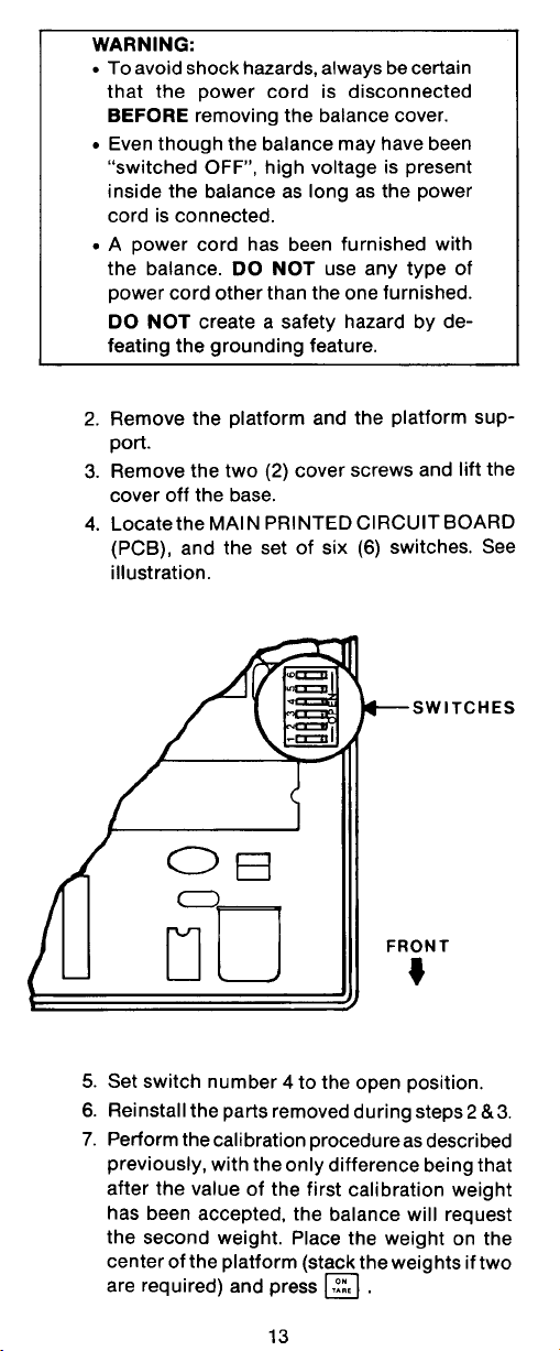
OPERATION ...................................................................................................... 14
Switch Functions......................................................................................... 1 4
Symbols Used for Operation of the Balance .............................................. 15
Navigating the Menus ................................................................................. 16
Operational Guide/Index ............................................................................. 17
Turning the Balance On.............................................................................. 18
Display Indications ...................................................................................... 19
Stabilization................................................................................................. 19
Moveable FineRange
Weighing ..................................................................................................... 20
Zero/Tare .................................................................................................... 20
Auto Tare .................................................................................................... 20
Percent Weighing ........................................................................................ 21
Parts Counting ............................................................................................ 2 2
Check Weighing .......................................................................................... 23
Animal Weighing ......................................................................................... 24
Fill Guide ..................................................................................................... 25
Reference Weight ................................................................................... 25
TM
(Models GT410D and GT4100D) ......................... 19
3

Reference Number .................................................................................. 2 6
High Point.................................................................................................... 26
Printing Data ............................................................................................... 27
Time and Date......................................................................................... 27
List ........................................................................................................... 28
Span Calibration Printout ........................................................................ 29
Linearity Calibration Printout ................................................................... 29
Calibration Test Printout.......................................................................... 29
Statistics Printout .................................................................................... 30
Sampling .................................................................................................. 30
Percent Weighing .................................................................................... 31
Parts Counting ......................................................................................... 31
Check Weighing ...................................................................................... 32
FillGuideTM................................................................................................ 32
MENUS .............................................................................................................. 33
MENU LOCK-OUT PROTECTION .................................................................... 34
TYPE APPROVED BALANCE SEALING .......................................................... 36
CALIBRATION MENU ........................................................................................ 36
Calibration Menu Protection ....................................................................... 36
Calaibration Masses ................................................................................... 36
Span Calibration ......................................................................................... 37
Linearity Calibration ................................................................................... 3 7
User Calibration .......................................................................................... 38
Cal Test....................................................................................................... 38
USER MENU...................................................................................................... 39
User Menu Protection ................................................................................. 39
Reset........................................................................................................... 40
Averaging Level .......................................................................................... 40
Stability Range ............................................................................................ 41
Auto-Zero .................................................................................................... 41
Beep Function ............................................................................................. 42
Exiting User Menu ....................................................................................... 4 2
4

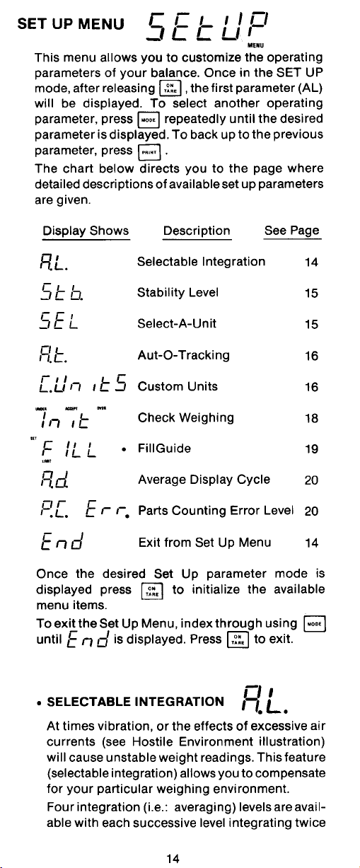
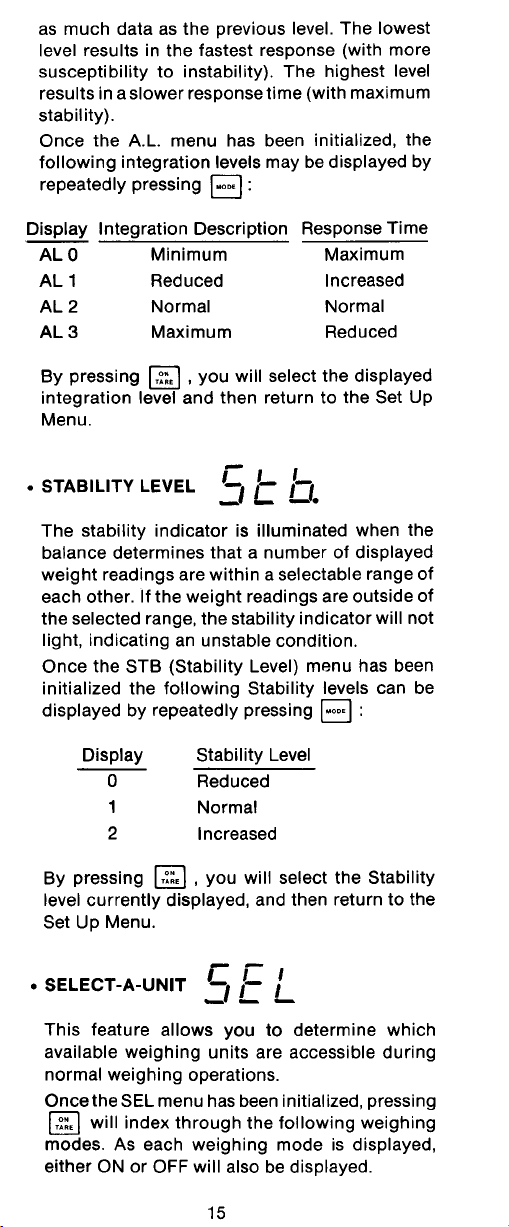
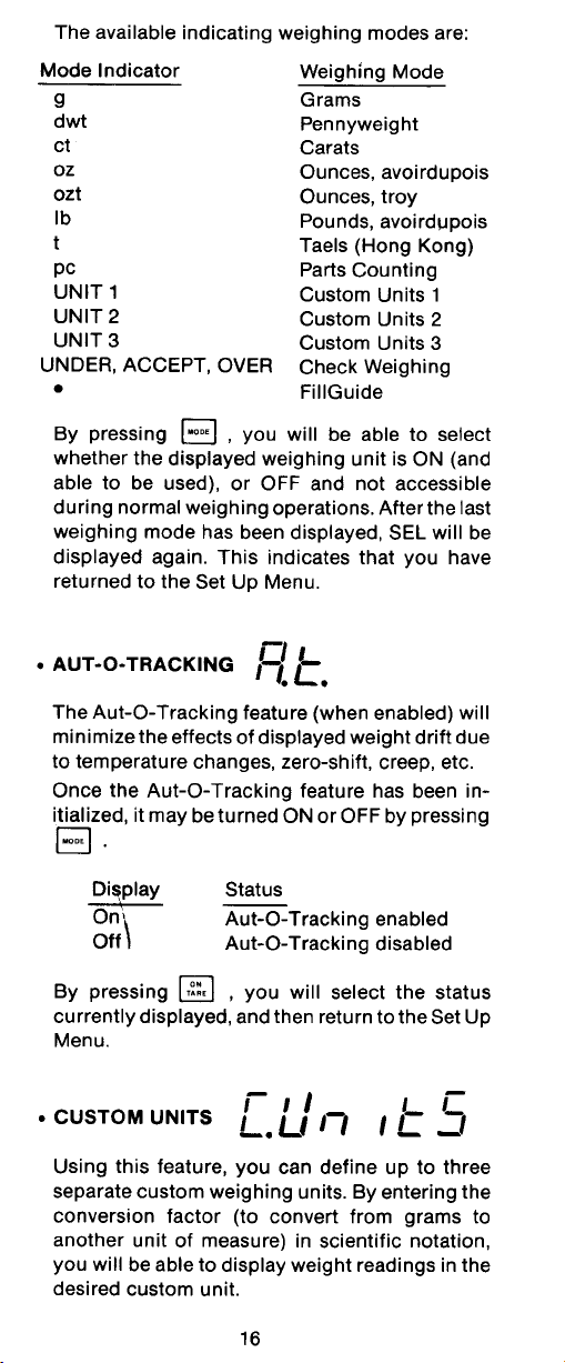
SETUP MENU.................................................................................................... 42
Setup Menu Protection ............................................................................... 44
Reset........................................................................................................... 44
Type Approved/LFT .................................................................................... 45
Unit Selection .............................................................................................. 45
Functions ..................................................................................................... 4 6
Statistics...................................................................................................... 47
Net............................................................................................................... 48
Auto Tare .................................................................................................... 48
Custom Unit or Volume Selection............................................................... 49
Operating Procedure ............................................................................... 50
Good Laboratory Practices......................................................................... 51
Parts Counting Error ................................................................................... 51
Check Weighing Options ............................................................................ 51
Sample Displays ......................................................................................... 53
Animal Weighing Options ........................................................................... 54
Fill Option .................................................................................................... 54
Time ............................................................................................................ 56
Date............................................................................................................. 57
Lockswitch................................................................................................... 58
List............................................................................................................... 59
Exit Setup Menu ......................................................................................... 59
PRINT MENU ..................................................................................................... 60
Print Menu Protection ................................................................................. 6 0
Reset........................................................................................................... 61
Communication ........................................................................................... 61
Baud Rate ............................................................................................... 62
Data Bits .................................................................................................. 62
Parity ....................................................................................................... 62
Stop Bits .................................................................................................. 63
Good Laboratory Practices (GLP) .............................................................. 63
Print Options ............................................................................................... 6 4
Auto Print Feature ................................................................................... 64
5

Initialize.................................................................................................... 64
Print Stable Data Only............................................................................. 66
Print Numeric Data Only ......................................................................... 66
Time......................................................................................................... 66
Date ......................................................................................................... 67
Reference ................................................................................................ 67
Difference ................................................................................................ 67
List ........................................................................................................... 68
CARE AND MAINTENANCE ............................................................................. 69
TROUBLESHOOTING ....................................................................................... 69
Error Codes List .......................................................................................... 70
SERVICE INFORMATION ................................................................................. 72
REPLACEMENT PARTS ................................................................................... 72
ACCESSORIES ................................................................................................. 72
SPECIFICATIONS ............................................................................................. 73
LIMITED WARRANTY ....................................................................................... 75
6

INTRODUCTION
INTRODUCTIONINTRODUCTION
INTRODUCTION
INTRODUCTIONINTRODUCTION
This manual covers Installation, Operation and Troubleshooting for the Ohaus
Precision Advanced Series of Electronic balances, Models GT210, GT400, GT410,
GT2100, GT4000, GT4100, and GT8000. Suffixes after the basic model number are:
D = Moveable FineRangeTM, T=Tower Mount and V=Non Type Approved. Models with
an E suffix = Type Approved with CE conformance and bear official markings (Max,
Min, Class, etc.) on a serial number plate located on the side of the balance. To ensure
proper operation of the balance, please read this manual completely.
DESCRIPTIONDESCRIPTION
DESCRIPTION
DESCRIPTIONDESCRIPTION
The Ohaus Precision Advanced GT Series balances are precision weighing instruments, designed to be versatile, accurate, easy to operate and will provide years of
service with virtually no maintenance. The Precision Advanced series is constructed
using a die-cast aluminum base finished with a durable corrosion resistant epoxy
powder paint. It contains solid-state precision electronics PC boards, and a seven and
a half, 0.45 inch digit, Vacuum Fluorescent display. Each balance operates through
a series of menus which enhances operation. A built in lockswitch prevents preset
settings from being changed. To prevent measurements from being affected by air
currents, a Draft Shield is mounted to the balance and is standard with Models GT210,
GT410 and GT410D.
FEATURES
Precision Advanced balances contain four main display menus which enable you to
calibrate and configure the balance for specific operating requirements.
MENU MENU
•
MENU When switch is pressed and released with MENU displayed, allows
MENU MENU
entry into other menus.
CALIBRATIONCALIBRATION
•
CALIBRATION Menu - Allows the balance to be calibrated by using either Span
CALIBRATIONCALIBRATION
or Linearity calibration methods. A Test function is used to verify the last
calibration.
USERUSER
•
USER Menu - Allows the balance to be set for environmental conditions. Reset,
USERUSER
averaging level, stability range, auto-zero and beep (sound) functions can be set.
SETUPSETUP
•
SETUP Menu - Allows the balance to be customized for specific weighing
SETUPSETUP
functions.
PRINTPRINT
•
PRINT Menu - Allows the selection of parameters under which the balance will
PRINTPRINT
interface to a computer or a printer.
Each of these menus contain selectable parameters which can be entered via the front
panel switches. Storing of the parameters is accomplished by selecting
completion of all selections in a particular menu. For a detailed description of each
feature, refer to the individual menus in this manual.
7
EndEnd
End
EndEnd
at the

INSTALLATION
UNPACKINGUNPACKING
UNPACKING
UNPACKINGUNPACKING
Your Precision Advanced balance was shipped with the following items:
• Platform
• Platform Support
• Power Cord
• Below Balance Weighing Hook
• Draft Shield included with Models: GT210, GT410 and GT410D
• Instruction Manual
• Warranty Card
• In-Service Cover
• Sealing Kit (Type Approved/Legal for Trade)
It is recommended to save the carton and packing material for storing, transporting the
balance or returning it for service.
INSTALLATIONINSTALLATION
INSTALLATION
INSTALLATIONINSTALLATION
EnvironmentEnvironment
Environment
EnvironmentEnvironment
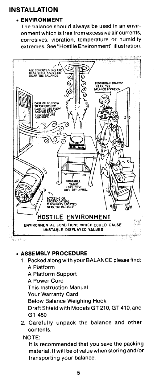
The balance should always be used in an environment which is free from excessive
air currents, corrosives, vibration, and temperature or humidity extremes. These
factors will affect displayed weight readings.
DO NOTDO NOT
DO NOT install the balance:
DO NOTDO NOT
• Next to open windows or doors causing drafts or rapid temperature changes.
• Near air conditioning or heat vents.
• Near vibrating, rotating or reciprocating equipment.
• Near magnetic fields or equipment that
generates magnetic fields.
• On an unlevel work surface.
Below Balance HookBelow Balance Hook
Below Balance Hook
Below Balance HookBelow Balance Hook
A common application for this item is for
determination of density or specific gravity.
Mount the balance on a suitable surface
which allows below balance weighing. If the
below balance hook will be used, it may be
installed in the bottom of the balance. Remove the protective plug at the bottom of
the balance and screw the hook into the
threaded hole in the Platform Support which
is visible through the access hole in the
bottom of the balance.
8
PLATE
BELOW BALANCE HOOK

Leveling the BalanceLeveling the Balance
Leveling the Balance
Leveling the BalanceLeveling the Balance
The balance is equipped with a level indicator
located at the rear of the balance and two
adjustable leveling feet. The leveling feet are
located under the front of the balance. Adjust
the leveling feet until the bubble appears in the
center circle of the indicator.
NOTENOTE
NOTE: A level indicator and leveling feet are
NOTENOTE
not included on Models GT400, GT4000 and
GT8000.
Power RequirementsPower Requirements
Power Requirements
Power RequirementsPower Requirements
WARNING
To avoid shock hazards, always beTo avoid shock hazards, always be
•
To avoid shock hazards, always be
To avoid shock hazards, always beTo avoid shock hazards, always be
certain that the power cord is dis-certain that the power cord is dis-
certain that the power cord is dis-
certain that the power cord is dis-certain that the power cord is disconnected BEFORE removing theconnected BEFORE removing the
connected BEFORE removing the
connected BEFORE removing theconnected BEFORE removing the
balance cover.balance cover.
balance cover.
balance cover.balance cover.
Even though the balance may haveEven though the balance may have
•
Even though the balance may have
Even though the balance may haveEven though the balance may have
been switched OFF, high voltage isbeen switched OFF, high voltage is
been switched OFF, high voltage is
been switched OFF, high voltage isbeen switched OFF, high voltage is
present inside the balance as longpresent inside the balance as long
present inside the balance as long
present inside the balance as longpresent inside the balance as long
as the power cord is connected.as the power cord is connected.
as the power cord is connected.
as the power cord is connected.as the power cord is connected.
INSTALLATION
LEVEL INDICATOR
A power cord has been furnishedA power cord has been furnished
•
A power cord has been furnished
A power cord has been furnishedA power cord has been furnished
with the balance. DO NOT use anywith the balance. DO NOT use any
with the balance. DO NOT use any
with the balance. DO NOT use anywith the balance. DO NOT use any
other type of power cord other thanother type of power cord other than
other type of power cord other than
other type of power cord other thanother type of power cord other than
the one furnished.the one furnished.
the one furnished.
the one furnished.the one furnished.
DO NOT create a safety hazard byDO NOT create a safety hazard by
DO NOT create a safety hazard by
DO NOT create a safety hazard byDO NOT create a safety hazard by
defeating the grounding feature.defeating the grounding feature.
defeating the grounding feature.
defeating the grounding feature.defeating the grounding feature.
Voltage SettingVoltage Setting
Voltage Setting
Voltage SettingVoltage Setting
The balance can be damaged if operated
at an incorrect line voltage. If, for any
reason the balance
operate at your particular line voltage, it
may be checked in the following manner:
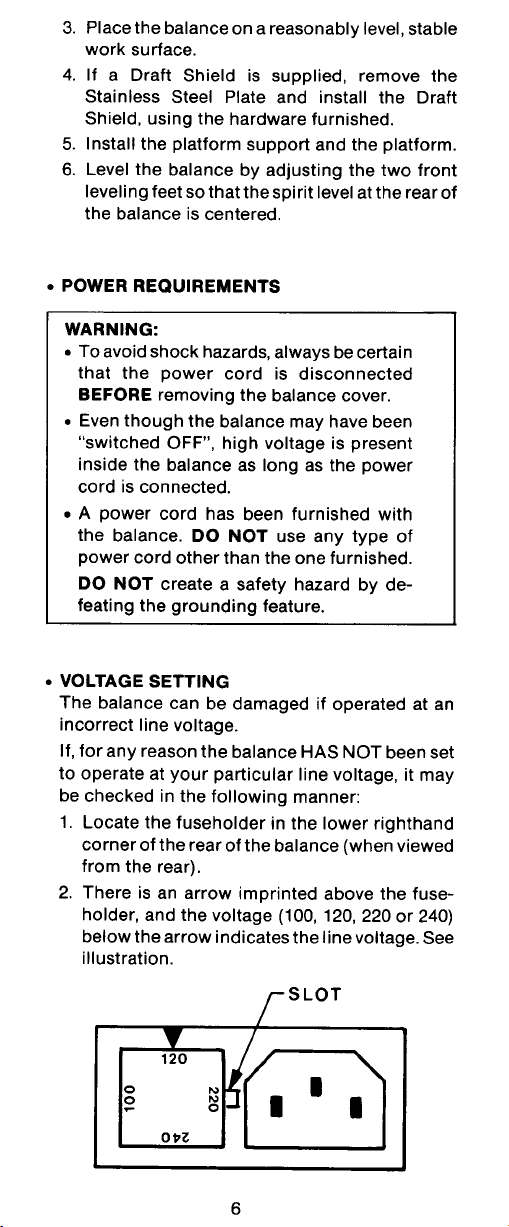
1. Locate the fuse holder in the lower
right-hand corner of the balance
(when viewed from the rear).
2. There is an arrow imprinted above
the fuse holder and the voltage (100,
120, 220 or 240) below the arrow
indicates the line voltage. See illustration.
HAS NOTHAS NOT
HAS NOT been set to
HAS NOTHAS NOT
SLOT
9

INSTALLATION
3. If you wish to change the line voltage setting, remove the power cord and pry
the fuse holder loose by inserting a small screwdriver blade in the slot. Remove
the fuse holder and rotate it to the proper position with the correct line voltage
lining up with the arrow. If neccessary, install the correct fuse for the required
line voltage. (See Replacement Parts List for fuse rating).
4. Insert the fuse holder.
Draft Shield (Models GT210, GT410Draft Shield (Models GT210, GT410
Draft Shield (Models GT210, GT410
Draft Shield (Models GT210, GT410Draft Shield (Models GT210, GT410
and GT 410D)and GT 410D)
and GT 410D)
and GT 410D)and GT 410D)
To install the Draft Shield:
1. Remove the two existing screws and
washers located on top of the balance.
2. Position the Draft Shield on top of the
balance as shown.
3. Insert the two screws, with washers
(supplied with the Draft Shield) though
the holes in the Draft Shield into the
balance. Tighten both screws securely.
DRAFT SHIELD
Platform and Platform SupportPlatform and Platform Support
Platform and Platform Support
Platform and Platform SupportPlatform and Platform Support
Insert the Platform Support into the hole
in the weighing mechanism as shown in
the illustration.
Place the Platform on the Platform Support making sure the Platform is properly
centered.
Model GT8000T Tower Assembly InstallationModel GT8000T Tower Assembly Installation
Model GT8000T Tower Assembly Installation
Model GT8000T Tower Assembly InstallationModel GT8000T Tower Assembly Installation
Remove the four (4) flat head screws from the mounting holes at the lower left (
when viewing the rear of the balance), and set them aside. Install the Tower
Assembly on the mounting holes using the screws. The Tower Display unit may
be tilted to the desired viewing angle. If the viewing angle is not going to be
changed, tighten the Hex Socket set screw at the lower left (when viewing the rear
of the Display Unit). The increased tension will prevent the Display Unit from
accidentally tilting.
10
PLATFORM
PLATFORM
SUPPORT

INSTALLATION
RS232 INTERFACERS232 INTERFACE
RS232 INTERFACE
RS232 INTERFACERS232 INTERFACE
Precision Advanced balances are equipped with a bi-directional RS232 compatible
interface for communication with printers and computers. When the balance is
connected directly to a printer, displayed data can be output at any time by simply
pressing PRINT, or by using the Auto Print feature.
Connecting the balance to a computer enables you to operate the balance from the
computer, as well as receive data such as displayed weight, weighing mode,
stability status, etc.
The following sections describe the hardware and software provided with the
balance.
HardwareHardware
Hardware
HardwareHardware
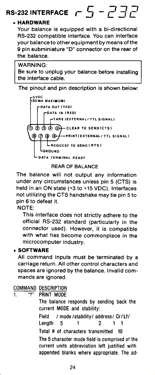
On the rear of the balance, a 9-pin subminiature “D” connector is provided for
interfacing to other devices. The pinout
and pin connections are shown in the
adjacent illustration.
The balance will not output any data
unless pin 5 (CTS) is held in an ON state
(+3 to +15 VDC). Interfaces not utilizing
the CTS handshake may tie pin 5 to pin 6
to defeat it.
Output FormatsOutput Formats
Output Formats
Output FormatsOutput Formats
Data output can be initiated in one of three
ways: 1) By pressing PRINT; 2) Using the
Auto Print feature; 3) Sending a print
command (“P”) from a computer.
The output format is illustrated in the
RS232 command table which follows.
RS232 CommandsRS232 Commands
RS232 Commands
RS232 CommandsRS232 Commands
All communication is accomplished using
standard ASCII format. Only the characters shown in the following table are acknowledged by the balance. Any other
commands, control characters or spaces
are ignored. Commands sent to the
balance must be terminated with a carriage return (CR) or carriage return-line
line feed (CRLF). For example, a tare
command should appear as shown in the
adjacent diagram. Data output by the
balance is always terminated with a carriage return - line feed (CRLF).
TARE *
PRINT *
1 5VDC (5 mA max.)
2 Data Out (TXD)
3 Data In (RXD)
4* Tare (External signal)
5 Clear To Send (CTS)
6 Data Terminal Ready (DTR)
7 Ground
8 Request To Send (RTS)
9* Print (External signal)
* External PRINT and/or TARE
switches may be installed as shown
in the diagram. Momentary contact
switches must be used.
11

INSTALLATION
RS232 COMMAND TABLERS232 COMMAND TABLE
RS232 COMMAND TABLE
RS232 COMMAND TABLERS232 COMMAND TABLE
CommandCommand
Command
CommandCommand
CharacterCharacter
Character
CharacterCharacter
??
? Print current mode
??
nnnAnnnA
nnnA Set Auto Print feature to “nnn”
nnnAnnnA
CC
C Begin span calibration
CC
xDxD
xD Set 1 second print delay (set x = 0 for OFF, or x = 1 for ON)
xDxD
DescriptionDescription
Description
DescriptionDescription
(see table).
Field: Mode Stab CR LF
Length: 5 1 1 1
Grams
Pennyweight
Carats
Avoidupois ounces
Troy ounces
Grains
Taels
nnn = 0 Turns feature OFF
nnn = S Output on stability
nnn = C Output is continuous
nnn = 1-256 Sets Auto Print
blank if stable
“ ? ” if unstable
Momme
Pounds
Pounds:ounces
Custom unit
Parts counting
Percent weighing
Error
Interval
EE
E Exit parts counting or percent weighing
EE
xx
II
x
I Set Averaging Level to “x”,
xx
II
LL
L Begin linearity calibration
LL
MM
M Same effect as pressing mode button
MM
xMxM
xM Places balance in mode “x”,
xMxM
where x = 0 to 3 (see table).
where x = 1 to 13 (see table).
If unit or mode is not already
enabled, command will be ignored.
12
0 = minimum level
1=
2=
3 = maximum level
1 = grams
2 = pennyweight
3 = carats
4 = avoidupois ounces
5 = troy ounces
6 = grains
7 = taels
8 = momme
9 = pounds
10 = pounds:ounces
11 = custom unit
12 = parts counting
13 = percent weighing

INSTALLATION
CommandCommand
Command
CommandCommand
CharacterCharacter
Character
CharacterCharacter
PP
P Print display data
PP
xSxS
xS Set stable data only printing (set x = 0 for OFF, or x = 1 for ON).
xSxS
TT
T Same effect as pressing rezero button
TT
VV
V Print EPROM version
VV
DescriptionDescription
Description
DescriptionDescription
When “numeric only” display
data is selected for output in
the RS232 menu, the Mode
field is not output.
Field: Weight Mode Stab CR LF
Length: 9 1 5 1 1 1
Displayed weight sent right justified
w/lead zero blanking.
Nine characters include:
decimal point (1)
weight (7 max))
polarity (1): blank if positive
Field: Model # EPROM # CR LF
Length: 7 15 1 1
Same as ?
command
“ - ” if negative
Balance Model
xZxZ
xZ Set Auto Zero to “x”,
xZxZ
x%x%
x% Downloads reference weight “x” for percent mode. “x” must be in grams.
x%x%
x#x#
x# Downloads average piece weight “x” for parts counting mode. “x” must be in
x#x#
Esc LEsc L
Esc L Prints listing of Setup and Print menu settings.
Esc LEsc L
Esc REsc R
Esc R Resets Setup and Print menus to factory defaults.
Esc REsc R
Esc SEsc S
Esc S Save current settings.
Esc SEsc S
where x = 0 to 3 (see table).
Command is ignored if percent mode is disabled. If percent mode is enabled,
balance will automatically switch to percent mode display.
grams. Command is ignored if parts counting mode is disabled. If parts counting
is enabled, balance will automatically switch to parts count display.
CAUTION: This will reset RS232 configuration.
"98101-XX Sr*XX.X"
0 = OFF
1 = .5 d
2=1 d
3=3 d
13

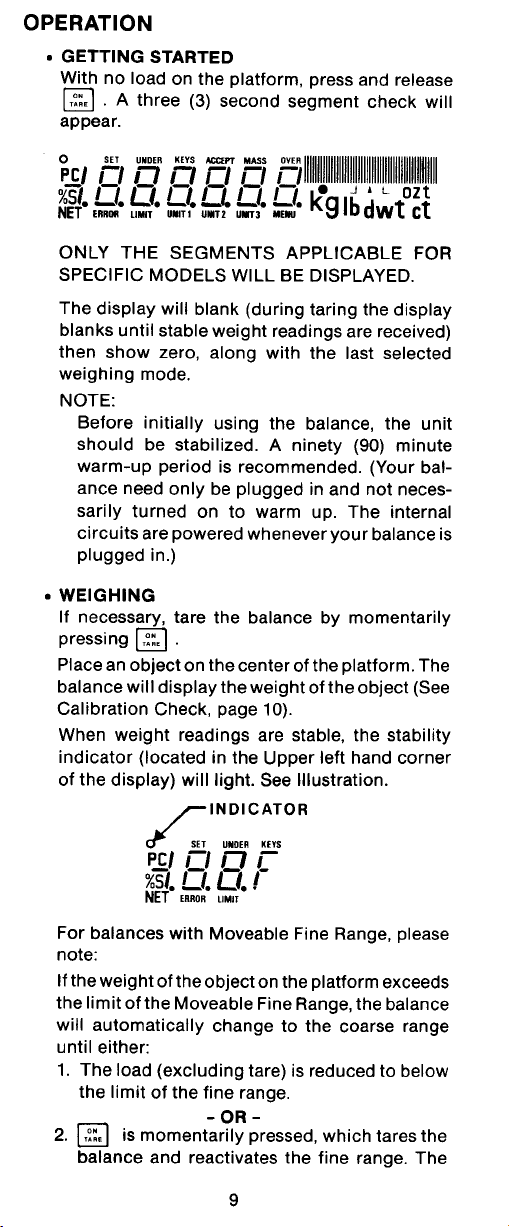
OPERATION
OPERATIONOPERATION
OPERATION
OPERATIONOPERATION
Switch FunctionsSwitch Functions
Switch Functions
Switch FunctionsSwitch Functions
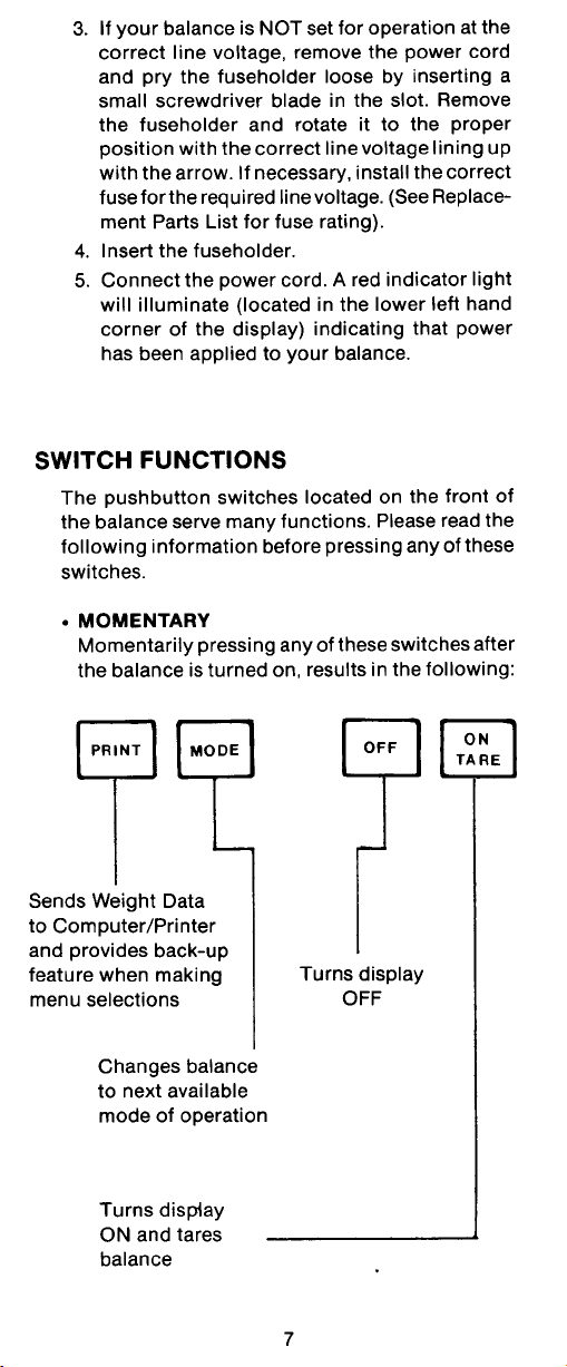
The pushbutton switches located on the front of the balance serve many functions.
please read the following information before pressing any of these switches.
Pressing any of these switches after the balance is turned on results in the following:
Sends weight data, statistical data, GLP data to computer/printer. In menus, allows returning to a previous
menu step.
Selects weighing units functions or options. In menus,
changes to next step or value.
When the balance is first turned on and it completes its checks, and is calibrated, it
can be used to weigh or tare materials without setting the menus.
There are many features and functions in the GT Balance, and if you do not address
all of the features, the balance has built-in default settings shown on each menu page.
Before using the balance, carefully review the Symbols Used for Operation of the
Balance shown on page 15, Navigating the Menus on page 16 and Operational Guide/
Index on page 17.
Please read the entire manual as there are many features which can be enabled. The
balance is shipped from the factory ready to operate with default settings as shown
in the menus.
The balance is a high precision instrument and will give you years of service if kept
clean and handled carefully. If you have any problems operating the instrument or
require additional information, please feel free to contact our Product Service
Department at (800) 526-0659.
Turns display OFF.
Turns display ON and ReZeros/Tares the balance. In
menus, accepts chosen parameter.
14

Symbols Used for Operation of the BalanceSymbols Used for Operation of the Balance
Symbols Used for Operation of the Balance
Symbols Used for Operation of the BalanceSymbols Used for Operation of the Balance
This instruction manual uses certain symbols to explain various operational procedures and actions that occur. Examples of the symbols used are shown as follows:
Pushbutton SwitchesPushbutton Switches
Pushbutton Switches:
Pushbutton SwitchesPushbutton Switches
=
=
Display Area Display Area
Display Area:
Display Area Display Area
NORMAL PRESS AND RELEASENORMAL PRESS AND RELEASE
NORMAL PRESS AND RELEASE
NORMAL PRESS AND RELEASENORMAL PRESS AND RELEASE
MULTIPLE PRESSMULTIPLE PRESS
MULTIPLE PRESS
MULTIPLE PRESSMULTIPLE PRESS
PRESS AND HOLD FOR DESIRED DISPLAYPRESS AND HOLD FOR DESIRED DISPLAY
=
PRESS AND HOLD FOR DESIRED DISPLAY
PRESS AND HOLD FOR DESIRED DISPLAYPRESS AND HOLD FOR DESIRED DISPLAY
DISPLAY AREA - AS A RESULT OF USER ACTIONDISPLAY AREA - AS A RESULT OF USER ACTION
DISPLAY AREA - AS A RESULT OF USER ACTION
DISPLAY AREA - AS A RESULT OF USER ACTIONDISPLAY AREA - AS A RESULT OF USER ACTION
DISPLAY AREA -SWITCHES BACK AND FORTHDISPLAY AREA -SWITCHES BACK AND FORTH
DISPLAY AREA -SWITCHES BACK AND FORTH
DISPLAY AREA -SWITCHES BACK AND FORTHDISPLAY AREA -SWITCHES BACK AND FORTH
DISPLAY AREA - AUTO CHANGE OCCURSDISPLAY AREA - AUTO CHANGE OCCURS
DISPLAY AREA - AUTO CHANGE OCCURS
DISPLAY AREA - AUTO CHANGE OCCURSDISPLAY AREA - AUTO CHANGE OCCURS
15

OPERATION
Navigating the MenusNavigating the Menus
Navigating the Menus
Navigating the MenusNavigating the Menus
There are
CALIBRATION USER SETUP PRINT
To enter the menusTo enter the menus
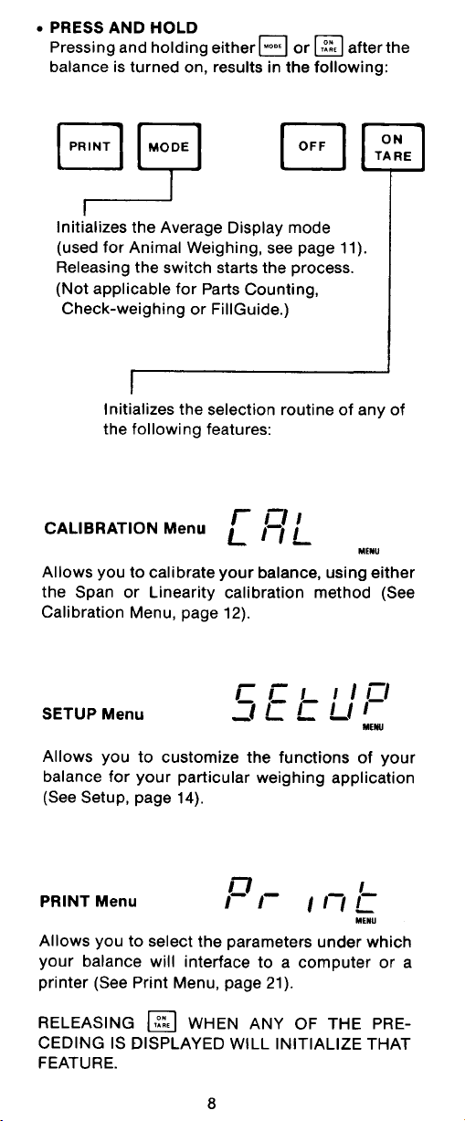
To enter the menus, the button is pressed and held until MENU is displayed.
To enter the menusTo enter the menus
When released, CAL is displayed which is the Calibration menu.
When in the menusWhen in the menus
When in the menus, repeated pressing of
When in the menusWhen in the menus
menus. CALIBRATION USER SETUP PRINT END
Each menu contains selections (submenus) which can be set for specific operations.
The button is used to advance though the submenu selections.
four menusfour menus
four menus used in the balance:
four menusfour menus
advances through the
MENU
The
button enters or accepts the submenu selection and returns to the
beginning of the submenu selection.
The button is used to backup in the submenu if a change is desired.
The following sample illustrates the
END USEREND USER
END USER
END USEREND USER
ONON
ON
ONON
BEEPBEEP
BEEP
BEEPBEEP
<
<
<
OFFOFF
OFF
OFFOFF
ONON
ON
ONON
AUTO-ZEROAUTO-ZERO
<
AUTO-ZERO
AUTO-ZEROAUTO-ZERO
<
<
OFFOFF
OFF
OFFOFF
USERUSER
USER
USERUSER
RESETRESET
RESET
RESETRESET
STABILITYSTABILITY
STABILITY
STABILITYSTABILITY
USER menu USER menu
USER menu and submenu items
USER menu USER menu
NOTE:NOTE:
NOTE:
NOTE:NOTE:
>
YESYES
YES
YESYES
ALAL
AL
ALAL
<
<
NONO
NO
NONO
00
0
00
>
<
<
11
1
11
<
22
2
22
<
33
3
33
Each menu is constructed
in the form of a loop. Advancing from one submenu item to the next by
using the
will eventually return to
the beginning of the
>
OFFOFF
OFF
OFFOFF
<
.5d.5d
.5d
.5d.5d
<
menu. .
<
1d1d
1d
1d1d
<
3d3d
3d
3d3d
RULES: UseRULES: Use
RULES: Use
RULES: UseRULES: Use
button to advance.button to advance.
button to advance.
button to advance.button to advance.
button
Use Use
Use
Use Use
Use Use
Use
Use Use
After selections are made, always exit menus through END After selections are made, always exit menus through END
After selections are made, always exit menus through END
After selections are made, always exit menus through END After selections are made, always exit menus through END
store settings. store settings.
store settings.
store settings. store settings.
button to enter or accept submenu. button to enter or accept submenu.
button to enter or accept submenu.
button to enter or accept submenu. button to enter or accept submenu.
button to backup.button to backup.
button to backup.
button to backup.button to backup.
16
MENU MENU
MENU
MENU MENU
to to
to
to to

OPERATION
Operational Guide/IndexOperational Guide/Index
Operational Guide/Index
Operational Guide/IndexOperational Guide/Index
The Operational Guide/Index lists the pages for all balance operations and options.
After settings are made, exit menus to save settings.
FUNCTION FUNCTION
FUNCTION
FUNCTION FUNCTION
1.1.
Turning the Balance ONTurning the Balance ON
1.
Turning the Balance ON
1.1.
Turning the Balance ONTurning the Balance ON
2.2.
Weighing (grams)Weighing (grams)
2.
Weighing (grams)
2.2.
Weighing (grams)Weighing (grams)
3.3.
Zero/TaringZero/Taring
3.
Zero/Taring
3.3.
Zero/TaringZero/Taring
4.4.
Auto TareAuto Tare
4.
Auto Tare
4.4.
Auto TareAuto Tare
5.5.
ListList
5.
List
5.5.
ListList
6.6.
Printing DataPrinting Data
6.
Printing Data
6.6.
Printing DataPrinting Data
7.7.
Menu LockoutMenu Lockout
7.
Menu Lockout
7.7.
Menu LockoutMenu Lockout
8.8.
CalibrationCalibration
8.
Calibration
8.8.
CalibrationCalibration
9.9.
Percent WeighingPercent Weighing
9.
Percent Weighing
9.9.
Percent WeighingPercent Weighing
10.10.
Parts CountingParts Counting
10.
Parts Counting
10.10.
Parts CountingParts Counting
11.11.
Check weighingCheck weighing
11.
Check weighing
11.11.
Check weighingCheck weighing
12.12.
Animal WeighingAnimal Weighing
12.
Animal Weighing
12.12.
Animal WeighingAnimal Weighing
13.13.
Fill GuideFill Guide
13.
Fill Guide
13.13.
Fill GuideFill Guide
14.14.
High PointHigh Point
14.
High Point
14.14.
High PointHigh Point
15.15.
Custom UnitsCustom Units
15.
Custom Units
15.15.
Custom UnitsCustom Units
16.16.
Changing UnitsChanging Units
16.
Changing Units
16.16.
Changing UnitsChanging Units
17.17.
StatisticsStatistics
17.
Statistics
17.17.
StatisticsStatistics
18.18.
NetNet
18.
18.18.
19.19.
19.
19.19.
20.20.
20.
20.20.
21.21.
21.
21.21.
22.22.
22.
22.22.
23.23.
23.
23.23.
24.24.
24.
24.24.
25.25.
25.
25.25.
26.26.
26.
26.26.
27.27.
27.
27.27.
28.28.
28.
28.28.
29.29.
29.
29.29.
30.30.
30.
30.30.
31.31.
31.
31.31.
/Gross Weighing/Gross Weighing
Net
/Gross Weighing
NetNet
/Gross Weighing/Gross Weighing
Legal for TradeLegal for Trade
Legal for Trade
Legal for TradeLegal for Trade
GLPGLP
GLP
GLPGLP
TimeTime
Time
TimeTime
DateDate
Date
DateDate
LockswitchLockswitch
Lockswitch
LockswitchLockswitch
Averaging LevelAveraging Level
Averaging Level
Averaging LevelAveraging Level
StabilityStability
Stability
StabilityStability
Auto ZeroAuto Zero
Auto Zero
Auto ZeroAuto Zero
Beep FunctionBeep Function
Beep Function
Beep FunctionBeep Function
Reset UserReset User
Reset User
Reset UserReset User
Reset SetupReset Setup
Reset Setup
Reset SetupReset Setup
Reset PrintReset Print
Reset Print
Reset PrintReset Print
CommunicationsCommunications
Communications
CommunicationsCommunications
TO OPERATETO OPERATE
TO OPERATE
TO OPERATETO OPERATE
( (
(See pages) (See pages)
( (
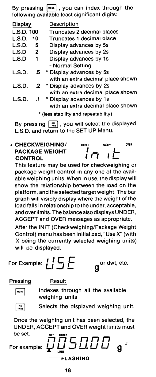
1818
18
1818
2020
20
2020
2020
20
2020
2020
20
2020
2828
28
2828
27 to 3227 to 32
27 to 32
27 to 3227 to 32
3434
34
3434
36 to 3936 to 39
36 to 39
36 to 3936 to 39
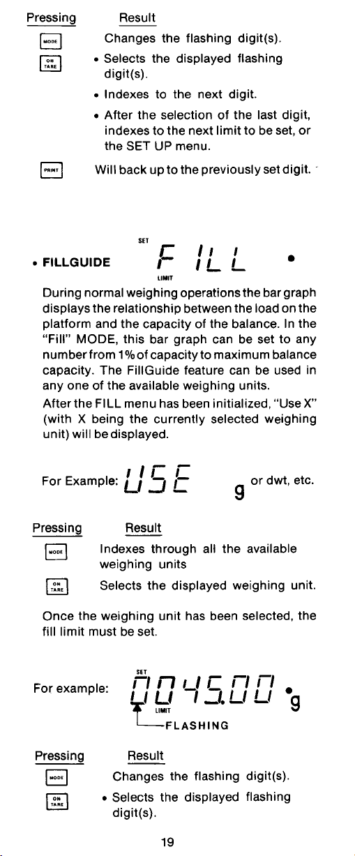
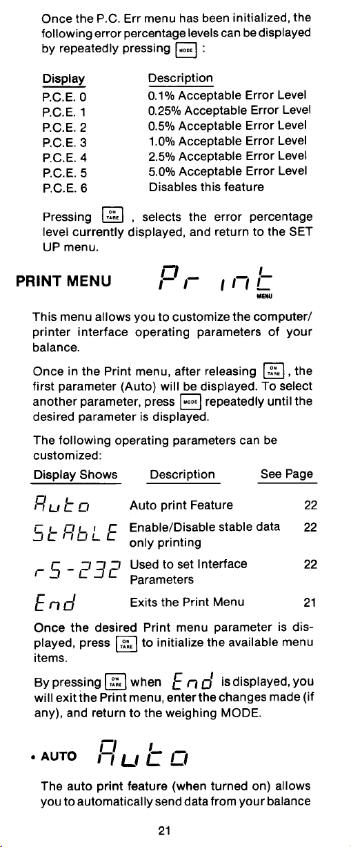
2121
21
2121
2222
22
2222
2323
23
2323
2424
24
2424
2525
25
2525
2626
26
2626
5050
50
5050
--------
----
--------
--------
----
--------
--------
----
--------
--------
----
--------
--------
----
--------
--------
----
--------
--------
----
--------
--------
----
--------
--------
----
--------
--------
----
--------
--------
----
--------
--------
----
--------
--------
----
--------
--------
----
--------
--------
----
--------
--------
----
--------
SETUPSETUP
SETUP
SETUPSETUP
--------
----
--------
--------
----
--------
--------
----
--------
--------
----
-------59, 6859, 68
59, 68
59, 6859, 68
61 to 6861 to 68
61 to 68
61 to 6861 to 68
--------
----
--------
--------
----
-------46, 6746, 67
46, 67
46, 6746, 67
46, 51, 6746, 51, 67
46, 51, 67
46, 51, 6746, 51, 67
46, 52, 53, 6746, 52, 53, 67
46, 52, 53, 67
46, 52, 53, 6746, 52, 53, 67
46, 5446, 54
46, 54
46, 5446, 54
46, 54, 6746, 54, 67
46, 54, 67
46, 54, 6746, 54, 67
4646
46
4646
4949
49
4949
4545
45
4545
4545
45
4545
4848
48
4848
4545
45
4545
51, 6351, 63
51, 63
51, 6351, 63
56, 6656, 66
56, 66
56, 6656, 66
57, 6757, 67
57, 67
57, 6757, 67
5858
58
5858
4040
40
4040
4141
41
4141
4141
41
4141
4242
42
4242
4040
40
4040
4444
44
4444
6161
61
6161
61 to 6361 to 63
61 to 63
61 to 6361 to 63
17

OPERATION
Turning the Balance ONTurning the Balance ON
Turning the Balance ON
Turning the Balance ONTurning the Balance ON
1. With no load on the platform, connect the power cord to a suitable power
source. The balance signals one long beep to indicate power has been applied.
2.
NOTENOTE
NOTE: The display check countdown appears only in the first 60 seconds after
NOTENOTE
plugging it in and only if the balance is turned on and only when the balance has
been previously set with Type Approved/Legal for Trade set on.
•
•
•
•
•
18

Display IndicationsDisplay Indications
Display Indications
Display IndicationsDisplay Indications
The following table describes each of the display indicators.
DISPLAY INDICATORSDISPLAY INDICATORS
DISPLAY INDICATORS
DISPLAY INDICATORSDISPLAY INDICATORS
StabilizationStabilization
Stabilization
StabilizationStabilization
OPERATION
Before initially using the balance, allow time for it to adjust to its new environment. The
balance only requires to be plugged in to warm up. Recommended warm up period
is twenty (20) minutes. The internal circuits of the balance are powered whenever
it is plugged into a power source.
TMTM
TM
Moveable FineRangeMoveable FineRange
Moveable FineRange
Moveable FineRangeMoveable FineRange
Models GT410D and GT4100D both contain a Moveable FineRangeTM feature. When
the weight of the object on the platform exceeds the capacity limit of the Moveable
FineRangeTM, the balance will automatically change to the coarse range until either:
1. The load is reduced to below the capacity limit of the fine range.
2.
tares the balance and recalls the fine range. Taring procedure can
be done repeatedly until capacity of the balance is reached.
TMTM
(Models GT410D and GT4100D) (Models GT410D and GT4100D)
(Models GT410D and GT4100D)
(Models GT410D and GT4100D) (Models GT410D and GT4100D)
19

OPERATION
WeighingWeighing
Weighing
WeighingWeighing
NOTENOTE
NOTE: The GT Series balances are shipped with grams only enabled and is labeled
NOTENOTE
in this manner. When the balance is to be used with other Type Approved/Legal
for Trade units of measure, the desired unit must be enabled and the appropriate
label from the card supplied must be attached to the balance
1.
2. Place the object(s) or material to be weighed on the platform.
3. Wait for the stability indicator to appear before reading the weight.
STABILITY INDICATOR
NOTENOTE
NOTE: The capacity guide (bars) indicates the percentage of the current weight to
NOTENOTE
the balance capacity. The example above illustrates a 4000 gram weight, (balance
full capacity 4100 grams).
Zero/TareZero/Tare
Zero/Tare
Zero/TareZero/Tare
When weighing material or objects that must be held in a container, taring stores the
container weight in the balance’s memory, separate from the weight of the material
in the container.
1. Place an empty container on the platform. Its weight is displayed.
NOTENOTE
NOTE: The container must weigh at least 100 times the readability of the balance (ie,
NOTENOTE
GT4K x 0.1 or 10 grams).
2.
indicates zero. The container’s weight is stored in memory.
3. Add material to the container. As material is added, its net weight is displayed.
4. Removing the container and material from the platform will cause the balance
to display the container’s weight as a negative number.
5.
Auto TareAuto Tare
Auto Tare
Auto TareAuto Tare
Auto Tare is
to page 42. Auto Tare is used in an application where taring is done automatically
without touching any controls on the balance. This is indicated by a small arrow in the
display. When this option is set on, each time an object is first placed on the balance
platform, it is automatically tared and two short beeps will sound. When a second
object is placed on the platform along with the first object such as a container, only
the net weight is displayed. The container weight is not shown. After removal of all
material from the platform, the next object placed on the platform is auto tared. The
default setting is off.
to rezero the display.
CAPACITY GUIDE
, the display blanks until stable weight readings are received, then
resets the balance to zero.
enabled onlyenabled only
enabled only
enabled onlyenabled only
when Auto Tare is selected under the Setup menu. Refer
NOTENOTE
NOTE: Auto Tare is disabled for LFT.
NOTENOTE
AUTO TARE INDICATOR
20

OPERATION
Percent WeighingPercent Weighing
Percent Weighing
Percent WeighingPercent Weighing
Percent Weighing is
the Percent Function is selected under the
Setup menu. Refer to page 40. Percent
weighing permits you to place a reference
load on the balance, then view other loads
as a percentage of the reference. The load
you place on the platform as a reference
may be displayed as any percentage you
select from 5% to 100% (in 1% increments). One hundred percent does not
necessarily have to represent the reference load. Subsequent loads, displayed as a
percentage of the reference are limited only by the capacity of the balance. The
default setting is Reference 100%.
To perform percent weighing when in a weighing mode, use the following procedure:
1. .
2. Place an empty container on the pan (if one will be used).
enabled only enabled only
enabled only
enabled only enabled only
when
EXAMPLE EXAMPLE
EXAMPLE
EXAMPLE EXAMPLE
A 10g reference load is set for 20%:
• A subsequent load of 100 g will be
displayed as 200%.
• A subsequent load of 200 g will be
displayed as 400%.
3.
NOTENOTE
NOTE: The reference percentage can be changed to any value from 5 to 100.
NOTENOTE
4.
NOTENOTE
NOTE:
NOTENOTE
command through the RS232 Interface, where x = 5 to 100.
5. When the selected reference value appears on the display, place the
reference load in the container (or directly on the platform if no container is
used).
6. , display indicates the reference load as
the percentage entered. The bar graph indicates the load relative to the
capacity of the balance.
7. Remove the reference load from the balance and replace it with another
load. The second load is displayed as a percentage of the reference.
8. to view alternate display in units.
9. To restart percent weighing at any time,
does not return to a lower number. Instead, it sends Set x%
. This is the current reference percentage.
increments to .
.
10. to exit to a weighing mode.
21

OPERATION
Parts CountingParts Counting
Parts Counting
Parts CountingParts Counting
Parts Counting is
Setup menu. Refer to page 40. In the parts counting mode, the balance displays the
quantity of parts you place on the platform. Since the balance determines the quantity
based on the average weight of a single part, all parts must be reasonably uniform in
weight. The accuracy of parts counting results is determined by the error level entered
in PC Err of the Setup Options submenu. Refer to page 51. The default setting for
PC Err is off.
To perform parts counting when in a weighing mode, use the following procedure:
enabled onlyenabled only
enabled only
enabled onlyenabled only
when the Parts Counting Function is selected in the
1.
2.
to use as a reference for counting. The default for the sample size is 5 parts,
but this can be changed to 10, 20, 30, 40, 50, or 100 parts by
(Larger samples yield more accurate results). Add the required number of
sample pieces to the platform.
3.
4. If Add X is displayed, the sample is too small to provide results within the
selected error level (PC Error of the Setup Options submenu).
NOTENOTE
NOTE: X represents the number of additional parts needed to provide a sufficient
NOTENOTE
sample.
5. Add the required number of parts, then again.
6. To count additional pieces, add them to the platform. The display indicates the
actual number of pieces based on their sample size. Tolerance will be within
whatever was selected under the Parts Counting Error Level.
NOTENOTE
NOTE: If the balance controls are not touched, the sample size is stored in memory.
NOTENOTE
You can continue to use the balance to measure quantities as long as the
samples to be measured are of the same weight.
7.
. The balance requires a sample of the parts
to display the weight of the pieces on the pan.
.
(indicates 5 pieces).
8.
9. To restart parts counting, .
10.
again to display the number of pieces.
, the balance returns to a weighing mode.
22

OPERATION
Check WeighingCheck Weighing
Check Weighing
Check WeighingCheck Weighing
Check Weighing is
the Setup menu. Refer to page 46. Refer to page 52, Check Weighing Options under
the Setup menu to set the Reference Type and Display Type options. In the check
weighing mode, a reference weight can be set into the balance either as a reference
weight on the pan or as a user entered number. The balance display shows either
under, accept or over as each sample is weighed.
reference weight reference weight
If
reference weight was selected under CW Options submenu:
reference weight reference weight
1. With the balance in the weighing mode, .
enabled only enabled only
enabled only
enabled only enabled only
when the Check Weighing Function is selected in
NOTENOTE
NOTE: If
NOTENOTE
10.
11. . to accept the value.
12. Repeat steps 10 and 11and set all digits to the desired value. When the last
reference numberreference number
reference number was selected, go to step 7.
reference numberreference number
2. Place a sample weight on the pan which is considered to be the under limit
for check weighing.
3. .
4. Place a sample weight on the pan which is considered to be the over weight
limit for check weighing.
5. . The display blanks until a stable reading is achieved, then it goes
to either the (Normal, None or Sign) display type previously selected in CW
Options submenu to indicate under, over or acceptacle limits of the objects
being weighed.
6. Check weighing can now be made by removing a sample and placing a new
sample on the pan.
reference numberreference number
If
reference number was selected under the CW Options submenu:
reference numberreference number
7. With the balance in the weighing mode,
8.
9.
digit is entered, display changes to an over value to be entered with the
to return to weighing .
indicates under value with first digit flashing.
until the first digit (under weight) is correctly displayed.
.
first digit flashing
NOTENOTE
NOTE: allows going back.
NOTENOTE
23
.

OPERATION
Check Weighing (Cont.)Check Weighing (Cont.)
Check Weighing (Cont.)
Check Weighing (Cont.)Check Weighing (Cont.)
13. Repeat steps 10 and 11 to set the over value. When the last digit is entered,
the display indicates one of three display modes for check weighing.
14. Check weighing can now be performed by removing a sample and placing a
new sample on the platform.
15. allows other weighing units to be displayed if previously
selected.
Animal WeighingAnimal Weighing
Animal Weighing
Animal WeighingAnimal Weighing
Animal Weighing is
the Setup menu. Refer to page 46. To set options, refer to page 55, Animal Weighing
Options under the Setup Options submenu.
With the balance in a weighing mode, proceed as follows:
enabled only enabled only
enabled only
enabled only enabled only
when Animal Weighing Function is selected under
1.
2. Place the container on the platform.
NOTENOTE
NOTE:
NOTENOTE
3.
4. Place the subject in the container. The balance indicates a countdown to
The balance then displays the actual weight of the subject with flashing unit
indicator and returns to after approximately six sec-
onds. Repeat steps 1 through 4 for another subject or
another weighing cycle.
NOTENOTE
NOTE: If Auto Print is enabled, the display returns to ready in approximately one
NOTENOTE
second.
5.
NOTENOTE
NOTE:
NOTENOTE
to start over.
to return to weighing mode.
. This cycle accommodates for movement.
to return to weighing mode while display shows
.
while the same subject is on the balance will cause Animal Weighing
(Animal Weighing Container).
. The container weight is tared.
to start
24

OPERATION
Fill GuideFill Guide
Fill Guide
Fill GuideFill Guide
Fill Guide is
enabled onlyenabled only
enabled only
enabled onlyenabled only
when Fill Guide
Function is selected under the Setup menu.
Refer to page 46. To set options, refer to
page 55, Fill Options under the Setup
Options submenu.
TM
The FillGuide
is a bar graph which appears in the upper right hand portion of the
display. When the load on the balance is at the balance's capacity, all of the segments
are on. When the load is at half capacity, only the first half of the segments are on.
During normal operation of the balance, the bar graph displays the relationship
between the load on the pan and the capacity of the balance. In the Fill Guide mode,
the bar graph can be set to a desired target value. The FillGuide
in any one of the available weighing units.
The Fill Option under the Setup Options submenu provides two choices for a reference
weight (similar to check weighing). Either a mass can be placed on the pan and used
as a reference weight or a number can be entered to establish the weight value. Both
methods are used to establish a reference for a 100% bar graph reading. Target
parameter provides two choices, one is fill to the reference weight. The other option
sets the reference weight to a negative value and allows the operator to see the delta
between the actual fill weight and the target weight.
With the balance in a weighing mode, proceed as follows:
FILLGUIDETM BAR GRAPH
TM
FILLGUIDE
TM
INDICATOR
feature can be used
Reference WeightReference Weight
Reference Weight
Reference WeightReference Weight
With the balance in a weighing mode, and if reference weight was selected under Fill
Options submenu proceed as follows:
1.
.
2. Place a sample weight on the pan which is the reference weight
. Assumes 50 grams weight reference.
3. . The display indicates a 50 gram mass
(target = reference. For target = to zero, display shows 0.0000 as the actual
weight of the sample with the bar graph at 100%.
4. The Fill Guide feature can now used by placing samples on the pan. If the
sample is equal to the reference weight used to calibrate the fill mode, the
actual weight is displayed with a full bar graph. When target is selected, the
balance will show the normal weight of the object on the pan.
5. to exit the fill option mode.
6. , the balance is now in a weighing mode.
25

OPERATION
Fill Guide (Cont.)Fill Guide (Cont.)
Fill Guide (Cont.)
Fill Guide (Cont.)Fill Guide (Cont.)
Reference NumberReference Number
Reference Number
Reference NumberReference Number
If reference number was selected under the Fill Option submenu with the balance in
a weighing mode, proceed as follows:
1.
2.
value.
3.
4.
5. Repeat steps 3 and 4 until all digits are set. When the last digit is entered ,
the balance is automatically in the fill mode.
6. The fill mode can now be used by placing samples on the pan. If the sample
weight equals the reference weight, the bar graph indicates 100%, the weight
is displayed.
7.
8. , the balance is now in a weighing mode.
High PointHigh Point
High Point
High PointHigh Point
High Point is
menu. Refer to page 46. High point is a feature which permits a number of samples
to be weighed with the balance
sample weightsample weight
sample weight
sample weightsample weight
disregarded and not displayed.
until the first digit is correctly displayed.
to accept the digit.
to exit the fill option mode.
enabled onlyenabled only
enabled only
enabled onlyenabled only
. The samples which are in between the low and high points are
when High Point Function is selected under the Setup
.
. Set the flashing digit to the desired weight
storing the loweststoring the lowest
storing the lowest
storing the loweststoring the lowest
sample weight and the
highest highest
highest
highest highest
NOTENOTE
NOTE: When using this function, the balance does not respond to weights below 100
NOTENOTE
digits.
With the balance in a weighing mode, proceed as follows:
1.
played, indicating the function is on.
2. Place the first sample on the balance pan. When the balance has stabilized,
the weight is displayed. Remove the weight.
3. Place a second sample on the pan. After the balance stabilizes, the second
sample weight is displayed if it is greater than the first sample. This procedure
can be continued with a number of samples. The highest weight sample is
always displayed.
. , LIMIT is dis-
26

OPERATION
High Point (Cont.)High Point (Cont.)
High Point (Cont.)
High Point (Cont.)High Point (Cont.)
4. To view the lowest and highest sample weight. The display LIMIT
flashes, the lowest sample weight is displayed followed by two short beeps,
the display then indicates the highest sample weight for a few seconds then
automatically changes back to the normal weighing mode.
40g40g
40g
40g40g
20g20g
20g
20g20g
5g5g
5g
5g5g
ORDER SAMPLES TAKEN IN
5. To use the High Point function again, repeat steps 1 through 4.
6. to exit High Point and return to a weighing
mode.
Printing DataPrinting Data
Printing Data
Printing DataPrinting Data
4g4g
4g
4g4g
NOT DISPLAYED
2g2g
2g
2g2g
Printing data to an external computer or printer requires that the communications
parameters in the Print menu be set first. Refer to page 60 Print menu. A wide variety
of printing options are available, refer to page 64, Print Options under the Print menu
and set the desired options before proceeding. To print data,
This section defines the various printing setups with printing samples.
Time and DateTime and Date
Time and Date
Time and DateTime and Date
When time and date are entered in the
balance through the Setup menu and with
both Time and Date options set to ON
under the Print Options submenu, each
printout starts with the time and date on
the first line.
27
6/22/95 1:00:30 PM
.

OPERATION
Printing Data (Cont.)Printing Data (Cont.)
Printing Data (Cont.)
Printing Data (Cont.)Printing Data (Cont.)
ListList
List
ListList
List is a convienent method of examining
which parameters are set up in the balance. The parameters do not show up on
the display but print out when selected.
Both the Setup and Print menus have a
List function.
When LIST is displayed in either the Setup
or Print Menu,
rameters of the User, Setup and Print
menus to be printed on an external printer
or computer screen.
The sample shown, indicates the status in
three menus.
causes the pa-
GT MODEL 98101-18 Sr 1.0
User Menu
AL = 3, Stb = 1d
AZT = Off, Beep = Off
Setup Menu
LFT is Off
Enabled Modes:
g, dwt,
oz, ozt,
tael, momme,
lb, custom
Tael = Hong Kong
C. Units:
1.000000 EXx1
Units = custom
Functions = None
Statistics On
Std Dev = Sample
Mean = On
Sum = On
Max = On
Min = On
Diff = On
Total = Off
Auto Tare = Off
GLP
Time/Date On
Bal Id = On
User Id = On
Project # = On
Cal = On
Time = US 12:00:00 PM
Date = US 4/1/94
Lock Switch is Off
28
Print Menu
RS-232 = 2400: N: 7: 2
Print Options
Auto Print = Off
Interval = 2
Non - PL = 0.000
Non - PH = 50.000
Stable Print = Off
Nu = Off
Time = On
Date = On
Print Ref = On
Print Ref = On

Printing Data (Cont.)Printing Data (Cont.)
Printing Data (Cont.)
Printing Data (Cont.)Printing Data (Cont.)
Span Calibration PrintoutSpan Calibration Printout
Span Calibration Printout
Span Calibration PrintoutSpan Calibration Printout
With GLP on, when performing a Span
calibration, a printout is automatically
made after the calibration mass is placed
on the platform and
Linearity Calibration PrintoutLinearity Calibration Printout
Linearity Calibration Printout
Linearity Calibration PrintoutLinearity Calibration Printout
When performing a Linearity calibration
with GLP on, a printout is automatically
made after the calibration mass is placed
on the platform and
is pressed.
is pressed.
OPERATION
- - - - - SPAN CAL - - - - - -
4/01/95 12:00:00 PM
Bal Id 1234
Cal: 4000.00g
Old: 4000.00g
Dif: 0.00g
Wt. Ref......................................
ID 2056853
PR 100012
Name........................................
- - - - - END - - - - -
- - - - - LIN CAL - - - - - 4/01/95 12:00:00 PM
Bal Id 1234
Cal: 4000.00g
Old: 3999.94g
Dif: 0.06g
Wt. Ref......................................
ID 2056853
PR 100012
Name........................................
Calibration Test PrintoutCalibration Test Printout
Calibration Test Printout
Calibration Test PrintoutCalibration Test Printout
When performing a Calibration Test with
GLP on, a printout is available. When the
display indicates the mass value to be
placed on the platform, the balance the
automatically displays the calibration
weight required.
- - - - - END - - - - -
- - - - - CAL TEST - - - - - 4/01/95 12:00:00 PM
Bal Id 1234
Cal: 4000.00g
Act: 4000.04g
Dif: 0.04g
Wt. Ref......................................
ID 2056853
PR 100012
Name........................................
- - - - - END - - - - -
29

OPERATION
Printing Data (Cont.)Printing Data (Cont.)
Printing Data (Cont.)
Printing Data (Cont.)Printing Data (Cont.)
Statistics PrintoutStatistics Printout
Statistics Printout
Statistics PrintoutStatistics Printout
When statistics is enabled, a printout can be made with any of the major balance
functions such as; Percent, Parts Counting, Check Weighing, Animal Weighing and
FillGuide
Enable, Standard Deviation, Mean, Sum, High, Low and Difference which can be
turned on or off. Statistics can be printed any time the balance is operational and
statistics is enabled (turned on).
For example, to weigh ten samples and obtain a printout, proceed as follows:
SamplingSampling
Sampling
SamplingSampling
TM
. Under the Setup Options menu, Statistics has parameters such as
1.
2. Place the
display to show.
3.
appears and the printer outputs
the first sample weight.
4. Remove the first sample.
5. Place the
platform, wait for the stability
indi- cator
6.
appears and the printer outputs
the second sample weight.
7. Remove the second sample.
NOTENOTE
NOTE: The weight of each sample is
NOTENOTE
shown on the display and printed.
Maximum sample size = 256.
8. Repeat procedure for as many
samples as required.
9.
to end the sampling procedure.
Printout completes the data.
See sample at right.
firs
t sample on the platform, wait for the stability indicator
second
S S
S on the display to show.
S S
sample on the
.
- - - - - START - - - - 4/01/95 12:00:00 PM
1 49.54 g
2 49.54 g
3 49.56 g
4 49.57 g
5 50.03 g
6 50.54 g
7 50.04 g
8 50.04 g
9 50.03 g
10 50.04 g
- - - - - - - - - - - - - - - - - - - - -- SD Pop. 0.314
Mean 49.893
Sum 498.93
Maximum 50.54
Diff 1.00
Finish 12:05:00 PM
Bal Id 1234
ID 2056853
PR 100012
Name......................................
S S
S on the
S S
- - - - - - END - - - - - -
30

Printing Data (Cont.)Printing Data (Cont.)
Printing Data (Cont.)
Printing Data (Cont.)Printing Data (Cont.)
Percent WeighingPercent Weighing
Percent Weighing
Percent WeighingPercent Weighing
OPERATION
Statistical printouts of Percent Weighing
are similar to sampling statistics. Loads
on the balance platform may be displayed
as a percentage from 5% to 100% in 1%
increments. To obtain a printout in this
mode, the balance must be set up in
Percent Weighing. Refer to basic Sampling procedure for operation. The sample
illustration shown at the right had the
balance reference set to 100% using a
weight of 17.398 grams.
- - - - - START - - - - 4/01/95 12:00:00 PM
1 5 Pcs
2 5 Pcs
3 15 Pcs
4 23 Pcs
5 36 Pcs
6 42 Pcs
7 52 Pcs
8 50 Pcs
9 41 Pcs
10 50 Pcs
- - - - - - - - - - - - - - - - - - - - -- SD Pop. 17.530
Mean 31.900
Sum 319.00
Maximum 52.00
Diff 5.00
Finish 12:05:00 PM
PC Ref 0.496 g
Bal Id 1234
ID 2056853
PR 100012
Name....................................
- - - - - - - - END - - - - - -
- - - - - START - - - - 4/01/95 12:00:00 PM
1 99.9%
2 100.1%
3 100.0%
4 55.9%
5 123.2%
6 155.9%
7 102.8%
8 102.9%
9 105.9%
10 105.7%
- - - - - - - - - - - - - - - - - - - - -- SD Pop. 23.276
Mean 105.230
Sum 1052.30
Maximum 155.90
Diff 100.00
Finish 12:05:00 PM
Bal Id 1234
ID 2056853
PR 100012
Name......................................
- - - - - - END - - - - - -
Parts CountingParts Counting
Parts Counting
Parts CountingParts Counting
When the balance is in a Parts Counting mode, each time a batch of items
are counted, they can be recorded
statistically by pressing as
described in the Sampling procedure.
The example shown on the left used
a sample weighing 0.496 gram each.
31

OPERATION
Printing Data (Cont.)Printing Data (Cont.)
Printing Data (Cont.)
Printing Data (Cont.)Printing Data (Cont.)
Check WeighingCheck Weighing
Check Weighing
Check WeighingCheck Weighing
When the balance is in a Check Weighing
mode, each sample can be checked either to show or print an under, accept or
over weight on the printout. Use the
procedure described in Sampling to obtain data by pressing each time a
sample is weighed. A numeric entry of
50.00 grams was used for this sample
printout.
- - - - - START - - - - 4/01/9512:00:00 pm
1 50.78 g ACCEPT
2 52.74 g ACCEPT
3 55.25 g ACCEPT
4 57.63 g OVER
5 52.79 g ACCEPT
6 51.78 g ACCEPT
7 50.79 g ACCEPT
8 47.79 g UNDER
9 47.79 g UNDER
10 50.30 g ACCEPT
- - - - - - - - - - - - - - - - - - - - - - - -
SD Pop. 2.682
Mean 51.964
Sum 519.64
Maximum 57.63
Diff 9.84
Finish 12:05:00 PM
Min Ref 50.00 g
Max Ref 53.00 g
Bal Id 1234
ID 2056853
PR 100012
Name......................................
4/01/95 12:00:00 PM
1999.9 g
Fill Ref 1999.98 g
Fill Dif - 0.01 g
4/01/94 12:01:00 PM
2023.87 g
Fill Ref 1999.98 g
Fill Dif- 23.89 g
4/01/94 12:02:00 PM
2050.28 g
Fill Ref 1999.98 g
Fill Dif - 50.30 g
- - - - - - END - - - - - -
TMTM
TM
FillGuideFillGuide
FillGuide
FillGuideFillGuide
When the balance is in a FillGuideTM mode,
each sample can be checked on the printout. By accessing the Custom Units submenu, Density settings can be in
Liters, Fluid Ounces or Quarts
procedure described in Sampling to obtain
data by pressing
sample is weighed. A standard mass of
2,000 grams was used for this sample
printout and a sample taken each minute.
32
TMTM
Milliliter,
. Use the
each time a

MENUS
MENUSMENUS
MENUS
MENUSMENUS
Each submenu of the GT Balance contains numerous selections which can be set for
specific operations. To customize the operation of the balance for specific measurements, functions and printing, it is necessary to make selections in each menu. The
following illustration identifies the major items in each menu and the factory default
settings are shown in bold type with the exception of the Setup Options and Print
options which are shown in their respective menus. Shaded areas only appear in the
menu if the appropriate function or weighing unit is selected in the Setup menu.
CAL
CAL SPAN
CAL LINEARITY
CAL USER
Enter #
CAL TEST
END, CAL
USER
RESET
YES/NO
AL
0,
STABILITY
5d5d
.
5d, 1d, 2d, 5d
5d5d
AUTO ZERO
OFF,
3d
BEEP
ON/
END, USER
11
1, 2, 3
11
.5d.5d
.5d, 1d,
.5d.5d
OFFOFF
OFF
OFFOFF
SETUP
RESET
YES/NO
LFT
ON/
SELECT UNITS
gg
g, dwt, ct, oz, oz t,
gg
UNIT 1 (grain), t
UNIT 2 (mommes),
lb, UNIT 3 (custom)
FUNCTIONS
Percent
Parts Counting
Check Weighing
Animal Weighing
FillGuide
High Point
NoneNone
None
NoneNone
SETUP OPTIONS
Statistics
Enable
Standard Dev.
Mean
Sum
High
Low
Difference
End, Statistics
Net
Auto Tare
Custom Units
Factor
Density
End
GLP
Time
BAL ID
ID #
Proj. #
Cal
Name
End, GLP1
OFFOFF
OFF
OFFOFF
PRINT
SETUP OPTIONS
(Cont.)
PC Error
CW Options
Reference Type
Displays Type
End, CW Opts.
AW Options
Fill Option
Reference Type
Target Direction
TM
End, Fill Opts.
End
TIME
Set
Enter #
Type
USUS
US, Euro
USUS
End, Time
DATE
Set
Enter #
Type
USUS
US, Euro
USUS
End, Date
LOCKSWITCH
Cal
YESYES
YES/NO
YESYES
User
NONO
YES/
NO
NONO
Setup
YESYES
YES/NO
YESYES
Print
NONO
YES/
NO
NONO
End, Lockswitch
LIST
END, SETUP
RESET
Yes/No
COMMUNICATION
Baud
300, 1200,
24002400
2400, 4800,
24002400
9600
Data Bits
7 7
7 or 8
7 7
Parity Bit
Odd, Even,
NoneNone
None, 1, 0
NoneNone
Stop Bits
22
1 or
2
22
End, Comm.
GLP
ID #
Project #
End
PRINT OPTIONS
Auto Print
Initialize Auto Pt.
Stable Data
Numeric Data
Time
Date
Reference
Difference
End, Print Opts.
LIST
END, PRINT
33

MENUS
MENU LOCK-OUT PROTECTIONMENU LOCK-OUT PROTECTION
MENU LOCK-OUT PROTECTION
MENU LOCK-OUT PROTECTIONMENU LOCK-OUT PROTECTION
Access to the
Print Print
and
Print
Print Print
the Lockswitch located on the PC board
inside the balance. The Lockswitch locks
out menus selected in the Lockswitch
menu. The default setting for the Lockswitch is OFF.
1. Turn the display off and unplug the
power cord.
CalibrationCalibration
Calibration
CalibrationCalibration
menus, can be disabled using
UserUser
,
User
UserUser
SetupSetup
,
Setup
SetupSetup
WARNING
• To avoid shock hazards, always be
certain that the power cord is disconnected BEFORE removing the balance cover.
• Even though the balance may have
been switched OFF, high voltage is
present inside the balance as long as
the power cord is connected.
• A power cord has been furnished with
the balance. DO NOT use any other
type of power cord other than the one
furnished.
DO NOT create a safety hazard by
defeating the grounding feature.
2. Remove the platform and platform
support.
3. Remove the two (2) cover screws
and tilt the cover towards the right
side of the balance.
4. The menu Lockswitch is located on
the front of the PC board. The OFF
position is to the left facing the front
of the balance.
5. Select the desired position on the
Lockswitch and reassemble the balance.
LOCKSWITCH
LOCATED INSIDE OF
BALANCE
34

MENUS
TYPE APPROVED BALANCE SEALINGTYPE APPROVED BALANCE SEALING
TYPE APPROVED BALANCE SEALING
TYPE APPROVED BALANCE SEALINGTYPE APPROVED BALANCE SEALING
Precision Advanced Electronic Balances with an "E" suffix, may be sealed for type
approved applications. Type Approved balances include a lead seal with wire and
security screw as shown in the figures below. Non Draft Shield equipped models have
two fastening points (lances) and Draft Shield equipped balances have three
fastening points for sealing wire.
Type approved balances are Class II devices, consult local Weights and Measures
officials to determine sealing method requirements.
After the balance has been set up properly and the menus are locked out (see section
titled Type Approved/LFT), proceed as follows to seal the balance: Turn OFF and
unplug the balance. Remove Platform and Platform Support.
• LEAD SEAL METHOD• LEAD SEAL METHOD
• LEAD SEAL METHOD
• LEAD SEAL METHOD• LEAD SEAL METHOD
1. Pass the wire through the Security Screw and the lances on the Plate as shown
in the illustration.
from the screw
with balance operation by touching the bottom of the platform.
2. Crimp the lead seal tightly.
3. Reinstall items removed.
OR
SEALING STICKERSEALING STICKER
•
SEALING STICKER
SEALING STICKERSEALING STICKER
METHODMETHOD
METHOD
METHODMETHOD
NOTENOTE
NOTE: On balances with a draft shield, both sides of the wire
NOTENOTE
mustmust
must
pass through the first lance, otherwise the wire may interfere
mustmust
1. Apply Seal, see illustration for location.
2. Seal is provided by Weights and Measures officials or authorized Ohaus
representatives.
3. Reinstall items removed.
LEAD SEAL
SEALING STICKER
LOCATION
SEALING FOR BALANCES
WITHOUT WITHOUT
WITHOUT DRAFT SHIELDS
WITHOUT WITHOUT
35
ALTERNATE
LABEL (LFT)
(See page 39)
LEAD SEAL
SEALING STICKER
LOCATION
SEALING FOR BALANCES
WITH WITH
WITH DRAFT SHIELDS
WITH WITH

MENUS
CALIBRATION MENUCALIBRATION MENU
CALIBRATION MENU
CALIBRATION MENUCALIBRATION MENU
Precision Advanced balances features CalTestTM which offers a choice of three
calibration methods: Cal Span, Cal Linearity, and Cal User.
ensures that the balance reads correctly within specifications using two weight
values: zero and a weight value at either 25%, 50%, 75% of or at the balance’s full
capacity.
weights within the balance’s weighing range. Three weight values are used: zero, a
weight value at midpoint of the balances weighing range, and a weight value at or near
the balance’s specified capacity.
calibrated using a mass of known value by entering that value into the balance.
Test Test
Test
Test Test
used for the test. The following figure illustrates the sequence in which submenus
appear on the Calibration menu. Item shown bolded is a default setting.
Calibration Menu ProtectionCalibration Menu Protection
Calibration Menu Protection
Calibration Menu ProtectionCalibration Menu Protection
NOTESNOTES
NOTES:
NOTESNOTES
1. Calibration may be locked out to prevent unauthorized personnel from changing calibration. If calibration has been
locked out, you can only access Cal Test.
Cal LinearityCal Linearity
Cal Linearity
Cal LinearityCal Linearity
allows the stored calibration data to be tested against the current mass being
calibration minimizes deviation between actual and displayed
Cal User Cal User
Cal User
Cal User Cal User
CALIBRATION MENUCALIBRATION MENU
CALIBRATION MENU
CALIBRATION MENUCALIBRATION MENU
CAL SPAN
0, 25%, 50%, 75% or Span Weight (
CAL LINEARITY
0, Linearity & Span Weight.
CAL USER
Enter #
CAL TEST
0, Span Weight.
END, Calibration
is a method where the balance can be
NOTENOTE
NOTE: Multiple Span values and
NOTENOTE
Cal User are disabled for Type
Approved/LFT balances.
Cal Span Cal Span
Cal Span
Cal Span Cal Span
100%100%
100%).
100%100%
calibration
Cal Cal
Cal
Cal Cal
CC
C
CC
AA
A
AA
LL
L
LL
2. To lock out calibration menu, after
calibration, refer to the section titled Menu
Lock-Out Protection.
Calibration MassesCalibration Masses
Calibration Masses
Calibration MassesCalibration Masses
Before beginning calibration, make sure
masses are available. If you begin calibration and realize calibration masses are
not available, exit the menu. The balance
will retain previously stored calibration
data. Calibration should be performed as
necessary to ensure accurate weighing.
Masses required to perform the procedures are listed in the adjacent table.
CALIBRATION MASSESCALIBRATION MASSES
CALIBRATION MASSES
CALIBRATION MASSESCALIBRATION MASSES
LINEARITYLINEARITY
LINEARITY
MODELMODEL
MODEL
MODELMODEL
GT210 100g, 200g 200g
GT400 200g, 400g 400g
GT410 200g, 400g 400g
GT410D 200g, 400g 400g
GT2100 1kg, 2kg 2 kg
GT4000 2kg, 4kg 4kg
GT4100 2kg, 4kg 4kg
GT4100D 2kg, 4kg 4kg
GT8000 4kg, 8kg 8kg
Masses must meet or exceed ASTM
Class 1 Tolerance. Calibration masses
are available as accessories.
36
LINEARITYLINEARITY
MASSESMASSES
MASSES
MASSESMASSES
SPAN ONLYSPAN ONLY
SPAN ONLY
SPAN ONLYSPAN ONLY
MASSESMASSES
MASSES
MASSESMASSES

Span CalibrationSpan Calibration
Span Calibration
Span CalibrationSpan Calibration
1. .
MENUS
NOTE: NOTE:
NOTE:
2.
3.
4.
must be placed on the platform.
5.
span to be used to calibrate the balance. Example shows value of 50% for a
4 kg balance.
6. Place required mass on the platform ,
and the stability indicator (S) is ON, the balance is recalibrated.
7. Remove the mass from the platform
calibration is complete. The balance is now in a weighing mode.
Linearity CalibrationLinearity Calibration
Linearity Calibration
Linearity CalibrationLinearity Calibration
1. .
2. .
3.
allows the selection of either 25%, 50%, 75%, or 100% of full
. When mass is displayed with current unit indicator,
.
, = no mass should be on the platform.
NOTE: NOTE:
when -C- is displayed.when -C- is displayed.
when -C- is displayed.
when -C- is displayed.when -C- is displayed.
. Span
NOTE: NOTE:
NOTE:
NOTE: NOTE:
when -C- is displayed.when -C- is displayed.
when -C- is displayed.
when -C- is displayed.when -C- is displayed.
.
Do not disturb the balanceDo not disturb the balance
Do not disturb the balance
Do not disturb the balanceDo not disturb the balance
= mass which
Do not disturb the balanceDo not disturb the balance
Do not disturb the balance
Do not disturb the balanceDo not disturb the balance
.
4. , = no mass should be on the platform.
5.
must be placed on the platform.
6. Place the required mass on the platform,
= next mass to be placed on the platform.
7. Place the required mass on the platform,
. When mass is displayed with current unit indicator
and the stability indicator (S) is ON, the balance is recalibrated.
8. Remove the mass from the platform
calibration is complete. The balance is now in a weighing mode.
37
.
= mass which
. Linearity

MENUS
User CalibrationUser Calibration
User Calibration
User CalibrationUser Calibration
User calibration is used when it is desired to calibrate the balance using a mass of
known value. To use this calibration feature, proceed as follows:
1.
2. .
3.
4. . Last calibration mass value is displayed
with the first digit flashing.
5.
6.
7. Set the number to match the value of the selected calibration mass. The
8. After the last digit has been accepted, .
9.
10. Place calibration mass on the platform.
11.
Cal TestCal Test
Cal Test
Cal TestCal Test
Cal Test offers a choice of the span calibration value (1/4, 1/2, 3/4 or full). To ensure
reproducibility, this feature allows a check of a known calibration mass against last
stored calibration information.
to accept and proceed to the next digit. to backup.
number entered must be at least 25% of the full span value.
is now calibrated, remove the calibration mass. The balance is now in a
weighing mode.
to change flashing digit.
.
.
.
. . The balance
1.
2.
3.
.
4.
5. = mass which
must be placed on the platform.
.
.
, = no mass should be on the platform.
38

MENUS
Cal Test (Cont.)Cal Test (Cont.)
Cal Test (Cont.)
Cal Test (Cont.)Cal Test (Cont.)
6. switch allows the selection of either 25%, 50%, 75%, or 100%
of full span to be used to calibrate the balance.
7. Place the required mass on the platform
.
The balance weighs the test mass based on current
calibration data, then displays the difference between the measured value and
requested value. The example shows a normal display if the test mass equals
the mass value stored in memory.
8. After a short period of time, the balance returns to the weighing mode.
USER MENUUSER MENU
USER MENU
USER MENUUSER MENU
The User menu is used to adapt the balance to environmental conditions. It contains
submenus which enable you to turn features on or off, and program balance
parameters.
Reset
changes all submenus to original factory default settings.
does not appear if menu has been locked out. AL specifies the averaging level.
specifies the desired stability range.
Beep,
when set on, provides audible tones to signify various balance conditions.
User
is used to exit the Setup menu and store the selections. The following figure
Auto Zero
sets the automatic zero threshold.
illustrates the sequence in which submenus appear on the User menu. Items shown
in bold type are the default settings.
USER MENUUSER MENU
USER MENU
USER MENUUSER MENU
RESET
YES/NO
AL
11
0,
1, 2, 3
11
STABILITY
5d5d
.
5d, 1d, 2d, 5d
5d5d
AUTO ZERO
.5d.5d
OFF,
.5d, 1d,
.5d.5d
3d
BEEP
OFFOFF
ON/
OFF
OFFOFF
END, User
User Menu ProtectionUser Menu Protection
User Menu Protection
User Menu ProtectionUser Menu Protection
Reset
STB
End
The User menu may be locked out to prevent unauthorized personnel from changing
the settings. If -SAFE- is displayed, the User menu has been locked out. Settings
may be viewed but not changed. To lock out the User menu, refer to the section titled
Menu Lock-Out Protection.
39

MENUS
ResetReset
Reset
ResetReset
This submenu enables you to reset all User menu selections to the
settings:
OFF. OFF.
OFF. Reset does not appear if the menu has been locked out.
OFF. OFF.
Averaging LevelAveraging Level
Averaging Level
Averaging LevelAveraging Level
Averaging level compensates for vibration or excessive air currents. Factory default
setting is shown in bold type.
NOTENOTE
NOTE: Averaging level does not affect balance accuracy, but it does affect
NOTENOTE
Averaging Level
1.
2.
3.
4.
5.
6. . If is selected, the
balance signals a
through
AL 0 reduced stability, fastest stabilization time
AL 1 normal stability, normal stabilization timeAL 1 normal stability, normal stabilization time
AL 1 normal stability, normal stabilization time
AL 1 normal stability, normal stabilization timeAL 1 normal stability, normal stabilization time
AL 2 more stability, slow stabilization time.
AL 3 maximum stability, slowest stabilization time.
stabilization time.
.
.
.
.
11
1, Stability Range
11
to select or .
two short beeps
.5d, .5d,
.5d, Auto-Zero Tracking
.5d, .5d,
. Reset values are stored only if exited
.
factory default
.5d.5d
.5d and Beep
.5d.5d
To view or change the averaging level:
1. Access the Averaging Level submenu.
2.
3.
4. .
to select through .
.
40

MENUS
Stability RangeStability Range
Stability Range
Stability RangeStability Range
The stability range specifies the weighing results must be within a preset tolerance limit
for a certain time to turn the stability indicator ON. When a displayed weight changes
beyond the allowable range, the stability indicator turns OFF, indicating an unstable
condition. Factory default setting is shown in bold type.
Stb .5 dStb .5 d
Stb .5 d
Stb .5 dStb .5 d
Stb 1 d Reduced range.
Stb 2 d Normal range.
Stb 5 d Largest range: stability indicator is ON even though
When the RS232 interface is configured to print stable data only, the stability range also
governs data output. Displayed data will only be output if it is within the selected stability
range.
To view or change the stability range:
1. Access the Stability Range
2.
3.
4. .
Auto-ZeroAuto-Zero
Auto-Zero
Auto-ZeroAuto-Zero
Auto-Zero minimizes the effects of temperature changes and shift on the zero reading.
The balance maintains the zero display until the threshold is exceeded. Factory default
setting is shown in bold type.
.
to select through .
Smallest range: stability indicator is ON onlySmallest range: stability indicator is ON only
Smallest range: stability indicator is ON only
Smallest range: stability indicator is ON onlySmallest range: stability indicator is ON only
when displayed weight is within .5 divisions.when displayed weight is within .5 divisions.
when displayed weight is within .5 divisions.
when displayed weight is within .5 divisions.when displayed weight is within .5 divisions.
displayed weight changes slightly.
submenu.
OFF Turns Auto-Zero OFF.
.5 d.5 d
.5 d
.5 d.5 d
1 d Sets threshold to 1 division.
3 d Sets threshold to 3 divisions.
Sets threshold to .5 divisions.Sets threshold to .5 divisions.
Sets threshold to .5 divisions.
Sets threshold to .5 divisions.Sets threshold to .5 divisions.
To view or change the auto-zero setting:
1. Access the Auto-Zero submenu.
2. .
3.
4. .
to select through .
41

MENUS
Beep FunctionBeep Function
Beep Function
Beep FunctionBeep Function
A beep (sound) feature is a tone or series of tones emitted to annunciate various
balance conditions. The table below defines when the beeps are sounded if turned
ON. The default setting for the Beep menu is OFF. To turn the sound feature ON,
proceed as follows:
1. Access the Beep submenu.
2.
3. to select or .
4.
Power-On Single long beep (Plug in, not front panel On) Single long beep *
Key Press Single short beep
Auto-Tare occurrence Double short beep *
FillGuide
Check Weigh Accept First time after no load) Triple short beep
High Point - new high or low value detected Double short beep
End of Animal Weigh cycle Double short beep
Reset in Menu Double short beep *
Exiting User MenuExiting User Menu
Exiting User Menu
Exiting User MenuExiting User Menu
To exit the User menu and store settings, proceed as follows:
TM
100% (first time after no load) Triple short beep
* Indicates that the beep cannot be disabled.
.
.
GT BEEPSGT BEEPS
GT BEEPS
GT BEEPSGT BEEPS
1. Access End Usr submenu.
2.
3.
4.
.
.
.
42

MENUS
SETUP MENUSETUP MENU
SETUP MENU
SETUP MENUSETUP MENU
The Setup menu is used to customize the operation of the balance for your specific
requirements. It contains submenus which enable you to turn features on or off, and
program balance parameters.
Reset
settings.
does not appear if menu has been locked out.
for type approved operation.
submenus appear on the Setup menu. Areas shaded appear only appear in the menu
if the appropriate function or weighing unit is selected. Items shown in bold type are
the default settings.
SETUP MENU SETUP MENU
SETUP MENU
SETUP MENU SETUP MENU
RESET
YES/NO
LFT
OFFOFF
ON/
OFF
OFFOFF
SELECTION, UNITS
gg
g, dwt, ct, oz, oz t,
gg
UNIT 1 (grain), t,
UNIT 2 (mommes), lb,
UNIT 3 (custom)
FUNCTIONS
Percent
Parts Counting
Check Weighing
Animal Weighing
TM
FillGuide
High Point
NoneNone
None
NoneNone
SETUP OPTIONS
Statistics
Enable
OFFOFF
ON/
OFF
OFFOFF
Standard Dev.
pop, sample,
Mean
OFFOFF
ON/
OFF
OFFOFF
Sum
OFFOFF
ON/
OFF
OFFOFF
High
OFFOFF
ON/
OFF
OFFOFF
Low
OFFOFF
ON/
OFF
OFFOFF
Difference
OFFOFF
ON/
OFF
OFFOFF
End, Statistics
Net
OFFOFF
ON/
OFF
OFFOFF
Reset
changes all submenus to original factory default
LFT
sets the balance
The following figure illustrates the sequence in which
OFF OFF
OFF
OFF OFF
SETUP OPTIONS (Cont.)
Custom Units, Unit 3
Factor
Mantissa
Enter #
Exponent
LSD
Density
nonenone
none, l, ml, fl oz, qt
nonenone
End
GLP
Time /Date
ON/
Bal ID
ON/
ID #
ON/
Proj. #
ON/
Cal
ON/
Name
ON/
End, GLP1
Parts Counting Error %
.1,. 25, .5, 1, 2.5, 5,
Check Weighing Opts.
Reference.
Ref. Weight #
Display, Ref. #
normnorm
norm, none, sign
normnorm
End, CW Options
Animal Weighing Options
AW0,
00
-3, -2, -1,
0, 1, 2, 3
00
11
.5,
1, 2, 5, 10, 100
11
OFFOFF
OFF
OFFOFF
OFFOFF
OFF
OFFOFF
OFFOFF
OFF
OFFOFF
OFFOFF
OFF
OFFOFF
OFFOFF
OFF
OFFOFF
OFFOFF
OFF
OFFOFF
AW1AW1
AW1, AW2, AW3
AW1AW1
OFFOFF
OFF
OFFOFF
SETUP OPTIONS (Cont.)
Fill Options
Ref.
Target
End, Fill Options
End, Setup Options
TIME
Set
Enter #
Type
USUS
US, Euro
USUS
End, Time
DATE
Set
Enter #
Type
USUS
US, Euro
USUS
End, Date
LOCKSWITCH
Cal
YESYES
YES/NO
YESYES
User
YES/
Setup
YESYES
YES/NO
YESYES
Print
YES/
End, Locksw
LIST
END, Setup
Weight #
To refTo ref
To ref, to zero
To refTo ref
NONO
NO
NONO
NONO
NO
NONO
Auto Tare (Net/Gross)
OFFOFF
ON/
OFF
OFFOFF
43

MENUS
Setup Menu ProtectionSetup Menu Protection
Setup Menu Protection
Setup Menu ProtectionSetup Menu Protection
The Setup menu may be locked out to
prevent unauthorized personnel from
changing the settings. If -SAFE- is
displayed, the Setup menu has been locked
out. Settings may be viewed but not
changed. To lock out the Setup menu,
refer to the section titled Menu Lock-Out
Protection on page 34.
ResetReset
Reset
ResetReset
This submenu enables you to reset
Setup menu selections to the factory
default settings shown in the table. Reset
does not appear if the menu has been
locked out.
NOTESNOTES
NOTES:
NOTESNOTES
1. Default settings of the Lockswitch menu
only appear if the hardware Lock-out
switch is set to the locked position.
2. Function related options shown in itailics
in the table only appear if that function
is enabled.
allall
all
allall
SETUP MENU SETUP MENU
SETUP MENU
SETUP MENU SETUP MENU
FACTORY DEFAULTSFACTORY DEFAULTS
FACTORY DEFAULTS
FACTORY DEFAULTSFACTORY DEFAULTS
Unit Selection grams
Functions None
Statistics All-Off
Net Off
Auto Tare Off
Conversion Factor
Mantissa 1.000000
Exponent 0
LSD 1
Density Off
GLP Off
Animal Weighing* AW1
PC Error Level* OFF
Check Weighing*
Reference Ref Wt.
Display Normal
Fill Options*
Reference Ref Wt.
Target To Ref
Time U.S.
Date U.S.
Lockswitch Menu
Cal Yes
User No
Setup Yes
Print No
1. .
2. .
3.
4.
5.
6.
balance signals a
.
.
or .
. If is selected, the
double short beep
.
44

MENUS
Type Approved/LFTType Approved/LFT
Type Approved/LFT
Type Approved/LFTType Approved/LFT
LFT can be set to ON or OFF. Selecting ON automatically sets the parameters shown
in the table to conform to type approved requirements. For sealing method, refer to
Type Approved Sealing section. Default setting are shown as follows:
Auto Zero .5 d
Lockswitch Menu Setup & Calibration
Stable Data Only Locked ON
Auto-Tare Locked OFF
Net/Gross Enabled
1. Access the submenu.
2.
3. or .
4.
IMPORTANT NOTICEIMPORTANT NOTICE
IMPORTANT NOTICE
IMPORTANT NOTICEIMPORTANT NOTICE
United States Legal for TradeUnited States Legal for Trade
United States Legal for Trade
United States Legal for TradeUnited States Legal for Trade
All balances which contain the suffix "E" after the model number are
Type Approved/Legal for Trade. In accordance with the Marking
Requirements of Handbook 44, these products are designed for
use in the Net Weigh mode. Users who do not enable the Net Weigh
mode must attach the "RE-ZERO" label below switch marked "ON"
and ">O/T<". Refer to the Setup Menu, Net Weigh mode in this
Instruction Manual for directions on enabling Net Weigh mode.
For label location, see page 29.
Unit SelectionUnit Selection
Unit Selection
Unit SelectionUnit Selection
The Unit Selection (SEL) submenu permits the selection of weighing units for use
during operation. The balance can display
weights in every unit of measure listed in
table. The default setting is shown in bold
type.
NOTE:NOTE:
NOTE:
NOTE:NOTE:
If Taels is enabled, see next page before
exiting the menu.
.
.
Weighing Units Weighing Units
Weighing Units
Weighing Units Weighing Units
gg
g
gg
dwt Pennyweight
ct Carats
oz Ounces
ozt Troy ounces
UNIT1 Grains
t Taels (see note)
UNIT2 Mommes
lb Pounds
UNIT3 Custom
GramsGrams
Grams
GramsGrams
45

MENUS
Unit Selection (Cont.)Unit Selection (Cont.)
Unit Selection (Cont.)
Unit Selection (Cont.)Unit Selection (Cont.)
To view or change the various weighing units:
1. Access the
2.
3.
4.
5. Repeat steps 2 through 4 for each unit.
6.
TaelsTaels
Taels
TaelsTaels
If taels are enabled, choose one of three different taels: Hong Kong, Singapore, or
Taiwan.
1.
2.
(Singapore), or (Taiwan).
3.
FunctionsFunctions
Functions
FunctionsFunctions
or .
for next unit status.
.
(Hong Kong),
submenu.
.
.
.
The Functions submenu permits the selection of only one function. These functions
are: Percent, Parts Counting. Check Weighing, Animal Weighing, FillGuideTM, High
Point or None. The default setting is
selected for balance operation.
requires additional selections to that function be reviewed in the section titled Setup
Options.
1. Access the submenu.
2. .
3.
, , ,
.
4.
nonenone
none.
nonenone
Selection of a function, other than None or Percent,
.
46
one one
Only
one function at a time can be
one one
, ,

MENUS
StatisticsStatistics
Statistics
StatisticsStatistics
Statistics provides printed display data of: Standard Deviation either population or
sample, Mean, Sum, High, Low and Difference readings. Each can be individually set
ON or OFF.
1. Access
2.
3.
turned off without losing the individual settings programmed into memory.
4.
5.
6. .
7. .
8. .
9. , ,
10. .
11.
12. .
or .
menu.
.
. Enable allows the statistics feature to be
.
.
.
13.
14.
15. Continue the same procedure to set Sum, High, Low and Difference para-
.
meters and finish by selecting
or .
.
47

MENUS
NetNet
Net
NetNet
Weight shown on the display can be referred to as a zero value (gross value) or tare
value (net value). When enabled the display value also has GROSS/NET Indicator
turned ON, this feature will allow you to obtain a zero value by a long press on
A short press is a tare.
Net Weight Net Weight
Net Weight - the weight of a material or sample after deducting the weight of its
Net Weight Net Weight
packaging or container with which it had previously been weighed.
Gross Weight Gross Weight
Gross Weight - the weight of object or sample (Net Weight) including container or
Gross Weight Gross Weight
packaging.
NOTENOTE
NOTE: When in a weighing mode,
NOTENOTE
Net weight.
The Net function can be set either ON or OFF.
switches between Gross weight and
.
1. Access the
2.
3. or .
4.
Auto TareAuto Tare
Auto Tare
Auto TareAuto Tare
NOTENOTE
NOTE: Auto Tare is disabled for LFT.
NOTENOTE
To set Auto Tare feature ON or OFF, proceed as follows:
1. Remove any material from the platform.
2. Access the Auto Tare
menu.
3.
4.
5.
.
or .
menu under the Setup Options menu.
.
.
submenu under Setup Options
.
48

MENUS
Custom Unit or Volume SelectionCustom Unit or Volume Selection
Custom Unit or Volume Selection
Custom Unit or Volume SelectionCustom Unit or Volume Selection
Custom Unit is enabled when Unit 3 under Unit Selection is selected. This feature can
be used to create your own custom weighing unit. It permits entering a conversion
factor which the balance will use to convert grams to the desired unit of measure.
Conversion Weight Weight
Factor x in = in
grams custom unit
Conversion factors are expressed in scientific notation and entered into the balance
in three parts:
• a number between 0.1 and 1.999999
called the mantissa
• a power of 10 called the exponent
• a least significant digit (LSD)
1. Access the submenu under the Setup Options menu.
SCIENTIFIC NOTATIONSCIENTIFIC NOTATION
SCIENTIFIC NOTATION
SCIENTIFIC NOTATIONSCIENTIFIC NOTATION
NumberNumber
Number
NumberNumber
BetweenBetween
Between
Conv.Conv.
Conv.
Conv.Conv.
FactorFactor
Factor
FactorFactor
BetweenBetween
0.1 and0.1 and
0.1 and
0.1 and0.1 and
1.9999991.999999
1.999999
1.9999991.999999
PowerPower
Power
PowerPower
of 10of 10
of 10
of 10of 10
Man-Man-
Man-
Man-Mantissatissa
tissa
tissatissa
123.4 = .1234 x 1000 = .1234 x 10
12.34 = .1234 x 100 = .1234 x 10
1.234 = .1234 x 10 = .1234 x 10
.1234 = .1234 x 1 = .1234 x 10
.01234 = .1234 x .1 = .1234 x 10
.001234 = .1234 x .01 = .1234 x 10
.000123 = .123 x .001 = .123 x 10
Exp.Exp.
Exp.
Exp.Exp.
3
2
1
0
-1
-2
-3
2. .
3.
.
The mantissa of the current conver
sion is displayed. The mantissa of
the current conversion factor is dis
played. This is a number between
0.1 and 1.999999 with the first digit
flashing. For conversion factors
outside of this range, the exponent
will be used to move the decimal
point.
4. changes first digit.
5.
.
next digit flashes.
6. Repeat steps 4 and 5, and set
value of all digits.
7. to backup for errors.
49
EXPONENTSEXPONENTS
EXPONENTS
EXPONENTSEXPONENTS
E-3 Moves decimal point 3
places to the left.
E-2 Moves decimal point 2
places to the left.
E-1 Moves decimal point 1
place to the left.
E0E0
E0
E0E0
Leaves decimal point inLeaves decimal point in
Leaves decimal point in
Leaves decimal point inLeaves decimal point in
normal position.normal position.
normal position.
normal position.normal position.
E1 Moves decimal point 1
place to the right.
E2 Moves decimal point 2
places to the right.
E3 Moves decimal point 3
places to the right.

MENUS
Custom Unit or Volume Selection (Cont.)Custom Unit or Volume Selection (Cont.)
Custom Unit or Volume Selection (Cont.)
Custom Unit or Volume Selection (Cont.)Custom Unit or Volume Selection (Cont.)
8. After the last digit is entered, the display indicates the current exponent
preceded by the letter
. There are 7 exponent values
which you can choose from (see table).
9.
to change the exponent.
10. . When released, the display shows the current least significant
digit. The least significant digit is the digit in the last decimal place on the
display. The selection you make causes the balance to count by 1’s, 2’s or 5’s
in this position. There are 6 LSD settings you can choose from (see table).
11.
12. .
13.
Density permits the selection of the
density of a liquid by measuring the
volume by weight. If the Factor is
the density of a liquid, the approp riate unit of volume can be selected
for printing.
14.
15.
to change the LSD.
LSD’sLSD’s
LSD’s
LSD’sLSD’s
LSD .5* Adds one decimal place
.
LSD 1LSD 1
LSD 1
LSD 1LSD 1
LSD 2 Display counts by 2’s.
LSD 5 Display counts by 5’s.
LSD 10 Display counts by 10’s.
LSD 100 Display counts by 100’s.
* Sensitivity to vibration is increased
.
with this LSD setting.
display counts by 5’s.
Display counts by 1’s.Display counts by 1’s.
Display counts by 1’s.
Display counts by 1’s.Display counts by 1’s.
, ,
, . Selecting NONE disables
the volumetric units.
16.
NOTENOTE
NOTE: To use this function the printer must be on and all communication
NOTENOTE
.
parameters must be set first.
Operating ProcedureOperating Procedure
Operating Procedure
Operating ProcedureOperating Procedure
1. Place a container on the platform,
to tare the container .
2. Fill the container.
3. , printer will now print out quantity of selected unit of measurement.
50

MENUS
Good Laboratory PracticesGood Laboratory Practices
Good Laboratory Practices
Good Laboratory PracticesGood Laboratory Practices
Good Laboratory Practices (GLP) submenu allows the selection of Time, Balance
Identification Number, Identification Number, Project Number, Calibration and Name
data to be printed. The purpose of this submenu is to permit the printing of the above
selected items. These items are not displayed. The default setting is off.
When an external printer is used, and all items are set ON and the balance is
calibrated, the printer will print out calibration data for audit trail purposes and will
indicate date, and time. (It should be noted that the ID number and Project number
must be entered in the Print/GLP submenu before printed data is available). Since all
of the settings for the GLP submenu are done in a similiar manner, only one example
is shown.
1. Access the
2.
3.
4. or .
5. .
6. Repeat steps above for Balance ID#, ID#, Project#, Calibration and Name.
Parts Counting ErrorParts Counting Error
Parts Counting Error
Parts Counting ErrorParts Counting Error
Parts counting Error is enabled only when the Parts Counting Function is selected.
The parts counting error level is the level of accuracy you consider acceptable for
parts counting results. The adjacent table lists error levels that you can choose from.
The default setting is shown in bold type.
EXAMPLE: With 5 Pct selected, 100 parts on the platform may yield a displayed count
from 95 to 105 parts.
submenu under
.
.
SETUP
Options menu.
To view, change or disable the PC Error Level:
1. Access the submenu under the Setup Option submenu.
51

MENUS
Parts Counting Error (Cont.)Parts Counting Error (Cont.)
Parts Counting Error (Cont.)
Parts Counting Error (Cont.)Parts Counting Error (Cont.)
2. indicates percentage of acceptable error.
Settings are shown in table.
3.
to to change the
percentage error limits,
4. when the desired setting is reached.
5. .
ERROR LEVELSERROR LEVELS
ERROR LEVELS
6.
Check Weighing OptionsCheck Weighing Options
Check Weighing Options
Check Weighing OptionsCheck Weighing Options
.
OFFOFF
OFF
OFFOFF
.1 % ±0.1% acceptable error.
.25 % ±0.25% acceptable error.
.5 % ±0.5% acceptable error.
1 % ±1.0% acceptable error.
2.5 % ±2.5% acceptable error.
5 % ±5.0% acceptable error.
ERROR LEVELSERROR LEVELS
Disables error level limits.Disables error level limits.
Disables error level limits.
Disables error level limits.Disables error level limits.
Check Weighing is enabled only when the Check Weighing Function is selected. This
feature may be used for check weighing or package weight control in any one of the
available weighing units. When in use, the display will show the relationship between
the load on the plartform, and the selected target weight. The bar graph will visibly
display where the weight of the load falls in relationship to the under, acceptable, and
over limits. The balance also displays UNDER, ACCEPT, and OVER messages as
appropriate.
The default settings are: Reference = Reference weight, Display = normal.
Two choices are provided for programming the Reference Weight. One choice is the
use of a mass (package, container, etc,) and the other is a number which can be
entered as a high and low limit.
Three choices are provided for programming the display: normal, none, and sign.
Sample displays are shown on the next page.
52

MENUS
SAMPLE DISPLAYSSAMPLE DISPLAYS
SAMPLE DISPLAYS
SAMPLE DISPLAYSSAMPLE DISPLAYS
NOTENOTE
NOTE: Samples of the displays for check weighing are shown as follows using a
NOTENOTE
reference weight of 50 grams. The over limit was set at 55 grams, and the lower limit
was set at 45 grams.
NORMAL DISPLAYSNORMAL DISPLAYS
NORMAL DISPLAYS
NORMAL DISPLAYSNORMAL DISPLAYS
When normal is selected, the display indicates the actual weight.
NONE DISPLAYSNONE DISPLAYS
NONE DISPLAYS
NONE DISPLAYSNONE DISPLAYS
When none is selected, the numeric section of the display is blank if the values
exceed the limits. Numbers appear only
if they are within the limits.
SIGN DISPLAYSSIGN DISPLAYS
SIGN DISPLAYS
SIGN DISPLAYSSIGN DISPLAYS
When sign is selected, the display spells
in words; HIGH, LOW or ACCEPT with no
weight values showing.
53

MENUS
Check Weighing Options (Cont.)Check Weighing Options (Cont.)
Check Weighing Options (Cont.)
Check Weighing Options (Cont.)Check Weighing Options (Cont.)
The following procedure describes how to set up the balance for all choices. Before
starting, the Check Weighing option must have been selected under the Functions
submenu.
1. Access the
menu.
2.
3. (reference weight).
4.
If REFWT is selected, a sample reference is used later to set the weight
parameter into the balance. If NUMBER is selected, a number representing
the sample weight has to be entered manually. See section titled Check
Weighing.
5.
6.
7. .
8.
9.
10. .
submenu under the Setup Options sub
(reference).
.
.
.
, ,
.
.
11. .
12.
13.
.
54
48
.

MENUS
Animal Weighing OptionsAnimal Weighing Options
Animal Weighing Options
Animal Weighing OptionsAnimal Weighing Options
Animal Weighing Options is enabled only when Animal Weighing Function is
selected. Animal weighing settings allow the balance to compensate for animal
activity.
Four settings are available: AW OPT levels, 0 through 3. AW0 should be used for
an inactive subject, where AW3 should be used for an active subject. The default
setting is AW1.
1. Access the submenu under the Setup Option submenu.
2.
3. , ,
, for desired sensitivity.
4. .
5.
6.
Fill OptionFill Option
Fill Option
Fill OptionFill Option
Fill Option provides two choices for a reference weight (similar to check weighing).
Either a mass can be placed on the platform and used as a reference weight or a
number can be entered to establish the weight value. Both methods are used to
establish a reference for a 100% bar graph reading. Target parameter provides two
choices, one is fill to the reference, the other to zero. The following procedure
describes how to set up the balance for all choices. Before starting, the Fill Function
must have been selected.
1.
2. Access the
menu.
to select the desired weighing unit, g, dwt, oz, etc.
.
.
.
submenu under the Setup Options sub
3. (reference).
4. (reference weight).
55

MENUS
Fill Option (Cont.)Fill Option (Cont.)
Fill Option (Cont.)
Fill Option (Cont.)Fill Option (Cont.)
5. .
If REF WT is selected, a sample reference weight is used later to set the
weight parameter into the balance. If NUMBER is selected, a number
representing
or NUMBER.
6. .
the desired sample weight has to be entered. Select either REF WT
7.
show the normal weight of the object on the pan.
8.
9.
zero is selected, the balance indicates the weight as a negative number after
the reference is set in the main menu. When an object is placed on the
balance that weighs exactly what the reference was set to, the display shows
zero with a full bar graph.
10. .
11.
12.
13.
14.
TimeTime
Time
TimeTime
Time is a feature which enables the balance to be set to the current time in either
U.S.A. standards (12 hour periods) or European/Military standards (24 hour periods).
The default setting is US Standard. To enter time, proceed as follows:
.
. When target is selected, the balance will
or . When
.
.
.
.
1. Access the
2. .
3. .
4. or .
5.
submenu which is under the Setup menu.
.
56

Time (Cont.)Time (Cont.)
Time (Cont.)
Time (Cont.)Time (Cont.)
6. .
7. first two digits are flashing.
MENUS
8.
9. flashes the last two digits.
NOTE NOTE
NOTE:
NOTE NOTE
10. or changes minutes display.
11.
12. to select AM or PM
13. .
DateDate
Date
DateDate
Date is a feature which enables the balance to be set to a U.S.A. date standard or
European date standard. U.S. standard has the month, date followed by the year
each separated by (/) in the printout. The European date standard has the day first,
followed by the month and then the year each separated by a period. The default
setting is US Standard.
1. Access the submenu which is under Setup menu.
2.
or to change flashing digits to current local hour.
will back up display.
to accept. AM or PM is flashing, A for AM, P for PM.
.
3.
4.
5.
6.
7. flashes first two digits.
8.
for European standard.
9.
to change the first flashing digit to current month for US or day
.
or .
.
.
.
57

MENUS
Date (Cont.)Date (Cont.)
Date (Cont.)
Date (Cont.)Date (Cont.)
10. to change flashing digit.
11.
12.
13. .
14. .
15.
NOTENOTE
NOTE: At power up, if Time in the GLP submenu is set to ON, the display flashes
NOTENOTE
LockswitchLockswitch
Lockswitch
LockswitchLockswitch
Lockswitch enables you to lock out one or more menu selections. Each menu can be
individually locked on or off
User, SetupUser, Setup
User, Setup and
User, SetupUser, Setup
appropriate menu and then locked by the switch located under the front of the control
panel. See Menu Lockout Section. Cal Test under Calibration remains functional with
the Lockswitch On or Off. Before performing the lockout procedure, decide which
functions of the balance are to be locked on or off.
1. Access the
to change year.
for about 1.5 seconds to prompt setting of time and date .
after all functions have been set after all functions have been set
after all functions have been set
PrintPrint
Print menus can be individually locked on or off by selecting the
PrintPrint
after all functions have been set after all functions have been set
.
.
CalibrationCalibration
. The
Calibration,
CalibrationCalibration
submenu which is under the Setup menu.
2.
3.
4. to select or .
YES = locked, NO = not locked.YES = locked, NO = not locked.
YES = locked, NO = not locked.
YES = locked, NO = not locked.YES = locked, NO = not locked.
5. to accept.
6. to change to other menus.
7. To change other menus, repeat steps 2 through 5.
to access either Calibration, User, Setup or Print menus.
to access selected desired menu.
58

MENUS
ListList
List
ListList
This submenu can be used to output a listing of current menu settings via the RS232
interface. When selected, all menu settings for the User, Setup and Print menus will
be output either to an external printer or computer. To use this feature, your balance
must be connected to a computer or printer.
1. Access the submenu under the Setup or Print menus.
2.
indicates a series of dots traveling right to left when the balance is sending
information.
Exit Setup MenuExit Setup Menu
Exit Setup Menu
Exit Setup MenuExit Setup Menu
1. .
NOTENOTE
NOTE: If any Setup parameter is different from previous settings, indicator SETUP
NOTENOTE
in the display flashes while the balance is storing new settings. Proceed with next step.
2.
. . The display
.
59

MENUS
PRINT MENUPRINT MENU
PRINT MENU
PRINT MENUPRINT MENU
The Print menu provides a number of options which includes: reset, communications,
good laboratory practices, and list.
submenu to factory default settings.
data bits, parity bit type and stop bits.
entering of your own identification number and project number which shows up on
printing.
Print Options
Enables/disables Auto print feature, specifies time interval for
automatic output of displayed data and/or a range of displayed weight values that
cannot be output. The following items can be turned on or off: Stable data-only
feature, numeric only or full display data for output, time, date. Also prints reference
weight value when using FillGuideTM or Parts Counting functions. Difference feature
indicates the difference between weight value currently being used and reference
value set into the balance. Items shown in bold type are default settings. Items shown
in italics in the print menu below appear only if the appropriate Functions are turned
on. Shaded areas only appear in the menu if the appropraite options are selected
in the Setup menu. Items shown in bold type are the default settings.
PRINT MENUPRINT MENU
PRINT MENU
PRINT MENUPRINT MENU
RESET**
YES/NO
COMMUNICATION
Baud
300, 1200,
4800, 9600
Data Bits
77
7 or 8
77
Parity Bit
Odd, Even,
1, 0
Stop Bits
1 or
End, Comm.
GLP
ID #
Project #
End,GLP
24002400
2400,
24002400
None None
None,
None None
2 2
2
2 2
Reset
sets all submenus contained in the Print
Communication
GLP
specifies baud rate, number of
Good laboratory practices permits the
PRINT OPTIONS
Auto Print
Cont, interval,
offoff
on stb,
off
Initialize Auto Print
non print hi
Stable Data
Numeric Data
Time
Date
Reference
End, Print Opts.
LIST
END, PRINT
offoff
Interval, non print lo,
OFFOFF
ON/
OFF
OFFOFF
OFFOFF
ON/
OFF
OFFOFF
OFFOFF
ON/
OFF
OFFOFF
OFFOFF
ON/
OFF
OFFOFF
OFFOFF
ON/
OFF/Current
OFFOFF
Difference
OFFOFF
ON/
OFF
OFFOFF
Print Menu ProtectionPrint Menu Protection
Print Menu Protection
Print Menu ProtectionPrint Menu Protection
The Print menu may be locked out to prevent unauthorized personnel from changing
settings. If SAFE is displayed, the Print menu has been locked out. Settings may be
viewed but not changed. To lock out the Print menu or unlock, refer to the section titled
Menu Lock-Out Protection.
60

MENUS
ResetReset
Reset
ResetReset
This submenu enables you to reset
settings shown below. Reset does not appear if the menu has been locked out.
allall
all Print menu selections to the factory default
allall
Function Default
1. .
2.
3.
4.
5. or .
6.
balance signals a
settings.
.
.
. If is selected, the
Baud Rate br2400
Data Bits 7 data
Parity None
Stop Bits 2 stop
Auto Print OFF
Autp Print interval 1 second
Non Print Low Limit 0
Non Print High Limit 0
Stable data Only OFF
Numeric Data Only OFF
Time OFF
Date OFF
Reference OFF
Difference OFF
.
double short beep double short beep
double short beep
double short beep double short beep
and all selections reset tp factory
CommunicationCommunication
Communication
CommunicationCommunication
The Communication submenu contains submenus which permit the setting of: baud
rates, data bits, parity and stop bits necessary for communications to an external
printer or computer.
Access the submenu under the Print menu..
61
 Loading...