


Ohaus Corporation
29 Hanover Road
Florham Park NJ
07932-0900
ANALYTICAL
Plus
Electronic Balances
Models
AP110, AP210, AP310, AP250D,
AP110E, AP210E, AP310E and
AP250E
Instruction Manual
1

NOTE:NOTE:
NOTE: THIS EQUIPMENT HAS BEEN TESTED AND FOUND TO COMPLY WITH
NOTE:NOTE:
THE LIMITS FOR A CLASS A DIGITAL DEVICE, PURSUANT TO PART 15 OF THE
FCC RULES.
THESE LIMITS ARE DESIGNED TO PROVIDE REASONABLE PROTECTION
AGAINST HARMFUL INTERFERENCE WHEN THE EQUIPMENT IS OPERATED
IN A COMMERCIAL ENVIRONMENT. THIS EQUIPMENT GENERATES, USES,
AND CAN RADIATE RADIO FREQUENCY ENERGY AND, IF NOT INSTALLED
AND USED IN ACCORDANCE WITH THE INSTRUCTION MANUAL, MAY CAUSE
HARMFUL INTERFERENCE TO RADIO COMMUNICATIONS. OPERATION OF
THIS EQUIPMENT IN A RESIDENTIAL AREA IS LIKELY TO CAUSE HARMFUL
INTERFERENCE IN WHICH CASE THE USER WILL BE REQUIRED TO CORRECT THE INTERFERENCE AT HIS OWN EXPENSE.
THIS DIGITAL APPARATUS DOES NOT EXCEED THE CLASS A LIMITS FOR
RADIO NOISE EMISSIONS FROM DIGITAL APPARATUS AS SET OUT IN THE
INTERFERENCE-CAUSING EQUIPMENT STANDARD ENTITLED “DIGITAL APPARATUS”, ICES-003 OF THE DEPARTMENT OF COMMUNICATIONS.
CET APPAREIL NUMERIQUE RESPECTE LES LIMITES DE BRUITS
RADIOELECTRIQUES APPLICABLES AUX APPAREILS NUMERIQUES DE
CLASSE A PRESCRITES DANS LA NORME SUR LE MATERIEL BROUILLEUR :
“APPAREILS NUMERIQUES”, NMB-003 EDICTEE PAR LE MINISTRE DES COMMUNICATIONS.
Unauthorized changes or modifications to this equipment are not permitted.
The exclamation
point within the triangle is a warning
sign alerting you
of important instructions accompanying the product.
2

TABLE OF CONTENTSTABLE OF CONTENTS
TABLE OF CONTENTS
TABLE OF CONTENTSTABLE OF CONTENTS
INTRODUCTION .................................................................................................. 7
DESCRIPTION ..................................................................................................... 7
FEATURES .......................................................................................................... 7
UNPACKING ........................................................................................................ 8
INSTALLATION .................................................................................................... 9
Environment .................................................................................................. 9
Weigh Below Hook........................................................................................ 9
Leveling the Balance................................................................................... 10
Installing the Pan Assembly........................................................................ 10
In-Service Cover ......................................................................................... 10
RS232 Interface .......................................................................................... 11
Hardware ................................................................................................. 11
Output Formats........................................................................................ 11
RS232 Commands...................................................................................... 11
Connecting Power....................................................................................... 14
Spare Fuse.................................................................................................. 14
Self Test ...................................................................................................... 14
OPERATION ...................................................................................................... 15
Switch Functions ......................................................................................... 15
Symbols Used for Operation of the Balance............................................... 16
Navigating the Menus ................................................................................. 17
Operational Guide/Index ............................................................................. 18
Turning the Balance On .............................................................................. 19
Display Indications ...................................................................................... 19
Stabilization................................................................................................. 20
Auto Range (AP250 and E Only) ................................................................ 20
Weighing ..................................................................................................... 20
Taring .......................................................................................................... 20
Percent Weighing........................................................................................ 21
Parts Counting ............................................................................................ 22
Check Weighing .......................................................................................... 2 3
Animal Weighing ......................................................................................... 24
Fill Guide ..................................................................................................... 25
Reference Weight.................................................................................... 25
3

Reference Number .................................................................................. 26
High Point.................................................................................................... 26
Printing Data ............................................................................................... 27
Time and Date ......................................................................................... 27
List ........................................................................................................... 28
Automatic Calibration Printout................................................................. 29
User Calibration Printout ......................................................................... 2 9
Calibration Test Printout.......................................................................... 29
Statistics Printout..................................................................................... 30
Sampling.................................................................................................. 3 0
Percent Weighing .................................................................................... 31
Parts Counting......................................................................................... 31
Check Weighing ...................................................................................... 32
FillGuideTM............................................................................................... 32
MENUS ............................................................................................................... 33
MENU LOCK-OUT PROTECTION..................................................................... 34
CALIBRATION MENU ........................................................................................ 35
Calibration Menu Protection........................................................................ 3 5
Auto Calibration .......................................................................................... 3 5
User Calibration .......................................................................................... 36
Cal Test....................................................................................................... 37
Cal End ....................................................................................................... 37
USER MENU ...................................................................................................... 38
User Menu Protection ................................................................................. 38
Reset........................................................................................................... 3 8
Averaging Level .......................................................................................... 39
Stability Range ............................................................................................ 39
Auto-Zero .................................................................................................... 4 0
Dual Range Function .................................................................................. 4 0
Exiting User Menu....................................................................................... 40
4

SETUP MENU .................................................................................................... 41
Setup Menu Protection ............................................................................... 4 2
Reset........................................................................................................... 42
Type Approved/LFT .................................................................................... 43
Unit Selection .............................................................................................. 43
Functions ..................................................................................................... 44
Statistics...................................................................................................... 4 5
Net............................................................................................................... 46
Custom Unit or Volume Selection ............................................................... 46
Good Laboratory Practices ......................................................................... 4 8
Parts Counting Error ................................................................................... 49
Check Weighing Options ............................................................................ 49
Sample Displays ......................................................................................... 50
Animal Weighing Options............................................................................ 52
Fill Option .................................................................................................... 52
Time ............................................................................................................ 53
Adjust .......................................................................................................... 54
Date............................................................................................................. 55
Lockswitch................................................................................................... 56
List............................................................................................................... 56
Exit Setup Menu.......................................................................................... 56
PRINT MENU ..................................................................................................... 57
Print Menu Protection ................................................................................. 57
Reset........................................................................................................... 58
Communication ........................................................................................... 58
Baud Rate................................................................................................ 59
Data Bits .................................................................................................. 59
Parity ....................................................................................................... 59
Stop Bits .................................................................................................. 6 0
Good Laboratory Practices (GLP)............................................................... 60
Print Options ............................................................................................... 61
Auto Print Feature ................................................................................... 61
Initialize.................................................................................................... 62
5

Print Stable Data Only ............................................................................. 63
Print Numeric Data Only.......................................................................... 63
Time......................................................................................................... 64
Date ......................................................................................................... 64
Reference ................................................................................................ 64
Difference ................................................................................................ 65
List ........................................................................................................... 65
CARE AND MAINTENANCE.............................................................................. 66
TROUBLESHOOTING ....................................................................................... 66
Error Codes List .......................................................................................... 67
SERVICE INFORMATION.................................................................................. 69
REPLACEMENT PARTS ................................................................................... 69
ACCESSORIES.................................................................................................. 69
SPECIFICATIONS.............................................................................................. 70
LIMITED WARRANTY........................................................................................ 71
6

INTRODUCTION
INTRODUCTIONINTRODUCTION
INTRODUCTION
INTRODUCTIONINTRODUCTION
This manual covers Installation, Operation and Troubleshooting for the Ohaus
ANALYTICAL Plus Series of Electronic balances, Models AP110, AP210, AP310,
AP250D, AP110E, AP210E, AP310E and AP250E. Suffixes after the basic model
number are: D = Dual Range and E= Type Approved with CE conformance and bear
official markings (Max, Min, Class, etc.) on a serial number plate located on the side
of the balance. To ensure proper operation of the balance, please read this manual
completely.
DESCRIPTIONDESCRIPTION
DESCRIPTION
DESCRIPTIONDESCRIPTION
The Ohaus ANALYTICAL Plus Series balances are high precision weighing instruments, designed to be versatile, accurate, easy to operate and will provide years of
service with virtually no maintenance. The Analytical Plus series is constructed using
a die-cast aluminum base finished with a durable corrosion resistant epoxy powder
paint. The weighing area is protected from air currents by a draft shield. It contains
solid-state precision electronics PC boards, and a seven and a half, 0.5 inch digit,
Vacuum Fluorescent display. Each balance operates through a series of menus which
enhances operation. A built in lockswitch prevents preset settings from being
changed.
FEATURES
Analytical Plus balances contain four main display menus which enable you to
calibrate and configure the balance for specific operating requirements.
MENU MENU
MENU When switch is pressed and released with MENU displayed, allows
MENU MENU
access to the calibration, user, setup and print menus.
CALIBRATIONCALIBRATION
CALIBRATION Menu - Allows the balance to be calibrated by using either Auto,
CALIBRATIONCALIBRATION
User or Test calibration methods. The test function is used to verify the last
calibration.
USERUSER
USER Menu - Allows the balance to be set for environmental conditions. Reset,
USERUSER
averaging level, stability range and auto-zero functions can be set.
SETUPSETUP
SETUP Menu - Allows the balance to be customized for specific weighing
SETUPSETUP
functions.
PRINTPRINT
PRINT Menu - Allows the selection of parameters under which the balance will
PRINTPRINT
interface to a computer or a printer.
Each of these menus contain selectable parameters which can be entered via the front
panel switches. Storing of the parameters is accomplished by selecting
completion of all selections in a particular menu. For a detailed description of each
feature, refer to the individual menus in this manual.
7
EndEnd
End
EndEnd
at the
INSTALLATION
UNPACKINGUNPACKING
UNPACKING
UNPACKINGUNPACKING
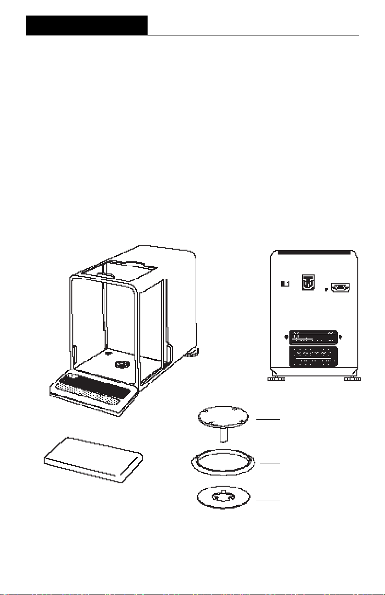
Your ANALYTICAL Plus balance was shipped with the following items:
• Pan assembly (including pan, shield, ring and assembly instructions)
• In-service cover
• AC power cord
• Spare fuse
• Instruction manual
• Warranty card
Remove the contents from the carton and carefully remove all packing material. It is
recommended to save the carton and packing material for storing and/or transporting
the balance. Verify that all of the components have been included and there has been
no damage during shipment.
ANALYTICAL
BALANCE
In-Service Cover
Plus
REAR VIEW
Pan
Ring
Shield
8
INSTALLATION
INSTALLATIONINSTALLATION
INSTALLATION
INSTALLATIONINSTALLATION
EnvironmentEnvironment
Environment
EnvironmentEnvironment
The balance should always be used in an environment which is free from excessive
air currents, corrosives, vibration, and temperature or humidity extremes. These
factors will affect displayed weight readings.
DO NOT install the balance:
• next to open windows or doors causing drafts or rapid temperature changes.
• near air conditioning or heat vents.
• near vibrating, rotating or reciprocating equipment.
• near magnetic fields or devices that
may generate magnetic fields (i.e.
motors, alternators, etc.)
• on an unlevel work surface.
Install the balance in the location where it
will be used before proceeding.
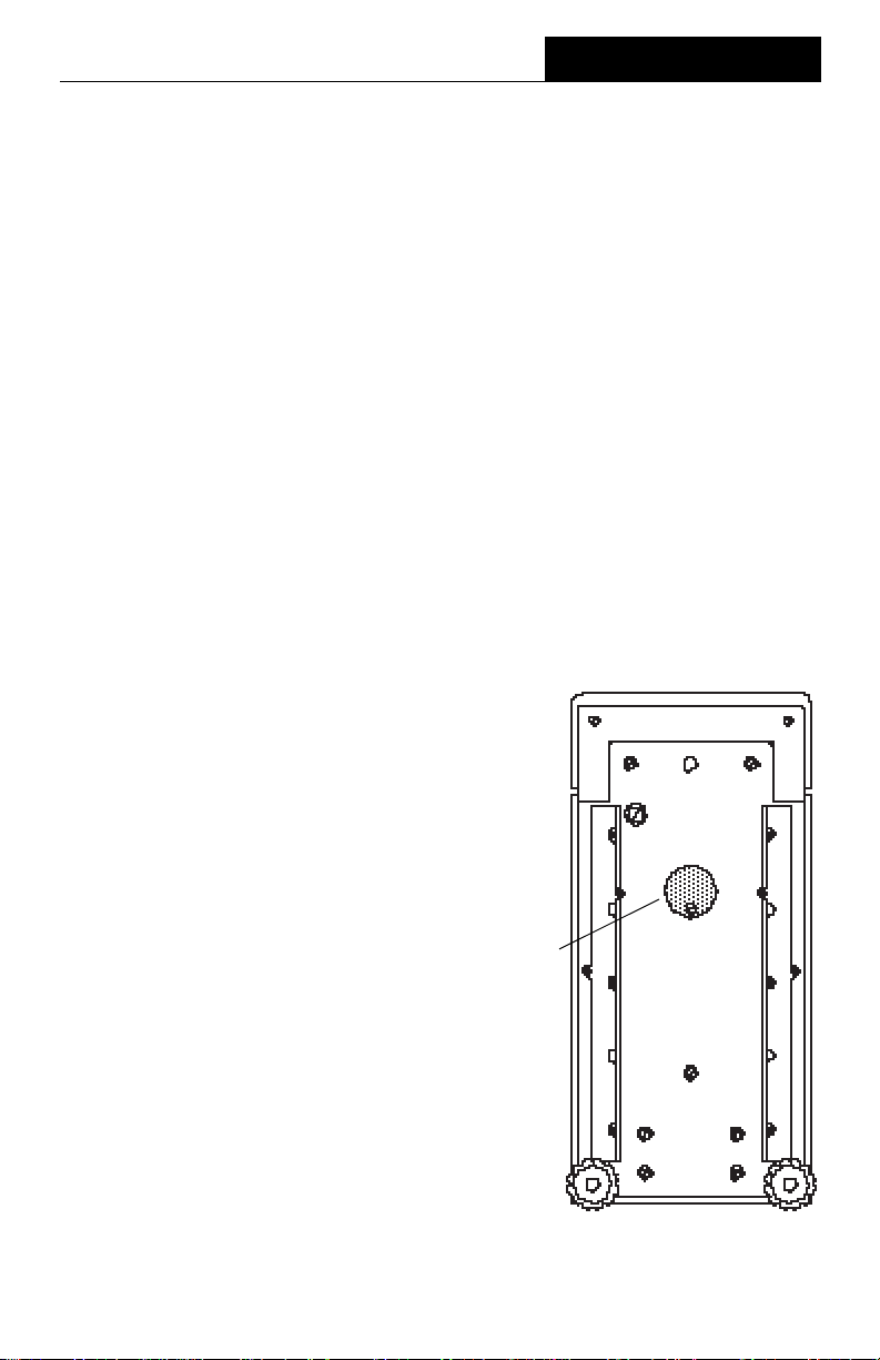
Weigh Below HookWeigh Below Hook
Weigh Below Hook
Weigh Below HookWeigh Below Hook
A weigh below hook is provided inside the
bottom cover under the protective plate
shown in the illustration.
To access the weigh below hook, carefully turn the balance on it's side, loosen
the screw which secures the cover plate,
rotate the plate to clear the hole, then
secure the plate in that position. Return
the balance to an upright position. Mount
the balance on a stable, level elevated
platform and install a hook.
Weigh Below
Hook Cover
Plate
9
INSTALLATION
Leveling the BalanceLeveling the Balance
Leveling the Balance
Leveling the BalanceLeveling the Balance
The balance is equipped with a level indicator on the floor of the weighing chamber
and two adjustable leveling feet at the
rear. Adjust the leveling feet until the
bubble appears in the center circle of the
level indicator.
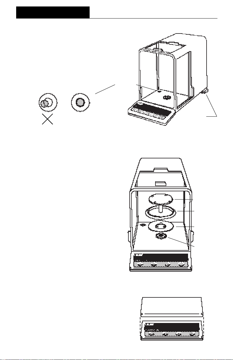
Installing the Pan AssemblyInstalling the Pan Assembly
Installing the Pan Assembly
Installing the Pan AssemblyInstalling the Pan Assembly
1. Place the shield onto the keyed bushing and press it down into place. The
bent tabs must be facing upward and
the shield should be flat against the
chamber floor.
Level
Indicator
Leveling
Feet
Pan
2. Place the ring over the shield. The lip
on the bottom of the ring should fit
against the shield to keep it from
moving.
3. Insert the pan in the load receiver
hole, matching the key on the pan
shaft with the slot in the hole. Gently
press the pan down into place.
In-Service CoverIn-Service Cover
In-Service Cover
In-Service CoverIn-Service Cover
Place the cover snugly over the display
unit.
Ring
Shield
Keyed
Bushing
10
INSTALLATION
RS232 INTERFACERS232 INTERFACE
RS232 INTERFACE
RS232 INTERFACERS232 INTERFACE
ANALYTICAL Plus balances are equipped with a bi-directional RS232 compatible
interface for communication with printers and computers. When the balance is
connected directly to a printer, displayed data can be output at any time by simply
pressing PRINT, or by using the Auto Print feature.
Connecting the balance to a computer enables you to operate the balance from the
computer, as well as receive data such as displayed weight, weighing mode, stability
status, etc.
The following sections describe the hardware and software provided with the balance.
HardwareHardware
Hardware
HardwareHardware
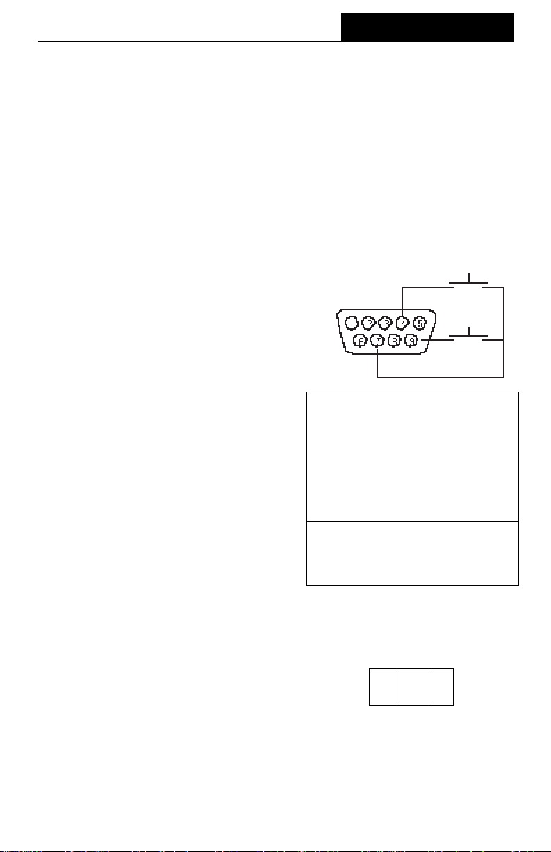
On the rear of the balance, a 9-pin subminiature “D” connector is provided for
interfacing to other devices. The pinout
and pin connections are shown in the
adjacent illustration.
The balance will not output any data unless pin 5 (CTS) is held in an ON state (+3
to +15 V dc). Interfaces not utilizing the
CTS handshake may tie pin 5 to pin 6 to
defeat it.
Output FormatsOutput Formats
Output Formats
Output FormatsOutput Formats
Data output can be initiated in one of three
ways: 1) By pressing PRINT; 2) Using the
Auto Print feature; 3) Sending a print command (“P”) from a computer.
The output format is illustrated in the
RS232 command table which follows.
RS232 CommandsRS232 Commands
RS232 Commands
RS232 CommandsRS232 Commands
1 5 V dc (5 mA max.)
2 Data Out (TXD)
3 Data In (RXD)
4* Tare (External signal)
5 Clear To Send (CTS)
6 Data Terminal Ready (DTR)
7 Ground
8 Request To Send (RTS)
9* Print (External signal)
* External PRINT and/or TARE
switches may be installed as
shown in the diagram. Momentary
contact switches must be used.
TARE *
PRINT *
All communication is accomplished using
standard ASCII format. Only the characters shown in the following table are acknowledged by the balance. Any other
commands, control characters or spaces
are ignored. Commands sent to the balance must be terminated with a carriage
return (CR) or carriage return-line line
feed (CRLF). For example, a tare command should appear as shown in the
adjacent diagram. Data output by the balance is always terminated with a carriage
return - line feed (CRLF).
TARE COMMAND
Field: T CR LF
Length: 1 1 1
11
INSTALLATION
RS232 COMMAND TABLERS232 COMMAND TABLE
RS232 COMMAND TABLE
RS232 COMMAND TABLERS232 COMMAND TABLE
CommandCommand
Command
CommandCommand
CharacterCharacter
Character
CharacterCharacter
? ?
?
Print current unit.
? ?
GRAMS, DWT, CARAT, OZ AV, OZ T, GRAIN,
TAEL 1, TAEL 2, TAEL 3, MOMME,CUSTOM UNIT
DescriptionDescription
Description
DescriptionDescription
Field: Mode Stab CR LF
Length: 5 1 1 1
blank if stable
“ ? ” if unstable
xIxI
xI Set averaging level to "x", where x = 0, 1,
xIxI
xMxM
xM Places balance in mode "x",
xMxM
PP
P Print display data
PP
2
where x = 1 to 11 (see table).
If unit is not already enabled,
command will be ignored.
Length: 10 1 5 1 1 1
Field: Weight Mode Stab CR LF
0 = minimum level
1=
2 = maximum level
1 = grams
2 = pennyweight
3 = carats
4 = avoidupois ounces
5 = troy ounces
6 = grains
7 = taels
8 = mommes
11 = custom unit
When “numeric only” display
data is selected for output in
the RS232 menu, the Mode
field is not output.
hhmmsshhmmss
hhmmss
hhmmsshhmmss
TIMETIME
TIME Print current time.
TIMETIME
mmddyy DATEmmddyy DATE
mmddyy DATE Set current date 'mmddyy'.
mmddyy DATEmmddyy DATE
DATEDATE
DATE Print current date.
DATEDATE
%%
% Print current % ref.
%%
##
# Print current ref., any function.
##
ACAC
AC Abort calibration /Test.
ACAC
CC
C Start an auto calibration.
CC
EE
E Go to initial state of current function.
EE
FF
F Print current function.
FF
MM
M Same as mode button.
MM
xDxD
xD Set 1 second print delay (set x = 0 for OFF, or x = 1 for ON).
xDxD
IDID
ID Print current ID string.
IDID
xxxxIDxxxxID
xxxxID Enter ID string (xxxx limit to 8 characters).
xxxxIDxxxxID
TIME TIME
TIME Set current time to "hh: mm: ss", hh is between 0 - 23.
TIME TIME
Displayed weight sent right justified
w/lead zero blanking.
Nine characters include:
decimal point (1)
weight (7 max))
polarity (1): blank if positive
Same as ?
command
“ - ” if negative
12

INSTALLATION
CommandCommand
Command
CommandCommand
CharacterCharacter
Character
CharacterCharacter
xSxS
xS Set stable data only printing (set x = 0 for OFF, or x = 1 for ON.
xSxS
TT
T Same effect as pressing on tare button.
TT
VV
V Print EPROM version
VV
DescriptionDescription
Description
DescriptionDescription
Field: Model # 1 EPROM # CR LF
Length: 6 16 1 1
Balance Model
x#x#
x# Set current ref., any function, CW takes two reference separated by
x#x#
"98101-xx Sr#x.xx"
a space.
x%x%
x% Doanloads reference weight "x" for percent mode. "x" must be in
x%x%
grams. Command is ignored if percent mode is disabled. If percent
mode is enabled, balance will automatically switch to percent mode
display.
xFxF
xF Set current function to "x". x = 0 to 6. Setup menu must be unlocked.
xFxF
0 = None
1 = Percent
2 = Parts Counting
3 = Check Weighing
4 = Animal Weighing
5 = Fill Guide
6 = High Point
xZxZ
xZ Set Auto Zero to "x". x = 0 for OFF, x = 1 for ON
xZxZ
xSLxSL
xSL Set stability level. User menu must be unlocked. x = 0 to 3
xSLxSL
ZZ
Z Zero request (Gross tare) if Net/Gross enabled.
ZZ
nnnAnnnA
nnnA Set Auto Print feature to "nnn"(see table).
nnnAnnnA
nnn = 0 Turns feature OFF
nnn = S Output on stability
nnn = C Output is continuous
nnn = 1-256 Sets Auto Print interval
Esc LEsc L
Esc L Prints listing of Setup and Print menu settings.
Esc LEsc L
Esc REsc R
Esc R Resets Setup and Print menus to factory defaults.
Esc REsc R
CAUTION: This will reset RS232 configuration.
Esc SEsc S
Esc S Save current settings.
Esc SEsc S
13
INSTALLATION
Connecting PowerConnecting Power
Connecting Power
Connecting PowerConnecting Power
1. Before connecting the power cord,
check that the line voltage switch located at the rear of the balance is set
correctly for your location. If not, use a
small screwdriver to set the switch
correctly.
2. Make sure the doors to the weighing
chamber are closed.
2. Connect the power cord receptacle to
the plug on the rear of the balance.
3. Plug the power cord into a convenient
AC outlet. The balance signals one
long beep to indicate power has been
applied.
Spare FuseSpare Fuse
Spare Fuse
Spare FuseSpare Fuse
A spare fuse is provided in the fuse holder
as shown in the diagram. All models use a
160 mA/250 V fuse.
For 110/120 VAC
For 220/240 VAC
Line
Voltage
Switch
Power
Connection
Active Fuse
Spare Fuse
Fuse Holder
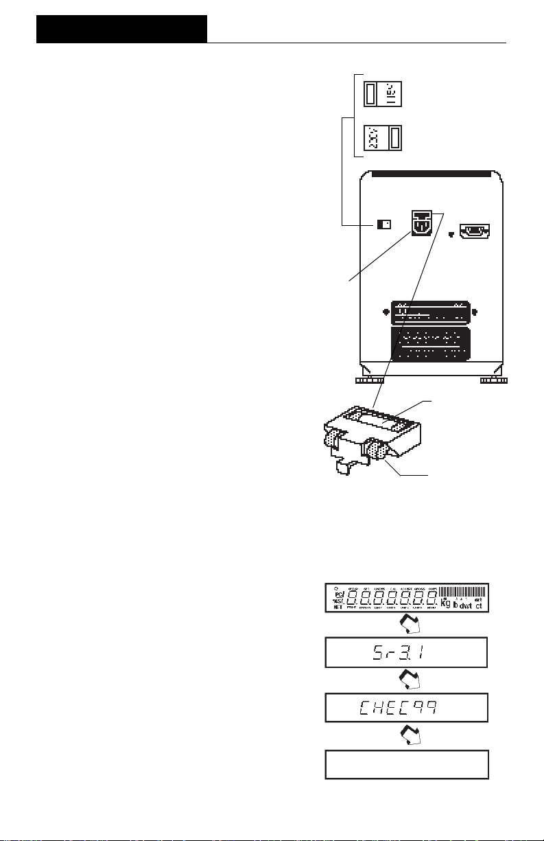
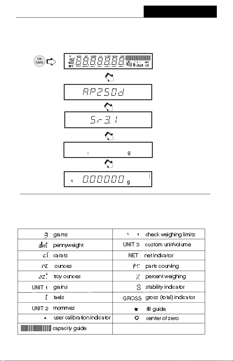
Self TestSelf Test
Self Test
Self TestSelf Test
When power is applied to the balance, it
begins a self test cycle. During this time,
the display cycles as shown.
NOTENOTE
NOTE: Sr shown in the display is the
NOTENOTE
software revision and may be different in
your balance.
After the self test is completed, the display
turns off. Allow the balance to stabilize for
about 2 hours before using it.
14
OPERATIONOPERATION
OPERATION
OPERATIONOPERATION
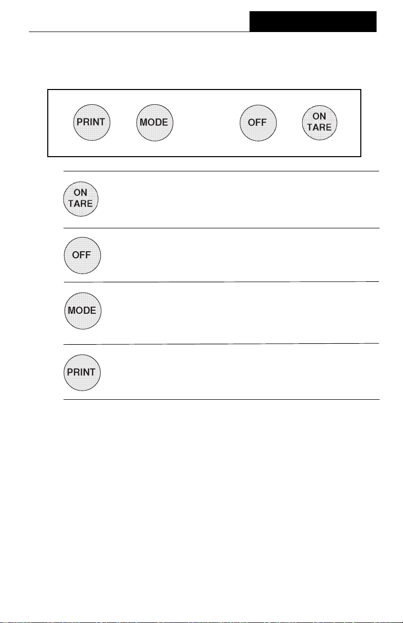
Switch FunctionsSwitch Functions
Switch Functions
Switch FunctionsSwitch Functions
OPERATION
Press and ReleasePress and Release
Press and Release:
Press and ReleasePress and Release
Turns on the balance if it is off, zeros the balance. In the menu
system, this button is used to accept a choice or enter a submenu.
Press and ReleasePress and Release
Press and Release:
Press and ReleasePress and Release
Turns the balance off.
Press and ReleasePress and Release
Press and Release:
Press and ReleasePress and Release
Selects weighing units functions or options. In menus, changes to
next step or value.
Press and ReleasePress and Release
Press and Release:
Press and ReleasePress and Release
Sends weight data, statistical data, GLP data to computer/printer. In
menus, allows returning to a previous menu step.
Before using the balance, carefully review the Symbols Used for Operation of the
Balance shown on page 16, Navigating the Menus on page 71and Operational Guide/
Index on page 18.
Please read the entire manual as there are many features which can be enabled. The
balance is shipped from the factory ready to operate with default settings as shown in
the menus.
The balance is a high precision instrument and will give you years of service if kept
clean and handled carefully. If you have any problems operating the instrument or
require additional information, please feel free to contact our Customer Service
Department at (800) 526-0659.
15
OPERATION
Symbols Used for Operation of the BalanceSymbols Used for Operation of the Balance
Symbols Used for Operation of the Balance
Symbols Used for Operation of the BalanceSymbols Used for Operation of the Balance
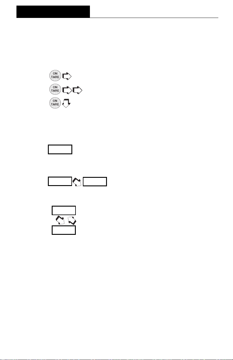
This instruction manual uses certain symbols to explain various operational procedures and actions that occur. Examples of the symbols used are shown as follows:
Pushbutton SwitchesPushbutton Switches
Pushbutton Switches:
Pushbutton SwitchesPushbutton Switches
Display Area Display Area
Display Area:
Display Area Display Area
NORMAL PRESS AND RELEASENORMAL PRESS AND RELEASE
=
NORMAL PRESS AND RELEASE
NORMAL PRESS AND RELEASENORMAL PRESS AND RELEASE
MULTIPLE PRESSMULTIPLE PRESS
=
MULTIPLE PRESS
MULTIPLE PRESSMULTIPLE PRESS
PRESS AND HOLD FOR DESIRED DISPLAYPRESS AND HOLD FOR DESIRED DISPLAY
=
PRESS AND HOLD FOR DESIRED DISPLAY
PRESS AND HOLD FOR DESIRED DISPLAYPRESS AND HOLD FOR DESIRED DISPLAY
DISPLAY AREA - AS A RESULT OF USER ACTIONDISPLAY AREA - AS A RESULT OF USER ACTION
DISPLAY AREA - AS A RESULT OF USER ACTION
DISPLAY AREA - AS A RESULT OF USER ACTIONDISPLAY AREA - AS A RESULT OF USER ACTION
DISPLAY AREA -SWITCHES BACK AND FORTHDISPLAY AREA -SWITCHES BACK AND FORTH
DISPLAY AREA -SWITCHES BACK AND FORTH
DISPLAY AREA -SWITCHES BACK AND FORTHDISPLAY AREA -SWITCHES BACK AND FORTH
DISPLAY AREA - AUTO CHANGE OCCURSDISPLAY AREA - AUTO CHANGE OCCURS
DISPLAY AREA - AUTO CHANGE OCCURS
DISPLAY AREA - AUTO CHANGE OCCURSDISPLAY AREA - AUTO CHANGE OCCURS
16
OPERATION
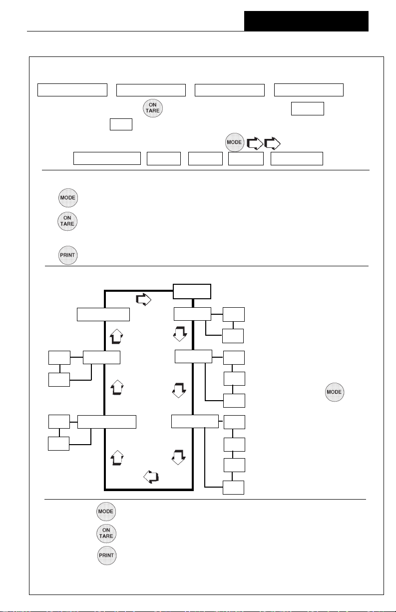
Navigating the MenusNavigating the Menus
Navigating the Menus
Navigating the MenusNavigating the Menus
There are
CALIBRATION USER SETUP PRINT
To enter the menusTo enter the menus
To enter the menus, the
To enter the menusTo enter the menus
When released, CAL is displayed which is the Calibration menu.
four menusfour menus
four menus used in the balance:
four menusfour menus
button is pressed and held until MENU is displayed.
When in the menusWhen in the menus
When in the menus, repeated pressing of
When in the menusWhen in the menus
menus. CALIBRATION USER SETUP PRINT END
advances through the
MENU
Each menu contains selections (submenus) which can be set for specific operations.
The button is used to advance though the submenu selections.
The
button enters or accepts the submenu selection and returns to the beginning
of the submenu selection.
The
The following sample illustrates the
button is used to backup in the submenu if a change is desired.
USER menu USER menu
USER menu and submenu items
USER menu USER menu
USER
NOTE:NOTE:
NOTE:
NOTE:NOTE:
END USER RESET YES
<
ON DUAL * AL 0
<
<
OFF 1
<
<
>
NO
>
<
Each menu is constructed
in the form of a loop. Advancing from one sub-
<
<
menu item to the next by
using the button
2
will eventually return to
<
ON AUTO ZERO STABILITY 0
<
<
OFF 1
>
<
<
the beginning of the menu
.
* Only on AP250D Models.
<
2
<
3
RULES: UseRULES: Use
RULES: Use
RULES: UseRULES: Use
Use Use
Use
Use Use
Use Use
Use
Use Use
After selections are made, always exit menus through END After selections are made, always exit menus through END
After selections are made, always exit menus through END
After selections are made, always exit menus through END After selections are made, always exit menus through END
store settings. store settings.
store settings.
store settings. store settings.
button to advance.button to advance.
button to advance.
button to advance.button to advance.
button to enter or accept submenu.button to enter or accept submenu.
button to enter or accept submenu.
button to enter or accept submenu.button to enter or accept submenu.
button to backup.button to backup.
button to backup.
button to backup.button to backup.
17
MENU MENU
MENU
MENU MENU
to to
to
to to

OPERATION
Operational Guide/IndexOperational Guide/Index
Operational Guide/Index
Operational Guide/IndexOperational Guide/Index
The Operational Guide/Index lists the pages for all balance operations and options.
After settings are made, exit menus to save settings.
FUNCTION FUNCTION
FUNCTION
FUNCTION FUNCTION
1.1.
Turning the Balance ONTurning the Balance ON
1.
Turning the Balance ON
1.1.
Turning the Balance ONTurning the Balance ON
2.2.
Weighing (grams)Weighing (grams)
2.
Weighing (grams)
2.2.
Weighing (grams)Weighing (grams)
3.3.
TaringTaring
3.
Taring
3.3.
TaringTaring
4.4.
Percent WeighingPercent Weighing
4.
Percent Weighing
4.4.
Percent WeighingPercent Weighing
5.5.
Parts CountingParts Counting
5.
Parts Counting
5.5.
Parts CountingParts Counting
6.6.
Check weighingCheck weighing
6.
Check weighing
6.6.
Check weighingCheck weighing
7.7.
Animal WeighingAnimal Weighing
7.
Animal Weighing
7.7.
Animal WeighingAnimal Weighing
8.8.
Fill GuideFill Guide
8.
Fill Guide
8.8.
Fill GuideFill Guide
9.9.
High PointHigh Point
9.
High Point
9.9.
High PointHigh Point
10.10.
Printing DataPrinting Data
10.
Printing Data
10.10.
Printing DataPrinting Data
11.11.
ListList
11.
List
11.11.
ListList
12.12.
Menu LockoutMenu Lockout
12.
Menu Lockout
12.12.
Menu LockoutMenu Lockout
13.13.
CalibrationCalibration
13.
Calibration
13.13.
CalibrationCalibration
14.14.
NetNet
14.
14.14.
15.15.
15.
15.15.
16.16.
16.
16.16.
17.17.
17.
17.17.
18.18.
18.
18.18.
19.19.
19.
19.19.
20.20.
20.
20.20.
21. Changing Units21. Changing Units
21. Changing Units
21. Changing Units21. Changing Units
22.22.
22.
22.22.
23.23.
23.
23.23.
24.24.
24.
24.24.
25.25.
25.
25.25.
26.26.
26.
26.26.
27.27.
27.
27.27.
28.28.
28.
28.28.
29.29.
29.
29.29.
30.30.
30.
30.30.
/Gross Weighing/Gross Weighing
Net
/Gross Weighing
NetNet
/Gross Weighing/Gross Weighing
Custom UnitsCustom Units
Custom Units
Custom UnitsCustom Units
GLPGLP
GLP
GLPGLP
TimeTime
Time
TimeTime
DateDate
Date
DateDate
LockswitchLockswitch
Lockswitch
LockswitchLockswitch
Legal for TradeLegal for Trade
Legal for Trade
Legal for TradeLegal for Trade
StatisticsStatistics
Statistics
StatisticsStatistics
Averaging LevelAveraging Level
Averaging Level
Averaging LevelAveraging Level
StabilityStability
Stability
StabilityStability
Auto ZeroAuto Zero
Auto Zero
Auto ZeroAuto Zero
Dual Range (AP250D)Dual Range (AP250D)
Dual Range (AP250D)
Dual Range (AP250D)Dual Range (AP250D)
Reset UserReset User
Reset User
Reset UserReset User
Reset SetupReset Setup
Reset Setup
Reset SetupReset Setup
Reset PrintReset Print
Reset Print
Reset PrintReset Print
CommunicationsCommunications
Communications
CommunicationsCommunications
TO OPERATETO OPERATE
TO OPERATE
TO OPERATETO OPERATE
( (
(See pages) (See pages)
( (
1919
19
1919
2020
20
2020
2020
20
2020
2121
21
2121
2222
22
2222
2323
23
2323
2424
24
2424
2525
25
2525
2626
26
2626
27 to 3227 to 32
27 to 32
27 to 3227 to 32
2828
28
2828
3434
34
3434
35 to 3735 to 37
35 to 37
35 to 3735 to 37
--------
----
--------
--------
----
--------
--------
----
--------
--------
----
--------
--------
----
--------
--------
----
--------
--------
----
--------
--------
----
--------
--------
----
--------
--------
----
--------
--------
----
--------
--------
----
--------
--------
----
--------
--------
----
--------
--------
----
--------
--------
----
--------
--------
----
--------
SETUPSETUP
SETUP
SETUPSETUP
--------
----
--------
--------
----
--------
--------
----
-------4444
44
4444
44, 4944, 49
44, 49
44, 4944, 49
44, 4944, 49
44, 49
44, 4944, 49
44, 5244, 52
44, 52
44, 5244, 52
44, 5244, 52
44, 52
44, 5244, 52
4444
44
4444
56, 57, 61 to 6556, 57, 61 to 65
56, 57, 61 to 65
56, 57, 61 to 6556, 57, 61 to 65
56, 6556, 65
56, 65
56, 6556, 65
--------
----
--------
--------
----
-------4646
46
4646
4646
46
4646
48, 6048, 60
48, 60
48, 6048, 60
53, 5453, 54
53, 54
53, 5453, 54
5555
55
5555
5656
56
5656
41, 4241, 42
41, 42
41, 4241, 42
4242
42
4242
4545
45
4545
38, 3938, 39
38, 39
38, 3938, 39
38, 3938, 39
38, 39
38, 3938, 39
38, 4038, 40
38, 40
38, 4038, 40
38, 4038, 40
38, 40
38, 4038, 40
3838
38
3838
4242
42
4242
5858
58
5858
58 to 6058 to 60
58 to 60
58 to 6058 to 60
18
OPERATION
Turning the Balance ONTurning the Balance ON
Turning the Balance ON
Turning the Balance ONTurning the Balance ON
1. After the Self Test in the Installation Section is completed (power applied to the
balance), make sure the pan on the balance is clear, then, close the chamber
doors.
2.
Display IndicationsDisplay Indications
Display Indications
Display IndicationsDisplay Indications
The following table describes each of the display indicators.
DISPLAY INDICATORSDISPLAY INDICATORS
DISPLAY INDICATORS
DISPLAY INDICATORSDISPLAY INDICATORS
19
OPERATION
StabilizationStabilization
Stabilization
StabilizationStabilization
Before initally using the balance, allow time for it to adjust to its new environment. The
balance only requires to be plugged in to warm up. Recommended warm up period
is twenty (20) minutes. The balance is powered whenever it is plugged into a power
source.
Auto Range (AP250D and E Only)Auto Range (AP250D and E Only)
Auto Range (AP250D and E Only)
Auto Range (AP250D and E Only)Auto Range (AP250D and E Only)
Modes AP250D and E offer both a fine range (0.01 mg readability from 0 to 52 g) and
a coarse range (0.1 mg over 52 g). When first turned on, the balance is in the fine range.
It remains in this range until the weight on the pan exceeds 52 g. When weight on the
pan is greater than 52 g, the balance switches to the coarse range.
If weight on the pan falls below 52 g, it automatically switches back to the fine range.
WeighingWeighing
Weighing
WeighingWeighing
1. to rezero the display.
2. Place the object(s) or material to be weighed on the pan.
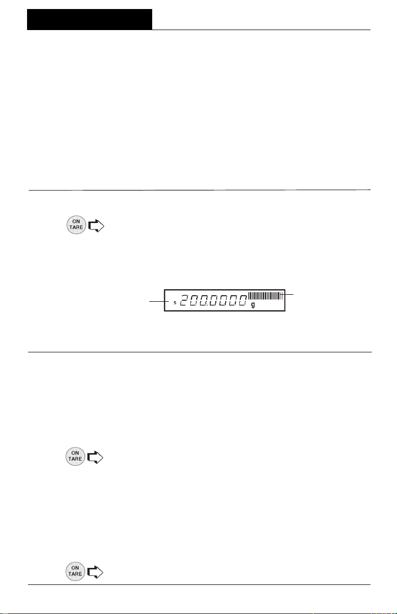
3. Wait for the stability indicator to appear before reading the weight.
STABILITY INDICATOR
CAPACITY GUIDE
NOTENOTE
NOTE: The capacity guide (bars) indicates the percentage of the current weight to
NOTENOTE
the balance capacity. The example above illustrates a 200 gram weight, (balance full
capacity 210 grams).
TaringTaring
Taring
TaringTaring
When weighing material or objects that must be held in a container, taring stores the
container weight in the balance’s memory, separate from the weight of the material in
the container.
1. Place an empty container on the pan. Its weight is displayed.
2. , the display blanks until stable weight readings are received, then
indicates zero. The container’s weight is stored in memory.
3. Add material to the container. As material is added, its net weight is displayed.
4. Removing the container and material from the pan will cause the balance
to display the container’s weight as a negative number.
5. resets the balance to zero.
20
OPERATION
Percent WeighingPercent Weighing
Percent Weighing
Percent WeighingPercent Weighing
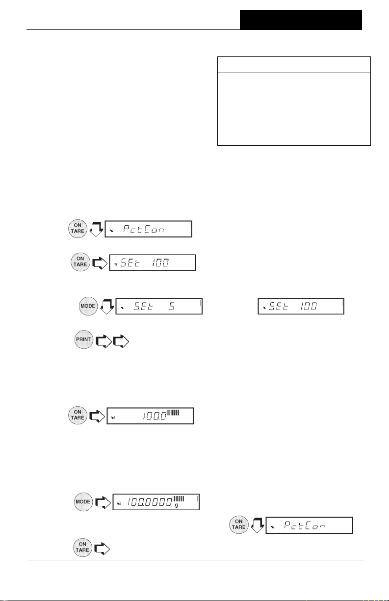
Percent Weighing is
the Percent Function is selected under the
Setup menu. Refer to page 38. Percent
weighing permits you to place a reference
load on the balance, then view other loads
as a percentage of the reference. The load
you place on the platform as a reference
may be displayed as any percentage you
select from 5% to 100% (in 1% increments).
One hundred percent does not necessarily
have to represent the reference load. Subsequent loads, displayed as a percentage
of the reference are limited only by the capacity of the balance. The default setting
is Reference 100%.
To perform percent weighing when in a weighing mode, use the following procedure:
enabled only enabled only
enabled only
enabled only enabled only
when
EXAMPLE EXAMPLE
EXAMPLE
EXAMPLE EXAMPLE
A 10g reference load is set for 20%:
• A subsequent load of 100 g will be
displayed as 200%.
• A subsequent load of 200 g will be
displayed as 400%.
1.
2. Place an empty container on the pan (if one will be used).
3.
NOTENOTE
NOTE: The reference percentage can be changed to any value from 5 to 100.
NOTENOTE
4.
NOTENOTE
NOTE:
NOTENOTE
command through the RS232 Interface, where x = 5 to 100.
5. When the selected reference value appears on the display, place the
reference load in the container (or directly on the pan if no container is used).
8.
the percentage entered. The bar graph indicates the load relative to the
capacity of the balance.
9. Remove the reference load from the balance and replace it with another
load. The second load is displayed as a percentage of the reference.
10.
does not return to a lower number. Instead, it sends Set x%
.
. This is the current reference percentage.
increments to .
, display indicates the reference load as
to view alternate display in units.
11.To restart percent weighing at any time,
12. to exit to a weighing mode.
21
.
OPERATION
Parts CountingParts Counting
Parts Counting
Parts CountingParts Counting
Parts Counting is
Setup menu. Refer to page 38. In the parts counting mode, the balance displays the
quantity of parts you place on the pan. Since the balance determines the quantity
based on the average weight of a single part, all parts must be reasonably uniform in
weight. The accuracy of parts counting results is determined by the error level entered
in PC Err of the Setup Options submenu. Refer to page 43. The default setting for PC
Err is off.
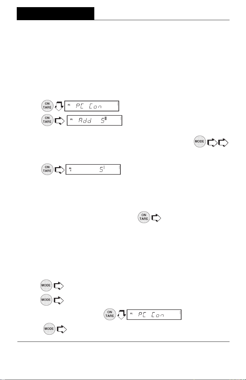
To perform parts counting when in a weighing mode, use the following procedure:
enabled onlyenabled only
enabled only
enabled onlyenabled only
when the Parts Counting Function is selected in the
1.
2.
to use as a reference for counting. The default for the sample size is 5 parts,
but this can be changed to 10, 20, 30, 40, 50, or 100 parts by
(Larger samples yield more accurate results). Add the required number of
sample pieces to the pan.
3. (indicates 5 pieces).
4. If Add X is displayed, the sample is too small to provide results within the
selected error level (PC Error of the Setup Options submenu).
NOTENOTE
NOTE: X represents the number of additional parts needed to provide a sufficient
NOTENOTE
sample.
5. Add the required number of parts, then
6. To count additional pieces, add them to the pan. The display indicates the
actual number of pieces based on their sample size. Tolerance will be within
whatever was selected under the Parts Counting Error Level.
NOTENOTE
NOTE: If the balance controls are not touched, the sample size is stored in memory.
NOTENOTE
You can continue to use the balance to measure quantities as long as the
samples to be measured are of the same weight.
7.
. The balance requires a sample of the parts
to display the weight of the pieces on the pan.
.
again.
8. again to display the number of pieces.
9. To restart parts counting,
10.
, the balance returns to a weighing mode.
22
.
OPERATION
Check WeighingCheck Weighing
Check Weighing
Check WeighingCheck Weighing
Check Weighing is
Setup menu. Refer to page 38. Refer to page 43, Check Weighing Options under the
Setup menu to set the Reference Type and Display Type options. In the check
weighing mode, a reference weight can be set into the balance either as a reference
weight on the pan or as a user entered number. The balance display shows either
under, accept or over as each sample is weighed.
reference weight reference weight
If
reference weight was selected under CW Options submenu:
reference weight reference weight
1. With the balance in the weighing mode, .
enabled only enabled only
enabled only
enabled only enabled only
when the Check Weighing Function is selected in the
NOTENOTE
NOTE: If
NOTENOTE
reference numberreference number
reference number was selected, go to step 7.
reference numberreference number
2. Place a sample weight on the pan which is considered to be the under limit
for check weighing.
3.
4. Place a sample weight on the pan which is considered to be the over weight
limit for check weighing.
5.
to either the (Normal, None or Sign) display type previously selected in CW
Options submenu to indicate under, over or acceptacle limits of the objects
being weighed.
6. Check weighing can now be made by removing a sample and placing a new
sample on the pan.
reference numberreference number
If
reference number was selected under the CW Options submenu:
reference numberreference number
7. With the balance in the weighing mode,
8.
9.
10.
11.
12. Repeat steps 10 and 11and set all digits to the desired value. When the last
digit is entered, display changes to an over value to be entered with the
. The display blanks until a stable reading is achieved, then it goes
to return to weighing .
until the first digit (under weight) is correctly displayed.
to accept the value.
.
indicates under value with first digit flashing.
.
first digit flashing
NOTENOTE
NOTE: allows going back.
NOTENOTE
.
23
OPERATION
Check Weighing (Cont.)Check Weighing (Cont.)
Check Weighing (Cont.)
Check Weighing (Cont.)Check Weighing (Cont.)
13. Repeat steps 10 and 11 to set the over value. When the last digit is entered,
the display indicates one of three display modes for check weighing.
14. Check weighing can now be performed by removing a sample and placing a
new sample on the platform.
15.
selected.
Animal WeighingAnimal Weighing
Animal Weighing
Animal WeighingAnimal Weighing
Animal Weighing is
the Setup menu. Refer to page 38. To set options, refer to page 46, Animal Weighing
Options under the Setup Options submenu. Under normal weighing conditions, the
movement of animal subjects on the balance platform causes unstable fluctuating
display readings and corresponding inaccuracies in the weighing result. The Animal
Weighing mode is a feature designed to minimize these fluctuations through a
combination of several digital signal processing techniques.
When used in this mode, the balance automatically detects the presence of a subject
placed on the platform and starts an animal weighing cycle. The balance samples the
weight data for a variable sampling interval and processes the data to filter out the
instabilities by the live animal.
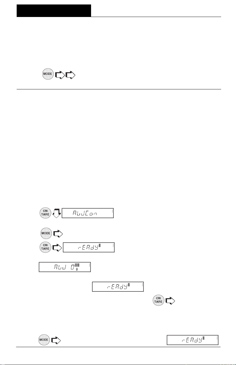
With the balance in a weighing mode, proceed as follows:
1.
2. Place the container on the platform.
NOTENOTE
NOTE:
NOTENOTE
allows other weighing units to be displayed if previously
enabled only enabled only
enabled only
enabled only enabled only
to return to weighing mode.
when Animal Weighing Function is selected under
(Animal Weighing Container).
3.
4. Place the subject in the container. The balance indicates a countdown to
. This cycle accommodates for movement.
The balance then displays the actual weight of the subject with flashing unit
indicator and returns to
Repeat steps 1 through 4 for another subject or to start another
weighing cycle.
NOTENOTE
NOTE: If Auto Print is enabled, the display returns to ready in approximately one
NOTENOTE
second.
5.
to return to weighing mode while display shows .
. The container weight is tared.
after approximately six seconds.
24
Fill GuideFill Guide
Fill Guide
Fill GuideFill Guide
Fill Guide is
enabled onlyenabled only
enabled only
enabled onlyenabled only
when Fill Guide
Function is selected under the Setup menu.
Refer to page 38. To set options, refer to
page 46, Fill Options under the Setup
Options submenu.
OPERATION
FILLGUIDETM BAR GRAPH
The FillGuide
pears in the upper right hand portion of the
TM
is a bar graph which ap-
FILLGUIDE
TM
INDICATOR
display. When the load on the balance is at the balance's capacity, all of the segments
are on. When the load is at half capacity, only the first half of the segments are on.
During normal operation of the balance, the bar graph displays the relationship
between the load on the pan and the capacity of the balance. In the Fill Guide mode,
the bar graph can be set to a desired target value. The FillGuide
TM
feature can be used
in any one of the available weighing units.
The Fill Option under the Setup Options submenu provides two choices for a reference
weight (similar to check weighing). Either a mass can be placed on the pan and used
as a reference weight or a number can be entered to establish the weight value. Both
methods are used to establish a reference for a 100% bar graph reading. Target
parameter provides two choices, one is fill to the reference, the other to zero weight and
Target = to reference..
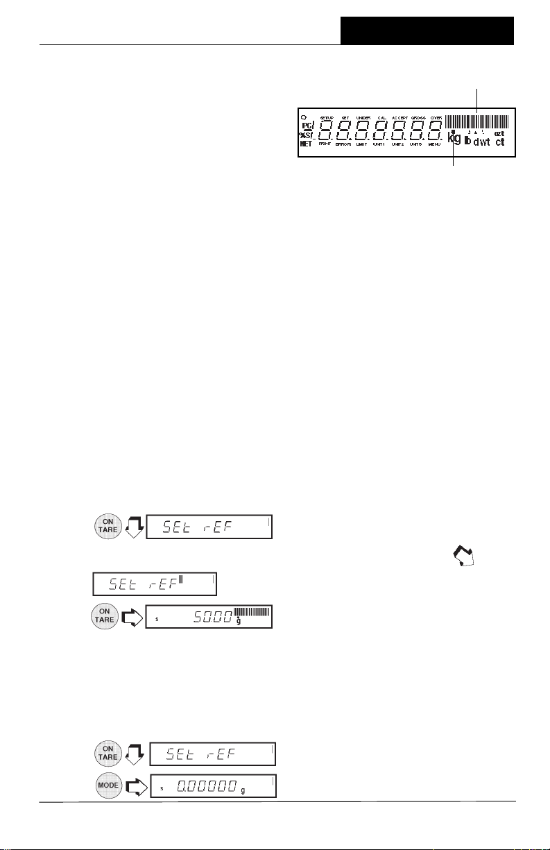
With the balance in a weighing mode, proceed as follows:
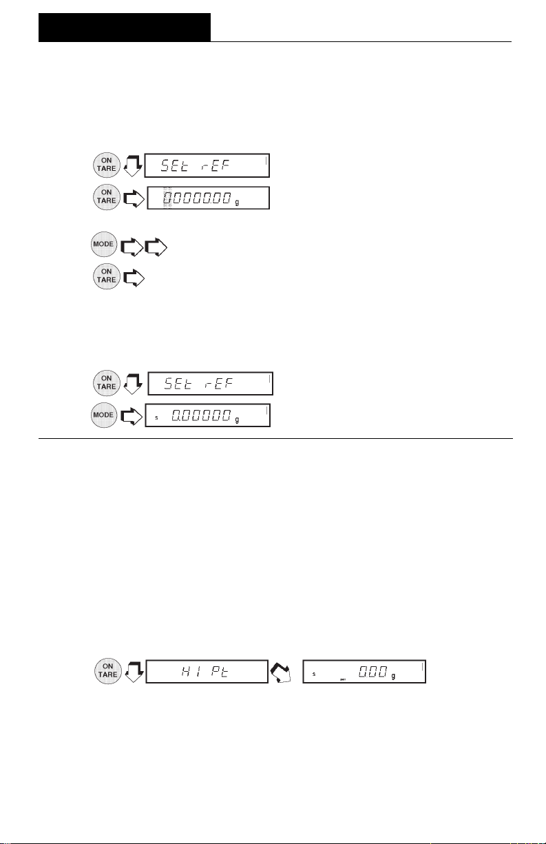
Reference WeightReference Weight
Reference Weight
Reference WeightReference Weight
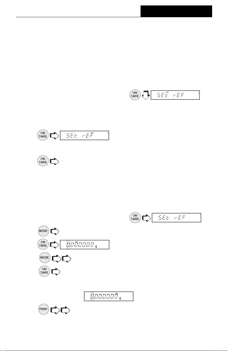
With the balance in a weighing mode, and if reference weight was selected under Fill
Options submenu proceed as follows:
1.
.
2. Place a sample weight on the pan which is the reference weight
. Assumes 50 grams weight reference.
3.
. The display indicates a 50 gram mass
(target = reference. For target = to zero, display shows 0.0000 as the actual
weight of the sample with the bar graph at 100%.
4. The Fill Guide feature can now used by placing samples on the pan. If the
sample is equal to the reference weight used to calibrate the fill mode, the actual
weight is displayed with a full bar graph. When target is selected, the balance
will show the normal weight of the object on the pan.
5.
6.
to exit the fill option mode.
, the balance is now in a weighing mode.
25
OPERATION
Fill Guide (Cont.)Fill Guide (Cont.)
Fill Guide (Cont.)
Fill Guide (Cont.)Fill Guide (Cont.)
Reference NumberReference Number
Reference Number
Reference NumberReference Number
If reference number was selected under the Fill Option submenu with the balance in
a weighing mode, proceed as follows:
1. .
2.
value.
3.
4.
5. Repeat steps 3 and 4 until all digits are set. When the last digit is entered , the
balance is automatically in the fill mode.
6. The fill mode can now be used by placing samples on the pan. If the sample
weight equals the reference weight, the bar graph indicates 100%, the weight
is displayed.
7. to exit the fill option mode.
8.
High PointHigh Point
High Point
High PointHigh Point
High Point is
menu. Refer to page 38. High point is a feature which permits a number of samples
to be weighed with the balance
sample weightsample weight
sample weight
sample weightsample weight
disregarded and not displayed.
NOTENOTE
NOTE: When using this function, the balance does not respond to weights below 100
NOTENOTE
digits.
until the first digit is correctly displayed.
to accept the digit.
enabled onlyenabled only
enabled only
enabled onlyenabled only
. The samples which are in between the low and high points are
when High Point Function is selected under the Setup
storing the loweststoring the lowest
storing the lowest
storing the loweststoring the lowest
. Set the flashing digit to the desired weight
, the balance is now in a weighing mode.
sample weight and the
highest highest
highest
highest highest
With the balance in a weighing mode, proceed as follows:
1.
played, indicating the function is on.
2. Place the first sample on the balance pan. When the balance has stabilized,
the weight is displayed. Remove the weight.
3. Place a second sample on the pan. After the balance stabilizes, the second
sample weight is displayed if it is greater than the first sample. This procedure
can be continued with a number of samples. The highest weight sample is
always displayed.
. , LIMIT is dis-
26
OPERATION
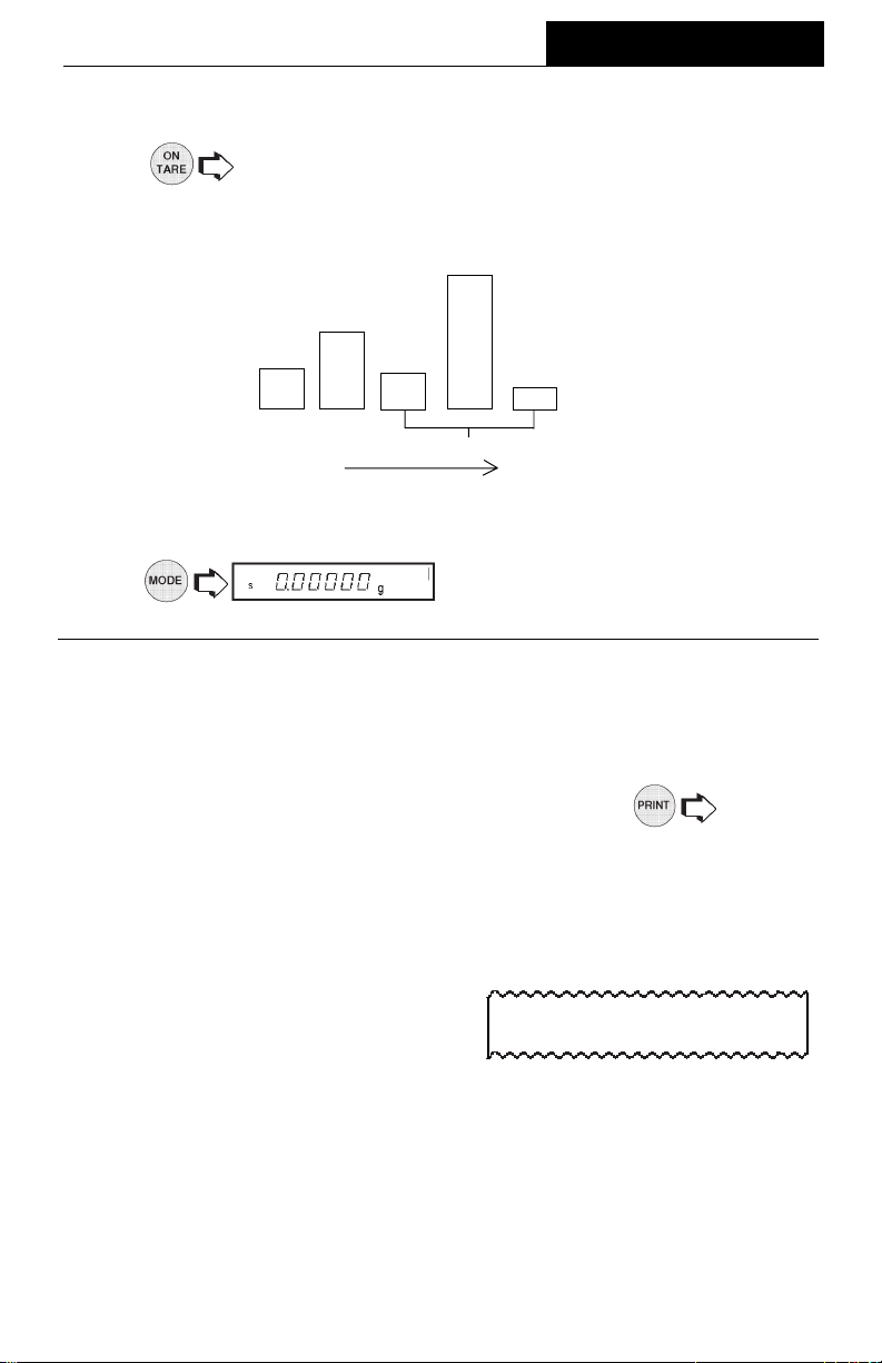
High Point (Cont.)High Point (Cont.)
High Point (Cont.)
High Point (Cont.)High Point (Cont.)
4. To view the lowest and highest sample weight. The display LIMIT
flashes, the lowest sample weight is displayed followed by two short beeps,
the display then indicates the highest sample weight for a few seconds then
automatically changes back to the normal weighing mode.
40g40g
40g
40g40g
20g20g
20g
20g20g
5g5g
5g
5g5g
ORDER SAMPLES TAKEN IN
5. To use the High Point function again, repeat steps 1 through 4.
4g4g
4g
4g4g
NOT DISPLAYED
2g2g
2g
2g2g
6.
mode.
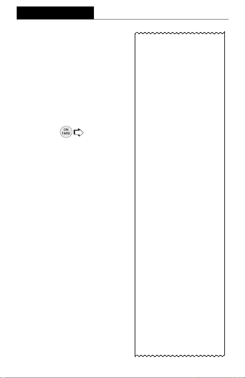
Printing DataPrinting Data
Printing Data
Printing DataPrinting Data
Printing data to an external computer or printer requires that the communications
parameters in the Print menu be set first. Refer to page 51 Print menu. A wide variety
of printing options are available, refer to page 55, Print Options under the Print menu
and set the desired options before proceeding. To print data,
This section defines the various printing setups with printing samples.
Time and DateTime and Date
Time and Date
Time and DateTime and Date
When time and date are entered in the
balance through the Setup menu and with
both Time and Date options set to ON
under the Print Options submenu, each
printout starts with the time and date on the
first line.
to exit High Point and return to a weighing
.
6/22/95 1:00:30 PM
27
OPERATION
Printing Data (Cont.)Printing Data (Cont.)
Printing Data (Cont.)
Printing Data (Cont.)Printing Data (Cont.)
ListList
List
ListList
List is a convienent method of examining
which parameters are set up in the balance. The parameters do not show up on
the display but print out when selected.
Both the Setup and Print menus have a
List function.
When LIST is displayed in either the Setup
or Print Menu,
rameters of the User, Setup and Print
menus to be printed on an external printer
or computer screen.
The sample shown, indicates the status in
three menus.
causes the pa-
AP250D 98101-35 Sr# 3.0
183
User Menu
AL = 1, Stb = 1
AZT = On
Setup Menu
LFT is Off
Enabled Modes:
g, dwt,
ct, oz,
oz t, GN
custom
Tael = Hong Kong
Function = Animal Weighing
AW Lev = 1
Statistics On
Std Dev = Pop
Mean = On
Sum = On
Max = On
Min = On
Diff = On
Net = On
GLP
Time/Date On
Bal Id = On
User Id = On
Project # = On
Cal = On
Name = On
Time = US 8:24:06 AM
Date = US 6/22/95
Lock Switch is Off
28
Print Menu
RS-232 = 2400: N: 7: 2
Print Options
Auto Print = Off
Interval = 6
Non - PL = 100.0000g
Non - PH = 200.0000g
Stable Print = Off
Nu = Off
Time = On
Date = On
Print Ref = On
Print Ref = On
Print Diff = Off

Printing Data (Cont.)Printing Data (Cont.)
Printing Data (Cont.)
Printing Data (Cont.)Printing Data (Cont.)
Automatic Calibration PrintoutAutomatic Calibration Printout
Automatic Calibration Printout
Automatic Calibration PrintoutAutomatic Calibration Printout
When performing an Automatic calibration with CAL option (GLP submenu of the
Setup Options submenu set to ON), a
printout is made after calibration is completed.
User Calibration PrintoutUser Calibration Printout
User Calibration Printout
User Calibration PrintoutUser Calibration Printout
When performing User calibration with
CAL option (GLP submenu of the Setup
Options submenu set to ON), a printout is
made after calibration is completed.
OPERATION
- - - - - AUTO SPAN CAL - - - - - 6/22/95 8:42:24 AM
Bal Id 183
Auto. Cal. completed !
Dif: - 0.00136g
ID 2000000
PR 10000
Name........................................
- - - - - END - - - - -
- - - - - USER SPAN CAL - - - - - 6/22/95 8:52:21 AM
Bal Id 183
Cal: 200.0000g
Old: 200.0398g
Dif: 0.0398g
Wt. Ref......................................
ID 2000000
PR 10000
Name........................................
Calibration Test PrintoutCalibration Test Printout
Calibration Test Printout
Calibration Test PrintoutCalibration Test Printout
When performing a Calibration Test with
with CAL option (GLP submenu of the
Setup Options submenu set to ON), a
printout is available.
- - - - - END - - - - -
- - - - - CAL TEST - - - - - 6/22/95 8:47:02 AM
Bal Id 183
Cal. test completed !
Dif: -0.00045g
ID 2000000
PR 10000
Name........................................
- - - - - END - - - - -
29
OPERATION
Printing Data (Cont.)Printing Data (Cont.)
Printing Data (Cont.)
Printing Data (Cont.)Printing Data (Cont.)
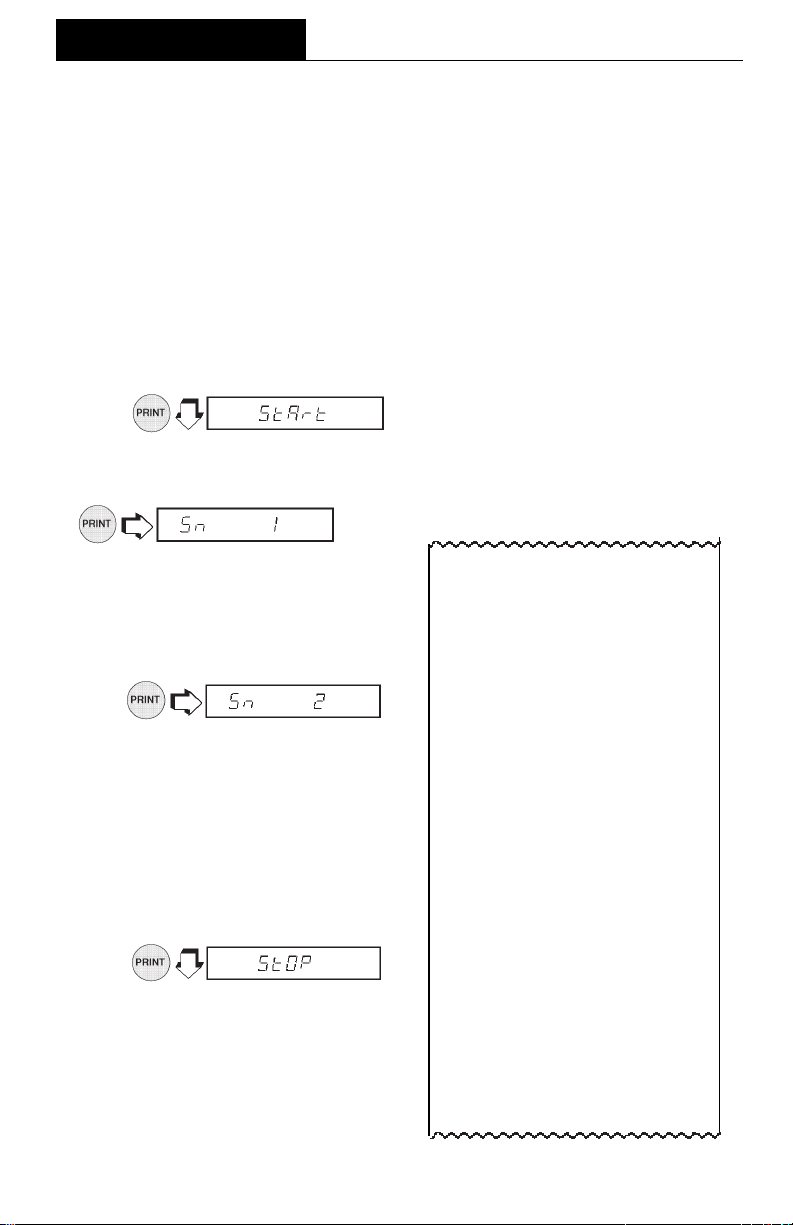
Statistics PrintoutStatistics Printout
Statistics Printout
Statistics PrintoutStatistics Printout
When statistics is enabled, a printout can be made with any of the major balance
functions such as; Percent, Parts Counting, Check Weighing, Animal Weighing and
FillGuide
Enable, Standard Deviation, Mean, Sum, High, Low and Difference which can be
turned on or off. Statistics can be printed any time the balance is operational and
statistics is enabled (turned on).
For example, to weigh ten samples and obtain a printout, proceed as follows:
SamplingSampling
Sampling
SamplingSampling
TM
. Under the Setup Options menu, Statistics has parameters such as
1.
2. Place the
display to show.
appears and the printer outputs the
first sample weight.
4. Remove the first sample.
5. Place the
platform, wait for the stability indi-
cator
6.
appears and the printer outputs
the second sample weight.
7. Remove the second sample.
NOTENOTE
NOTE: The weight of each sample is
NOTENOTE
shown on the display and printed.
Maximum sample size = 256.
8. Repeat procedure for as many
samples as required.
9.
to end the sampling procedure.
Printout completes the data. See
sample at right.
firs
t sample on the platform, wait for the stability indicator
3.
second
S S
S on the display to show.
S S
sample on the
.
S S
S on the
S S
- - - - - START - - - - -
6/22/95 1:40:00 PM
1 200.0369 g
2 200.0372 g
3 200.0370 g
4 200.0369 g
5 200.0371 g
6 200.0372 g
7 200.0372 g
8 200.0369 g
9 200.0369 g
10 200.0371 g
- - - - - - - - - - - - - - - - - - - - -- SD Pop. 0.000119
Mean 200.037030
Sum 2000.03720
Max. 200.03720
Min. 200.03690
Diff 0.00030
Finish 1:43:17 PM
Bal Id 183
ID 2000000
PR 10000
Name......................................
- - - - - - END - - - - - -
30

Printing Data (Cont.)Printing Data (Cont.)
Printing Data (Cont.)
Printing Data (Cont.)Printing Data (Cont.)
Percent WeighingPercent Weighing
Percent Weighing
Percent WeighingPercent Weighing
Statistical printouts of Percent Weighing
are similar to sampling statistics. Loads
on the balance platform may be displayed
as a percentage of a defined sample. To
obtain a printout in this mode, the balance
must be set up in Percent Weighing.
Refer to basic Sampling procedure for
operation. The sample illustration shown
at the right had the balance reference set
to 100% using a weight of 25.22573 grams.
- - - - - START - - - - 6/22/95 9:58:00 AM
1 20 Pcs
2 14 Pcs
3 11 Pcs
4 25 Pcs
5 23 Pcs
- - - - - - - - - - - - - - - - - - - - -- SD Pop. 5.31
Mean 18.60
Sum 93.0
Max. 25.0
Min. 11.0
Diff. 14.0
Finish 10:01:00 AM
PC Ref 0.888604 g
Bal Id 183
ID 2000000
PR 10000
Name....................................
- - - - - - - - END - - - - - -
OPERATION
- - - - - START - - - - -
6/22/95 10:53:24 AM
1 100.0%
2 148.9%
3 46.9%
4 70.4%
5 94.0%
- - - - - - - - - - - - - - - - - - - - -- SD Pop. 34.077
Mean 92.040
Sum 460.20
Max. 148.90
Min. 46.90
Diff 102.00
Finish 10:53:39 AM
Bal Id 183
ID 2000000
PR 10000
Name......................................
- - - - - - END - - - - - -
Parts CountingParts Counting
Parts Counting
Parts CountingParts Counting
When the balance is in a Parts Counting mode, each time a batch of items
are counted, they can be recorded
statistically by pressing
scribed in the Sampling procedure.
The example shown on the left used
a five piece sample weight of 80.2273
grams.
as de-
31

OPERATION
Printing Data (Cont.)Printing Data (Cont.)
Printing Data (Cont.)
Printing Data (Cont.)Printing Data (Cont.)
Check Weighing
When the balance is in a Check Weighing
mode, each sample can be checked to
print an under, accept or over weight on
the printout by setting the Print Options
parameter Difference to ON. Use the
procedure described in Sampling to ob-
tain data by pressing
each time a
sample is weighed.
- - - - - START - - - - 6/22/95 12:09:29 PM
1 17.28667 g
Fill Dif 7.95202 g
2 31.75109 g
Fill Dif 6.51240 g
3 13.85533 g
Fill Dif 11.38335 g
4 200.0372 g
Fill Dif 174.7985 g
5 28.18002 g
Fill Dif 2.94133 g
- - - - - - - - - - - - - - - - - - - - - - - SD Pop. 71.216407
Mean 58.222062
Sum 291.11031
Max. 200.03720
Min. 13.85533
Diff 186.18187
Finish 1:30:25 PM
Fil Ref 25.23869 g
Bal Id 183
ID 2000000
PR 10000
Name.....................................
- - - - - START - - - - 6/22/95 12:09:29 PM
1 5.96781 g
CW UNDER 0.00397 g
2 14.84395 g
CW OVER 2.98037 g
3 20.50947 g
CW OVER 8.64589 g
4 5.96424 g
CW UNDER 0.00753 g
5 8.93100 g
CW ACCEPT 8.93100 g
- - - - - - - - - - - - - - - - - - - - - - - SD Pop. 5.654601
Mean 11.243294
Sum 56.21647
Max. 20.50947
Min. 5.96424
Diff 14.54523
Finish 12:12:57 PM
Min Ref 5.97177 g
Max Ref 11.86358 g
Bal Id 183
ID 2000000
PR 10000
Name.....................................
- - END - - - - - -- - END - - - - - -
- - END - - - - - -
- - END - - - - - -- - END - - - - - -
FillGuideFillGuide
FillGuide
FillGuideFillGuide
- - - -
TMTM
TM
TMTM
When the balance is in the FillGuide
mode, each sample can be checked
against the defined FillGuideTM full capacity and to print the difference on the
printout by setting the Print Options parameter Difference to ON. Use the procedure described in Sampling to obtain data
by pressing
each time a sample is
weighed.
TM
- - - -
- - END - - - - - -- - END - - - - - -
- - END - - - - - -
- - END - - - - - -- - END - - - - - -
32

MENUS
MENUSMENUS
MENUS
MENUSMENUS
Each submenu of the AP Balance contains numerous selections which can be set for
specific operations. To customize the operation of the balance for specific measurements, functions and printing, it is necessary to make selections in each menu. The
following illustration identifies the major items in each menu. The factory default
settings are shown in bold type.
CAL
AUTO
USR
TEST
END
USER
RESET
AL
STABILITY
AUTO ZERO
-dUAL-*
END, USER
YES/NO
11
0,
1, 2
11
11
0,
1, 2, 3
11
ONON
ON/OFF
ONON
ONON
ON/OFF
ONON
SETUP
RESET
YES/NO
LFT
ON/
SEL
gg
g, dwt, ct, oz, oz t,
gg
UNIT 1 (grain), t
UNIT 2 (mommes),
UNIT 3 (custom)
FUNCTIONS
NoneNone
None
NoneNone
Percent
Parts Counting
Check Weighing
Animal Weighing
FillGuide
High Point
SETUP OPTIONS
Statistics
Enable
Standard Dev.
Mean
Sum
High
Low
Difference
End, Statistics
Net
Custom Units
Factor
Density
End
GLP
Time
BAL ID #
ID #
Project #
Cal
Name
End, GLP
OFFOFF
OFF
OFFOFF
PRINT
RESET
YES/NO
SETUP OPTIONS
(Cont.)
PC Error
CW Option
Reference Type
Displays Type
End, CW Opts.
AW Option
AW0, AW1, AW2,
AW3
TM
Fill Option
Reference Type
Target Direction
End, Fill Opts.
End
TIME
Type
Set
Adjust
End, Time
DATE
Type
Set
End, Date
LOCKSWITCH
LIST
END, SETUP
COMMUNICATION
Baud
300, 1200,
24002400
2400, 4800,
24002400
9600
Data Bits
7 7
7 or 8
7 7
Parity Bit
Odd, Even,
NoneNone
None
NoneNone
Stop Bits
22
1 or
2
22
End, Comm.
GLP
ID #
Project #
End
PRINT OPTIONS
Auto Print
Initialize Auto Pt.
Stable Data
Numeric Data
Time
Date
Reference
Difference
End, Print Opts.
LIST
END, PRINT
* For AP250D only.
33
MENUS
MENU LOCK-OUT PROTECTIONMENU LOCK-OUT PROTECTION
MENU LOCK-OUT PROTECTION
MENU LOCK-OUT PROTECTIONMENU LOCK-OUT PROTECTION
The menus can be locked out to prevent
settings from being changed. When locked
out, Setup and Print menus may still be
accessed for viewing but settings may not
be changed. The word SAFE will be displayed before the menus indicating they
have been locked out.
Before setting menus for Lock or Unlock
in the Loc SW section , this lock-out switch
must be set to Unlock. After selections are
made, set this switch to Lock.
1. Turn the balance OFF.
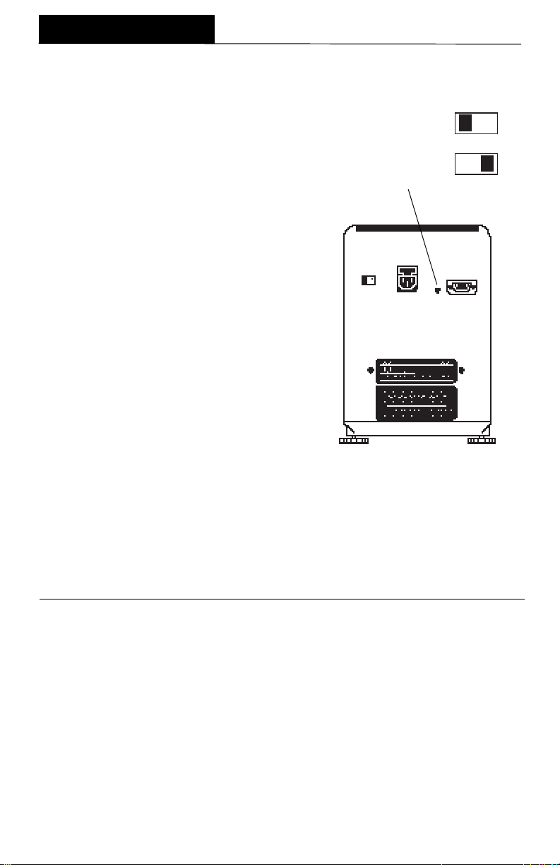
2. Locate the hole plug next to the RS232 Interface connector at the rear of
the balance.
3. Remove the hole plug to access the
switch.
Remove plug to
access switch.
Unlocked
Locked
4. Using a small screwdriver, slide the
switch to the right to lock out, or to the
left to unlock menus.
5. Replace the hole plug.
6. Turn the balance ON again.
34
For verified balances:For verified balances:
For verified balances:
For verified balances:For verified balances:
Place verification label over hole
with switch in locked position.
Fully verified balances are sealed
with the Setup menu locked out.
MENUS
CALIBRATION MENUCALIBRATION MENU
CALIBRATION MENU
CALIBRATION MENUCALIBRATION MENU
Auto Auto
Analytical Plus balances features
is a method where the balance calibrates itself using internal calibrated masses.
USER USER
USER
is a method where the balance
USER USER
known value by entering that value into the balance.
calibration data to be tested against the internal mass being used for the test. The
following figure illustrates the sequence in which submenus appear on the Calibration
menu. Item shown bolded is a default setting.
CALIBRATION MENUCALIBRATION MENU
CALIBRATION MENU
CALIBRATION MENUCALIBRATION MENU
Calibration Menu ProtectionCalibration Menu Protection
Calibration Menu Protection
Calibration Menu ProtectionCalibration Menu Protection
NOTESNOTES
NOTES: 1. Calibration may be locked out to prevent unauthorized personnel
NOTESNOTES
from changing calibration. If calibration has been locked out, you
can only access Test.
USERUSER
Auto
,
USER
Auto Auto
USERUSER
can be calibrated using an external mass of
AUTO
USR
Enter #
TEST
END, Calibration
and
TEST TEST
TEST
calibration methods.
TEST TEST
Test Test
Test
Test Test
allows the stored
AutoAuto
Auto
AutoAuto
2. To lock out calibration menu, after calibration, refer to the section
titled Menu Lock-Out Protection.
Auto CalibrationAuto Calibration
Auto Calibration
Auto CalibrationAuto Calibration
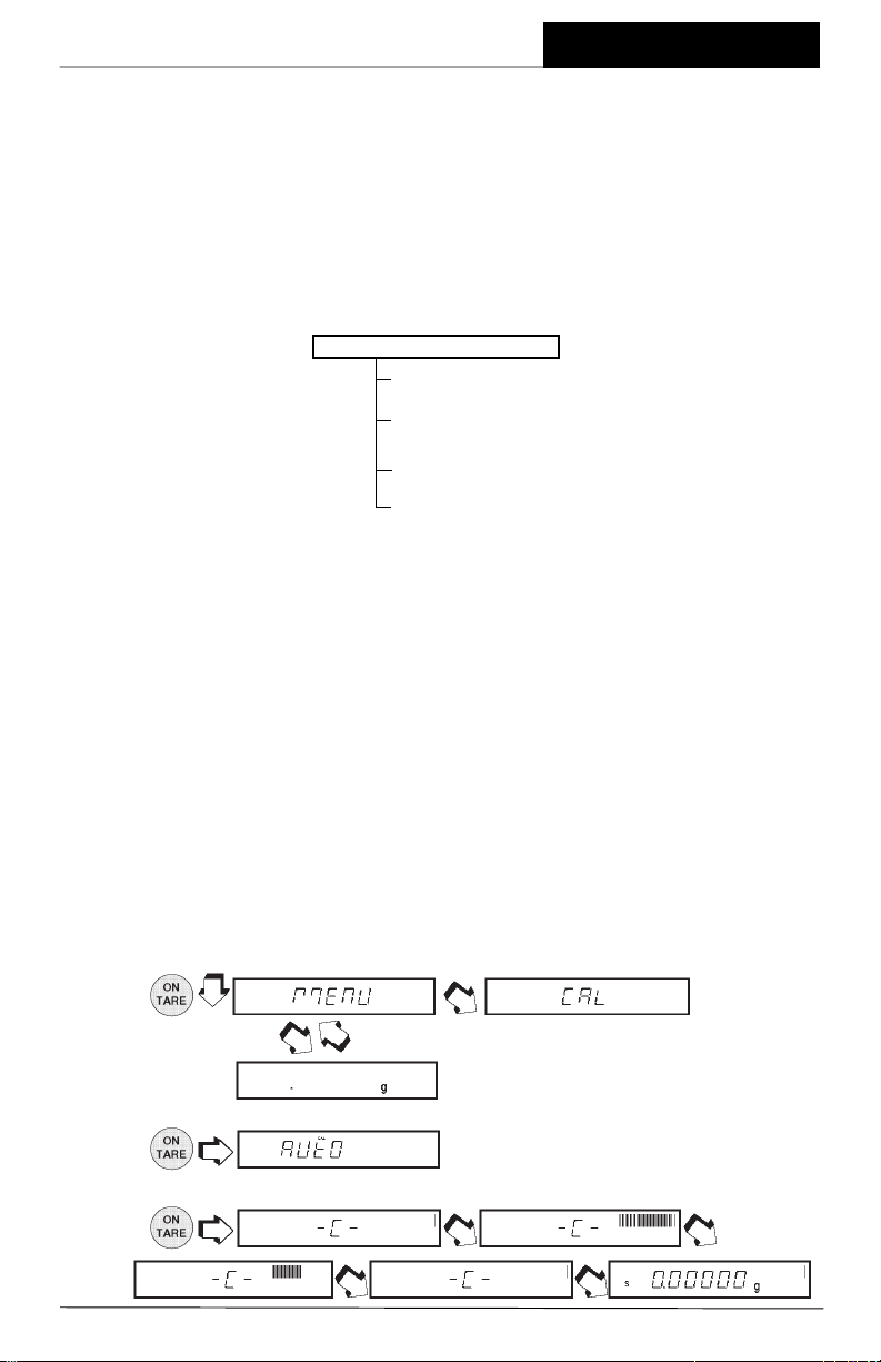
Auto calibration is used when it is desired to calibrate the balance automatically.
Proceed as follows:
1. Make sure there is no load on the pan and close the chamber doors.
2.
3. .
4.
.
.
NOTE: DO NOT DISTURB THENOTE: DO NOT DISTURB THE
NOTE: DO NOT DISTURB THE
NOTE: DO NOT DISTURB THENOTE: DO NOT DISTURB THE
BALANCE WHEN -C- BALANCE WHEN -C-
BALANCE WHEN -C-
BALANCE WHEN -C- BALANCE WHEN -C IS DISPLAYED. IS DISPLAYED.
IS DISPLAYED.
IS DISPLAYED. IS DISPLAYED.
35

MENUS
User CalibrationUser Calibration
User Calibration
User CalibrationUser Calibration
User calibration is used when it is desired to calibrate the balance using a mass of
known value.
NOTENOTE
NOTE: Before beginning user calibration, make sure masses are on hand.
NOTENOTE
If you are in the calibration menu and
realize masses are not available or you do
not want to calibrate, exit the menus and
return to normal weighing.
Refer to the adjacent table for correct mass
values to use with the balance. For optimum calibration, the exact value of masses
should be known. The value will be entered
to four decimal places during the procedure.
Proceed as follows:
1. Make sure there is no load on the pan and close the chamber doors.
USER CALIBRATION MASSESUSER CALIBRATION MASSES
USER CALIBRATION MASSES
USER CALIBRATION MASSESUSER CALIBRATION MASSES
MODELMODEL
MODEL
MODELMODEL
MASS VALUEMASS VALUE
MASS VALUE
MASS VALUEMASS VALUE
AP110S 100 g
AP210S 200 g
AP310S 300 g
AP250D 200 g
Calibration weights must meet or exceed ASTM Class 1 Tolerance. In Europe, use OIML Class E2 weights.
2.
.
3.
4. .
5.
the value of last calibration mass is dis-
played.
6.
7.
to accept value.
to change value of flashing digit.
8. Repeat steps 6 and 7 and set the numbers to match the value of the selected
calibration mass.
9.
10.
11.
+ .
.
= required mass.
12. .
= User Calibration Indicator
36
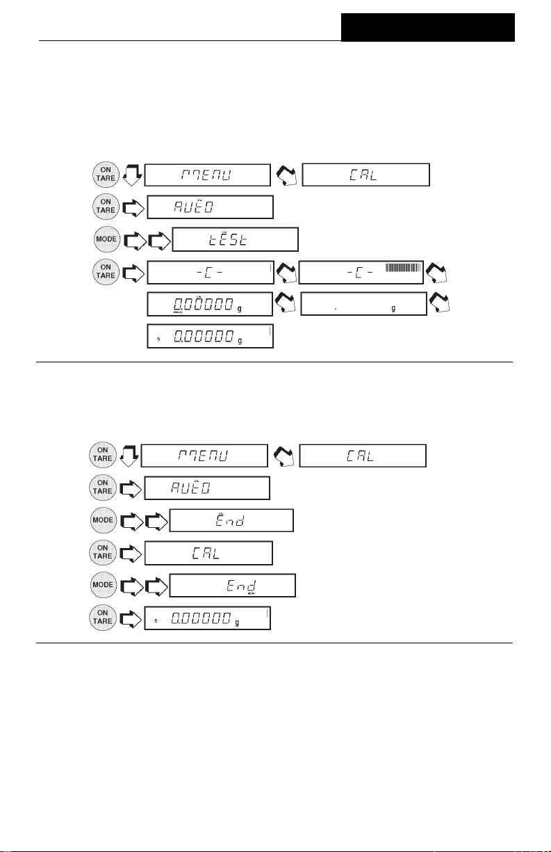
MENUS
Cal TestCal Test
Cal Test
Cal TestCal Test
This feature checks the calibration against last stored calibration information. The Cal
Error display indicates the difference since the last automatic calibration.
1. Make sure there is no load on the pan and close the chamber doors.
2.
3.
4. .
5.
Cal EndCal End
Cal End
Cal EndCal End
To exit the calibration menus, proceed as follows:
1.
2. .
3. .
4.
.
.
.
5.
6.
.
.
37
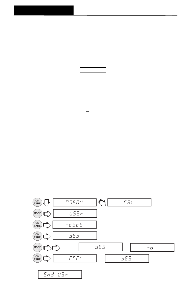
MENUS
USER MENUUSER MENU
USER MENU
USER MENUUSER MENU
The User menu is used to adapt the balance to environmental conditions. It contains
submenus which enable you to turn features on or off, and program balance param-
Reset
eters.
appear if menu has been locked out. AL specifies the averaging level.
the desired stability range.
set on, enables dual range function on model AP250D.
User menu and store the selections. The following figure illustrates the sequence in
which submenus appear on the User menu. Items shown in bold type are the default
settings.
User Menu ProtectionUser Menu Protection
User Menu Protection
User Menu ProtectionUser Menu Protection
The User menu may be locked out to prevent unauthorized personnel from changing
the settings. If -SAFE- is displayed, the User menu has been locked out. Settings
may be viewed but not changed. To lock out the User menu, refer to the section titled
Menu Lock-Out Protection.
ResetReset
Reset
ResetReset
changes all submenus to original factory default settings.
Auto Zero
sets the automatic zero threshold.
End User
USER MENUUSER MENU
USER MENU
USER MENUUSER MENU
RESET
YES/NO
AL
11
0,
1, 2
11
STABILITY
11
0,
1, 2, 3
11
AUTO ZERO
ONON
ON/OFF
ONON
-dUAL-
ONON
ON/OFF
ONON
END, User
is used to exit the
Reset
STB
Dual,
does not
specifies
when
This submenu enables you to reset all User menu selections to the
settings:
Range
Averaging Level
ON. ON.
ON. Reset does not appear if the menu has been locked out.
ON. ON.
1.
2.
3.
4.
5.
6.
balance signals a
.
.
.
.
. If is selected, the
.
11
1, Stability Range
11
to select or .
long beep
. Reset values are stored only if exited through
1, 1,
1, Auto-Zero Tracking
1, 1,
38
factory default
ONON
ON and Dual
ONON

MENUS
Averaging LevelAveraging Level
Averaging Level
Averaging LevelAveraging Level
Averaging level compensates for vibration or excessive air currents. Factory default
setting is shown in bold type.
AL 0 reduced stability, fastest stabilization time
AL 1 normal stability, normal stabilization timeAL 1 normal stability, normal stabilization time
AL 1 normal stability, normal stabilization time
AL 1 normal stability, normal stabilization timeAL 1 normal stability, normal stabilization time
AL 2 more stability, slow stabilization time
NOTENOTE
NOTE: Averaging level does not affect balance accuracy, but it does affect stabiliza-
NOTENOTE
tion time.
To view or change the averaging level:
1. Access the Averaging Level submenu.
2.
3.
4.
Stability RangeStability Range
Stability Range
Stability RangeStability Range
The stability range specifies the weighing results must be within a preset tolerance limit
for a certain time to turn the stability indicator ON. When a displayed weight changes
beyond the allowable range, the stability indicator turns OFF, indicating an unstable
condition. Factory default setting is shown in bold type.
weight is within a preset tolerance limit for several seconds.
When the RS232 interface is configured to print stable data only, the stability range also
governs data output. Displayed data will only be output if it is within the selected stability
range.
To view or change the stability range:
1. Access the Stability Range
to select through .
Stb 0 Smallest range: stability indicator is ON only when displayed
Stb 1Stb 1
Stb 1
Stb 1Stb 1
Stb 2 Larger range.
Stb 3 Largest range: stability indicator is ON when displayed
weight is within a preset tolerance limit for one second.
Normal range.Normal range.
Normal range.
Normal range.Normal range.
.
.
submenu.
2.
3.
4.
to select through .
.
.
39
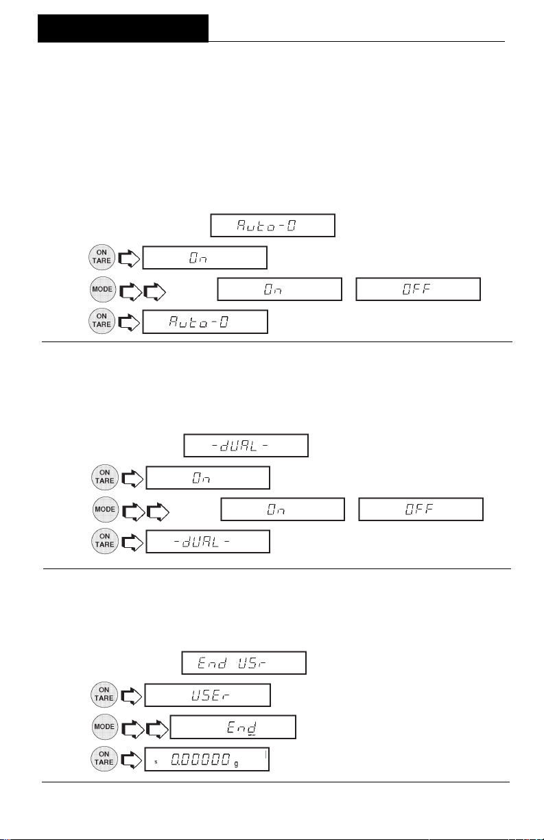
MENUS
Auto-ZeroAuto-Zero
Auto-Zero
Auto-ZeroAuto-Zero
Auto-Zero minimizes the effects of temperature changes and shift on the zero reading.
The balance maintains the zero display until the threshold is exceeded. Factory default
setting is shown in bold type.
OFF Turns Auto-Zero OFF.
OnOn
On
OnOn
To view or change the auto-zero setting:
1. Access the Auto-Zero submenu.
Turns Auto-Zero ON.Turns Auto-Zero ON.
Turns Auto-Zero ON.
Turns Auto-Zero ON.Turns Auto-Zero ON.
2.
3.
4.
Dual Range FunctionDual Range Function
Dual Range Function
Dual Range FunctionDual Range Function
Enables dual range operation on model AP250D only. To turn the feature ON,
proceed as follows:
1. Access the Dual
2. .
3.
4.
Exiting User MenuExiting User Menu
Exiting User Menu
Exiting User MenuExiting User Menu
To exit the User menu and store settings, proceed as follows:
to select or .
to select or .
.
.
submenu.
.
1. Access End Usr
2. .
3.
4.
submenu.
.
.
40

MENUS
SETUP MENUSETUP MENU
SETUP MENU
SETUP MENUSETUP MENU
The Setup menu is used to customize the operation of the balance for your specific
requirements. It contains submenus which enable you to turn features on or off, and
program balance parameters.
Reset
settings.
does not appear if menu has been locked out.
for type approved operation.
a custom unit for specialized applications.
items, only one at a time can be selected for operation. The functions are: Percent,
Parts Counting, Check Weighing, Animal Weighing, FillGuideTM or High Point. Several
of these functions have submenus under the Setup Options Menu which permit
various options to be selected and printed.
follows: Statistics, Net, Custom Units, Good Laboratory Practices, Parts Counting
Error, Check Weighing Options, Animal Weighing Options, Fill Options, Time, Date,
Lock Switch, List and End. The following figure illustrates the sequence in which
submenus appear on the Setup menu. Areas shaded only appear in the menu if the
appropriate function or weighing unit is selected. Items shown in bold type are the
default settings.
SETUP MENU SETUP MENU
SETUP MENU
SETUP MENU SETUP MENU
RESET
YES/NO
LFT
OFFOFF
ON/
OFF
OFFOFF
SELECTION, UNITS
gg
g, dwt, ct, oz, oz t,
gg
UNIT 1 (grain), t,
UNIT 2 (mommes),
UNIT 3 (custom)
FUNCTIONS
NoneNone
None
NoneNone
Percent
Parts Counting
Check Weighing
Animal Weighing
TM
FillGuide
High Point
SETUP OPTIONS
Statistics
Enable
OFFOFF
ON/
OFF
OFFOFF
Standard Dev.
pop, sample,
Mean
OFFOFF
ON/
OFF
OFFOFF
Sum
OFFOFF
ON/
OFF
OFFOFF
High
OFFOFF
ON/
OFF
OFFOFF
Low
OFFOFF
ON/
OFF
OFFOFF
Difference
OFFOFF
ON/
OFF
OFFOFF
End, Statistics
Net
OFFOFF
ON/
OFF
OFFOFF
Reset
changes all submenus to original factory default
LFT
SEL
(selection) specifies one of nine weighing units with
OFF OFF
OFF
OFF OFF
Functions
Setup Options
SETUP OPTIONS (Cont.)
Custom Units, Unit 3
Factor
Mantissa
Enter #
Exponent
-3, -2, -1,
LSD
.5,
Density
nonenone
none, l, ml, fl oz, qt
nonenone
End
GLP
Time /Date
ON/
Bal ID
ON/
ID #
ON/
Proj. #
ON/
Cal
ON/
Name
ON/
End, GLP1
Parts Counting Error %
.1,. 25, .5, 1, 2.5, 5,
Check Weighing Opts.
Reference.
Ref. Weight, #
Display.
normnorm
norm, none, sign
normnorm
End, CW Options
Animal Weighing Options
AW1AW1
AW0,
AW1, AW2, AW3
AW1AW1
contains six mutually exclusive
contains submenus as
SETUP OPTIONS (Cont.)
00
0, 1, 2, 3
00
11
1, 2, 5, 10, 100
OFFOFF
OFF
OFFOFF
OFFOFF
OFF
OFFOFF
OFFOFF
OFF
OFFOFF
OFFOFF
OFF
OFFOFF
OFFOFF
OFF
OFFOFF
OFFOFF
OFF
OFFOFF
11
OFFOFF
OFF
OFFOFF
TIME
Set
Type
Adjust
End, Time
DATE
Set
Type
End, Date
LOCKSWITCH
Cal
User
Setup
Print
End, Locksw
LIST
END, Setup
sets the balance
Fill Options
Ref.
Weight, #
Target
To refTo ref
To ref, to zero
To refTo ref
End, Fill Options
End, Setup Options
Enter #
USUS
US, Euro
USUS
Enter #
USUS
US, Euro
USUS
NONO
YES/
NO
NONO
NONO
YES/
NO
NONO
YESYES
YES/NO
YESYES
NONO
YES/
NO
NONO
41

MENUS
Setup Menu ProtectionSetup Menu Protection
Setup Menu Protection
Setup Menu ProtectionSetup Menu Protection
The Setup menu may be locked out to
prevent unauthorized personnel from
changing the settings. If -SAFE- is
displayed, the Setup menu has been locked
out. Settings may be viewed but not
changed. To lock out the Setup menu,
refer to the section titled Menu Lock-Out
Protection.
ResetReset
Reset
ResetReset
This submenu enables you to reset
Setup menu selections to the factory default settings shown in the table. Reset
does not appear if the menu has been
locked out.
NOTESNOTES
NOTES:
NOTESNOTES
1. Default settings of the Lockswitch menu
only appear if the hardware Lock-out
switch is set to the locked position.
2. Function related options shown in itailics
in the table only appear if that function
is enabled.
allall
all
allall
SETUP MENU SETUP MENU
SETUP MENU
SETUP MENU SETUP MENU
FACTORY DEFAULTSFACTORY DEFAULTS
FACTORY DEFAULTS
FACTORY DEFAULTSFACTORY DEFAULTS
Unit Selection grams
Functions None
Statistics All-Off
Net Off
Conversion Factor
Mantissa 1.000000
Exponent 0
LSD 1
Density None
GLP Off
Animal Weighing AW1
PC Error Level OFF
Check Weighing
Reference Ref Wt.
Display Normal
Fill Options
Reference Ref Wt.
Target To Ref
Time U.S.
Date U.S.
Lockswitch Menu
Cal Yes
User No
Setup Yes
Print No
1. .
2.
3.
4. .
5.
6.
.
.
or .
. If is selected, the
balance signals a
long beep
.
42

MENUS
Type Approved/LFTType Approved/LFT
Type Approved/LFT
Type Approved/LFTType Approved/LFT
LFT can be set to ON or OFF. Selecting ON automatically sets the parameters shown
in the table to conform to type approved requirements. For sealing method, refer to
Type Approved Sealing section. Default setting are shown as follows:
Lockswitch Menu Setup Locked
Print Stable Data Only ON
1. Access the submenu.
2. .
3. or .
4.
Unit SelectionUnit Selection
Unit Selection
Unit SelectionUnit Selection
The Unit Selection (SEL) submenu permits the selection of weighing units for use
during operation. The balance can display
weights in every unit of measure listed in
table. The default setting is shown in bold
type.
NOTE:NOTE:
NOTE:
NOTE:NOTE:
If Taels is enabled, see next page before
exiting the menu.
To view or change the various weighing units:
1. Access the
2.
3. or .
4.
5. Repeat steps 2 through 4 for each unit.
for next unit status.
.
submenu.
.
Weighing Units Weighing Units
Weighing Units
Weighing Units Weighing Units
gg
g
gg
dwt Pennyweight
ct Carats
oz Ounces
ozt Troy ounces
UNIT1 Grains
t Taels (see note)
UNIT2 Mommes
UNIT3 Custom
GramsGrams
Grams
GramsGrams
6.
.
43

MENUS
Unit Selection (Cont.)Unit Selection (Cont.)
Unit Selection (Cont.)
Unit Selection (Cont.)Unit Selection (Cont.)
TaelsTaels
Taels
TaelsTaels
If taels are enabled, choose one of three different taels: Hong Kong, Singapore, or
Taiwan.
1. .
2.
(Singapore), or (Taiwan).
3.
FunctionsFunctions
Functions
FunctionsFunctions
The Functions submenu permits the selection of only one function. These functions
are: Percent, Parts Counting. Check Weighing, Animal Weighing, FillGuideTM, High
Point or None. The default setting is
for balance operation.
additional selections to that function be reviewed in the section titled Setup Options.
1. Access the submenu.
2.
3.
4.
(Hong Kong),
.
nonenone
none.
nonenone
Selection of a function, other than None or Percent, requires
, , ,
.
one one
Only
one function at a time can be selected
one one
.
, ,
.
44

MENUS
StatisticsStatistics
Statistics
StatisticsStatistics
Statistics provides printed display data of: Standard Deviation either population or
sample, Mean, Sum, High, Low and Difference readings. Each can be individually set
ON or OFF.
1. Access
2.
3.
turned off without losing the individual settings programmed into memory.
4. .
5.
6.
7.
8.
9.
10.
11.
12.
or .
.
to select other parameters.
to accept.
menu.
.
. Enable allows the statistics feature to be
.
.
.
, ,
.
13.
14.
15. Continue the same procedure to set Sum, High, Low and Difference para meters and finish by selecting
or .
.
.
45

MENUS
NetNet
Net
NetNet
Weight shown on the display can be referred to as a zero value (gross value) or tare
value (net value). When enabled the display value also has GROSS/NET Indicator
turned ON, this feature will allow you to obtain a zero value by a long press on .
A short press is a tare.
Net Weight Net Weight
Net Weight - the weight of a material or sample after deducting the weight of its
Net Weight Net Weight
packaging or container with which it had previously been weighed.
Gross Weight Gross Weight
Gross Weight - the weight of object or sample (Net Weight) including container or
Gross Weight Gross Weight
packaging.
NOTENOTE
NOTE: When in a weighing mode, switches between Gross weight and
NOTENOTE
Net weight.
The Net function can be set either ON or OFF.
1. Access the
menu under the Setup Options menu.
2. .
3.
4.
Custom Unit or Volume SelectionCustom Unit or Volume Selection
Custom Unit or Volume Selection
Custom Unit or Volume SelectionCustom Unit or Volume Selection
or .
.
Custom Unit is enabled when Unit 3 under Unit Selection is selected. When you need
to display weight measurements in a weighing unit other than those provided standard
with the balance, this feature can be used to create your own custom weighing unit.
It permits you to enter a conversion factor
which the balance will use to convert grams
to the desired unit of measure.
Conversion Weight Weight
Factor x in = in
grams custom unit
Conversion factors are expressed in scientific notation and entered into the balance in three parts:
• a number between 0.1 and 1.999999
called the mantissa
SCIENTIFIC NOTATIONSCIENTIFIC NOTATION
SCIENTIFIC NOTATION
SCIENTIFIC NOTATIONSCIENTIFIC NOTATION
NumberNumber
Number
NumberNumber
BetweenBetween
Between
Conv.Conv.
Conv.
Conv.Conv.
FactorFactor
Factor
FactorFactor
123.4 = .1234 x 1000 = .1234 x 10
12.34 = .1234 x 100 = .1234 x 10
1.234 = .1234 x 10 = .1234 x 10
.1234 = .1234 x 1 = .1234 x 10
.01234 = .1234 x .1 = .1234 x 10
.001234 = .1234 x .01 = .1234 x 10
.000123 = .123 x .001 = .123 x 10
BetweenBetween
0.1 and0.1 and
0.1 and
0.1 and0.1 and
1.9999991.999999
1.999999
1.9999991.999999
PowerPower
Power
PowerPower
of 10of 10
of 10
of 10of 10
Man-Man-
Man-
Man-Mantissatissa
tissa
tissatissa
• a power of 10 called the exponent
Exp.Exp.
Exp.
Exp.Exp.
3
2
1
0
-1
-2
-3
• a least significant digit (LSD)
46

MENUS
Custom Unit or Volume Selection (Cont.)Custom Unit or Volume Selection (Cont.)
Custom Unit or Volume Selection (Cont.)
Custom Unit or Volume Selection (Cont.)Custom Unit or Volume Selection (Cont.)
1. Access the submenu under the Setup Options menu.
EXPONENTSEXPONENTS
EXPONENTS
2.
3.
The mantissa of the current conver
.
E-3 Moves decimal point 3
.
E-2 Moves decimal point 2
sion is displayed. The mantissa of
the current conversion factor is dis
played. This is a number between
0.1 and 1.999999 with the first digit
flashing. For conversion factors
E-1 Moves decimal point 1
E0E0
E0
E0E0
outside of this range, the exponent
will be used to move the decimal
E1 Moves decimal point 1
point.
4.
5.
changes first digit.
E2 Moves decimal point 2
E3 Moves decimal point 3
.
next digit flashes.
6. Repeat steps 4 and 5, and set value of all digits.
EXPONENTSEXPONENTS
places to the left.
places to the left.
place to the left.
Leaves decimal pointLeaves decimal point
Leaves decimal point
Leaves decimal pointLeaves decimal point
in normal position.in normal position.
in normal position.
in normal position.in normal position.
place to the right.
places to the right.
places to the right.
7. to backup for errors.
8. After the last digit is entered, the display indicates the current exponent
preceded by the letter
. There are 7 exponent values
which you can choose from (see table).
9.
10.
to change the exponent.
. When released, the display shows the current least significant
digit. The least significant digit is the digit in the last decimal place on the
display. The selection you make causes the balance to count by 1’s, 2’s or 5’s
in this position. There are 6 LSD settings you can choose from (see table).
LSD’sLSD’s
LSD’s
11.
to change the LSD.
12.
13.
Density permits the selection of
the density of a liquid by measuring
the volume by weight. If the Factor
is the density of a liquid, the
approp- riate unit of volume can be
selected for printing.
LSD .5* Adds one decimal place
.
LSD 1LSD 1
LSD 1
LSD 1LSD 1
.
LSD 2 Display counts by 2’s.
LSD 5 Display counts by 5’s.
LSD 10 Display counts by 10’s.
LSD 100 Display counts by 100’s.
* Sensitivity to vibration is increased
with this LSD setting.
LSD’sLSD’s
display counts by 5’s.
Display counts by 1’s.Display counts by 1’s.
Display counts by 1’s.
Display counts by 1’s.Display counts by 1’s.
47

MENUS
Custom Unit or Volume Selection (Cont.)Custom Unit or Volume Selection (Cont.)
Custom Unit or Volume Selection (Cont.)
Custom Unit or Volume Selection (Cont.)Custom Unit or Volume Selection (Cont.)
14. .
15.
, . Selecting NONE disables the
volumetric units.
16.
NOTENOTE
NOTE: To use this function the printer must be on and all communication
NOTENOTE
parameters must be set first.
Operating ProcedureOperating Procedure
Operating Procedure
Operating ProcedureOperating Procedure
1. Place a container on the platform,
2. Fill the container.
3. , printer will now print out quantity of selected unit of measurement.
Good Laboratory PracticesGood Laboratory Practices
Good Laboratory Practices
Good Laboratory PracticesGood Laboratory Practices
Good Laboratory Practices (GLP) submenu allows the selection of Time, Balance
Identification Number, Identification Number, Project Number, Calibration and Name
data to be printed. The purpose of this submenu is to permit the printing of the above
selected items. These items are not displayed. The default setting is off.
When an external printer is used, and all items are set ON and the balance is
calibrated, the printer will print out calibration data for audit trail purposes and will
indicate date, and time. The Balance ID number is entered through the RS232
command xxxxID. It should be noted that the ID number and Project number must be
entered in the Print/GLP submenu before printed data is available. Since all of the
settings for the GLP submenu are done in a similiar manner, only one example is
shown.
, ,
.
to tare the container .
1. Access the
2.
3.
4.
5.
6. Repeat steps above for Balance ID#, ID#, Project#, Calibration and Name.
or .
submenu under
.
.
.
48
SETUP
Options menu.
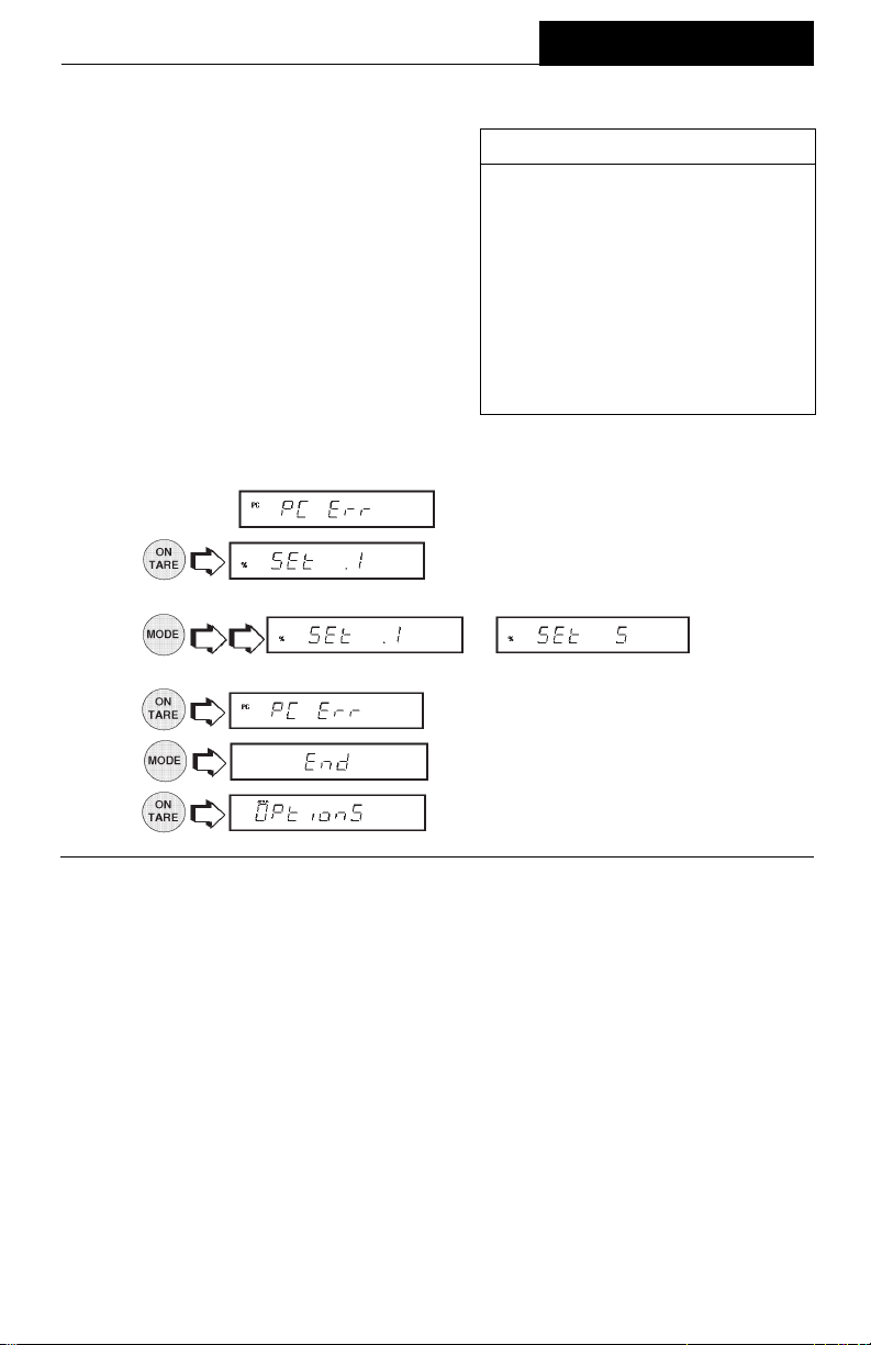
Parts Counting ErrorParts Counting Error
Parts Counting Error
Parts Counting ErrorParts Counting Error
Parts counting Error is enabled only when
the Parts Counting Function is selected.
The parts counting error level is the level
of accuracy you consider acceptable for
parts counting results. The adjacent table
lists error levels that you can choose from.
The default setting is shown in bold type.
EXAMPLE: With 5 Pct selected, 100 parts
on the platform may yield a displayed
count from 95 to 105 parts.
To view, change or disable the PC Error Level:
MENUS
ERROR LEVELSERROR LEVELS
ERROR LEVELS
ERROR LEVELSERROR LEVELS
OFFOFF
OFF
OFFOFF
.1 % ±0.1% acceptable error.
.25 % ±0.25% acceptable error.
.5 % ±0.5% acceptable error.
1 % ±1.0% acceptable error.
2.5 % ±2.5% acceptable error.
5 % ±5.0% acceptable error.
Disables error level limits.Disables error level limits.
Disables error level limits.
Disables error level limits.Disables error level limits.
1. Access the
2.
submenu under the Setup Option submenu.
indicates percentage of acceptable error.
Settings are shown in table.
3.
• • • to change the
percentage error limits,
4.
5.
6.
Check Weighing OptionsCheck Weighing Options
Check Weighing Options
Check Weighing OptionsCheck Weighing Options
when the desired setting is reached.
.
.
Check Weighing is enabled only when the Check Weighing Function is selected. This
feature may be used for check weighing or package weight control in any one of the
available weighing units. When in use, the display will show the relationship between
the load on the pan, and the selected target weight. The bar graph will visibly display
where the weight of the load falls in relationship to the under, acceptable, and over
limits. The balance also displays UNDER, ACCEPT, and OVER messages as
appropriate. The default settings are: Reference = Reference weight, Display =
normal.
Two choices are provided for programming the Reference Weight. One choice is the
use of a mass (package, container, etc,) and the other is a number which can be
entered as a high and low limit.
Three choices are provided for programming the display: normal, none, and sign.
Sample displays are shown on the next page.
49
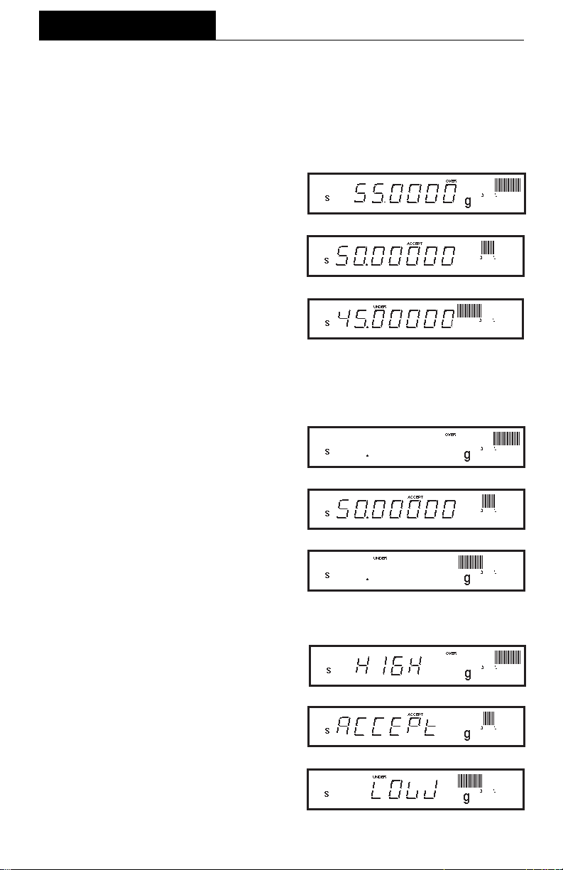
MENUS
SAMPLE DISPLAYSSAMPLE DISPLAYS
SAMPLE DISPLAYS
SAMPLE DISPLAYSSAMPLE DISPLAYS
NOTENOTE
NOTE: Samples of the displays for check weighing are shown as follows using a
NOTENOTE
reference weight of 50 grams. The over limit was set at 55 grams, and the lower limit
was set at 45 grams.
NORMAL DISPLAYSNORMAL DISPLAYS
NORMAL DISPLAYS
NORMAL DISPLAYSNORMAL DISPLAYS
When normal is selected, the display indicates the actual weight.
NONE DISPLAYSNONE DISPLAYS
NONE DISPLAYS
NONE DISPLAYSNONE DISPLAYS
When none is selected, the numeric section of the display is blank if the values
exceed the limits. Numbers appear only
if they are within the limits.
SIGN DISPLAYSSIGN DISPLAYS
SIGN DISPLAYS
SIGN DISPLAYSSIGN DISPLAYS
When sign is selected, the display spells
in words; HIGH, LOW or ACCEPT with no
weight values showing.
50
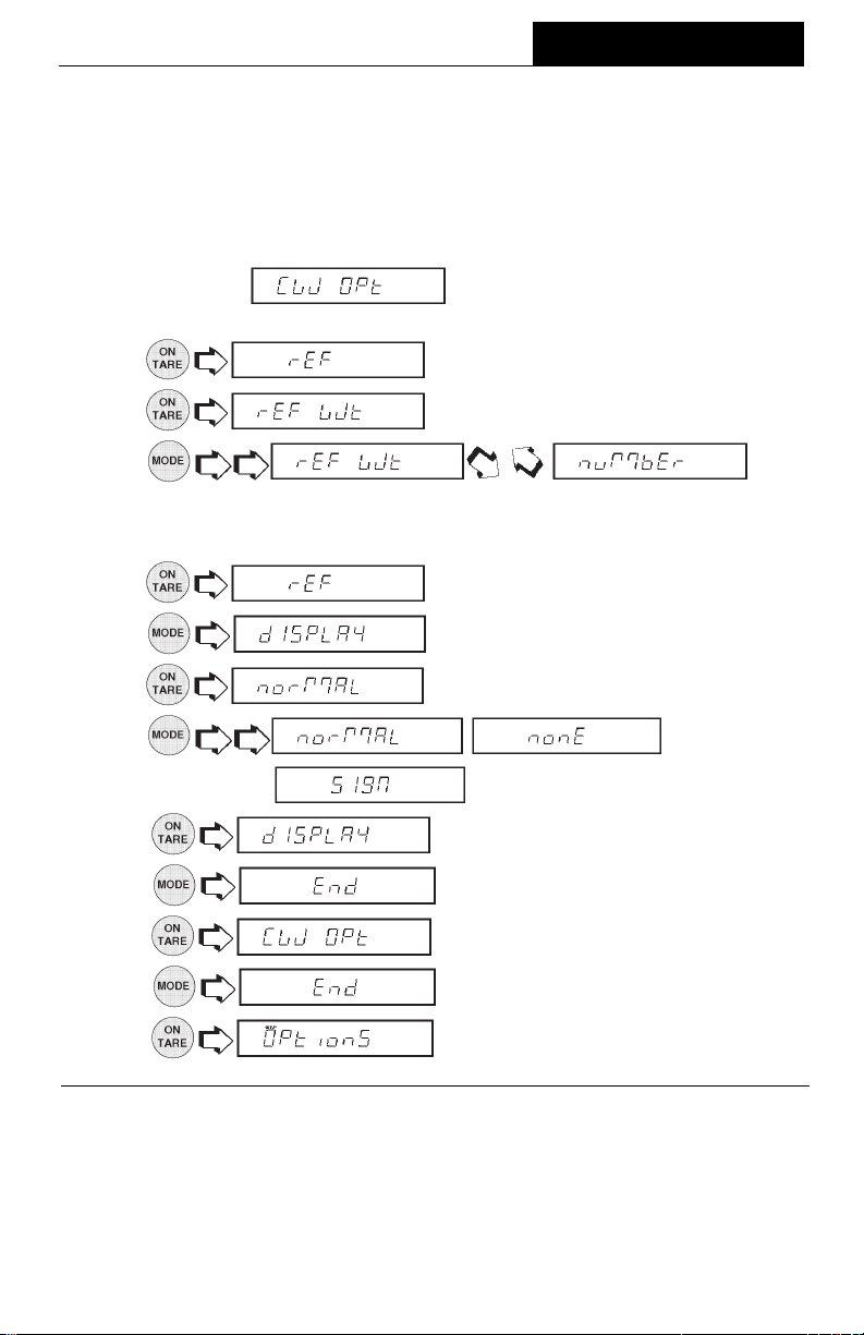
MENUS
Check Weighing Options (Cont.)Check Weighing Options (Cont.)
Check Weighing Options (Cont.)
Check Weighing Options (Cont.)Check Weighing Options (Cont.)
The following procedure describes how to set up the balance for all choices. Before
starting, the Check Weighing option must have been selected under the Functions
submenu.
1. Access the
menu.
2.
3.
4.
If REF WT is selected, a sample reference is used later to set the weight
parameter into the balance. If NUMBER is selected, a number representing the
sample weight has to be entered manually. See section titled Check Weighing.
5.
6.
7.
8. , ,
9. .
10.
submenu under the Setup Options sub
(reference).
(reference weight).
.
.
.
.
.
.
11.
12.
13.
.
.
.
51
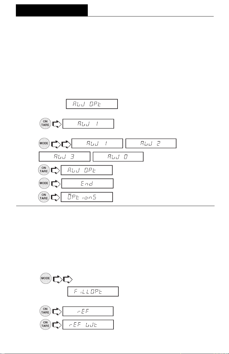
MENUS
Animal Weighing OptionsAnimal Weighing Options
Animal Weighing Options
Animal Weighing OptionsAnimal Weighing Options
Animal Weighing Options is enabled only when Animal Weighing Function is
selected. The balance samples the weight data for a variable sampling interval and
processes the data to filter out the instabilities by the live animal.
The strength of the filtering activity as well as the duration of the sampling period can
be adjusted by selecting one of four AW OPT levels, 0 through 3. 0 is the least amount
of processing, as well as the shortest sampling interval while level 3 is the maximum
processing amount and the longest sampling interval. AW3 should be used for an
active subject. The default setting is AW1.
1. Access the submenu under the Setup Option submenu.
2.
3.
, for desired sensitivity.
4.
5.
6.
Fill OptionFill Option
Fill Option
Fill OptionFill Option
Fill Option provides two choices for a reference weight (similar to check weighing).
Either a mass can be placed on the pan and used as a reference weight or a number
can be entered to establish the weight value. Both methods are used to establish a
reference for a 100% bar graph reading. Target parameter provides two choices, one
is fill to the reference, the other to zero. The following procedure describes how to set
up the balance for all choices. Before starting, the Fill Function must have been
selected.
1. to select the desired weighing unit, g, dwt, oz, etc.
.
, ,
.
.
.
2. Access the submenu under the Setup Options sub
menu.
3.
4.
(reference).
(reference weight).
52

MENUS
Fill Option (Cont.)Fill Option (Cont.)
Fill Option (Cont.)
Fill Option (Cont.)Fill Option (Cont.)
5. .
If REF WT is selected, a sample reference weight is used later to set the
weight parameter into the balance. If NUMBER is selected, a number representing
the desired sample weight has to be entered. Select either REF WT or NUMBER.
6. .
7.
show the normal weight of the object on the pan.
8.
9.
is selected, the balance indicates the weight as a negative number after the
reference is set in the main menu. When anobject is placed on the balance
that weighs exactly what the reference was set to, the display shows zero with
a full bar graph.
10.
11.
12.
13.
14.
TimeTime
Time
TimeTime
Time is a feature which enables the balance to be set to the current time in either U.S.A.
standards (12 hour periods) or European/Military standards (24 hour periods). The
default setting is US Standard. To enter time, proceed as follows:
.
. When target is selected, the balance will
or . When zero
.
.
.
.
.
1. Access the
2. .
3.
4.
5.
submenu which is under the Setup menu.
.
or .
.
53
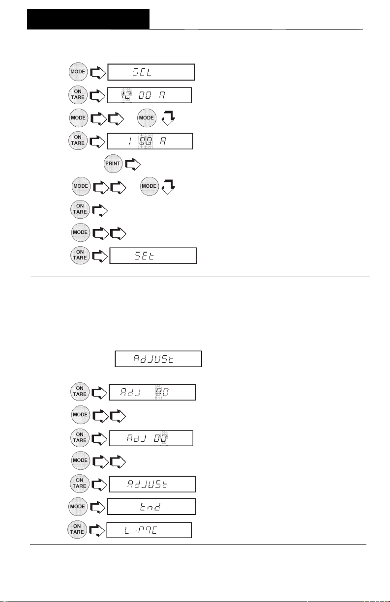
MENUS
Time (Cont.)Time (Cont.)
Time (Cont.)
Time (Cont.)Time (Cont.)
6. .
7.
8. or to change flashing digits to current local hour.
9.
NOTE NOTE
NOTE:
NOTE NOTE
10 or changes minutes display.
11.
12.
13.
AdjustAdjust
Adjust
AdjustAdjust
Adjust is a feature which enables the internal clock of the balance to be corrected
+ or - 59 seconds a day. The internal clock is accurate to within 8 seconds a day. To
enter or subtract time, proceed as follows:
1. Access the
menu.
to accept. AM or PM is flashing, A for AM, P for PM.
will back up display.
to select AM or PM.
first two digits are flashing.
flashes the last two digits.
.
submenu which is under the Time sub
2.
3.
4.
5.
6.
7.
8.
. First digit is flashing.
to change first digit (ten seconds) from 0 to +5 or -5.
, seconds digit is flashing.
to change seconds from 0 to 9.
.
.
.
54

MENUS
DateDate
Date
DateDate
Date is a feature which enables the balance to be set to a U.S.A. date standard or
European date standard. U.S. standard has the month, date followed by the year each
separated by (/) in the printout. The European date standard has the day first, followed
by the month and then the year each separated by a period. The default setting is US
Standard.
1. Access the submenu which is under Setup menu.
2.
3.
4.
5.
6.
7.
8.
for European standard.
9.
10. to change flashing digit.
11.
12.
13.
to change the first flashing digit to current month for US or day
to change year.
.
.
.
.
flashes first two digits.
.
.
.
or .
14.
15.
NOTENOTE
NOTE: At power up, if Time in the GLP submenu is set to ON, the display flashes
NOTENOTE
for about 1.5 seconds to prompt setting of time and date .
.
.
55
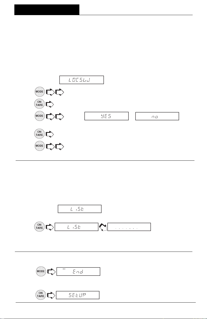
MENUS
LockswitchLockswitch
Lockswitch
LockswitchLockswitch
Lockswitch enables you to lock out one or more menu selections. Each menu can be
individually locked on or off
SetupSetup
Setup and
SetupSetup
appropriate menu and then locked by the switch located under the front of the control
panel. See Menu Lockout Section. Cal Test under Calibration remains functional with
the Lockswitch On or Off. Before performing the lockout procedure, decide which
functions of the balance are to be locked on or off.
PrintPrint
Print menus can be individually locked on or off by selecting the
PrintPrint
after all functions have been set after all functions have been set
after all functions have been set
after all functions have been set after all functions have been set
. The
CalibrationCalibration
Calibration,
CalibrationCalibration
User,User,
User,
User,User,
1. Access the
2.
3.
4.
YES = locked, NO = not locked.YES = locked, NO = not locked.
YES = locked, NO = not locked.
YES = locked, NO = not locked.YES = locked, NO = not locked.
5.
6.
7. To change other menus, repeat steps 2 through 5.
ListList
List
ListList
This submenu can be used to output a listing of current menu settings via the RS232
interface. When selected, all menu settings for the User, Setup and Print menus will
be output either to an external printer or computer. To use this feature, your balance
must be connected to a computer or printer.
1.Access the
2.
indicates a series of dots traveling right to left when the balance is sending
information.
to access either Calibration, User, Setup or Print menus.
to access selected desired menu.
to select or .
to accept.
to change to other menus.
submenu which is under the Setup menu.
submenu under the Setup or Print menus.
. The display
Exit Setup MenuExit Setup Menu
Exit Setup Menu
Exit Setup MenuExit Setup Menu
1. .
NOTENOTE
NOTE: If any Setup parameter is different from previous settings, indicator SETUP in
NOTENOTE
the display flashes while the balance is storing new settings. Proceed with next step.
2.
.
56
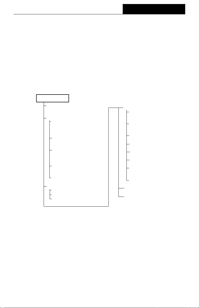
MENUS
PRINT MENUPRINT MENU
PRINT MENU
PRINT MENUPRINT MENU
The Print menu provides a number of options which includes: reset, communications,
good laboratory practices, print options, and list.
in the Print menu to factory default settings.
number of data bits, parity bit type and stop bits.
permits the entering of your own identification number and project number which
shows up on printing.
Print Options
Enables/disables Auto print feature, specifies time
interval for automatic output of displayed data and/or exclude a range of weights from
being output. The following items can be turned on or off: Stable data-only feature,
numeric only or full display data for output, time and date. Items shown in bold type
are default settings. Items shown in italics in the print menu below appear only if the
appropriate Functions are turned on.
PRINT MENUPRINT MENU
PRINT MENU
PRINT MENUPRINT MENU
RESET
YES/NO
COMMUNICATION
Baud
300, 1200,
4800, 9600
Data Bits
77
7 or 8
77
Parity Bit
Odd, Even,
1, 0
Stop Bits
1 or
End, Comm.
GLP
ID #
Project #
End,GLP
24002400
2400,
24002400
None None
None,
None None
2 2
2
2 2
Reset
sets all submenus contained
Communication
GLP
Good laboratory practices
PRINT OPTIONS
Auto Print
Cont, interval,
on stb,
Initialize Auto Print
Interval, non print lo,
non print hi
Stable Data
ON/
Numeric Data
ON/
Time
ON/
Date
ON/
Reference
ON/
End, Print Options
LIST
END, PRINT
specifies baud rate,
offoff
off
offoff
OFFOFF
OFF
OFFOFF
OFFOFF
OFF
OFFOFF
OFFOFF
OFF
OFFOFF
OFFOFF
OFF
OFFOFF
OFFOFF
OFF
OFFOFF
Print Menu ProtectionPrint Menu Protection
Print Menu Protection
Print Menu ProtectionPrint Menu Protection
The Print menu may be locked out to prevent unauthorized personnel from changing
settings. If SAFE is displayed, the Print menu has been locked out. Settings may be
viewed but not changed. To lock out the Print menu or unlock, refer to the section titled
Menu Lock-Out Protection.
57

MENUS
ResetReset
Reset
ResetReset
This submenu enables you to reset
settings shown below. Reset does not appear if the menu has been locked out.
allall
all Print menu selections to the factory default
allall
Function Default
1.
2.
3.
4. .
5.
6.
balance signals a
.
.
.
. If is selected, the
Baud Rate br2400
Data Bits 7 data
Parity none
Stop Bits 2 stop
Auto Print OFF
Auto Print interval 1 second
Non Print Low Limit 0
Non Print High Limit 0
Stable data Only OFF
Numeric Data Only OFF
Time OFF
Date OFF
or .
long beep long beep
long beep
long beep long beep
and all selections reset to factory settings.
CommunicationCommunication
Communication
CommunicationCommunication
The Communication submenu contains submenus which permit the setting of: baud
rates, data bits, parity and stop bits necessary for communications to an external
printer or computer.
Access the submenu under the Print menu..
58

MENUS
Baud RateBaud Rate
Baud Rate
Baud RateBaud Rate
This submenu is used to select the desired baud rate. There are five available baud
rates to choose from: 300, 1200, 2400, 4800 and 9600. The default setting is 2400
baud.
To view or change the baud rate:
1. Access the
2.
3.
, , ,
. Normal baud rate is 2400.
4.
Data BitsData Bits
Data Bits
Data BitsData Bits
To set the number of data bits to 7 or 8:
1. Access the
2.
3.
or .
submenu.
.
, ,
.
submenu.
.
4.
.
59

MENUS
ParityParity
Parity
ParityParity
Parity can be set to Odd, Even or None. The default setting is None. To set parity,
proceed as follows:
1. Access the submenu.
2.
3.
4.
Stop BitsStop Bits
Stop Bits
Stop BitsStop Bits
The number of stop bits can be set to 1 or 2. The default setting is 2. To set stop bits,
proceed as follows:
1. Access the
2. .
3.
4.
Good Laboratory Practice (GLP)Good Laboratory Practice (GLP)
Good Laboratory Practice (GLP)
Good Laboratory Practice (GLP)Good Laboratory Practice (GLP)
, ,
.
.
.
submenu.
or .
.
This submenu enables the storage of an identification number and/or a project
number. When entered into the balance, the identification number and project number
are available when printing. The reason the entries are made under the Print
submenu, is that when legal for trade operation (LFT) is enabled, the Setup submenu
is locked out, leaving the Print submenu free to make entries.
1. Access the
2. .
3.
4.
changes the value of the first digit.
submenu.
first digit is flashing.
60

MENUS
Good Laboratory Practice (GLP) (Cont.)Good Laboratory Practice (GLP) (Cont.)
Good Laboratory Practice (GLP) (Cont.)
Good Laboratory Practice (GLP) (Cont.)Good Laboratory Practice (GLP) (Cont.)
NOTENOTE
NOTE: allows going back to the previous digit for correction.
NOTENOTE
5.
6.
7. Repeat steps 4 through 6 to change all digits.
8.
9.
10.
11.
Print OptionsPrint Options
Print Options
Print OptionsPrint Options
This submenu contains additional features which can be set and include Auto Print,
Initialize Auto Print, Stable Data only, Numeric Data only, Time, Date and Reference
data and Difference. To change any of the above listed options, enter the submenu.
Auto Print FeatureAuto Print Feature
Auto Print Feature
Auto Print FeatureAuto Print Feature
When enabled, the Auto Print feature causes the balance to automatically output
display data in one of three ways: continuously, at user specified time intervals, or upon
stability.
To select one of these Auto Print methods, or to turn the feature off:
accepts value and moves to second digit.
to change next digit.
.
to enter project number.
and repeat steps 3 through 7.
.
1. Access the
2. .
3.
or .
4.
NOTENOTE
NOTE: If you select interval to automatically output data at user specified time
NOTENOTE
intervals, the interval is entered in the Initialize submenu which follows.
submenu.
, ,
.
61

MENUS
InitializeInitialize
Initialize
InitializeInitialize
This submenu allows you to:
• Specify a time interval (in seconds) for automatic output.
• Exclude a range of weights from being output, or specify a range for output, by the
Auto Print feature.
It does not appear on the Print menu if Auto Print is set to OFF. Use the following
procedure to set these features:
1. Access the
submenu under the Print Options submenu.
2. displays if Interval was selected in the Auto
Print submenu and you may continue with step 3. If interval was not selected,
is displayed. Proceed to step 7.
3.
The current interval from
to enter time interval for automatic data output.
to
(in seconds) is displayed.
4.
5.
6.
7.
current value for the low end of the
range is displayed with the first digit
flashing.
8.
start with the first digit (flashing).
Change the value to any number from
-9 to +9. A minus sign will light to
indicate a negative value.
9.
to increase or to decrease the interval number.
.
to enter a range of non printing values.
, the
to change the number,
to accept it and the next digit
To exclude dataTo exclude data
To exclude data
To exclude dataTo exclude data
WITHIN SELECTED RANGE:WITHIN SELECTED RANGE:
WITHIN SELECTED RANGE:
WITHIN SELECTED RANGE:WITHIN SELECTED RANGE:
Example:non-PL=7g, non-PH=11g
To exclude dataTo exclude data
To exclude data
To exclude dataTo exclude data
OUTSIDE SELECTED RANGE:OUTSIDE SELECTED RANGE:
OUTSIDE SELECTED RANGE:
OUTSIDE SELECTED RANGE:OUTSIDE SELECTED RANGE:
Example:non-PL=11g, non-PH=7g
SET non-PL < non-PH
Values <7
Set non-PL > non-PH
Values >7
OR OR
OR >11 will be output.
OR OR
AND AND
AND <11 will be output.
AND AND
will begin flashing.
10.Set all digits in the same manner. If an error is made, to backup to
the desired digit and change it.
62

MENUS
Initialize (Cont.)Initialize (Cont.)
Initialize (Cont.)
Initialize (Cont.)Initialize (Cont.)
11. After the last digit is entered, is displayed again.
12.
13.
14. Repeat steps 8 through 10 to change the numbers as required.
15. After the last digit is entered,
16. .
17.
Print Stable Data OnlyPrint Stable Data Only
Print Stable Data Only
Print Stable Data OnlyPrint Stable Data Only
When enabled, this feature permits only stable display data to be output. To set the
feature ON or OFF, proceed as follows:
1. Access the
2. .
3.
4.
or .
for the high limit.
indicates current high end value.
displayed again.
.
submenu under the Print Options menu.
.
Print Numeric Data OnlyPrint Numeric Data Only
Print Numeric Data Only
Print Numeric Data OnlyPrint Numeric Data Only
This submenu is used to select numeric data only, or full display data for RS232 output.
Set this feature ON to output numeric display data only, or OFF to output full display
data as follows:
1. Access the
2. .
3.
4.
or .
submenu under the Print Options menu.
.
63

MENUS
TimeTime
Time
TimeTime
When the Time function is set ON, allows the balance to output the current time to the
printer. To set the Time feature ON or OFF, proceed as follows:
1. Access the
2. .
3.
4.
DateDate
Date
DateDate
When the Date function is set ON, allows the balance to output the current date to the
printer. To set the Date feature ON or OFF, proceed as follows:
1. Access the
2.
3.
4.
NOTENOTE
NOTE: With Print Time or Date set to ON, if either current Time or Date has not been
NOTENOTE
set in Setup menu, "Set Time/Date !" is sent through the RS232 Interface with each
press of button.
or .
or .
submenu under the Print Options menu
.
submenu under the Print Options menu
.
.
ReferenceReference
Reference
ReferenceReference
When the Reference function is set ON, prints the value of weight used as a reference
in either Check Weighing, Fill Guide, Percent and Parts Counting modes. When set
to Current, the printer prints the current reference immedediately.
1. Access the
2.
3.
.
4.
, or
submenu under the Print Options menu
.
.
64
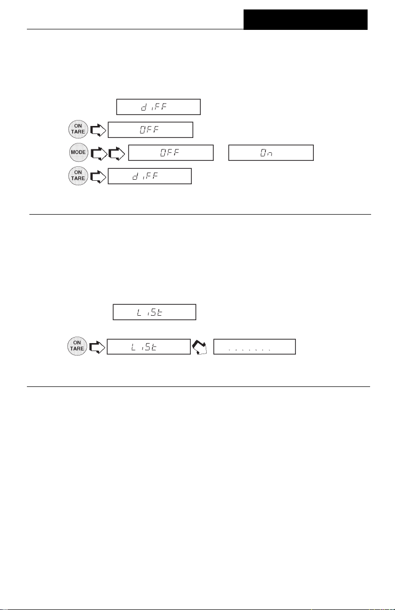
MENUS
DifferenceDifference
Difference
DifferenceDifference
Difference data is only output to the printer when Check Weighing or Fill GuideTM mode
was selected.
1. Access the
2.
3.
4.
ListList
List
ListList
This submenu can be used to output a listing of current menu settings via the RS232
interface. When selected, all menu settings for the User, Setup and Print menus will
be output either to an external printer or computer. To use this feature, your balance
must be connected to a computer or printer.
1.Access the submenu under the Setup or Print menus.
2.
cates a series of dots traveling right to left when the balance is sending
information.
or .
submenu under the Print Options menu
.
.
The display indi-
65

MAINTENANCE
CARE AND MAINTENANCECARE AND MAINTENANCE
CARE AND MAINTENANCE
CARE AND MAINTENANCECARE AND MAINTENANCE
To keep the balance operating properly, the housing and platform should be kept clean
and free from foreign material. If necessary, a cloth dampened with a mild detergent
may be used. Keep calibration masses in a safe dry place.
TROUBLESHOOTINGTROUBLESHOOTING
TROUBLESHOOTING
TROUBLESHOOTINGTROUBLESHOOTING
SYMPTOM
Unit will not turn on.
Incorrect weight reading.
Cannot display weight in
desired unit or cannot
access desired weighing
mode.
Unable to store menu
settings/changes.
RS232 interface not
working.
PROBABLE CAUSE(S)
Power cord not plugged in
or properly connected to
balance.
Balance was not re-zeroed
before weighing.
Balance not properly
calibrated.
Desired unit/mode not
set to ON in Unit Selection
of Setup menu.
End not being used to exit
menus.
Print menu settings not
properly set up.
Cable connections.
REMEDY
Check power cord
connections.
Press with no
weight on the pan, then
weigh item.
Recalibrate correctly.
See Unit Selection section
of Setup menu.
You MUST use End to exit
menus and save settings.
Verify interface settings in
Print menu correspond to
those of peripheral device.
Check cable connections.
Random segments
displayed or display
locks up.
Unable to change
settings.
Unstable readings.
Error message display.
Microprocessor locks up.
Lock set ON.
(LFT set ON)
Vibration on table surface.
66
Turn power off, then turn
on again. If condition
persists, unit must be
serviced.
Set Lock switch to OFF.
Place balance on a stable
surface or change
averaging level.
See Error Codes list.

MAINTENANCE
Error Codes ListError Codes List
Error Codes List
Error Codes ListError Codes List
The following list describes the various error codes and which can appear on the
display and the suggested remedy.
Data ErrorsData Errors
Data Errors
Data ErrorsData Errors
0.0 Internal data errors. If error persists, the balance must be serviced.
1.0 Internal data errors. If error persists, the balance must be serviced.
Tare ErrorsTare Errors
Tare Errors
Tare ErrorsTare Errors
2.0 Illegal tare operation or balance is unable to stabilize within time limit after
taring. Environment is too hostile or balance needs recalibration.
Calibration ErrorsCalibration Errors
Calibration Errors
Calibration ErrorsCalibration Errors
3.0 Incorrect or no calibration weight used for User calibration. Recalibrate with
correct weights.
5.0 Auto calibration failed. Environment is to hostile, recalibrate the balance.
RS232 ErrorsRS232 Errors
RS232 Errors
RS232 ErrorsRS232 Errors
4.4 RS232 buffer is full (if installed). May occur if no printer or computer is
connected to the interface. To clear buffer, turn balance off or enter Print menu
and select END.
4.5 Function is disabled by the Lock switch.
User ErrorsUser Errors
User Errors
User ErrorsUser Errors
7.0 User entry out of range (custom factor, non-pH, non-pL, etc...)
7.1 Bad percent (%) mode, sample too low.
7.2 Number outside of display capacity.
Over-Under Load ErrorsOver-Under Load Errors
Over-Under Load Errors
Over-Under Load ErrorsOver-Under Load Errors
8.0 Hardware error causing an internal weight signal which is too low. Check if
platform or platform support is off. If not, the balance must be serviced.
8.2 Internal power on error. Turn the power off, then turn it back on.
8.3 Hardware error caused by an internal weight signal which is too high. Check
load on the platform which may be excessive. If error persists, the balance must
be serviced.
67

MAINTENANCE
Error Codes List (Cont.)Error Codes List (Cont.)
Error Codes List (Cont.)
Error Codes List (Cont.)Error Codes List (Cont.)
System ErrorsSystem Errors
System Errors
System ErrorsSystem Errors
5.1 thrrough 5.9
System errors. Turn the power off, then turn it back on. If error persists, have
the balance serviced.
Checksum ErrorsChecksum Errors
Checksum Errors
Checksum ErrorsChecksum Errors
9.7 Invalid setup data checksum. Check Setup, User, and Print menus settings. if
possible, try to enter menus and exit using END to restore menu settings. May
be caused by a faulty component, or in rare cases, a severe static charge. If
error persists, balance must be serviced.
68

MAINTENANCE
SERVICE INFORMATIONSERVICE INFORMATION
SERVICE INFORMATION
SERVICE INFORMATIONSERVICE INFORMATION
If the Troubleshooting section does not resolve or describe your problem, you will need
to contact an authorized Ohaus Service Agent. For Service assistance in the United
States, please call Ohaus Corporation toll-free at (800) 526-0659. An Ohaus Product
Service Specialist will be available to help you.
REPLACEMENT PARTSREPLACEMENT PARTS
REPLACEMENT PARTS
REPLACEMENT PARTSREPLACEMENT PARTS
OHAUS
Part No.
Power Cords:
U.S. 120 V ac 6569-00
European 220 V ac 76212-00
European 240 Vac 76448-00
Pan (AP110, AP210 and AP250 modes) 9773-00
Pan (AP310 models) 9773-01
Pan Shield 9773-02
Pan Ring 9773-03
Leveling Foot 9773-04
In-Service Cover 9773-78
Fuse (160 mA/250 V for all models) 90167-42
ACCESSORIESACCESSORIES
ACCESSORIES
ACCESSORIESACCESSORIES
Anti-Theft Device 77401-00
Density Determination Kit 77402-00
Storage Cover 9773-79
Calibration Masses - ASTM Class 1 Tolerance:
100 g 49015-11
200 g 49025-11
69
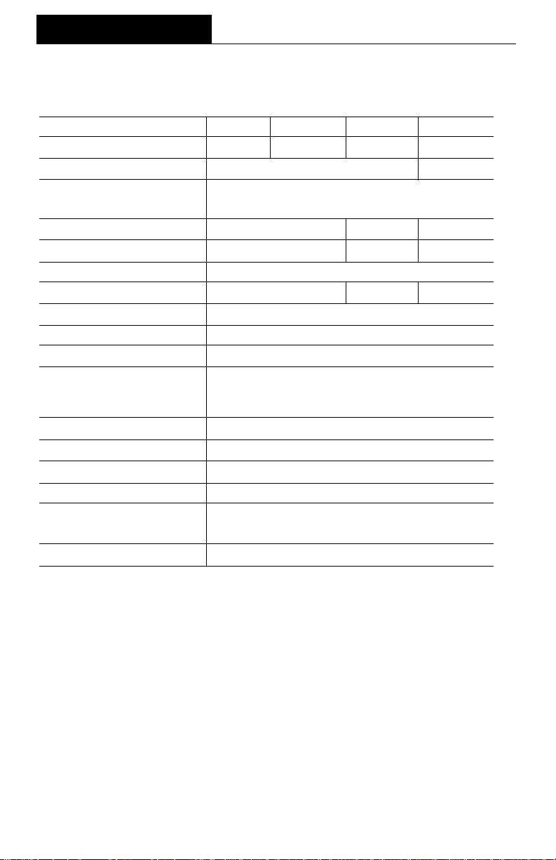
MAINTENANCE
SPECIFICATIONSSPECIFICATIONS
SPECIFICATIONS
SPECIFICATIONSSPECIFICATIONS
MODELMODEL
MODEL
MODELMODEL
Capacity (g) 110 210 310 52/210
Readability (mg) 0.1 0.01/0.1
Weighing modes g, oz, ct, dwt, (3) taels, oz t, gn, mommes,
Repeatability (Std. dev.) (mg) 0.1 0.2 0.02/0.1
Linearity (mg) ±0.2 ±0.5 ±0.03/0.2
Tare range To capacity by subtraction
Stabilization time (sec) 4 8 12/5
Sensitivity drift (10 - 30 °C) ±2 ppm/ °C
Operating temperature range 50° to 104°F/10° to 40°C
Calibration Motorized internal and manual external
Internal calibration weights Stainless steel - measured to ±0.1 mg at an
Power requirements 100, 120, 220, 240 V ac, 50/60Hz
Display (in/cm) Vacuum fluorescent (0.5/1.3 high)
Pan size (in/cm) 3.5/9
Free height above pan (in/cm) 9.5/24
Dimensions 7.7 x 12.2 x 15.7
(WxHxD) (in/cm) 19.5 x 31 x 40
Net weight (lb/kg) 22.5/10.2
AP110AP110
AP110
AP110AP110
1 custom unit, parts counting, percent weighing,
AP210AP210
AP210
AP210AP210
air density of 1.2 mg/cm
on virtual mass with density 8.0 g/cm
AP310AP310
AP310
AP310AP310
3
3
AP250DAP250D
AP250D
AP250DAP250D
70

LIMITED WARRANTYLIMITED WARRANTY
LIMITED WARRANTY
LIMITED WARRANTYLIMITED WARRANTY
Ohaus products are warranted against defects in materials and workmanship from the
date of delivery through the duration of the warranty period. During the warranty period
Ohaus will repair, or, at its option, replace any component(s) that proves to be
defective at no charge, provided that the product is returned, freight prepaid, to Ohaus.
This warranty does not apply if the product has been damaged by accident or misuse,
exposed to radioactive or corrosive materials, has foreign material penetrating to the
inside of the product, or as a result of service or modification by other than Ohaus. The
warranty period shall begin at the date of installation, or three months from shipment
to the buyer, whichever occurs first. A properly completed Warranty Registration Card
must be received by Ohaus within 30 days from date of purchase to initiate coverage
under the warranty. No other express or implied warranty is given by Ohaus
Corporation. Ohaus Corporation shall not be liable for any consequential damages.
As warranty legislation differs from state to state and country to country, please contact
Ohaus or your local Ohaus dealer for further details.
71

Ohaus Corporation
29 Hanover Road,
Florham Park, NJ 07932, USA
Tel: (973) 377-9000,
Fax: (973) 593-0359
With offices worldwide.
P/N 78209-01 R1099 © Ohaus Corporation 1995, 1999, all rights reserved.
72


TABLE OF CONTENTS
UNPACKING.........................................................................................................6
INSTALLATION.....................................................................................................7
Environment ...............................................................................................7
Weigh Below Hook.....................................................................................7
Leveling the Balance..................................................................................8
Installing the Pan Assembly .......................................................................8
In-Service Cover.........................................................................................8
Connecting Power......................................................................................9
Spare Fuse.................................................................................................9
Self Test .....................................................................................................9
Turning the Display ON and OFF.............................................................10
INITIAL CALIBRATION.......................................................................................11
OPERATION.......................................................................................................12
Auto Range (Model AP25OD Only)..........................................................12
Selecting a Weighing Unit or Mode .......................................................... 12
Weighing ..................................................................................................12
Taring.......................................................................................................13
Parts Counting..........................................................................................14
Percent Weighing.....................................................................................17
Printing.....................................................................................................20
USING MENUS TO CONFIGURE THE BALANCE.............................................21
CALIBRATION MENU AND PROCEDURE ........................................................22
Auto Calibration........................................................................................23
External Calibration..................................................................................23
SETUP MENU.....................................................................................................26
Reset to Original Factory Settings............................................................27
Unit Selection ...........................................................................................28
Averaging Level........................................................................................29
Stability Range .........................................................................................29
Auto-Zero .................................................................................................30
Custom Unit Conversion Factor................................................................31
4

Parts Counting Error Level.......................................................................33
Parts Counting Alternate Display..............................................................34
Percent Weighing Alternate Display.........................................................35
Menu Lockout...........................................................................................36
List............................................................................................................37
End........................................................................................................... 37
PRINT MENU......................................................................................................38
Reset to Original Factory Settings............................................................39
Baud Rate ................................................................................................40
Data Bits.................................................................................................. 40
Parity........................................................................................................41
Stop Bits...................................................................................................41
Auto Print Feature ....................................................................................42
Auto Print Time Interval and Non Printing Weight Values ........................42
Print Stable Data Only..............................................................................45
Print Numeric Data Only...........................................................................45
List............................................................................................................46
End........................................................................................................... 46
MENU LOCK-OUT PROTECTION......................................................................47
RS-232 INTERFACE...........................................................................................47
Hardware..................................................................................................48
Output Formats.........................................................................................48
RS-232 Commands..................................................................................48
RS-232 COMMAND TABLE.....................................................................49
TROUBLESHOOTING........................................................................................51
Error Codes..............................................................................................52
SPECIFICATIONS .............................................................................................. 53
CARE AND MAINTENANCE...............................................................................54
SERVICE INFORMATION ..................................................................................54
REPLACEMENT PARTS ....................................................................................54
ACCESSORIES ..................................................................................................54
LIMITED WARRANTY.........................................................................................55
5


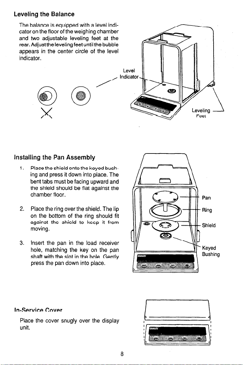

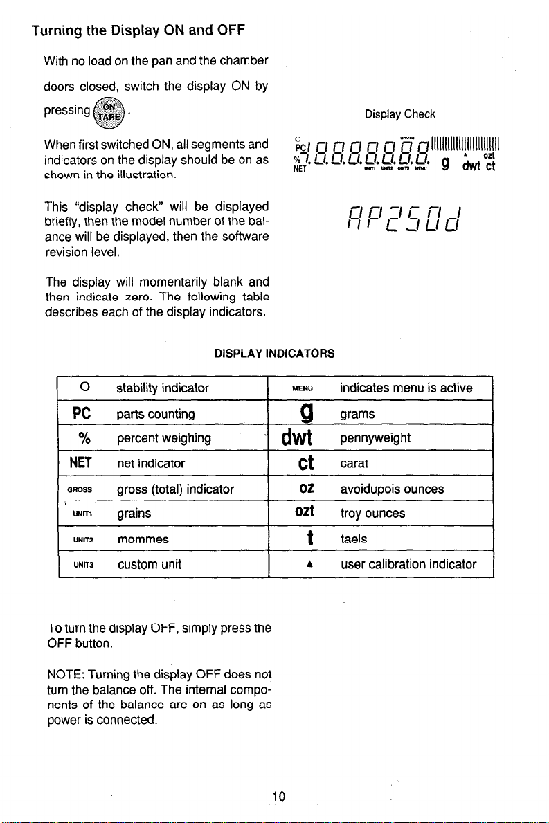
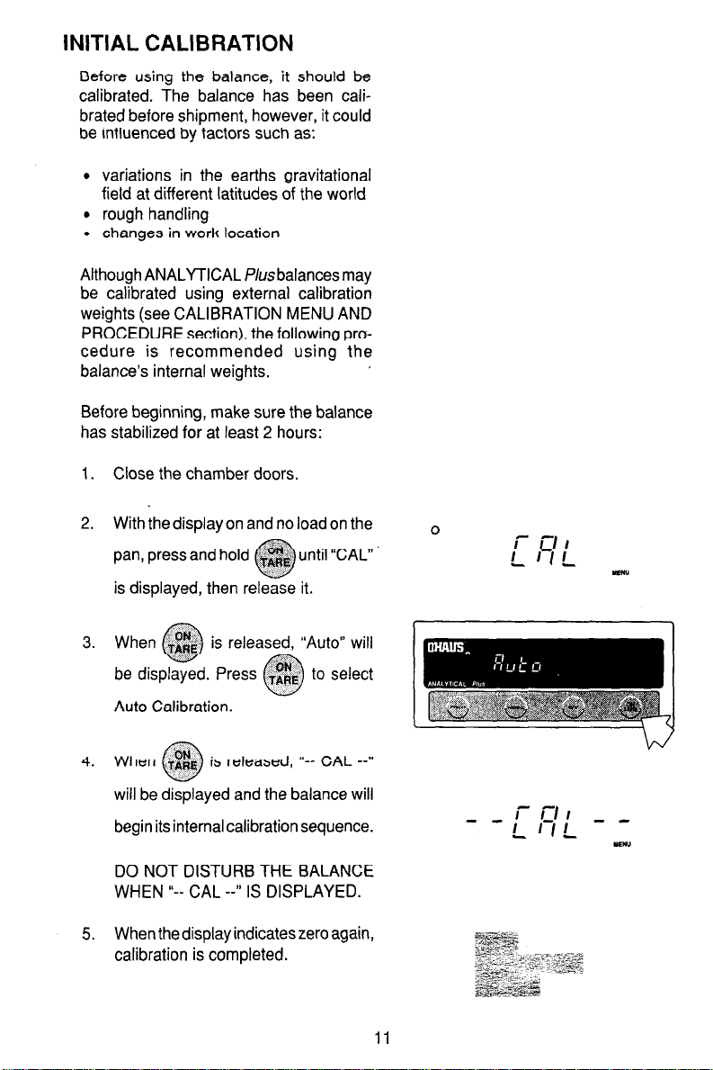
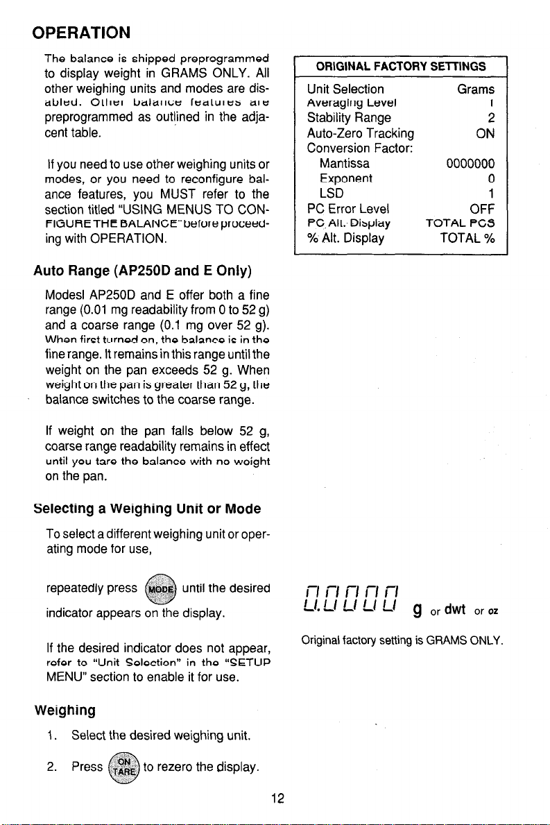
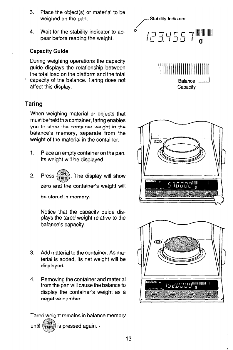
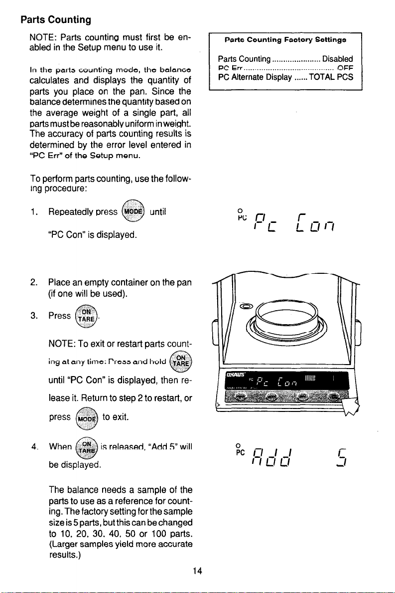
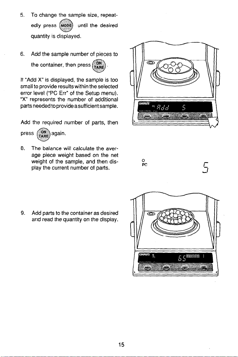
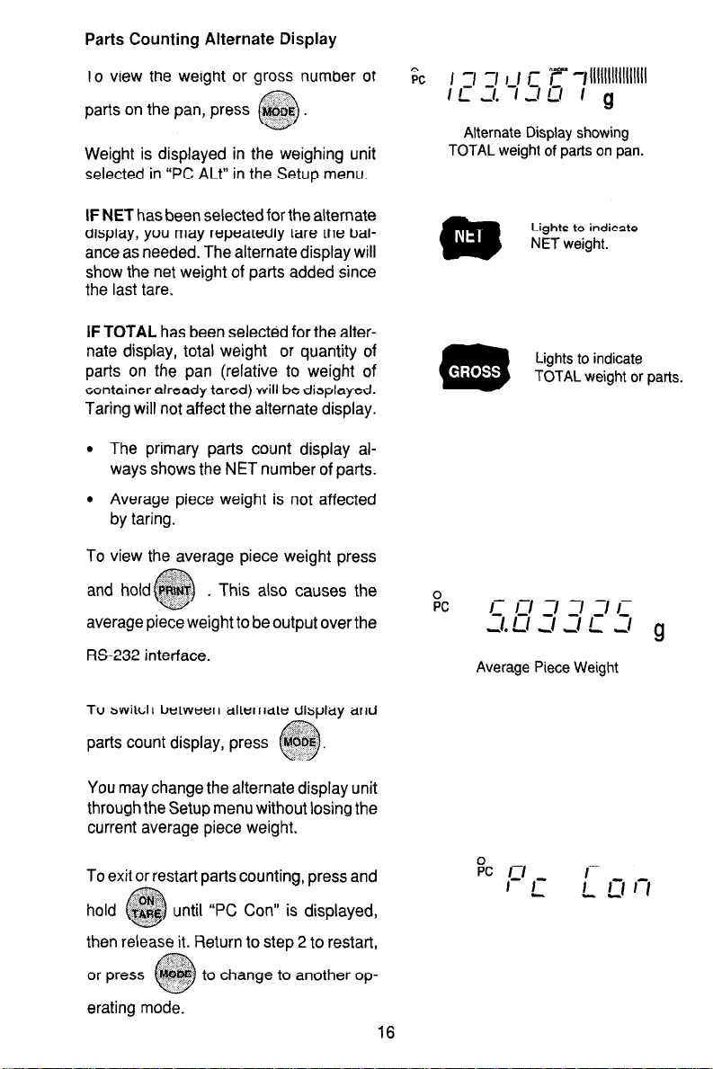
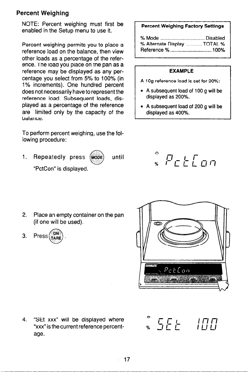


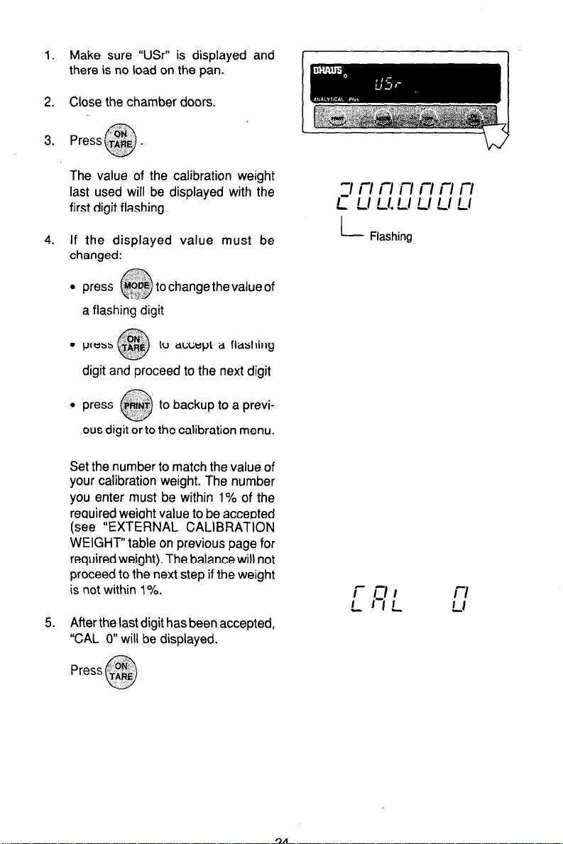
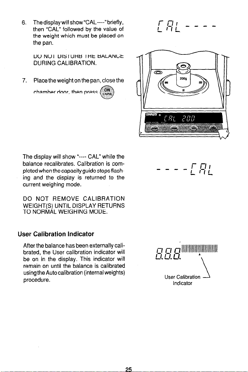
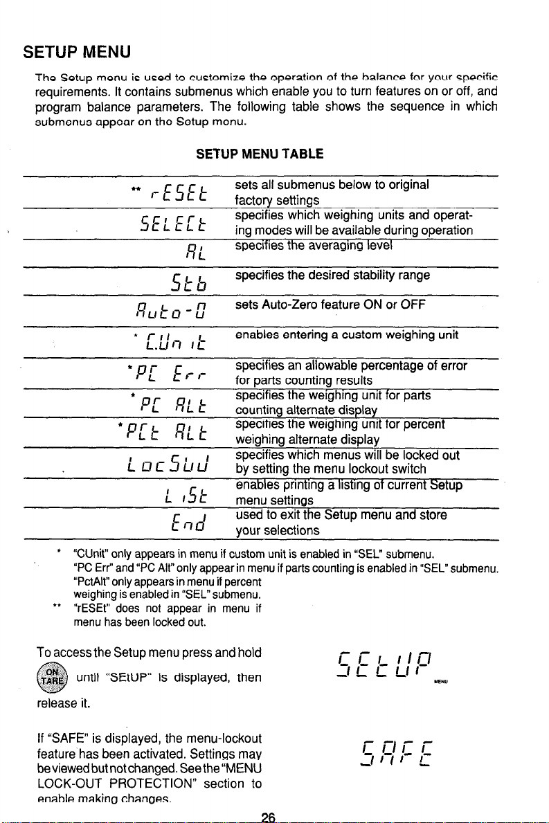


 Loading...