

Page 1

a-AB23EC
Bench Conductivity Meter
Instruction Manual
Find Quality Products Online at: [email protected]
www.GlobalTestSupply.com
Page 2

Page 3

a-AB23EC Bench Conductivity Meter EN-1
Table of Contents
1. INTRODUCTION .......................................................................................................... 2
1.1. SAFETY PRECAUTIONS .............................................................................................................. 2
1.2. INTENDED USE ....................................................................................................................... 3
1.3. DISPLAY AND CONTROLS .......................................................................................................... 4
2. INSTALLATION ............................................................................................................ 6
2.1 INSTALL THE STAND-ALONE ELECTRODE HOLDER ............................................................................. 6
2.2 INSTALLING THE POWER ADAPTER ............................................................................................... 7
2.3 CONNECT THE CONDUCTIVITY ELECTRODES .................................................................................... 7
3. SETUP ......................................................................................................................... 8
3.1 SET TEMPERATURE UNIT, MTC TEMPERATURE AND TEMPERATURE CORRECTION COEFFICIENT ................... 8
3.2 SET TDS FACTOR .................................................................................................................... 8
4. OPERATION ................................................................................................................ 9
4.1 CALIBRATION ......................................................................................................................... 9
4.1.1 Select a standard solution ............................................................................................ 9
4.1.2 Perform a calibration ................................................................................................... 9
4.2 SAMPLE MEASUREMENT ......................................................................................................... 10
4.2.1 TDS and Salinity measurement .................................................................................. 11
4.3 MEMORY ........................................................................................................................... 11
4.3.1 Store a reading .......................................................................................................... 11
4.3.2 Recall a memory ........................................................................................................ 11
4.3.3 Clear a memory .......................................................................................................... 11
5. MAINTENANCE ......................................................................................................... 12
5.1 ERROR MESSAGE .................................................................................................................. 12
5.2 METER MAINTENANCE ........................................................................................................... 12
5.3 ELECTRODE MAINTENANCE ..................................................................................................... 12
5.4 CLEANING ........................................................................................................................... 13
5.5 SELF-DIAGNOSIS ................................................................................................................... 13
5.6 RECOVER FACTORY SETTINGS ................................................................................................... 13
6. TECHNICAL DATA ...................................................................................................... 14
6.1 SPECIFICATIONS .................................................................................................................... 14
6.2 DIMENSIONS ....................................................................................................................... 16
7. APPENDIX ................................................................................................................. 17
7.1 CONDUCTIVITY STANDARDS ..................................................................................................... 17
7.2 EXAMPLES OF TEMPERATURE COEFFICIENTS (Α-VALUE) .................................................................. 17
7.3 CONDUCTIVITY TO TDS CONVERSION FACTORS ............................................................................ 17
8. COMPLIANCE ............................................................................................................ 18
Find Quality Products Online at: [email protected]
www.GlobalTestSupply.com
Page 4

EN-2 a-AB23EC Bench Conductivity Meter
1. INTRODUCTION
This manual contains installation, operation and maintenance instructions for a-AB23EC
bench conductivity meter. Please read it completely before installation and operation.
1.1. Safety precautions
Definition of Signal Warnings and Symbols
Safety notes are marked with signal words and warning symbols. These show safety
issues and warnings. Ignoring the safety notes may lead to personal injury, damage to
the instrument, malfunctions and false results.
WARNING
For a hazardous situation with medium risk, possibly resulting in severe
injuries or death if not avoided.
CAUTION
For a hazardous situation with low risk, resulting in damage to the device
or the property or in loss of data, or minor or medium injuries if not
avoided.
ATTENTION
For important information about the product. May lead to equipment
damage if not avoided.
NOTE
For useful information about the product.
Warning Symbols
General
hazard
Explosion
hazard
Electrical shock
hazard
Safety Precautions
CAUTION: Read all safety warnings before installing, making connections, or
servicing this equipment. Failure to comply with these warnings could result
in personal injury and/or property damage. Retain all instructions for future
reference.
Before connecting power, verify that the AC adapter’s input voltage range
and plug type are compatible with the local AC mains power supply.
Do not position the equipment such that it is difficult to reach the power
connection.
Make sure that the power cord does not pose a potential obstacle or
tripping hazard.
The equipment is for indoor use only.
Do not operate the equipment in wet, hazardous or unstable
environments.
When using chemicals and solvents, comply with the instructions of the
chemical producer and the general lab safety rules.
Do not allow liquids to enter the equipment.
Disconnect the equipment from the power supply when cleaning.
Service should only be performed by authorized personnel.
Find Quality Products Online at: [email protected]
www.GlobalTestSupply.com
Page 5

a-AB23EC Bench Conductivity Meter EN-3
WARNING: When using chemicals and solvents, comply with the instructions
of the producer and the general lab safety rules.
WARNING: Never work in an environment subject to explosion hazards! The
housing of the instrument is not gas tight. (Explosion hazard due to spark
formation, corrosion caused by the ingress of gases)
WARNING: Electrical shock hazards exist within the housing. The housing
should only be opened by authorized and qualified personnel. Remove all
power connections to the unit before opening.
1.2. Intended use
This instrument is intended for use in laboratories, pharmacies, schools, businesses and
light industry. It must only be used for measuring the parameters described in these
operating instructions. Any other type of use and operation beyond the limits of technical
specifications, without written consent from OHAUS, is considered as not intended. This
instrument complies with current industry standards and the recognized safety
regulations; however, it can constitute a hazard in use. If the instrument is not used
according to these operating instructions, the intended protection provided by the
instrument may be impaired.
Find Quality Products Online at: [email protected]
www.GlobalTestSupply.com
Page 6

EN-4 a-AB23EC Bench Conductivity Meter
1.3. Display and Controls
Figure 1-1 Display
1. Calibration icon: blinks when calibration is in progress.
2. Measurement icon: blinks when measurement or calibration is in progress.
3. Auto endpoint icon ; Continuous reading icon .
4. Setup icon: shows when the meter is in setup mode.
5. Standard solution icon: displays the standard solution for calibration.
6. Measurement mode icon: displays measurement mode, Conductivity, TDS and
Salinity.
7. Auto temperature compensation icon ATC; Manual temperature compensation
icon MTC; Reference temperature icon R.Temp.
8. Memory number icon MR; Error index icon Err; Store icon .
Controls
Figure 1-2 Control Panel
1 2 3
4
5 7 8
6
Find Quality Products Online at: [email protected]
www.GlobalTestSupply.com
Page 7
a-AB23EC Bench Conductivity Meter EN-5
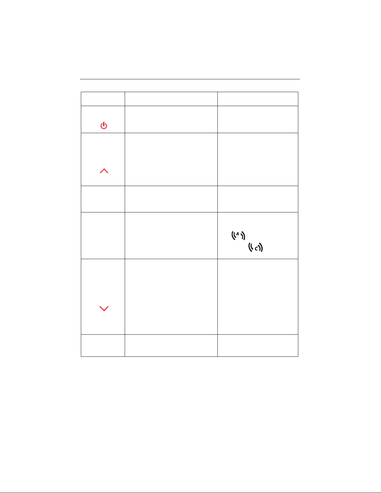
Button
Press & release
Press & hold
for 3 seconds
Exit
Turns on the meter
Cancels the current
measurement
Exits calibration
Turns off the meter
Store
Recall
Stores the current
measurement result
When checking the stored
measurement results, moves
to the previous record.
When setting parameters,
increases the setting value or
displays the previous option.
Recalls stored measurement
results
Mode
TDS-F
Switches between EC, TDS and
SAL mode.
Sets TDS-F value
(Ranging from 0.4 to 1.00, and
the default is 0.5.)
Read/Enter
Auto - Stop
Starts or ends measurement
Ends the current
measurement in the auto
endpoint mode and shows the
result
Confirms settings and stores
setting parameters
Switches between auto and
continuous endpoint mode
Auto
Continuous
Standard
Temp
Selects standard solution
When checking the stored
measurement results, moves
to the next record.
When setting parameters,
decreases the setting value or
displays the next option.
Enters temperature setting:
1. Selects temperature unit.
2. Sets MTC temperature.
(The defaut is 25°C.)
3. Sets reference
temperature.
4. Sets temperature
correction coefficient
value. (Ranging from 0 to
10, and the default is
2%/degree)
Cal
Cal.Data
Starts calibration
Recalls the latest calibration
data
Find Quality Products Online at: [email protected]
www.GlobalTestSupply.com
Page 8

EN-6 a-AB23EC Bench Conductivity Meter
2. INSTALLATION
2.1 Install the stand-alone electrode holder
1. Screw the metal rod into the base.
2. Hold the button located at the bottom of the upper electrode arm, and pass the
arm through the metal rod.
3. Release the button at the height you want to finish the installation.
Find Quality Products Online at: [email protected]
www.GlobalTestSupply.com
Page 9
a-AB23EC Bench Conductivity Meter EN-7
2.2 Installing the power adapter
Insert the proper adapter clip into the power adapter slot.
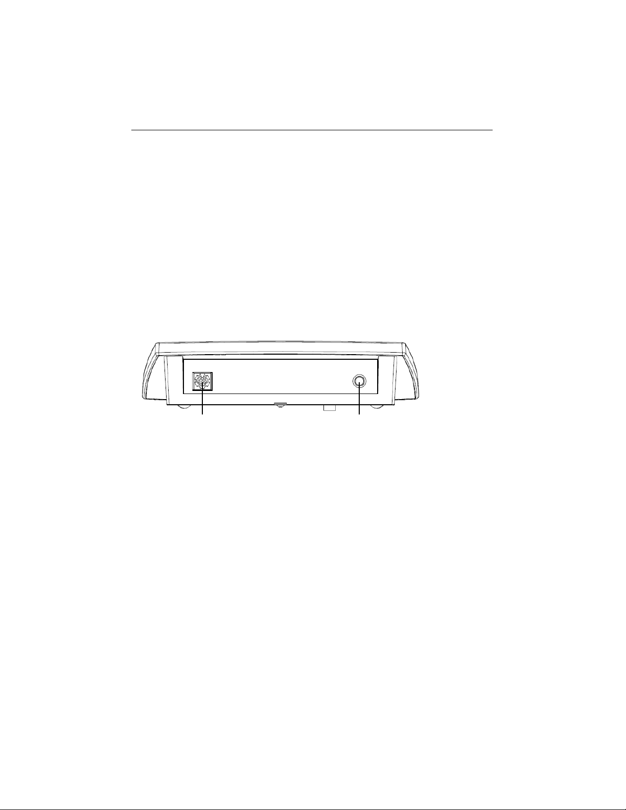
2.3 Connect the conductivity electrodes
There is one socket “COND.” for conductivity electrode.
Note: If you use a STCON3 electrode, please keep the plastic shield and make sure the
4 metal rings on the electrode are totally submerged in the standard solution.
DC.
COND.
Find Quality Products Online at: [email protected]
www.GlobalTestSupply.com
Page 10

EN-8 a-AB23EC Bench Conductivity Meter
3. SETUP
3.1 Set temperature unit, MTC temperature and
temperature correction coefficient
1. Press the Exit button to turn the meter on.
2. Long press the Temp. button to enter setting.
3. The symbol °C is flashing.
4. Press the or button to switch between °C and °F.
5. Press the Read/Enter button to confirm your selection.
6. Continue to set the MTC temperature by using or button to adjust.
7. Press the Read/Enter button to confirm the setting.
8. Continue to select the Reference temperature by using or button to adjust.
9. Press the Read/Enter button to confirm the setting.
10. Continue to set the temperature correction coefficient by using or button to
adjust.
11. Press the Read/Enter button to confirm the setting.
Note:
1. The default MTC temperature value is 25°C (77°F).
2. °C = 5/9 (°F - 32).
3.2 Set TDS factor
To set TDS factor:
1. Long press the TDS-F button.
2. The default value 0.50 is flashing.
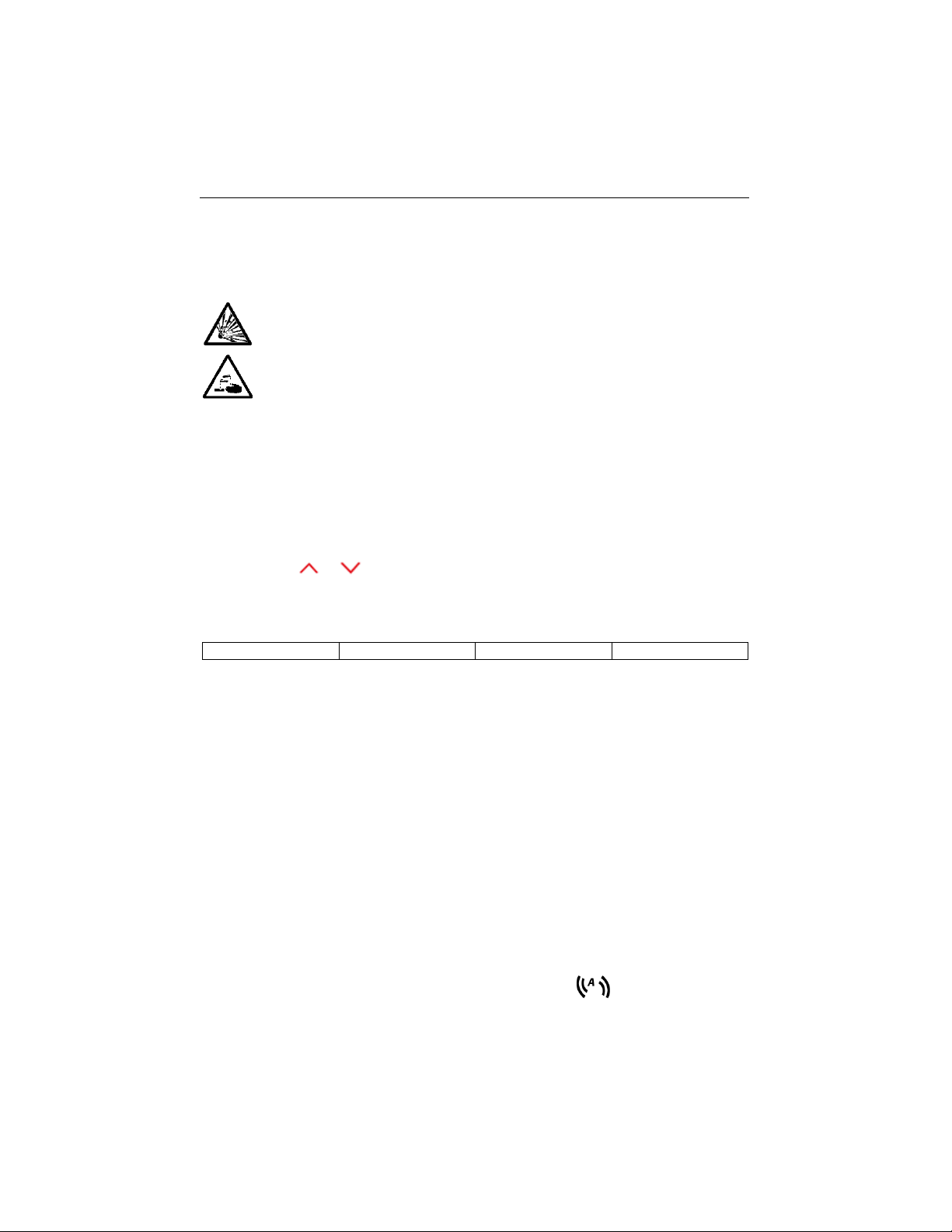
3. Press the or button to adjust the value.
4. Press the Read/Enter button to confirm the setting.
Find Quality Products Online at: [email protected]
www.GlobalTestSupply.com
Page 11
a-AB23EC Bench Conductivity Meter EN-9
4. OPERATION
The first time you use the conductivity electrode, it should be calibrated before taking
any measurement.
WARNING Do not operate the equipment in hazardous environments. The
equipment is not explosion protected.
WARNING When using chemicals and solvents, comply with the instructions
of the chemical producer and the general lab safety rules.
4.1 Calibration
When using the conductivity meter, you have to select a standard solution for
calibration.
4.1.1 Select a standard solution
To do this:
1. Press the Standard button.
2. Press the or button to switch between the 4 standard solutions.
3. Press the Read/Enter button to confirm the setting or press the Exit button to
return to the measurement screen.
The 4 predefined standard solutions are:
10 µS/cm
84 µS/cm
1413 µS/cm
12.88 m S/cm
The meter will then display the selected
standard solution.
Check figure 4-1 as an example. The display
shows 1413 at the right corner of the screen.
Tables for automatic temperature compensation are programmed in the meter for each
standard (see the appendix).
4.1.2 Perform a calibration
When performing a calibration, Ohaus recommends using Auto End Point Mode. After
powering the meter on, be sure the top of the screen shows to ensure the meter
is in Auto End point Mode.
Figure 4-1 Standard solution
Find Quality Products Online at: [email protected]
www.GlobalTestSupply.com
Page 12
EN-10 a-AB23EC Bench Conductivity Meter
4.1.2.1 Auto or Continuous End Point Mode
Press and hold the Auto-Stop button to change the End Point Mode.
When in Continuous Mode, to manually reach a calibration value, you need to
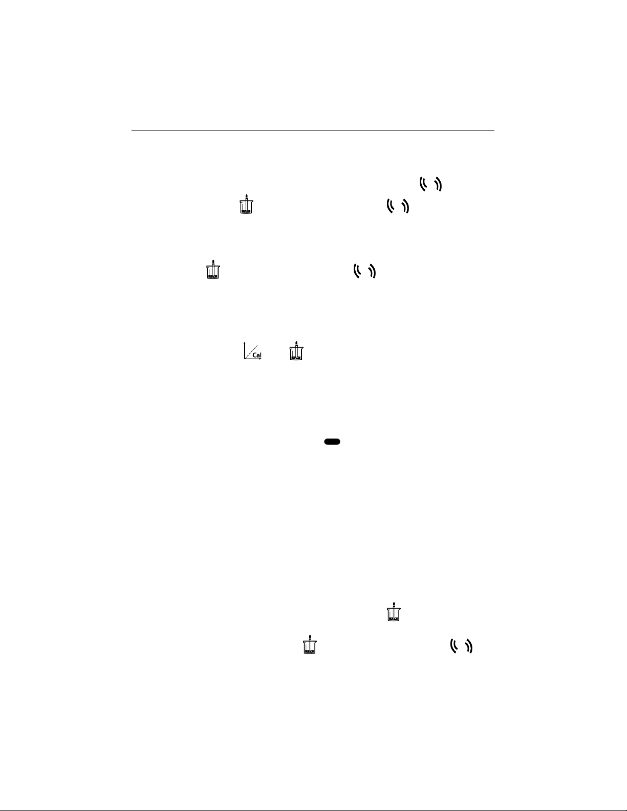
press the Auto-Stop button when reading is stable and displays . Then the
reading freezes and blinks 2 times then disappears; blinks 3 times and
freezes on the display.
When in Auto End Point Mode, the meter determines when the reading is stable
then displays and locks the reading or calibration value automatically, the reading
freezes and blinks 2 times then disappears; blinks 3 times and freezes
on the display.
4.1.2.2 Calibration
Place the conductivity sensor in the selected calibration standard, wait for 10-15
seconds, then:
1 Press the Cal button. and appear on the top of the screen, and both are
blinking during calibration.
Note:
a) Calibration starts with the Auto End Point Mode.
b) Pressing the Auto-Stop button during the calibration can end the process.
2 The meter reaches endpoint automatically according to the preselected auto-
endpoint mode. The screen will display the calibration K value. The calibrated
standard solution value will be marked in .
The calibration is finished, the calibration result will be stored automatically.
Note:
To ensure the most accurate conductivity readings, you should verify your cell constant
with a standard solution before measurement and recalibrate if necessary. Always use
fresh standards.
For STCON3 the normal cell constant range is 1.50 – 2.00. (e.g. 1.71 /cm) if the cell
constant is outside the range due to an improper calibration, you may need to recover
factory settings, then repeat calibration.
4.2 Sample measurement
Place the conductivity sensor in the sample, wait for 10-15 seconds, then:
1 Press the Read/Enter button to start the measurement, appears on the
display and is blinking during measurement.
2 When the meter reaches endpoint ( blinks 2 times then disappears;
blinks 3 times and freezes on the display.), it will display the conductivity.
Find Quality Products Online at: [email protected]
www.GlobalTestSupply.com
Page 13

a-AB23EC Bench Conductivity Meter EN-11
Note: in Continuous End Point Mode, you need to press the Auto-Stop button to
manually end the measurement.
Stability criterion for conductivity measurement: The sensor input signal of the
meter may not change by more than 0.4% from the measured average conductivity of
the probe in 6 seconds.
When measuring low-range conductivity, a flow-through cell is required to isolate the air.
4.2.1 TDS and Salinity measurement
1 Press the Mode button to switch between conductivity, TDS and SAL
measurement modes.
2 Follow the same procedure as for conductivity measurement.
4.3 Memory
4.3.1 Store a reading
The meter can store up to 99 endpoint results and 1 calibration result.
Press the Store button when the measurement reaches endpoint. flashes 3 times
and after that the measurement result has been stored.
If you press the Store button when M99 is displayed, FUL displays to indicate the
memory is full. To store further data you will have to clear the memory. (See the
following Clear the memory section for details).
4.3.2 Recall a memory
1. Press and hold the Recall button to recall the stored values from memory when
the current measurement reaches endpoint.
2. Press the or button to scroll through the stored results. R01 to R99
indicates which result is being displayed.
3. Press the Exit button to exit.
4.3.3 Clear a memory
1. Press the or button to scroll through the stored results until “CL” appears.
2. Press the Read/Enter button. CLr appears and blinks.
3. There are now 2 options:
Press the Read/Enter button to confirm the deletion of all the stored data.
Press the Exit button to return to the measurement mode without deleting the
memory.
Find Quality Products Online at: [email protected]
www.GlobalTestSupply.com
Page 14
EN-12 a-AB23EC Bench Conductivity Meter
5. MAINTENANCE
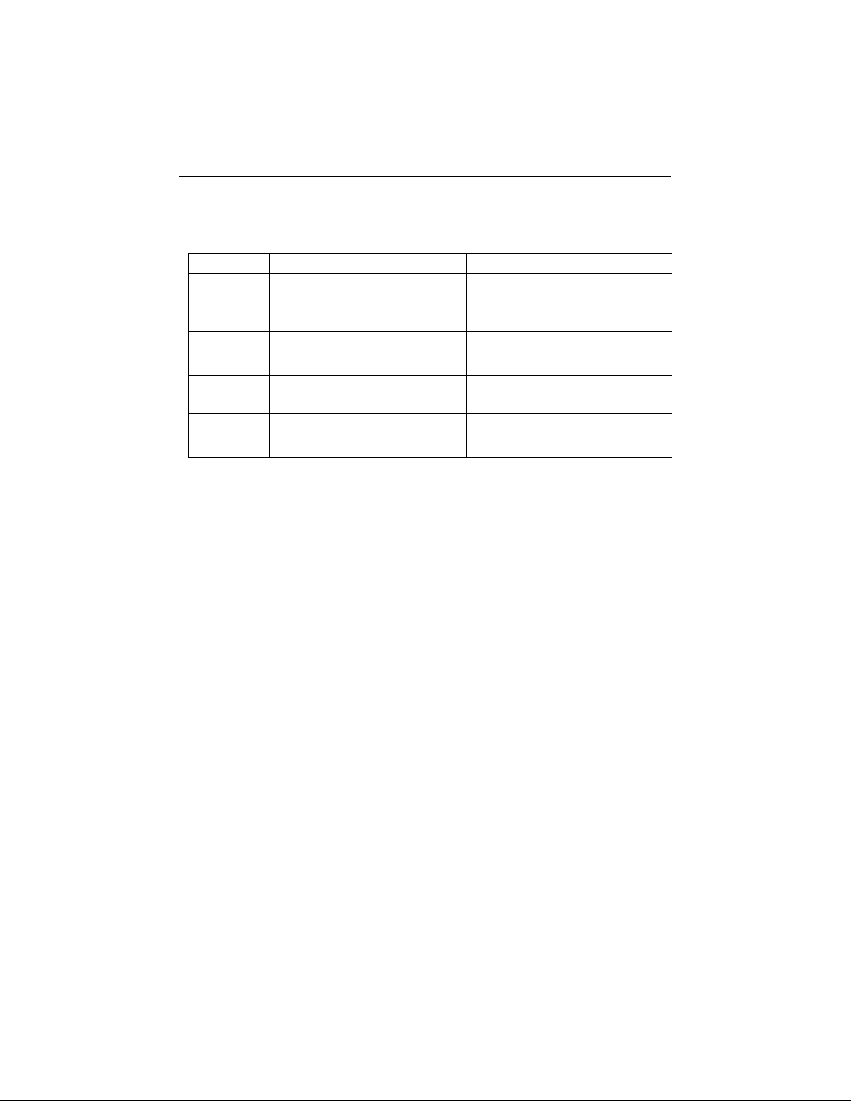
5.1 Error message
Error Code
Possible Cause
Possible Solution
Error 1
Self-diagnosis failed
Repeat the self-diagnosis
procedure and make sure that you
finish pressing all six buttons
within two minutes.
Error 2
Measured values out of range
Check if the electrode is properly
connected and placed in the
sample solution
Error 3
Measured standard temperature
out of range (0 ... 35 °C)
Keep the standard temperature
within the range for calibration
Error 9
The current data set has already
been stored once
An endpoint reading can only be
stored once. Perform a new
measurement to store.
Note: If an error happens, the meter will also beep 3 times to alert.
If the troubleshooting section does not resolve your problem, contact an OHAUS technical
support agent. For assistance in the United States, call toll-free 1-800-526-0659 between
8:00 AM and 5:00 PM Eastern Standard Time. An OHAUS Technical Support Specialist
5.2 Meter maintenance
Never unscrew the two halves of the housing!
The meter does not require any maintenance other than occasional wipe with a damp
cloth and the replacement of depleted batteries.
The housing is made of acrylonitrile butadiene styrene (ABS). This material is attacked
by some organic solvents, such as toluene, xylene and methyl ethyl ketone (MEK). Any
spillage should be immediately wiped off.
5.3 Electrode maintenance
Conductivity Cell Storage
Conductivity cells can be stored in distilled or deionized water between measurements.
For overnight storage or long-term storage, conductivity cells should be thoroughly
rinsed and stored dry.
Find Quality Products Online at: [email protected]
www.GlobalTestSupply.com
Page 15
a-AB23EC Bench Conductivity Meter EN-13
Conductivity Probe Maintenance
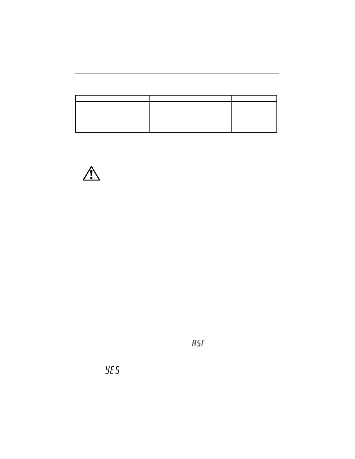
Cleaning Recommendations:
Contaminant
Cleaning Solution
Cleaning Time
Water soluble contaminants
Rinse with deionized water
No limit
Lubricants and oils
Soak in warm water about 60°C
and liquid detergent
10 to 30 minutes
Lime or hydroxide coating
Soak in 10% acetic acid or 10%
hydrochloric acid
10 to 30 minutes
5.4 Cleaning
The housing may be cleaned with a cloth dampened with a mild detergent if necessary.
5.5 Self-diagnosis
When the meter is on, press and hold the Read/Enter button and the Cal button
simultaneously until the meter displays the full screen. Each icon blinks one after the
other.
This way you may check whether all icons are correctly shown. The next step is to
check that the buttons are functioning correctly. This requires user interaction.
When b blinks, six icons (including b) are displayed.
Press the six buttons in any order. Each time you press a button, an icon disappears
from the screen. Continue to press the other buttons until all the icons have
disappeared.
When the self-diagnosis has been completed successfully, PAS appears. If selfdiagnosis fails, error message Err 1 appears.
Note: You have to finish pressing all six buttons within 2 minutes, otherwise Err 1
appears and you will have to repeat the procedure.
5.6 Recover factory settings
When the meter is off, press and hold the Read/Enter button, Cal button and Exit
button together for 3 seconds, the screen displays and blinks, this means
“Reset”. There are 2 options:
Press the Read/Enter button to reset factory settings (MTC, slope and offset, etc.),
display then restart the meter.
WARNING: Electric Shock Hazard. Disconnect the equipment from
the power supply before cleaning.
Make sure that no liquid enters the interior of the instrument.
Attention: Do not use solvents, harsh chemicals, ammonia or
abrasive cleaning agents.
Find Quality Products Online at: [email protected]
www.GlobalTestSupply.com
Page 16

EN-14 a-AB23EC Bench Conductivity Meter
Or press the Exit button to quit the setting, display then turn off the meter.
6. TECHNICAL DATA
6.1 Specifications
Equipment Ratings:
Indoor use only
Altitude:
2000m
Operating temperature:
5 to 40°C
Humidity:
Maximum relative humidity 80% for temperatures up to
31 °C decreasing linearly to 50% relative humidity at 40°C.
Electrical supply:
12VDC, 0.1A. (For use with certified or approved power supply,
which must have a SELV and limited energy output.)
Voltage fluctuations:
Mains supply voltage fluctuations up to ±10% of the
nominal voltage.
Overvoltage category
(Installation category):
II
Pollution degree:
2
Benchtop Meter Model
a-AB23EC
Display Type
5" segment LCD with backlight
Measurement Channels
1
Measurement End-point
Modes
Auto-stop, Continuous
Datalog for measurement
99 sets
Datalog for calibration
Last calibration
Keypad
Membrane
Conductivity input
Mini-Din
Temperature input
Cinch, NTC 30 kΩ
Power Supply
Power input: 100-240V~ 200mA 50-60Hz 12-18VA
Power output: 12 VDC 0.5A
Net Weight
2.5 kg
Gross Weight
2.8 kg
Transportation Size
370 x 268 x 251 mm
Find Quality Products Online at: [email protected]
www.GlobalTestSupply.com
Page 17
a-AB23EC Bench Conductivity Meter EN-15
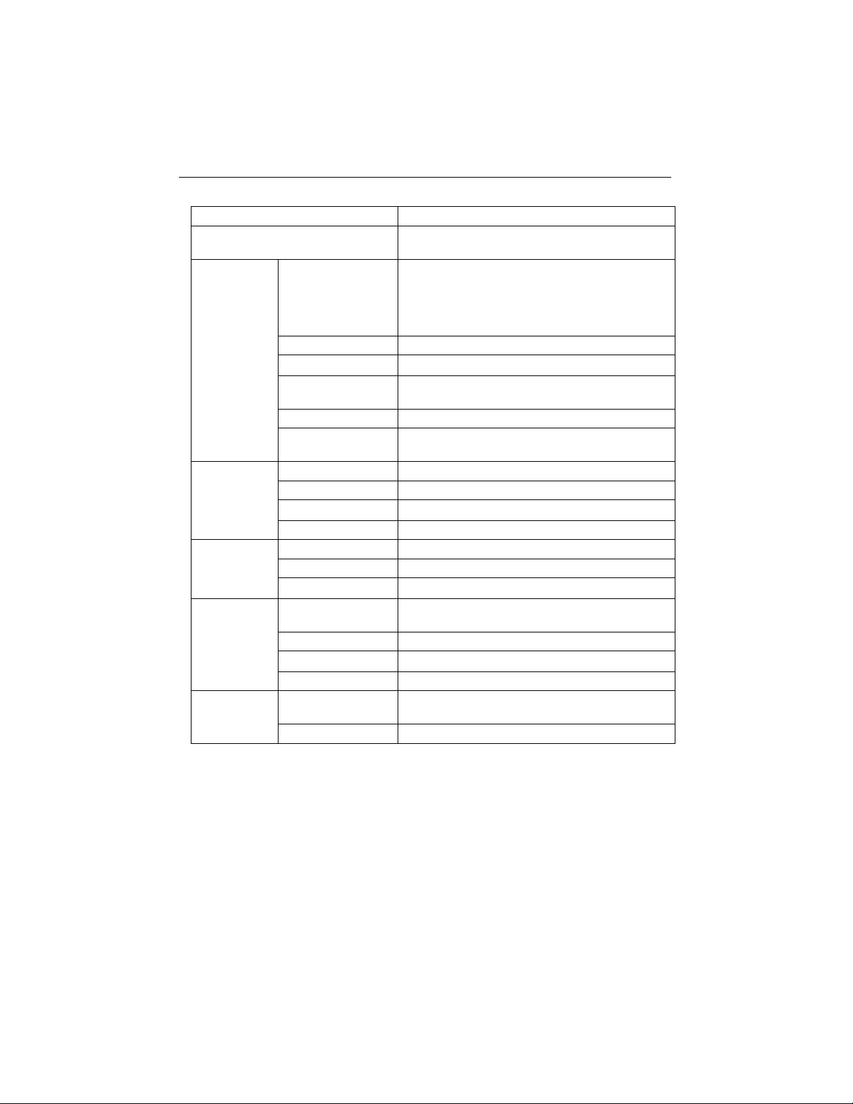
Conductivity Meter Model
a-AB23EC
Measurement Channels
Conductivity/TDS/Salinity/Resistivity with
temperature
Conductivity
Measuring Range
0.01 μS/cm to 19.99 μS/cm
20 μS/cm to 199.9 μS/cm
200 μS/cm to 1999 μS/cm
2.00 mS/cm to 19.99 mS/cm
20.0 mS/cm to 199.9 mS/cm
Resolution
0.01 μS/cm minimum; auto ranging
Accuracy
± 1 % Reading ± 3 LSD
Reference
Temperature
20 °C, 25 °C
Cell Constants
0.08 to 2.0 cm-1
Temperature
Compensation
Linear (0 to 10.0%/ºC), off
TDS
Measuring range
0.1 mg/L to 199.9 g/L
Resolution
0.01 mg/L minimum, auto ranging
Accuracy
± 1 % Reading ± 3 LSD
TDS Factor Range
Linear, 0.04 to 10.00, default 0.5
Practical
Salinity
Measuring range
0 to 99.9 psu
Resolution
0.01 psu minimum, auto ranging
Accuracy
± 1 % Reading ± 3 LSD
Temperature
Measuring Range
0.0 to 100.0 °C,
32.0 °F to 212.0 °F
Resolution
0.1 °C, 0.1 °F
Accuracy
± 0.5 °C, ±0.5 °F
Calibration
No
Calibration
Calibration points
1 point cell constant calibration; 4 buffers
available(10, 84, 1413 μS/cm, 12.88mS/cm)
Calibration mode
Linear
Find Quality Products Online at: [email protected]
www.GlobalTestSupply.com
Page 18
EN-16 a-AB23EC Bench Conductivity Meter
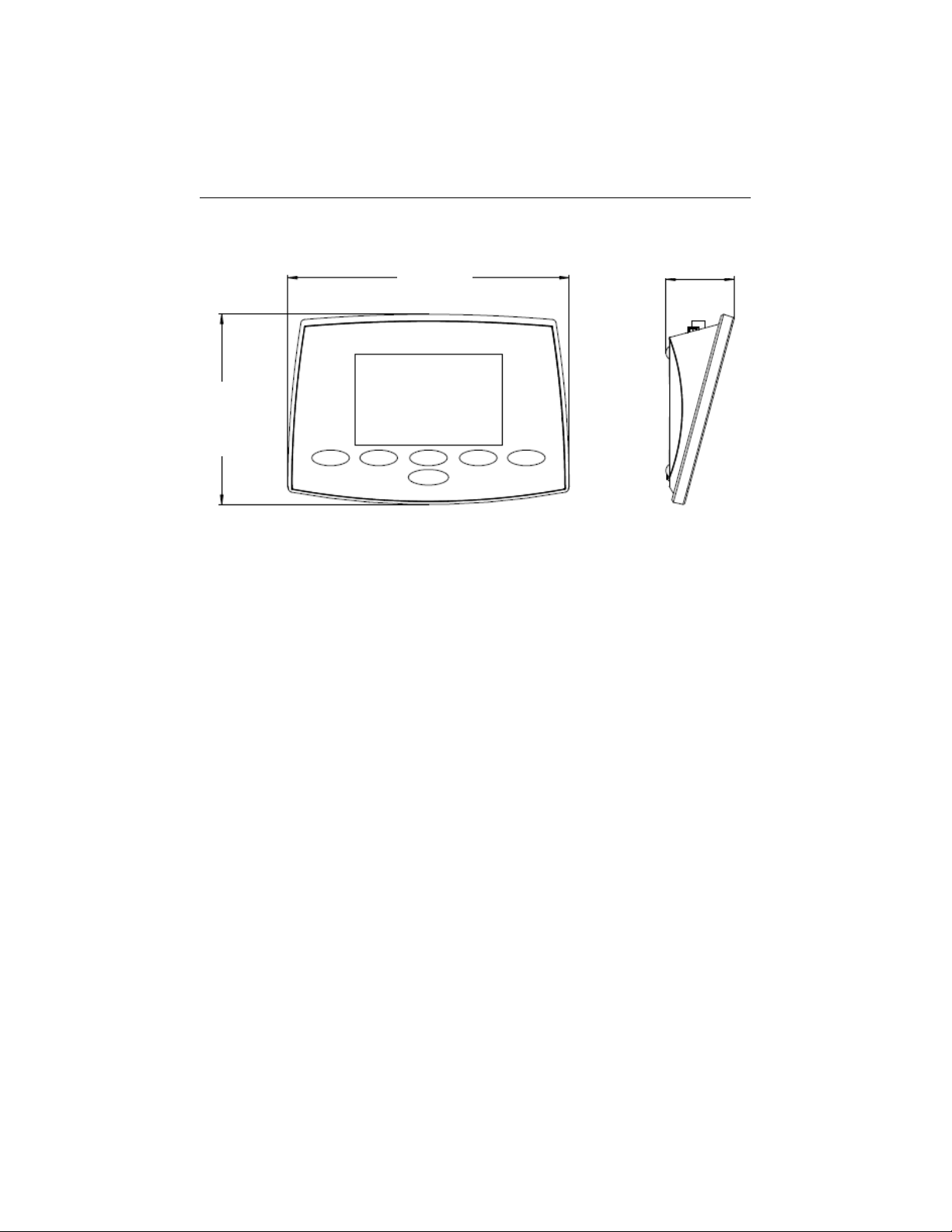
6.2 Dimensions
Figure 6-1 Dimensions
210 mm
142 mm
51 mm
Find Quality Products Online at: [email protected]
www.GlobalTestSupply.com
Page 19
a-AB23EC Bench Conductivity Meter EN-17
7. Appendix
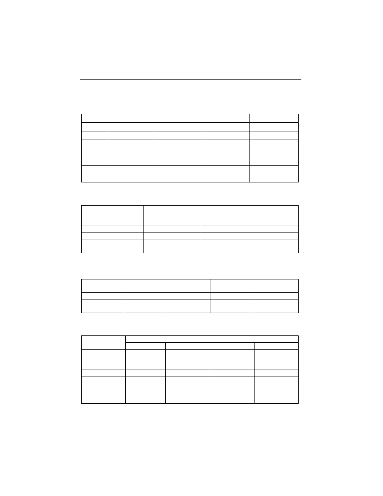
7.1 Conductivity standards
T(°C)
10 μS/cm
84 μS/cm
1413 μS/cm
12.88 mS/cm
5
6.1 μS/cm
53 μS/cm
896 μS/cm
8.22 mS/cm
10
7.0 μS/cm
60 μS/cm
1020 μS/cm
9.33 mS/cm
15
8.0 μS/cm
68 μS/cm
1147 μS/cm
10.48 mS/cm
20
9.0 μS/cm
76 μS/cm
1278 μS/cm
11.67 mS/cm
25
10.0 μS/cm
84 μS/cm
1413 μS/cm
12.88 mS/cm
30
11.0 μS/cm
92 μS/cm
1552 μS/cm
14.12 mS/cm
35
12.1 μS/cm
101 μS/cm
1667 μS/cm
15.39 mS/cm
7.2 Examples of temperature coefficients (α-value)
Substance at 25 °C
Concentration [%]
Temperature coefficient α [%/°C]
HCl
10
1.56
KCl
10
1.88
CH3COOH
10
1.69
NaCl
10
2.14
H2SO4
10
1.28
HF
1.5
7.20
α-coefficients of conductivity standards for a calculation to reference temperature of
25°C
Standard
Measurement
temp.: 15°C
Measurement
temp.: 20°C
Measurement
temp.: 30°C
Measurement
temp.: 35°C
84 μS/cm
1.95
1.95
1.95
2.01
1413 μS/cm
1.94
1.94
1.94
1.99
12.88 mS/cm
1.90
1.89
1.91
1.95
7.3 Conductivity to TDS conversion factors
Conductivity
At 25 °C
TDS KCl
TDS NaCl
ppm value
Factor
ppm value
Factor
84 μS
40.38
0.5048
38.04
0.4755
447 μS
225.6
0.5047
215.5
0.4822
1413 μS
744.7
0.527
702.1
0.4969
1500 μS
757.1
0.5047
737.1
0.4914
8974 μS
5101
0.5685
4487
0.5000
12.88 μS
7447
0.5782
7230
0.5613
15 μS
8759
0.5839
8532
0.5688
80 mS
52.168
0.6521
48.384
0.6048
Find Quality Products Online at: [email protected]
www.GlobalTestSupply.com
Page 20
EN-18 a-AB23EC Bench Conductivity Meter
8. COMPLIANCE
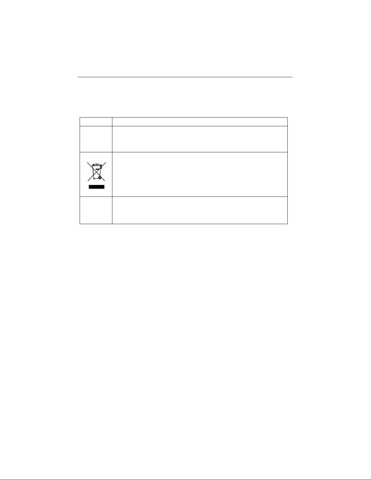
Compliance to the following standards is indicated by the corresponding mark on the
product.
Mark
Standard
This product complies with the applicable harmonized standards of
EU Directives 2011/65/EU (RoHS), 2014/30/EU (EMC), 2014/35/EU
(LVD). The EU Declaration of Conformity is available online at
This product complies with the EU Directive 2012/19/EU (WEEE).
Please dispose of this product in accordance with local regulations at
the collecting point specified for electrical and electronic equipment.
EN 61326-1
ISED Canada Compliance Statement:
CAN ICES-003(A) / NMB-003(A)
ISO 9001 Registration
The management system governing the production of this product is ISO 9001 certified.
Find Quality Products Online at: [email protected]
www.GlobalTestSupply.com
Page 21

a-AB23EC Bench Conductivity Meter EN-19
FCC Supplier Declaration of Conformity
Unintentional Radiator per 47CFR Part B
Trade Name: OHAUS CORPORATION
Model or Family identification: Aquasercher a-AB
FCC Compliance Statement:
Note: This equipment has been tested and found to comply with the limits for a Class A
digital device, pursuant to part 15 of the FCC Rules. These limits are designed to provide
reasonable protection against harmful interference when the equipment is operated in a
commercial environment. This equipment generates, uses, and can radiate radio frequency
energy and, if not installed and used in accordance with the instruction manual, may cause
harmful interference to radio communications. Operation of this equipment in a residential
area is likely to cause harmful interference in which case the user will be required to correct
the interference at his own expense.
Changes or modifications not expressly approved by the party responsible for compliance
could void the user’s authority to operate the equipment.
Find Quality Products Online at: [email protected]
www.GlobalTestSupply.com
Page 22

 Loading...