

Page 1
LD-3 PRO VERSIONLD-3 PRO VERSION
Page 2
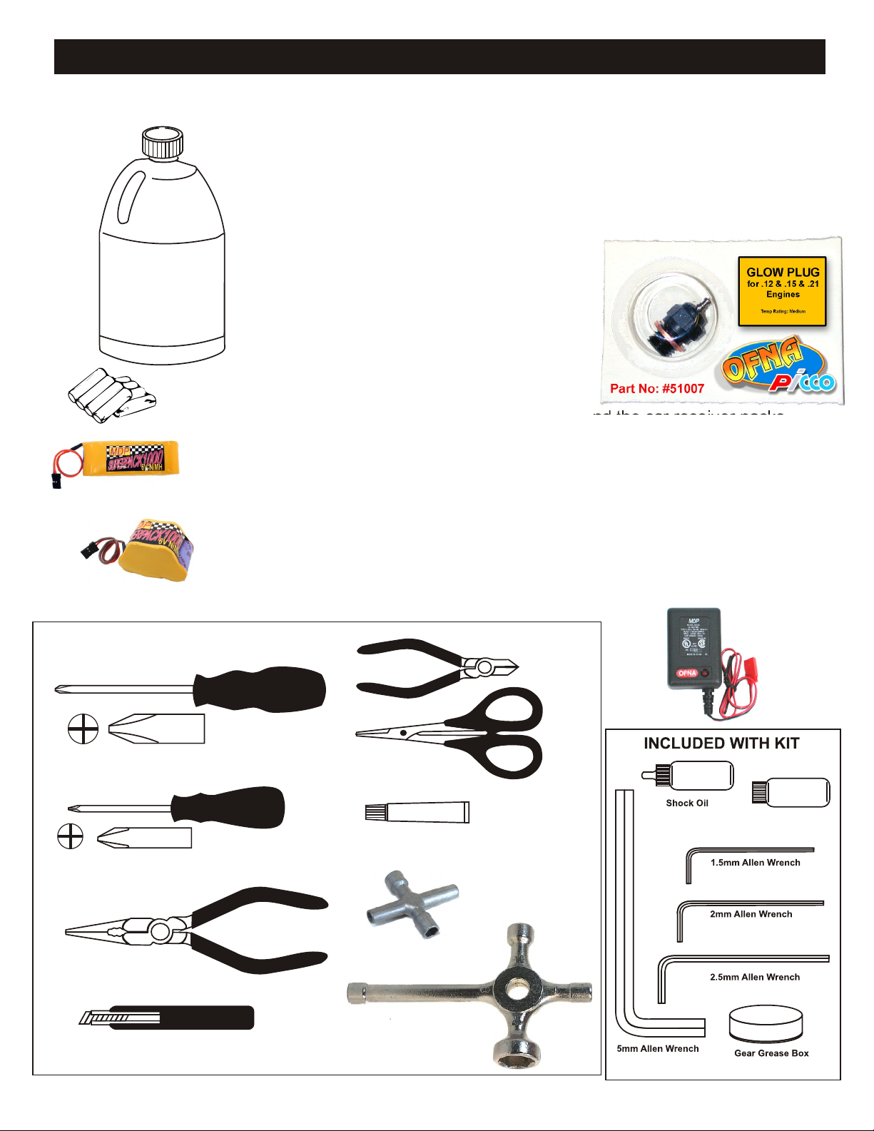
REQUIRED FOR OPERATION
THINGS NEEDED
Glow Fuel
20%
AA Batteries ( 12 pcs )
#10211 NiHm Flat Pack,
see charger 10214.
You will need to buy a few items to start the engine and run the car.
• Use 20% nitro CAR fuel. Do not use airplane or heli fuels, they will
over heat engine.
• Rear Exhaust .12 engine with SG crankshaft and Slide Carb.
• Buy SHORT glow plugs, OFNA/PICCO Plug (#51007) are long
therefore use two copper washers. Use plugs without idle bar. Always
use two copper washers with Picco glow plugs.
I
You need to get batteries for the radio transmitter and the car receiver packs.
• Radio TX needs (8) eight AA batteries.
• Car needs (4) four AA Ni-cad batteries, Alkaline type batteries will work, but
braking will be reduced. The best is to use a 5 cell hump pack for increased
voltage..
Recommended Option:
You may want to upgrade the car battery pack to a Ni-Cad or NiHm 5 cell
#10212 NiHm Hump Pack,
see charger 10214.
TOOLS NOT INCLUDED IN KIT,
BUT NEEDED TO MAINTAIN YOUR CAR.
Phillips Type Screw Drivers ( L )
Phillips Type Screw Drivers ( S )
Needle Nose Pliers
type(600AE). This will give more run time. OFNA # 10211 or 10212 1000NiMh
Hump Pack and NiHm Battery Charger #10214
Cutter
Curved Scissors
Instant Cement
Cross Wrench
#17109 $3.95
10214
Over-nite
Charger
Diff Oil Silicone
Knife
Glow Plug & 17MM Cross Wrench
#10801 $6.95
Page 3

MUST READ THIS BEFORE RUNNING
Running a nitro kit is fun and easy, but to make this a safe Precautions
and good experience you must observe a few rules. This
kit is extremely fast, easily over 40MPH, and can seriously
injure someone if you are not careful.
Where to run car?
• Any running area you choose must be dry. Do not run
car near any water or wet dirt.
• Do not run on public streets. It is very easy to have the
car run over or damaged by hitting the curb.
• Do not operate car in tight confined places. The car is
very fast and will easily hit something.
• Do not run near people or animals.
and will too easily hit someone.
• Due noise, you will want to consider the surrounding car or property.
area when operating the car.
• Do not operate the car at night. You will not be able to
drive it without hitting something.
• Do not operate the car indoors. Engine exhaust is not flammable and poisonous.
healthy.
Glow Fuel label for additional precautions.
• Glow fuel is poisonous!
• Glow fuel is flammable! • Car Fuel tank - Never store fuel in car tank, it will ruin the
• Do not leave in fuel bottle with lid off at any time.
• Do not use any fuel other than glow fuel in this engine.
First Time Starting the Engine
Caution! When starting engine make sure the following is
observed.
• Set engine Master needle to 3 turns (rich setting)
• Do not do this alone, get an experienced friend to help at
first.
• Fill fuel tank, try not to spill fuel. Do not spill fuel on
receiver
• Hold car off the ground, so it will not runaway when first
starts
• Turn on Radio and check the linkage before starting
engine.
• Turn on car receiver battery switch.
• Always have an air filter on the carburetor to keep dirt
out.
The car is very fast
• This kit is not a toy. Always run car with a second
person as a spotter and pitman.
• Hot Parts - The pipe, manifold, engine and head are very
hot and will cause burns.
• Rotating Parts - Keep hands away from the drive train,
wheels, and engine when engine is running.
• Radio - Check batteries life before running the car. If
radio does not have full control of the car with steering
and/or throttle/brake do not run until corrected. Failure to
correct this will result in possible injury and damage to the
• Glow fuel - Do leave the glow fuel unattended with the lid
off. Fuel contains Methanol and Nitro Methane and is
Store fuel in cool ventilated location. Refer the glow fuel
engine if left in tank.
• Always turn off the car BEFORE turning off radio.
• DAMAGE DUE CAR RUN AWAY IS NOT A WARRANTY
ISSUE.
IF YOU DO NOT BREAK-IN ENGINE
CORRECTLY, MAINLY AT LOW RPM,
YOU WILL BREAK THE CONNECTING
ROD!
FAILURE TO NOT READ AND
FOLLOW BREAK-IN ENGINE
Emergency Stopping Engine When Running
• Remove air filter and cover carb. intake.
• Squeeze fuel line and hold until engine stops.
• With a rag, cover exhaust outlet.
Storing Car After Running
• Remove fuel from tank and fuel lines
• Turn off radio in car
• Put a few drops of after run in engine to keep it from
rusting.
• Clean oil and dirt from chassis with a degreaser.
INSTRUCTIONS WILL VOID
WARRANTY!
CHECK RADIO SETTING AND
LINKAGE BEFORE STARTING
Page 4

THE NEXT 3 PAGES ARE THE ADDENDUM
INSTRUCTION FOR THE LD-3 PRO KIT
Page 5
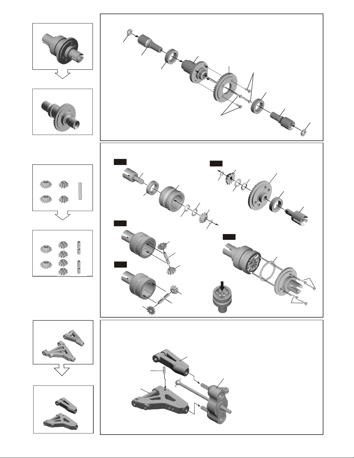
Front Diff
Parts Upgrade
38410 - Front One-Way
PRO FRONT ONE WAY ASSEMBLY
37967
O-Ring
38413
CAP JOINT
37450
10x15x4mm
Ball Bearing
38411
One Way
38412
Large
Bevel Gear
(steel)
94052
M2x6mm
Flat Head
Screw
37450
10x15x4mm
Ball Bearing
38413
CAP JOINT
Standard 4 Diff. Gear
13T
13T
Parts Upgrade
38403 - 6 Gears Diff. Set
Must 12T gear with 6 gear setup.
12T
12T
94052
M2x6mm
Flat Head
Screw
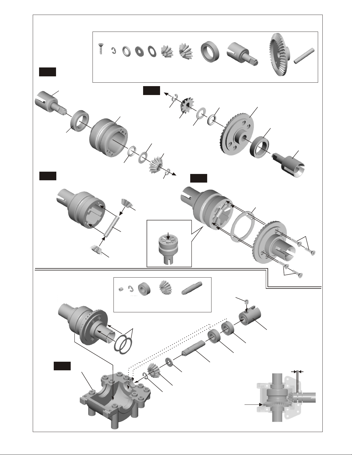
PRO ASSEMBLY OF THE REAR DIFFERENTIAL
Step 1
Step 3
Step 4
Step 1
38255
Cap Joint
37450
10x15mm
Bearing
38252
Diff.Case
38278
5x8x1.5mm
O-Ring
38256
10T Diff.Gear
(small)
38404
3x17.8mm
Cross Pin
38256
10T Diff.Gear
(small)
Step 2
94045
2mm
E-Ring
38278
5x10mm
Washer
38402
12T Diff.Gear
(Large)
94045
2mm
E-Ring
Put the grease into the diff.
case before assembly.
38278
5x10mm
Washer
Step 5
38402
12T Diff.Gear
(Large)
38278
5x8x1.5mm
O-Ring
38416
Large Bevel Gear
(Steel)
37450
10x15mm
Bearing
38287
Diff.Gasket
37967
O-Ring
38255
Cap Joint
94051
M2x6mm
Flat Head
Tapping Screw
39053 Upper & Lower Arms
Parts Upgrade
38399 Upper & Lower Arms (F&R)
38256
10TDiff.Gear
38256
10T Diff.Gear
(small)
38404
3x17.8mm
Cross Pin
(small)
PRO ASSEMBLY OF THE FRONT SUSPENSION
*For the Front knuckle assembly,
please use page 6 of 1.
Front knuckle
arm Assembly
94035
3x8 mm
Set Screw
38399
Front Lower Arm
38399
Front Upper Arm
M2x6mm
Flat Head
Tapping Screw
Page 6
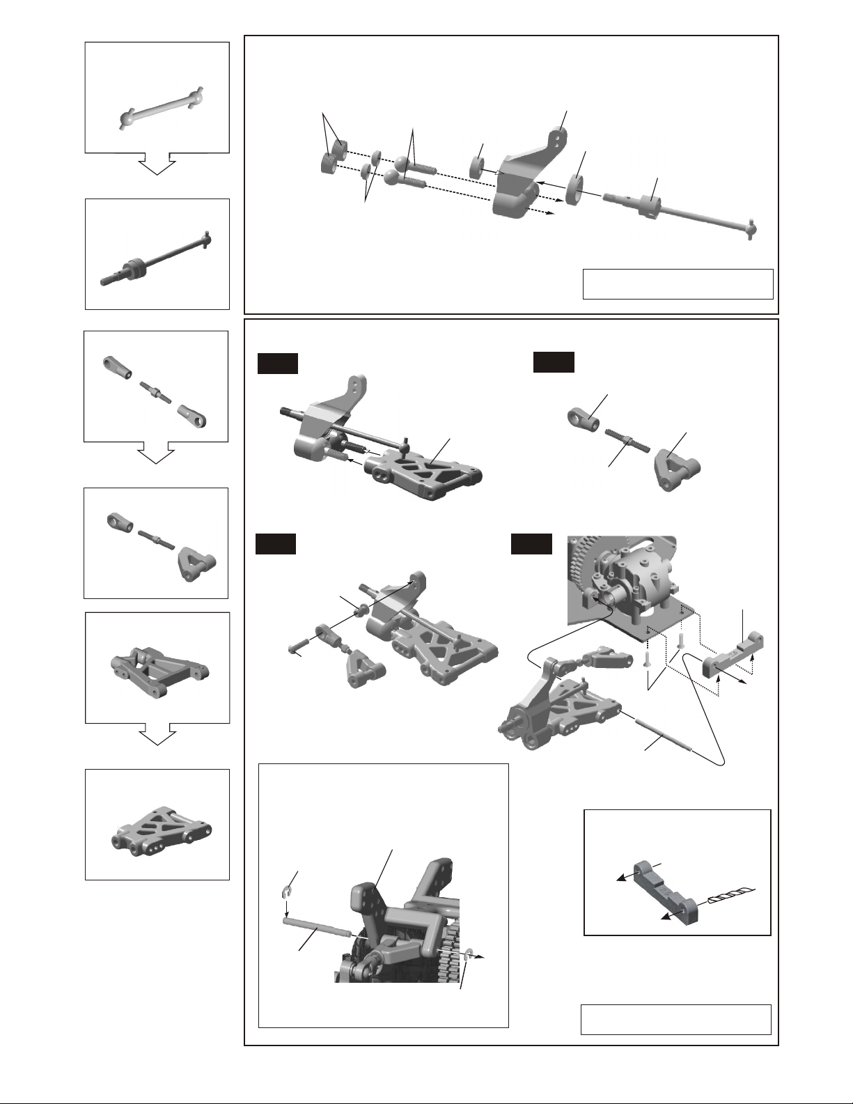
38268 - Rear Drive Shaft
PRO ASSEMBLY OF THE REAR HUB
Parts Upgrade
CVA Joint
38405
Rear Upper Arms
Parts Upgrade
38399 - Rear Upper Arms
39150
10mm Alum.
Set Screw
39140
8mm
Steering Ball
38266
8mm
Steering Ball
Washer
*Notice the direction
of the steering ball washer.
37430
5x11x4mm
Ball Bearing
38266
Rear Wheel
Hub
PRO ASSEMBLY OF THE REAR SUSPENSION ARMS
Step 1
38399
Rear Lower Arm
Step 2
37450
10x15x4mm
Ball Bearing
38405
CVA Joint
Assembly of the right and left-side are the same.
38399 Rear Upper Arm
Ball End
38399 Rear Upper Arm
Ball End
38398
3x20mm
Turnbuckle
Rear Lower Arms
Parts Upgrade
38399 - Rear Lower Arms
Step 3Step 3
37370
6mm
Ball&Socket
94004
M3x12mm
Screw
Insert the upper arm shaft after assembly the shock tower.
38270
90020
2.5mm
E-Ring
Shock Tower
Step 4
94019
M3x10mm
Flat Head
Hex Screw
38419
Lower Arm Shaft
For assembly front roll bar:
* Use a 3mm drill to drill
a hole in the arm holder
before assembly.
* Use the 0 degree
for rear arm holder.
38263
Arm Holder
(Rear / Rear)
38261
Rear Upper shaft
90020
2.5mm
E-Ring
Assembly of the right and left-side are the same.
Page 7
38417 - Blade Swaybar Set
38319 - CHASSIS 2.5mm
Parts Upgrade
38489 - CHASSIS 3.0 mm Ld3 Pro
3 Shoes Flywheel 34mm, Pull Start
38284 -
Parts Upgrade
PRO ASSEMBLY OF THE STABILIZER INTO ARM BLOCK
* Assembly the rear anti-roll bar same as the front.
94033
Step3
M3x3mm
Set Screw
38419
3x55mm
Lower Arm
Shaft
Step1
M3x15mm
Screw
38418rs
Mount
38418
Stabilizers
Balance
Adjuster
94033
M3x3mm
Set Screw
* Keep stabilizer ball in the center.
94033
M3x3mm
Set Screw
Step2
38418
Stabilizers
Mount
94005
M3x15mm
Screw
38420
Stabilizers
blades
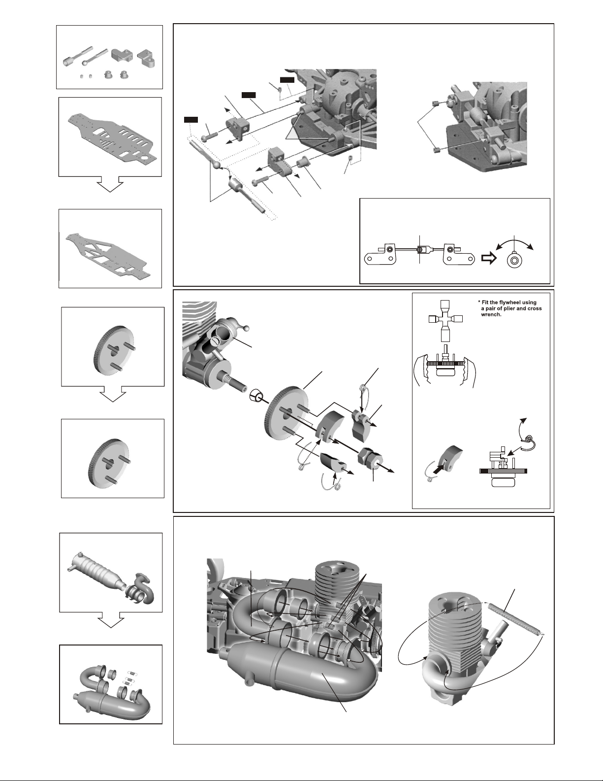
ASSEMBLY OF THE FLYWHEEL
SG Type Engine
10330
Split Cone
38285
3 Shoes Flywheel
(Small/30mm)
10100
Clutch Spring
10010
Clutch Shoes
Center
* Turn stabilizer balance adjuster to
adjust the stabilizer to the same angle.
* Place the clutch shoes
with the clutch springs
over the 3 pins of the
flywheel.
Using a small screw driver
or needle nose pliers and push
the small end of the clutch
spring behind the pilot shaft
nut and down.
If installed correctly, the shoes
will be held in with spring
tension.
- 3 Shoes Flywheel, non-pull Start
38285
(Small/30mm)
10063 - polished 6 Ring Pipe
38286 - Side Exht Manifold
Parts Upgrade
38475 - Polished
IN-LINE REAR EXHAUST PIPE
Pull Start Engine Mounts
#38150
Non-Pull Start Engine Mounts
#38453
10098
SG
Clutch Nut
PRO ASSEMBLY OF THE MANIFOLD AND MUFFLER
38477 - Manifold
In-Line Rear Exhaust Manifold
Polished
97501
Manifold Spring
* Put the clutch spring into the groove
of the clutch shoesbefore assembly.
10121
Manifold Spring
38476 - Pipe
In-Line Rear Exhaust Manifold
Polished
Page 8

FOLLOWING PAGES INCLUDE ASSEMBLY
FOR LD-3 RTR AND LD-3 PRO
Page 9
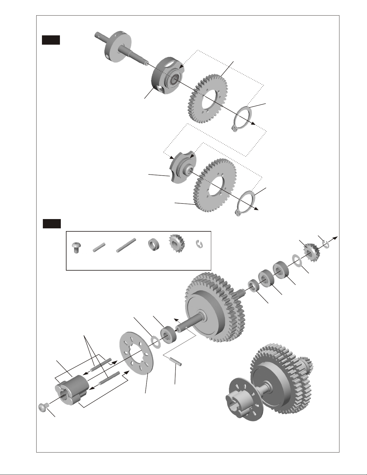
ASSEMBLY OF THE 4 GEAR DIFFERENTIAL
(Build two differentials for front and rear.)
Step 1
Step 3
38255
Cap Joint
37450
10x15x4mm
Ball Bearing
94051
M2x6mm
Flat Head
Tapping
Screw
2mm
E-Ring
O-Ring
5x8x1.5mm
38252
Diff.Case
38278
5x8x1.5mm
O
38278
38253
3x17.8mm
Pin
5x8x0.8mm
5x10mm
Washer
Washer
Step 2
5x10mm
Washer
38256
10T Diff.Gear
(small)
Put the grease into the diff. case
before assembly.
38256
10T Diff. Gear
(small)
2mm
E-Ring
37771
13T
Diff. Gear
2mm
E-Ring
37771
13T
Diff. Gear
(Large)
37771
13T Diff. Gear
(Large))
(Large)
5x10mm
Washer
Step 4
37450
10x15x4mm
Bearing
O--RRiinngg
38278
5x8x1.5mm
38255
Cap Joint
38257
Large
Bevel Gear
38257
Large
Bevel Gear
37450
10x15x4mm
Ball Bearing
38287
Diff.Gasket
Note: Peel off backing
38253
3x17.8mm
Pin
38255
Cap Joint
M2x6mm
Flat Head
Tapping Screw
38256
10T Diff.Gear
(small)
ASSEMBLY OF THE FRONT GEAR BOX
(Build a gear box for front.)
NOTE: DIFF GEARS AND PINION WILL
FEEL ROUGH UNTIL YOU RUN CAR. DO
NOT SHIM GEAR CASE FOR
SMOOTHNESS OTHERWISE GEAR WILL
STRIP.
38251
Step 1
Gear case
3x3mm
Set Screw
94033
90020
2.5mm
E-Ring
38254
12x15x0.25mm
Shim
38258
37430
16T
5x11x4mm
Ball Bearing
*Adjust the backlash
Bevel Gear
(small)
*Use 2 pcs in this side.
with the shim*
E-Ring
16T
90020
2.5mm
38259
16T
5x8x0.8mm
Washer (important)
38258
Bevel Gear
(small)
Bevel Gear
(small)
Shaft
16T
38259
3x3mm
Set Screw
Bevel Gear
(small)
Shaft
* Put the gear in the
right position.
37430
5x11x4mm
Ball Bearing
37430
5x11x4mm
Ball Bearing
M2x6mm
Flat Head
Tapping Screw
38260
Bevel Gear
16T
Cap Joint
*Check the right space
between two ball bearings.
Page 10
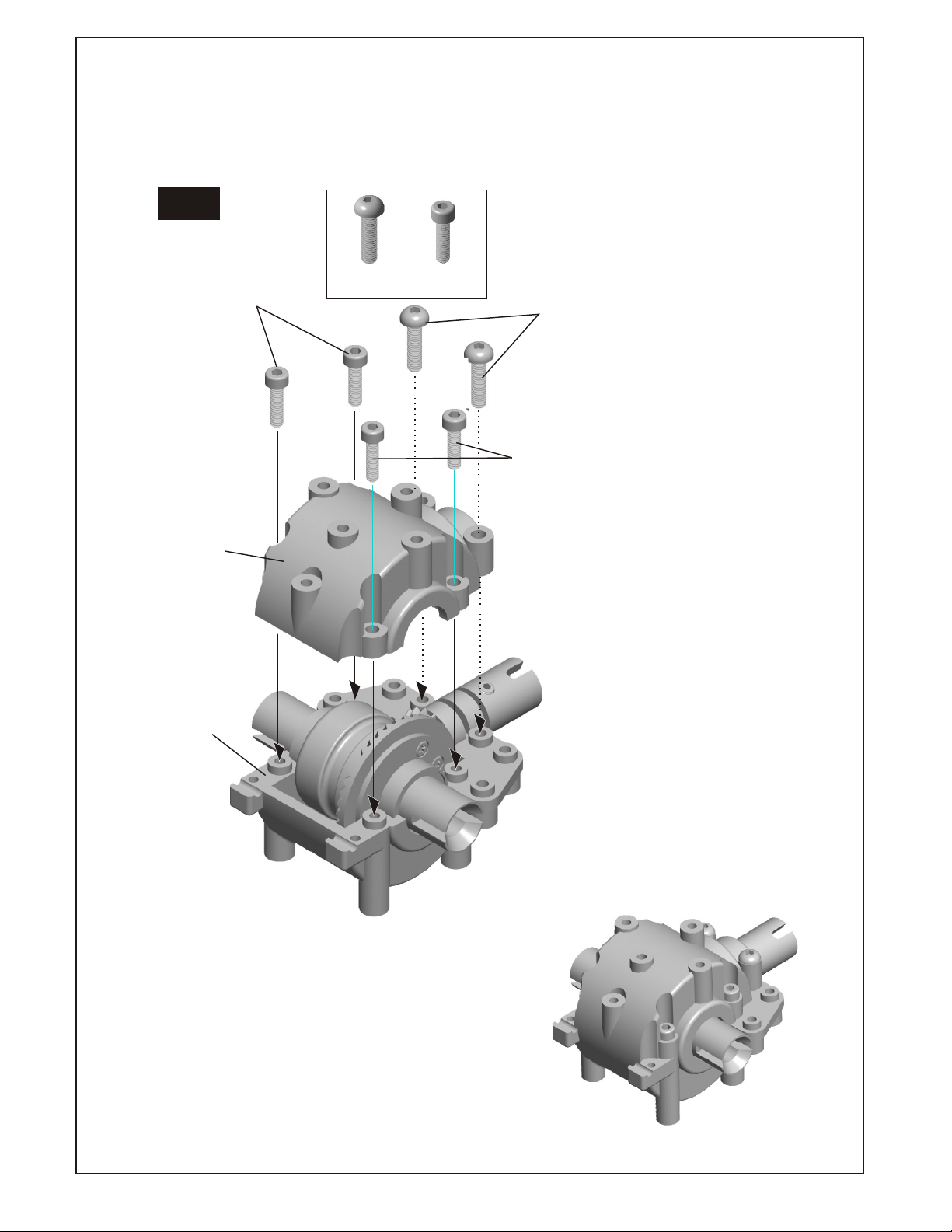
ASSEMBLY OF THE FRONT GEAR BOX
(Build a gear box for front.)
Step 2
* The gear box after assembly.
38251
Gear Case
38251
Gear Case
M2.6X10mm
Screw
94050
M3X12mm
Screw
94004
M2.6X10mm
Screw
94050
M2.6X10mm
Screw
94050
38321
M3X12mm
Screw
94004
Page 11
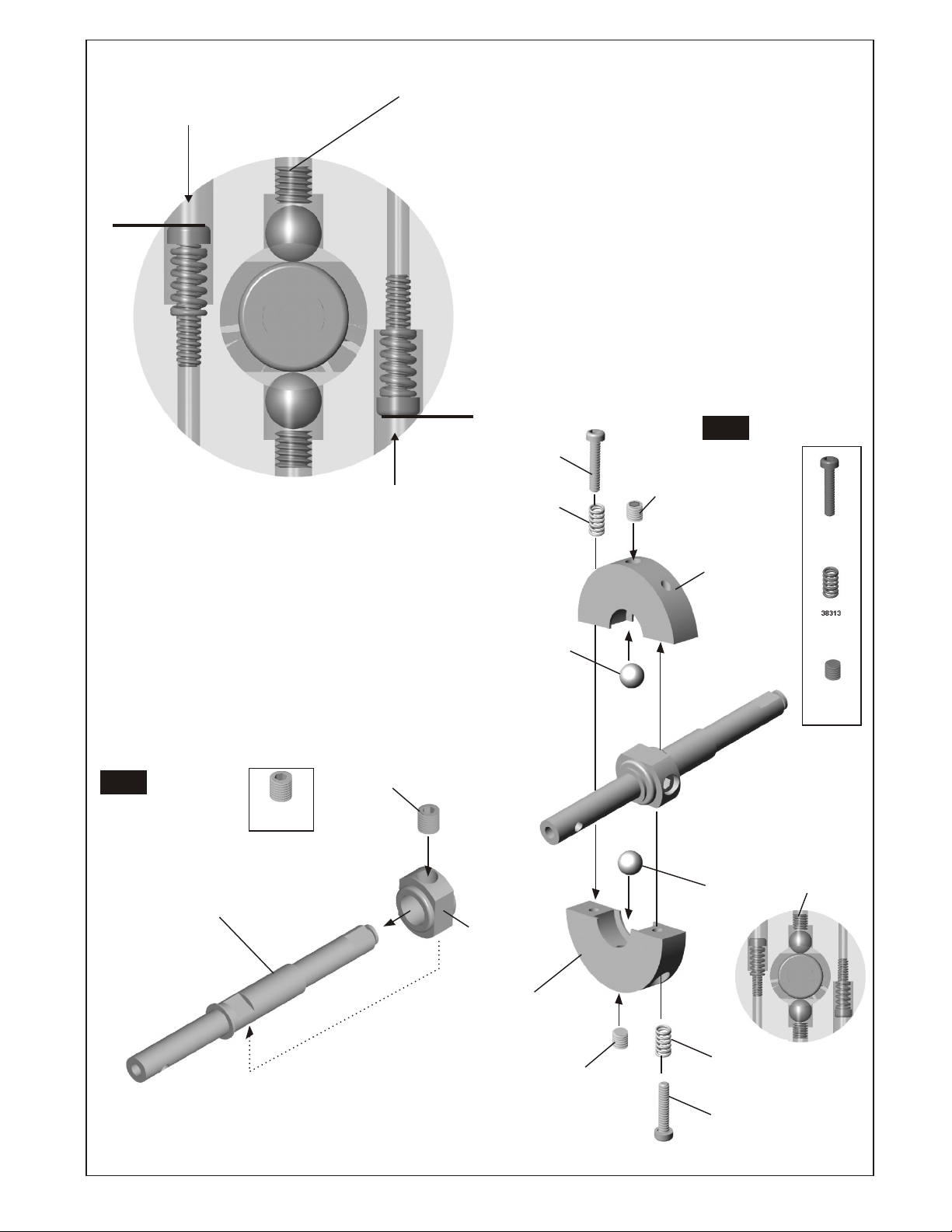
ASSEMBLY OF 2-SPEED CLUTCH TRIGGER DISC
SCREW AS SHOWN,
LEVEL WITH HOLE EDGE
SCREW AS SHOWN,
LEVEL WITH HOLE EDGE
SET BALL TO REST ON CAM, NOT PUSHING. IF
TOO TIGHT, THE BALL WILL PUSH ON CAM
SPREADING SHOE DISC AND WILL NOT FIT
INTO ALUM. CLUTCH BELL #38296
CARE MUST BE TAKEN TO BUILD
THIS ASSEMBLY CORRECTLY,
OTHERWISE 2-SPEED WILL NOT
ADJUST AND MAY NOT WORK AT ALL.
IN FACT, IF 2-SPEED DOES NOT
SHIFT, CHECK OUT THIS ASSEMBLY!.
Step 2
M2x10mm
Screw
3x3mm
38313
Spring
Set Screw
38312
Clutch Shoe
M2x10mm
Screw
ASSEMBLY OF THE TWO SPEED GEAR
Step 1
4x4mm
Set Screw
38323
2 Speed Main Shaft
94034
4x4mm
Set Screw
Note: Must use Locktite
38316
Clutch Shoe
Carrier
38312
Clutch Shoe
38315
Metal Ball
94033
3x3mm
Set Screw
38315
Metal Ball
38313
Spring
94033
3x3mm
Set Screw
38313
Spring
3x3mm
Set Screw
M2x10mm
Screw
Page 12
ASSEMBLY OF THE TWO SPEED GEAR
Step 3
38300
38T
Spur Gear
38T
Step 4
M3x4mm
screw
37400
2x8.8mm
Pin
38295
1 st Gear Carrier
38279
3x14.8mm
Pin
38296
2nd Gear
Clutch Bell
(Ball Bearing)
(One-Way)
37430
5x11x4mm
Ball Bearing
38301
42T
Spur Gear
42T
38258
16T
Bevel Gear
(Small)
90020
2.5mm
E-Ring
38297
Retaining Ring
38297
Retaining Ring
38258
16T
Bevel Gear
(Small)
90020
2.5mm
E-Ring
*Insert the 382790 into
Break disc mount.
38279
3x14.8mm
Pin
38289
Brake Disc
Mount
38321
M3x4mm
screw
Note: Must use Locktite
37430
5x8mm
Washer
5x11x4mm
Ball Bearing
40042
Brake Disk
*Put the brake disk on
before assembly
37400
2x8.8mm
Pin
38289
5x8mm
Plastic
37430
5x11x4mm
Ball Bearing
5x8x0.8mm
Washer
37430
5x11x4mm
Ball Bearing
Page 13

ASSEMBLY OF THE BRAKE AND DIFF.MOUNT
*Take off the double sided tape
before assembly.
1
94004
M3x12mm
Screw
94049
M2.6x8mm
Screw
ASSEMBLY OF THE BRAKE AND 2-SPEED
40044
Spring
M3x12mm
Screw
2
38271
Brake Pad
1
38272
Brake Pad
Linings
2
M2.6x8mm
Screw
38272
Brake Pad
Linings
38271
Brake Pad
40044
Blake Pad
Spring
38289
Bulk Head
cover
38289
Plastic Bushing
38273
Brake Cam
38289
Brake Mount/Upper
Note: Cam will fit in one
direction. Check step.2
on page 9. Note plastic
stop tab on backside.
94005
M3x16mm
Screw
94005
M3x16mm
Screw
38289
Brake Mount/Lower
Page 14

ASSEMBLY OF THE REAL GEAR BOX
(Build a gear box for real)
*Adjust the backlash
with the shim.
*Use 2 pcs in this side.
Step 1
Step 2
DIFFERENTIAL
38254
12x15x0.25mm
Shim
94050
M2.6x10mm
Screw
ASSEMBLY
* Add Gear Grease before
closing gear case.
94004
M 3x12mm
Screw
38254
12x15x0.25mm
Shim
37430
5x11x4mm
Ball Bearing
38251
Gear box
94050
M2.6x10mm
Screw
38251
Gear box
94004
M 3x12mm
Screw
Screw
Note: Do not over tighten screws
94050
M2.6x10mm
Screw
Page 15

ASSEMBLY OF THE FRONT KNUCKLE ARMS AND CVA SHAFT
Assembly of the right and left-side are the same.
*Make steering
ball move smooth.
39150
10mm
Hex Screw
39190
CVA
Constant Velocity
Axle
37450
10x15x4mm
Ball Bearing
37430
5x11x4mm
Ball Bearing
Step 2
*"L" make are for
left-side.
37450
10x15x4mm
Ball Bearing
38265
Front Knuckle Arm
(Left)
37430
5x11x4mm
Ball Bearing
39140
8mm
Steering Ball
39141
8mm
Steering Ball
Washer
ASSEMBLY OF THE FRONT SUSPENSION ARMS
39140
8mm
Steering Ball
39150
10mm
Hex Screw
*Notice the
direction hex screw.
Step 1
*Push 2 ball bearings into
knuckle arm as shown.
38265
Front Knuckle Arm
(Right)
Assembly of the right and left-side are the same.
94035
3x8 mm
Set Screw
94035
3x8 mm
Set Screw
39060
Front Lower Arm
39053
Front Upper Arm
FRONT KNUCKLE
ARM ASSEMBLY.
FRONT KNUCKLE
ARM ASSEMBLY.
39060
Front Lower Arm
39053
Front Upper Arm
Page 16

ASSEMBLY OF THE REAR WHEEL HUB
Assembly of the right and left-side are the same.
39150
10mm
Hex Screw
*Notice the direction
of the steering ball washer.
Step 1
37430
5x11x4mm
Ball Bearing
39150
10mm
Hex Screw
37450
10x15x4mm
Ball Bearing
39140
8mm
Steering Ball
ASSEMBLY OF THE REAR SUSPENSION ARMS
94004
M3x12 mm
Screw
37370
6 mm
Ball and Socket
94035
3x8 mm
Set Screw
(Right Side)
* Take the upper arm plastic
rod end from shock plastic tree.
37370
6 mm
37100
Upper Arm
Plastic Rod End
Ball & Socket
39141
8mm
Steering Ball
Washer
94035
3x8 mm
Set Screw
39140
8mm
Steering Ball
REAR UPPER ARM
Approx 46 mm
37430
5x11x4mm
Ball Bearing
(Left Side)
38266
Rear Wheel
Hub
Step 2
Assembly of the right and left-side are the same.
* Take the upper arm plastic
rod end from shock plastic tree.
37370
6 mm
Ball & Socket
Push
*Push 2 ball bearing into
rear wheel hub as shown.
37450
10x15x4mm
Ball Bearing
37100
Upper Arm
Plastic Rod End
M3x12 mm
Screw
Push
38267
Rear Wheel
Axle Shaft
37210
3x15mm
Turnbuckle
94004
M3x12 mm
Screw
Right
37210
3x15mm
Turnbuckle
37100
Upper Arm
Plastic Rod End
Left
3x8 mm
Set Screw
37100
Upper Arm
Plastic Rod End
Page 17

ASSEMBLY OF THE SEVRO SAVER
Step 1
94041
M3
Nylon Nut
37360
4mm
Ball & Socket
94003
M3x10mm
Screw
94004
M3x12mm
Screw
38288
Servo Saver
Spring
36742
Servo Saver
Bushing
38276
3x6 mm
Brass Bushing
38277
5x8 mm
Brass Bushing
38276
3x6x2.4 mm
Brass Bushing
37360
4mm
Ball & Socket
36742
Servo Saver
Bushing
94004
M3x12mm
Screw
38289
Servo Saver
94004
M3x12mm
Screw
38276
3x6x2.5 mm
Brass Bushing
94041
M3
Nylon Nut
38289
Servo Saver
94004
M3x12mm
Screw
37360
4mm
Ball & Socket
38288
Servo Saver
Spring
36742
Servo Saver
Bushing
37360
4mm
Ball & Socket
* Use the long ball end for both
Step 2
*Made two steering rod
for left and right hand side.
steering rod and steering servo rod.
37650
4mm
Ball End
A
38281
3x40mm
Turnbuckle
A
Steering Rod
Approx 57 mm
Steering Servo Rod
B
37650
4mm
Ball End
37650
4mm
Ball End
38280
3x36mm
Turnbuckle
37650
4mm
Ball End
38277
5x8x2.5 mm
Brass Bushing
Step 3
A
38289
Servo Saver
* Snap on steering rod to
4mm ball & socket.
38277
5x8x2.5 mm
Brass Bushing
38289
Servo Saver
* Snap on steering rod to
4mm ball & socket.
A
* Snap on steering rod to
4mm ball & socket.
B
B
Approx 54 mm
The servo saver after assembly.
Page 18

ASSEMBLY OF THE SEVRO SAVER
ANDSTEERING RODS
38275
Servo saver
Screw
94041
M3
Nylon Nut
94018
M3x5mm
Flat Head
HexScrew
94041
M3
Nylon Nut
38319
Chassis, Stock RTR
Note: Use Lock-tite
94018
M3x5mm
Flat Head
Hex Screw
38275
Servo saver
Screw
M3x10mm
Flat Head
Hex Screw
94019
Front Gear Box Assembly.
M3x10mm
Flat Head
Hex Screw
94019
38263
Arm Holder
(Lower/Rear)
M3x10mm
Flat Head
Hex Screw
0 Degree
ASSEMBLY OF THE FRONT BLOCK ONTO CHASSIS
38262
50mm
Lower Arm Shaft
*Insert the drive shaft before assembly.
38263
Arm Holder
(Front/Lower)
0 Degree
M3x10mm
Flat Head
Hex Screw
M3x10mm
Flat Screw
94019
M3x10mm
Flat Head
Hex Screw
37360
4mm
Ball & Socket
38262
50mm
Lower Arm Shaft
37360
4mm
Ball & Socket
Assembly of the right and left-side are the same.
38263
Lower Arm Holder for 0 and 1.5 and 2.5 degree.
Page 19

ASSEMBLY OF THE ARM
HOLDER ONTO CHASSIS
M3x10mm
Flat Screw
38263
Arm holder
(Rear/Front)
94019
M3x10mm
Flat Head
Hex Screw
1.5 Degree
ASSEMBLY OF THE TWO SPEED
AND REAR GEAR BOX ONTO CHASSIS
* Insert the center drive shaft
before assembly the rear gear onto
chassis.
38264
Center Drive Shaft
94024
M3x30mm
Flat Head
Hex Screw
94024
M3x30mm
Flat Screw
94019
M3x10mm
Flat Screw
94019
M3x10mm
Flat Head
Hex Screw
ASSEMBLY OF THE REAR ARM HOLDER
38262
94019
M3x10mm
Flat Screw
50mm
Lower Arm Shaft
94019
M3x10mm
Flat Head
Hex Screw
38262
51mm
Lower Arm Shaft
94019
M3x10mm
Flat Head
Hex Screw
38263
Arm Holder
(Rear / Rear)
0 Degree
Assembly of the right and left-side are the same.
Page 20

ASSEMBLY OF THE STEERING SERVO AND
THROTTLE SERVO
ASSEMBLY OF THE RADIO TRAY
Step 1
Step 2
38290
Radio Tray
M3X8mm
Hex Screw
94003
M3X10mm
Hex Screw
10769
Servo
Horn Adapter
94003
M3X10mm
Hex Screw
38289
Servo Adapter
38289
Servo Post
94003
M3X10mm
Hex Screw
Screw
THROTTLE
SERVO
*Use the screw provided
from your servo.
10768
Steering
Servo Horn
37360
4mm
Ball & Socket
94003
M3X10mm
Hex Screw
38289
Servo Post
38289
Servo Adapter
Step 1
Step 2
94047
M2X 6mm
Hex Screw
Receiver
37410
Body Clip
38292
Receiver Box
You can use flat or hump or
4 cell RTR battery packs in
battery box
94047
M2X 6mm
Hex Screw
Battery
37410
Body Clip
38317
Battery Cover
38318
¹q¦À²°»\
Lid, Battery Cover
with Failsafe unit
¹q¦À²°»\
94003
M3X10mm
Hex Screw
94003
M3X10mm
Hex Screw
Steering Servo
A
M3X8mm
Hex Screw
38290
Sevro Post
A
Switch
Align the servo horn in 90 degree.
*Use the screw provided
Screw
from your servo.
Degree
90
10280
Switch
94047
M2X 6mm
Hex Screw
Page 21

ASSEMBLY OF THE RADIO TRAY ONTO CHASSIS
The picture show of the radio assembly
from left-side .
94019
M3x10mm
Flat Head
Screw
94002
M3x8mm
Screw
94002
M3x8mm
Screw
B
94019
M3x10mm
Flat Head
Screw
94002
M3x8mm
Screw
94019
M3x10mm
Flat Head
Screw
94002
M3x8mm
Screw
C
A
ASSEMBLY OF THE STIFFENER
94019
M3x10mm
Flat Head
Screw
38290
Front Stiffener
94019
M3x10mm
Flat Head
Screw
94002
M3x8mm
Screw
94002
M3x8mm
Screw
Front Gear Box
94002
M3x8mm
Screw
Rear Gear Box
38290
Rear Stiffener
94019
M3x10mm
Flat Head
Screw
Page 22

ASSEMBLY OF THE FRONT SHOCK TOWER
AND FRONT UPPER ARM
94002
M3x8mm
Screw
94004
M3x12mm
Screw
90020
2.5mm
E-Ring
Insert the front caster into front upper arm.
39141
Caster Angle
Adjuster(1.5mm)
ASSEMBLY OF THE REAR SHOCK TOWER
ONTO REAR GEAR BOX
94004
94002
M3x12mm
M3x8mm
Screw
Screw
94004
M3x12mm
Screw
94004
90020
2.5mm
E-Ring
38261
Front Upper
Arm Shaft
M3x12mm
Screw
94002
M3x8mm
Screw
38270
Shock Tower
Assembly of the right and left-side are the same.
ASSEMBLY OF THE REAR DRIVE SHAFT
90020
2.5mm
E-Ring
38270
Shock Tower
Assembly of the right and left-side are the same.
ASSEMBLY OF THE FUEL TANK
ONTO CHASSIS
38335
Fuel Nipple
94002
M3x8mm
Screw
37370
6mm
Ball & Socket
94006
M3x18mm
Screw
37370
6mm
Ball & Socket
94041
M3
Nylon Nut
*Insert the rear drive shaft
before assembly.
94006
M3x18mm
Screw
Assembly of the right and left-side are the same.
38268
Rear Drive
Shaft
94019
M3x10mm
Flat Head
Hex Screw
Step 2
94019
M3x10mm
Flat Head
Hex Screw
Step 1
3x3mm
Set Screw
38293
Fuel Tank
Page 23

ASSEMBLY OF THE ENGINE
94041
M3
Nylon Nut
3X8 mm
Washer
35958
5x8x2.5mm
Ball Bearing
5x10x4mm
Ball Bearing
38313
7mm
tapered cone
10098
SG
Clutch Nut
SG Crank Shaft
38285
When installing an engines with a SG cranks shaft, you must use the
#180D clutch nut and 7mm tapered cone.
Flywheel, SG
M3x5mm
Screw
M3x12mm
Screw
59020
Pilot Shaft
* Place the clutch shoes
with the clutch springs
over the 3 pins of the
flywheel.
Using a phillips screw driver
or needle nose pliers and bend
the small end of the clutch
spring behind the pilot shaft
#176D or #180D than press
down.
ASSEMBLY OF THE 2-SPEED CLUTCH BELL
38284
Threaded
3 Shose Flywheel
* Put the clutch spring into the groove
of the clutch shoesbefore assembly.
10100
Clutch Spring
10010
Clutch Shoes
59020
Threaded
Pilot Shaft
Note: For Single Speed Assembly, see
back APPENDIX pages!
34110
5x10x4mm
Ball Bearing
35951
Clutch Bell
35945
20T-2nd
Clutch Gear
35944
16T-1st
Clutch Gear
*Put the 35958 before assembly
the clutch gear.
35958
5x8mm
Ball Bearing
3X8 mm
Washer
M3x5mm
Screw
Page 24

ASSEMBLY OF THE ENGINE
ONTO ENGINE MOUNT
38150
M3x12mm
Hex Screw
38150
M3
Nylon Nut
38150
M3x12mm
Hex Screw
ASSEMBLY OF THE MANIFOLD
94007
M3x20mm
Cap Screw
38162
Manifold Gasket
94007
M3x20mm
Cap Screw
38150
Engine Mount
*Put the nylon nut
into the groove of the
engine mount.
38150
M3
Nylon Nut
ASSEMBLY OF THE ENGINE ONTO CHASSIS
94003
M3x10mm
Screw
38286
Side Exhaust
Manifold
Note book Paper.
* Use the note book paper to set gear backlash
between Spur Gear and Clutch Bell Gear.
* If the space is not correct, the spur gear will
be damaged.
2 Speed
Spur Gear
90 Degree
2 Speed Bell
94003
M3x10mm
Screw
M3x10mm
Screw
* Loose or tighten 3x12mm cap screw
to align spur gear and clutch bell gear
to 90 degree.
Page 25

ASSEMBLY OF THE BRAKE LINKAGE
( For slide carburetor. )
3x3mm
3x3mm
Set Screw
Set Screw
Step 1
30530
Throttle
Ball End
Step 3
M2x12mm
Screw
3x3mm
Set Screw
Step 2
10300
Alum.
Stopper
Throttle
Spring
36130
Throttle
Slider
38180
Throttle
Rod
3x3mm
Set Screw
30171
2mm
Rod
10300
Alum.
Stopper
10300Alum.
Stopper
* Take the 2mm plastic washer from
the shocks plastic tree.
ASSEMBLY OF THROTTLE HORN INTO SERVO AND BRAKE LEVER
2mm
Plastics Washer
10768
Servo Horn
10769
Sevro Horn
Adapter
94033
3x3mm
Set Screw
*Use the screw provided from your servo.
Screw
38274
Brake Lever
THROTTLE
SERVO
* Align the throttle servo horn in 90 degree.
* Attach the throttle ball end onto
the throttle ball on the carburetor
Page 26

ASSEMBLY OF THE MUFFLER
Step 1
10063
Muffler
90012
Pressure
Nipple
38320
Silicone Tube
Nylon Strap
8 inch
Step 2
94034
4x4mm
Set Screw
38327
Muffler Stay
3x8mm
Washer
94003
M3x10mm
Screw
INSTALLATION OF AIR FILTER
* Insert the filter into air filter holder.
Apply filter oil to the sponge before
use.
39474
Air Filter
Sponge
39473
Air Filter
Holder
Small Strap
ASSEMBLY OF THE FUEL TUBE AND
PRESSURE TUBE
*Connect to muffler
pressure nipple.
10179 - Blue
10178 - Yellow
Fuel Tube
*Connect to fuel tank
pressure nipple.
*Connect to fuel nipple.
*Connect to carbureter.
Page 27

ASSEMBLY OF THE ALUMINUM THREADED BODY SHOCKS
NOTE: LEXAN SHOCK ASSEMBLY, SEE APPENDIX PAGES
* Insert the o-ring into
the groove of the adjust nut.
Step 1
37967
C-Ring
* The C-Ring must fit into
the groove.
39030 - Lexan Shock Body.
37965 - Alum Threaded Shock Body.
37967
37100
P3
Washer
O-Ring
(2 pcs)
(Block)
FlLLING THE SHOCKS WITH OIL
37080
Shock Oil
Oil
Pressure Top
38325
Shock Shaft
2mm E-Ring
37100
Piston
* Use the No.2 hole piston
from shock plastic tree.
Step 2
*Use a little shock oil to
lubricate o-Rings before
screwing on adjusting nut.
37650
4mm
Ball End
OilOilOil
* Use the short ball end .
ASSEMBLY THE SHOCK SPRING
38330 - Gray
SHOCK Cap
37100
Ball End
( Short)
* Use the short shock
ball end.
37966
P12 O-Ring
38331 - Gray
Adjust Nut
*Pull down piston and pour
oil into shock cylinder.
*Remove air bubbles by slowly
moving piston up and down.
ASSEMBLY OF THE FRONT SHOCK INTO
SHOCK MOUNT
38329
Gray
6mm Alum.
Ball & socket
(Short)
M3x12
Screw
38326 - Black (std)
Shock Spring
37100
Spring Holder
38469 - Spring Set
38470 - Blue (s)
38471 - Yellow (m)
38472 - White (h)
ASSEMBLY OF THE FRONT SHOCK INTO
SHOCK MOUNT
M3x12
Screw
38282
6mm Alum.
Ball & socket
(Long)
* Snap On.
37360
4mm
Ball & socket
37360
4mm
Ball & socket
* Snap On.
Page 28

ASSEMBLY OF THE FRONT BUMPER
38291
Front Bumper
94019
M3x10mm
Flat Head
Hex Screw
ASSEMBLY OF THE FRONT BUMPER TOP PLATE
38291
Front Bumper
Top Plate
38291
Front Bumper
Post Tube
ASSEMBLY OF THE FRONT BODY POST
39320
Body Post
(Front)
94003
M3x10mm
Screw
94002
M3x8mm
Screw
39320
Body Post
(Front)
94003
M3x10mm
Screw
ASSEMBLY OF THE REAR BODY POST
M3x12mm
Screw
39320 PARTS
xx
G
39320
Body Post
(Rear)
94004
M3x12mm
Screw
38294
Foam Bumper
* Insert body pins into body holder
to the desired height.
37410
Body Pin
39320
Body Holder
Page 29

ASSEMBLY OF THE TIRES AND WHEELS ASSEMBLY OF THE WHEELS ONTO FRONT
KNUCKLE ARM AND REAR HUB
Step 1
Step 1
(FRONT ASSEMBLY)
37390
2x 10.8 mm pin
37590 - PLASTIC
38328 - Alum. W/ Oring
Driver Nut
*Insert the inner Sponge before
*Insert the inner Sponge before
assembly.
assembly.
Step 2
*Insert wheel into tire.
87660
Radial Body
MOLDED FOAM INSERTS
87658 - BLUE
87659 - YELLOW
Super Glue
Inner Sponge
Step 2
(REAR ASSEMBLY)
10986
4mm
Nylon Nut
Step 3
87610 -White
“Y” Spoke Wheel
*Apply instant cement.
37390
2x 10.8 mm pin
37590 - PLASTIC
38328 - Alum. W/ Oring
Driver Nut
PLUG ANTENNA PIPE INTO ANTENNA POST
10986
4mm
Nylon Nut
30560
Antenna pipe
Page 30

SETTING GUIDE
FRONT AND REAR
TOE- IN AND TOE- OUT SETTING
Neutral Position
Toe-In
Rear
Toe-In
Toe-OutToe-Out
Front
Steering Rod
Rear
Toe-In
2.5mm Allen
Wrench
* Use a 2.5mm allen wrench to adjust toe-in for front and rear.
Adjust the length of front steering rod to change the
toe angle.
Making the steering rod longer will make the front tires toe-in.
Response will be slower and will over steer.
Making the steering rod shorter will make the front tires toe-out.
Response will be quicker and will under steer.
We recommended adjust the front toe-out in 1.5 degree.
Adjust the length of the rear hub (8mm ball) to change
the toe angle.
Making the 8mm ball longer will make the rear tires toe-in.
Response will be under steer.
Making the 8mm ball shorter will make the rear tires toe-out.
Response will be over steer.
We recommended adjust the rear toe-in is 2 degree.
FRONT AND REAR CAMBER ANGLE SETTING
Note: Place the model car on a flat surface . Raise the chassis to it's
maximum clearance before the wheels leave the ground.
Adjust length of the front and rear lower ball so that the wheels
are at right angles to the ground.
* Use 2.5mm hex wrench
to adjust upper arm ball
in front.
(FRONT) (REAR)
Positive PositivePositive Positive
The front camber adjustment can be made by moving the 8mm
steering ball at the front upper arms on knuckles, clockwise or
counter-clockwise.
We suggest using 1.5 degree of negative camber for the rear.
Negative
- -
+ +
Negative
- -
+
Adjust the length of the turnbuckle on
can be change the rear camber.
We suggest using 2 degree of negative camber for the rear.
Negative
* Use a tool to adjust the
length of
the turnbuckle
rear upper arms .
on the
Turnbuckle
Negative
+
the rear upper arms
Page 31

SETTING THROTTLE LINKAGE
* ADJUSTING THROTTLE LINKAGE BEFORE START THE ENGINE
1. Turn on your transmitter at first and then the car's electronics (Set the transmitter trim-level in center).
Adjust the alum. stopper A to made the carburetor in idle position. Adjust the alum. stopper B to
leave 2mm space between alum. stopper and brake level.
2. Pull the full throttle trigger. The carburetor should be almost full open.
3. Apply the brake with your transmitter trigger, your carburetor should in idle position. The spring
between the alum. stopper and ball end should be compressed.
FOR SLIDER CARBURETOR
IN IDLE POSITION
* Carburetor at idle
position.
Brake Level
2mm space
FOR ROTARY CARBURETOR
IN IDLE POSITION
* Carburetor at idle
position.
IN BRAKE POSITION
* Carburetor at idle
position.
* The spring should be
compressed.
A
B
IN BRAKE POSITION
* Carburetor at idle
position.
* The spring should be
compressed.
IN FULL THROTTLE POSITION
* Carburetor at full
throttle position.
IN FULL THROTTLE POSITION
* Carburetor at full
throttle position.
Brake Level
2mm space
B
Notes:
1) Always check and change radio batteries when low. Running your car with low batteries
will greatly shorten the radio range. Loss of radio control will damage your car and is not
covered under warranty.
2) Check linkage operation for steering and throttle before starting your car. The directional
servo switches on radio may be in the wrong position and must be checked and set for
proper operation.
3) Battery problems are the biggest cause of car damage, always check radio operation when
running. If you feel the radio is not working correctly, shut down engine immediately and
check it out!
Page 32

INSTRUCTIONS
#38322 SPEED TRANSMISSION
ADJUSTING THE SHIFT POINT
* Adjust the engine before adjusting the clutch shift timing.
Adjust the engine as per engine instruction manual.
M2x10
Hex Screw
Clockwise
(Tighten)
Counter-clockwise
(Loosen)
M2x10mm
3x3mm
Set Screw
* Use a 1.5mm allen wrench to
set the clutch shoe.
* Adjust the 3x3 set screw witch is used
to the distance between the clutch
adjust
shoe and clutch bell.
* Adjust the M2 x 10mm hex screw will be
change the shift timing of the clutch
shoe.
Hex Screw
1.5mm
Allen Wrench
SHIFT UP TIMING ADJUSTMENT
1. Once the engine adjustments have been completed, proceed to the
adjustment of the clutch shoe shift timing.
(Using a 1.5mm allen wrench to adjust the clutch shoe on either side.)
Note:
Clockwise--------Shift timing will become slower.
Counter-clockwise---Shift timing will become quicker.
2. Adjust the clutch shift timing for your track conditions.
As you tighten (Clockwise) the 2x10mm screw , the shift timing will
become slower.
As you loosen (Counter-clockwise ) the 2x10mm screw, the shift timing
will become quicker.
3. Set the shift timing to the track conditions while the car is running.
Here
NOT Here, at ball set screw!
2 SPEED GEAR RATIO COMBINATIONS
IMPORTANT:
The sum of the spur gear and clutch gear for1st gear must be equal.
Also, he sum of the spur gear and clutch gear for 2nd gear . be equal
44T/40T
43T/39T
42T/38T
41T/37T
¤j¾¦
44T/39T
43T/38T
42T/37T
1st gear 45+13=58
2nd gear 41+17=58
(4 tooth difference - OFNA standard)
16T/20T
16T/21T
Must be equal
CLUTCH GEAR
17T/21T 18T/22T 19T/23T
CLUTCH GEAR
(5 tooth difference)
17T/22T 18T/23T 19T/24T
Example:
( STANDARD)
SPUR GEAR
(MODIFY)
SPUR GEAR
2 SPEED OPTION PARTS
SPUR GEAR:
Number
38298 37T Spur Gear, Gray 1st
38299 41T Spur Gear, Gray 2nd
Short Track
Torque
38300 38T Spur Gear, Gray 1st
38301 42T Spur Gear, Gray 2nd
38302 39T Spur Gear, Gray 1st
38303 43T Spur Gear, Gray 2nd
38304 40T Spur Gear, Gray 1st
Long Track
Top Speed
38305 44T Spur Gear, Gray 2nd
CLUTCH GEAR:
Number
Short Track
Torque
Long Track
Top Speed
35944 16T-1st Clutch Gear
38306 17T-1st Clutch Gear
38307 18T-1st Clutch Gear
38308 19T-1st Clutch Gear
35945 20T-2nd Clutch Gear
35946 21T-2nd Clutch Gear
38309 22T-2nd Clutch Gear
38310 23T-2nd Clutch Gear
38311 24t-2nd Clutch Gear
Description
Description
* Also 2 tooth and 5 tooth differences are possilbe, but not shown..
Page 33

Page 34

APPENDIX PAGES
Page 35

Blank
Page 36

Page 37

Page 38

Page 39

Page 40

Blank
 Loading...