

OFNA Racing Jammin X1X Sport RTR User Manual


MUST READ THIS BEFORE RUNNING
Running a nitro kit is fun and easy, but to make this a safe Precautions
and good experience you must observe a few rules. This
kit is extremely fast, easily over 40MPH, and can seriously
injure someone if you are not careful.
Where to run car?
• Any running area you choose must be dry. Do not run
car near any water or wet dirt.
• Do not run on public streets. It is very easy to have the
car run over or damaged by hitting the curb.
• Do not operate car in tight confined places. The car is
very fast and will easily hit something.
• Do not run near people or animals.
and will too easily hit someone.
• Due noise, you will want to consider the surrounding car or property.
area when operating the car.
• Do not operate the car at night. You will not be able to
drive it without hitting something.
• Do not operate the car indoors. Engine exhaust is not is flammable and poisonous.
healthy.
Glow Fuel label for additional precautions.
• Glow fuel is poisonous!
• Glow fuel is flammable! • Car Fuel tank - Never store fuel in car tank, it will ruin the
• Do not leave in fuel bottle with lid off at any time.
• Do not use any fuel other than glow fuel in this engine.
First Time Starting the Engine
Caution! When starting engine make sure the following is
observed.
• Set engine Master needle to 3 turns (rich setting)
• Do not do this alone, get an experienced friend to help at
first.
• Fill fuel tank, try not to spill fuel. Do not spill fuel on
receiver
• Hold car off the ground, so it will not runaway when first
starts
• Turn on Radio and check the linkage before starting
engine.
• Turn on car receiver battery switch.
• Always have an air filter on the carburetor to keep dirt
out.
The car is very fast
• This kit is not a toy. Always run car with a second
person as a spotter and pitman.
• Hot Parts - The pipe, manifold, engine and head are very
hot and will cause burns.
• Rotating Parts - Keep hands away from the drive train,
wheels, and engine when engine is running.
• Radio - Check batteries life before running the car. If
radio does not have full control of the car with steering
and/or throttle/brake do not run until corrected. Failure to
correct this will result in possible injury and damage to the
• Glow fuel - Do not leave the glow fuel unattended with
the lid off. Fuel contains Methanol and Nitro Methane and
Store fuel in cool ventilated location. Refer the glow fuel
engine if left in tank.
• Always turn off the car BEFORE turning off radio.
• DAMAGE DUE CAR RUN AWAY IS NOT A WARRANTY
ISSUE.
IF YOU DO NOT BREAK-IN ENGINE
CORRECTLY, MAINLY AT LOW RPM,
YOU WILL BREAK THE CONNECTING
ROD!
FAILURE TO NOT READ AND
FOLLOW BREAK-IN ENGINE
Engine Break-in
• See Engine Page.
Emergency Stopping Engine When Running
• Remove air filter and cover carb. intake.
• Squeeze fuel line and hold until engine stops.
• With a rag, cover exhaust outlet.
Storing Car After Running
• Remove fuel from tank and fuel lines
• Turn off radio in car
• Put a few drops of after run in engine to keep it from
rusting.
• Clean oil and dirt from chassis with a degreaser.
INSTRUCTIONS WILL VOID
WARRANTY!
RTR KITS - REQUIRED FOR OPERATION
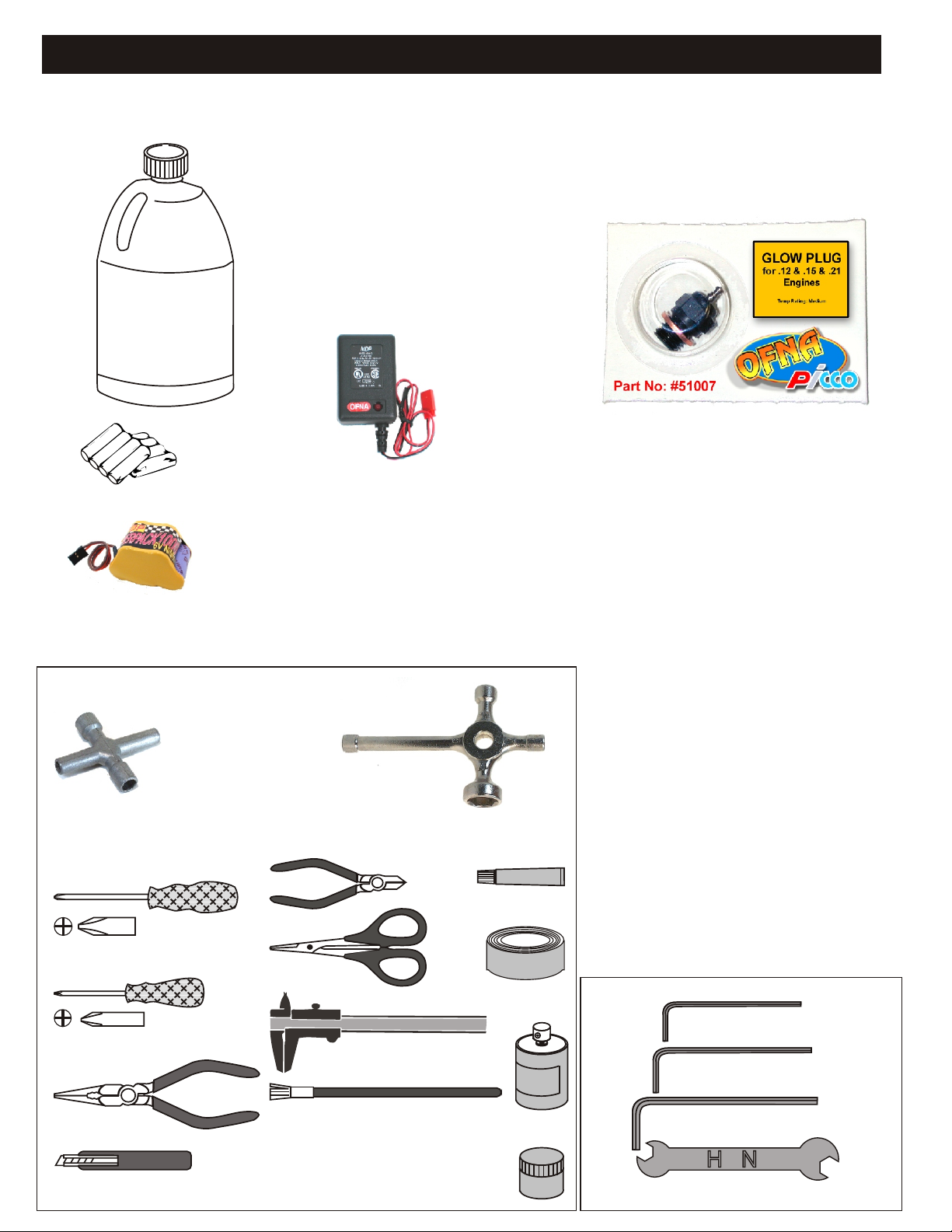
THINGS NEEDED
Glow Fuel
20%
AA Batteries ( 12 pcs )
You will need to buy a few items to start the engine and run the car.
• Use 20% nitro CAR fuel. Do not use airplane or heli fuels, they will
over heat engine.
• Buy LONG glow plugs, like OFNA/PICCO Plug (#51007 or 51008).
Use plugs without idle bar. Do NOT use plugs, like the MC-59 or OS-8
In your box you will find..
• #10162- Bottle, 250cc
• #10219 - Red “D” size glow heater
10195
7.2 Volt
Over-nite
Charger
You need to get batteries for the radio transmitter and the car receiver packs.
• Radio TX needs (8) eight AA batteries.
• Shaft Starter requires a 7.2Volt battery pack and charger OFNA #10195
• Car needs (4) four AA Ni-cad batteries 2000Mah or higher or (4) Alkaline., Alkaline type
batteries will work, but braking will be reduced and 30 minute life. The best for car, is to use a 5
cell hump receiver pack for increased voltage and longer life..
10214
Rec’v Bat.
Over-nite
Charger
#10202 Rec’v Bat.
NiHm Hump Pack,
see charger 10214.
Recommended Option:
You may want to upgrade the car battery pack to a Ni-Cad or Nimh 5 cell. This will give more
run time. OFNA #10202 1600NiMh Hump Pack and Nimh Battery Charger #10214
TOOLS NOT INCLUDED IN KIT
Cross Wrench
#17109 $3.95
Phillips Type Screw Drivers ( L )
Phillips Type Screw Drivers ( S )
Glow Plug & 17MM Cross Wrench
#10801 $6.95
Cutter
Curved Scissors
Precision Caliper
Instant Cemment
Masking Tape
INCLUDED IN KIT
1.5mm Allen Wrench
2mm Allen Wrench
Needle Nose Pliers
Knife
Brush
Paints
2.5mm Allen Wrench
4mm'5mm Allen Wrench
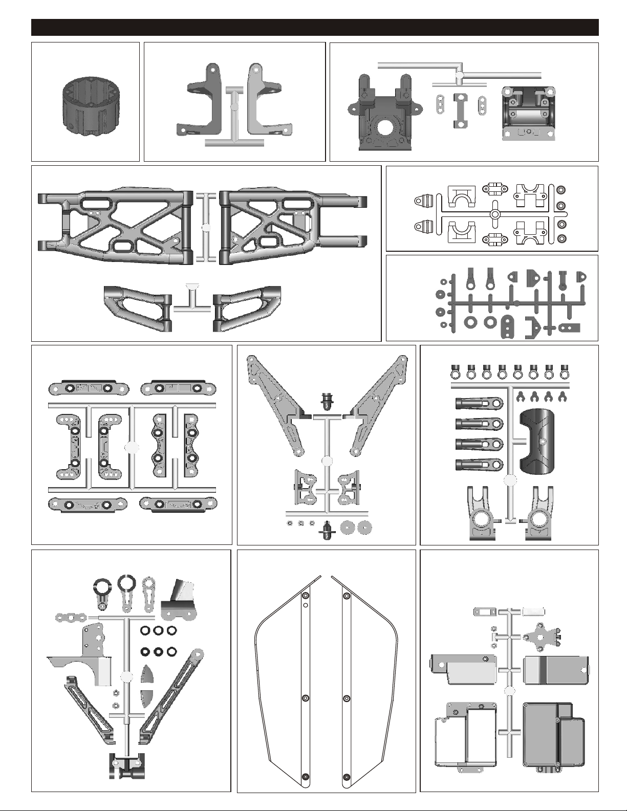
PLASTIC PARTS FOR USE
#40538
DIFF. CASE
#40535
FRONT AND REAR LOWER ARM
#40537
FRONT UPPER ARM
#40536
FRONT C HUB
#40533
FRONT AND REAR GEAR BOX
40040
CENTER DIFF. MOUNT PLASTIC PARTS
30801
Throttle Linkage
Plastic
#40534
ARM HOLDER TREE
#40539
SERVO SAVER TREE
#40542
WING MOUNT TREE
40046
STONE GUARD PLASTIC PARTS
#40540
REAR UPPER RIGHT/FRONT BUMPER TREE
#40541
RECEIVER BOX TREE

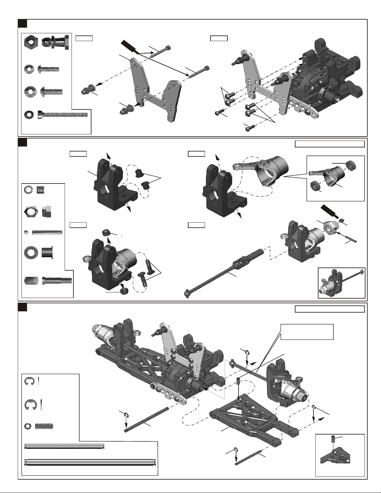
ASSEMBLY OF THE FRONT AND REAR DIFF.
1
Builds two differentials for front and rear.
#40010
2.5x13.8mm Pin
4x4mm
Set Screw
#40009
P6 O-Ring
#36053
8x16mm Ball Bearing
ASSEMBLY OF THE FRONT AND REAR DIFF.
2
..........X2
..........X1
..........X2
..........X2
Step 1
#40514
Cap Joint
#40513
Diff. Gear
(Large)
..........X2
Step 1
#30779
4x10mm
Washer
..........X4
#30779
8x16mm
Ball Bearing
#30779
4x10mm
Washer
4x4mm
Set Screw
#40010
2.5x13.8mm
Pin
#40538
Diff. Case
#40513
Diff. Gear
(Large)
#40009
P6 O-Ring
Make sure to put grease
on Diff. Outdrive shafts
#40513
Diff. Gear
(Small)
Step 2
#40513
Diff. Gear
(Large)
Step 2
#40009
P6
O-Ring
#40010
2.5x13.8mm
Pin
#40627
43T
Large
Bevel Gear
#94020
3x12mm
Flat Head
Hex Screw
#36053
8x16mm
Ball Bearing
#40514
Cap Joint
#94020
3x12mm
Flat Head
Hex Screw
#94020
3x12mm
Flat Head
Hex Screw
#40513
Diff. Gear
(Small)
#30773
4mm
Cross Pin
ASSEMBLY OF THE CENTER DIFF.
3
#40010
2.5x13.8mm Pin
#94034
4x4mm
Set Screw
#40009
P6 O-Ring
..........X4
..........X4
..........X2
..........X2
..........X1
..........X2
Step 1
#36053
8x16mm
Ball Bearing
#40515
Brake
Cap Joint
#30779
4x10mm
Washer
#40513
Diff. Gear
(Small)
#94034
4x4mm
Set Screw
#40010
2.5x13.8mm
Pin
#30773
4mm
Cross Pin
#30779
4x10mm
Washer
Step 2
#40513
Diff. Gear
(Large)
D ff
i
. O
il
Use 3000 weight diff oil in
the front and #1000 for
the rear.
Fill the Diff. case to
approx. 100% with the Diff.
Oil.
Make sure to put grease
on Diff. Outdrive shafts
#40010
2.5x13.8mm
Pin
#40009
P6
O-Ring
#40011
Diff. Gasket
#36053
8x16mm Ball Bearing
..........X2
#40513
Diff. Gear
(Large)
..........X2
#40538
Diff. Case
#40009
P6
O-Ring
#40513
Diff. Gear
(Large)
1
#40518
48T
Spur Gear
#36053
8x16mm
Ball Bearing
#40515
Brake
Cap Joint

4
ASSEMBLY OF THE CENTER DIFF.
Step 1
#30799
4x10mm
Washer
..........X4
#30779
4x10mm
Washer
#40513
Diff. Gear
(Small)
Step 2
#94020
3x12mm
Flat Head
Hex Screw
#94020
3x12mm
Flat Head
Hex Screw
#94020
Flat Head
Hex Screw
#40513
Diff. Gear
(Small)
#30773
4mm
Cross Pin
5
ASSEMBL OF THE FRONT GEAR CASEY
#40024
13x16x0.2mm
Shim
#36053
8x16mm Ball Bearing
#94011
4x16mm
Hex Screw
4x35mm
Hex Screw
..........X4
..........X4
..........X2
..........X4
..........X2
..........X2
..........X2
Step 1
#40513
Diff. Gear
(Small)
#30779
4x10mm
Washer
#40024
13x16x0.2mm
Shim
#36053
8X16mm
Ball Bearing
#40024
13x16x0.2mm
Shim
#40533
Gear Case
#30779
4x10mm
#30773
4mm
Cross Pin
#40628
13T
Small Bevel Gear
。ッAdjust the backlash
。@with the shims.
Washer
#36053
8X16mm
Ball Bearing
Diff.
Dif O
f
. il
Oil
Use 5000 weight diff. oil
Use 5000 weight diff. oil
in the center.
in the center.
Fill the Diff. Case to
Fill the Diff. Case to
approx. 80% with the Diff.
approx. 80% with the Diff.
Oil
Oil.
Step 2
#94011
4x16mm
Hex Screw
4x35mm
Hex Screw
#40011
Diff. Gasket
#40533
Gear Case
#40508
Front Lower Arm
Holder (Hard-Coated)
6
ASSEMBL OF THE FRONT ARM HOLDERSY
#94036
5x4mm
Set Screw
#94027
4x16mm
Flat Head
Hex Screw
..........X1
..........X4
Caster angle can
be changed by using
A
B
either A or B set.
We recommend
using the b caster
angle.
Steering
Characteristics
Steering becomes
milder.
Steering response
becomes quicker.
A
40534
Front Upper Arm
Holder (Rear/Plastic)
NB. use only as matched set "A" with"A"
40534
Front Lower Arm
Holder (Rear/Plastic)
Sc
C
r
ew
e
me
n
t
#94036
5x4mm
Set Screw
#40572
Universal Joint
Center (Front/Short)
#94027
4x16mm
Flat Head
Hex Screw
and "B" with "B".
4x16mm
Flat Head
Hex Screw
A
Caster
(High)
Caster
(Low)
2
ASSEMBL OF THE FRONT SHOCK STAYY
7
#40531
Shock Ball
End Post
#94003
3x10mm
Hex Screw
#94009
4x10mm
Hex Screw
#90018
3x25mm
Cap Screw
ASSEMBL OF THE KNUCKLE ARMSY
8
#90026
5x4mm
Set Screw
#94042
M4
Nylon Nut
#36055
2.5x16.8mm
Pin
..........X2
..........X2
..........X4
..........X2
..........X2
..........X4
..........X2
Step 1
#40502
Alum. Front
Shock Stay
#40531
Shock Ball
End Post
Ceme
#90018
3x25mm
S
c
rw
Cap Screw
e
nt
#90018
3x25mm
Cap Screw
Step 1 Step 2
#40536
Front C Hub
#40527
Knuckle Arm
Bushing
Step 4Step 3
#94042
Nylon Nut
Step 2
#94009
4x10mm
Hex Screw
#94003
3x10mm
Hex Screw
#94009
4x10mm
Hex Screw
Assembly for both right and left side.
#36053
8x16x5mm
Ball Bearing
#40520
Alloy Front
#40526
5mm
Alum. Wheel Hub
#36053
8x16x5mm
Ball Bearing
S
C
em
cr
ew
e
nt
Knuckle Arm
(Left)
#36055
2.5x16.8mm
Pin
#90026
5x4mm
Set Screw
#40527
Knuckle Arm
Bushing
#40528
King Screw
ASSEMBL OF THE FRONT SUSPENSION ARMS Y
9
#90020
2.5mm
E-Ring
#90021
3mm
E-Ring
#36870
4x10mm
Set Screw
#40546
X1-46 3x42.7mm Arm Shaft
#40524
X1-24 4x73mm Arm Shaft
..........X4
..........X4
..........X4
..........X4
..........X2
..........X2
..........X2
#94042
Nylon Nut
#90021
3mm
E-Ring
#40528
King Screw
#40524
4x73mm
Arm Shaft
#40535
Front Lower Arm
#90020
2.5mm
E-Ring
#40521
Universal Joint
(Front)
#90021
3mm
E-Ring
Insert the front drive shaft into
cap joint before assembly
#36870
4x10mm
Set Screw
#40546
3x42.7mm
Arm Shaft
Right side
Assembly for both right and left side.
#90020
2.5mm
E-Ring
#36870
4x10mm
Set Screw
*A 4x10mm set screw is used
to adjust ride-height.
3
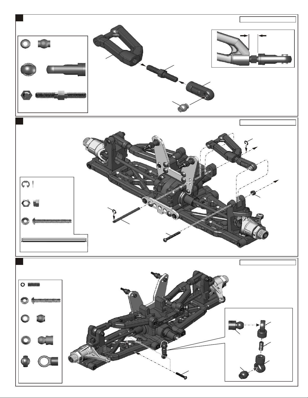
10
ASSEMBL OF THE FRONT UPPER ARMSY
Assembly for both right and left side.
#36850
7mm Ball
#36690
Front Upper
Arm Ball End
36860
G-26。@5x35mm
5x35mm
Turnbuckle
trunbuckle
11
ASSEMBL OF THE FRONT SUSPENSION ARMS Y
..........X2
..........X2
..........X2
#40537
Front Upper
Arm
#36850
7mm
Ball
#36860
5x35mm
Turnbuckle
#36690
Front Upper
Arm Ball End
8mm
。ッApprox. 7.5mm
1。G1
Assembly for both right and left side.
#90020
2.5mm
E-Ring
#90020
2.5mm
E-Ring
#34041
M3
Nylon Nut
#94008
3x25mm
Hex Screw
#40546
3x42.7mm Arm Shaft
ASSEMBL OF THE FRONT STABILIZERY
12
#94035
3x8mm
Set Screw
#94006
3x18mm
Hex Screw
#30403
6mm
Ball
#30341
Stabilizer Ball
#40540
Stabilizer
Ball End
..........X2
..........X2
..........X2
..........X2
..........X4
..........X4
..........X2
..........X2
..........X2
#90020
2.5mm
E-Ring
#40546
3x42.7mm
Arm Shaft
#94008
3x25mm
Hex Screw
#94006
3x18mm
Hex Screw
#94041
M3
Nylock Nut
Assembly for both right and left side.
Makes two rods for left and right
hand-side.
#30341
Stabilizer Ball
#30403
6mm
Ball
#40540
Stabilizer
Ball End
#94035
3x8mm
Set Screw
#40540
Stabilizer
Ball End
4

13
ASSEMBL OF THE FRONT STABILIZERY
#94033
M3x3
Set Screw
#94033
M3x3
Set Screw
#94033
M3x3
Set Screw
#94002
3x8mm
Hex Screw
#40533
Stabilizer
Mount Plastic
ASSEMBL OF THE SERVO SAVERY
14
#40539
4x8mm
Plastic Flange
Bushing
#40037
Steering Plate
Hex Screw
#40024
13x16x0.2mm
Shim
チ。ケヤ、
..........X4
..........X4
..........X2
#94033
M3x3
Set Screw
Step 1 Step 2
..........X2
..........X2
..........X2
#40533
Stabilizer
Mount Plastic
#94002
3x8mm
Hex Screw
#40510
Servo Saver
Tube
#40539
Servo Saver
Horn A
#40539
Servo Saver
Horn B
#40024
13x16x0.2
Shim
#40033
Servo Saver
Spring
#40024
13x16x0.2
Shim
#40034
Servo Saver
Spring Tension
Adjuster
#94002
3x8mm
Hex Screw
#40529
Front Stabilizer
#40037
Steering Plate
Hex Screw
#40507
Alum Servo Saver
Connecting Plate
Take the 4x8mm plastic flange bushing from
servo saver plastic parts tree .
#40539
4x8mm
Plastic Flange
Bushing
* Notice the direction of the servo saver connecting plate.
#40037
Steering Plate
Hex Screw
#40539
4x8mm
Plastic Flange
Bushing
#40539
Servo Saver
Horn C
15
ASSEMBL OF THE SERVO SAVERY
Step 1 Step 2
#94041
M3
Nylon Nut
#94003
3x10mm
Hex Screw
#94004
3x12mm
Hex Screw
#94009
4x10mm
Hex Screw
#40539
6x10mm
Plastic Bearing
..........X2
..........X1
..........X1
..........X2
..........X2
Take the 6x10mm
Ball Bearing from
X1-39 servo saver
plastic parts tree.
#40539
6x10mm
Plastic Bearing
#40539
6x10mm
Plastic Bearing
#94009
4x10mm
Hex Screw
#94003
3x10mm
Hex Screw
#40539
Servo Saver
Horn C
#40511
Servo Saver
Post
#40542
Front Body
Post
#94009
4x10mm
Hex Screw
#40506
Front Plate
#40539
6x10mm
Plastic Bearing
#40539
6x10mm
Plastic Bearing
5
M3
Nylock Nut
#40539
Center Brace
(Front)
#94041
M3
Nylock Nut
#94004
3x12mm
Hex Screw
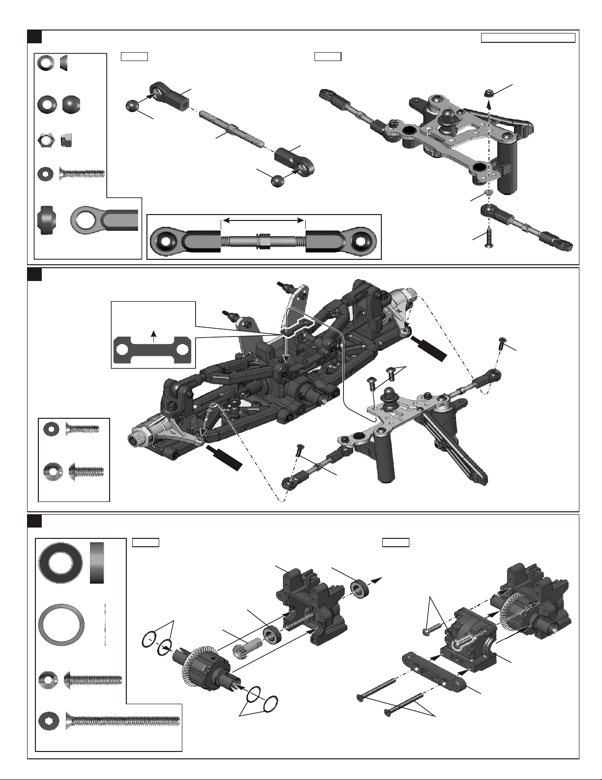
ASSEMBL OF THE STEERING TIE-RODY
16
#40039
3mm Tapper
Washer(Alum.)
..........X2
Step 1 Step 2
Makes two steering rods for left and right hand-side.
#36700
7mm Steering
Ball End
Assembly for both right and left side.
Assembly for both right and left side.
#40548
M3 Nylock Nut
(Thin Type)
#40038
7mm Ball
#94041
Nylon Nut
3x16mm
Flat Head
Hex Screw
#36700
7mm Steering
Ball End
17
ASSEMBL OF THE SERVO SAVER ONTO
..........X2
..........X2
..........X2
..........X4
Y
#40038
7mm
Ball
THE FRONT GEAR BOX
Put the front plate spacer in the
right direction.
Front
#36790
4x46mm
Turnbuckle
#40038
7mm
Ball
30 mm
#36700
7mm Steering
Ball End
1。G1
S
Cem ne
4x10mm
Hex Screw
#40039
3mm Tapper
Washer(Alum.)
3x16mm
Flat Head
Hex Screw
cr
e
w
t
3x12mm
Flat Head
Hex Screw
3x12mm
Flat Head
Hex Screw
4x10mm
Hex Screw
18
ASSEMBL OF THE REAR GEAR CASEY
#36053
8x16mm Ball Bearing
#40024
13x16x0.2mm
Shim
4x16mm
Hex Screw
4x40mm
Flat Head Hex Screw
..........X2
..........X2
..........X2
..........X4
..........X2
..........X2
Scr
C
ew
e
me
n
t
3x12mm
Flat Head
Hex Screw
Step 1 Step 2
#40024
13x16x0.2mm
Shim
#30053
8x16mm Ball Bearing
#40628
13T Small
Bevel Gear
#40024
13x16x0.2mm
Shim
#40533
Gear Case
。ッAdjust the backlash
。@with the shims.
#36053
8x16mm Ball Bearing
4x16mm
Hex Screw
4x40mm
Flat Head
Hex Screw
#40533
Gear Case
#40534
Rear Lower Arm Holder
* Take the rear lower arm holder
from #40534 Plastic Tree.
6
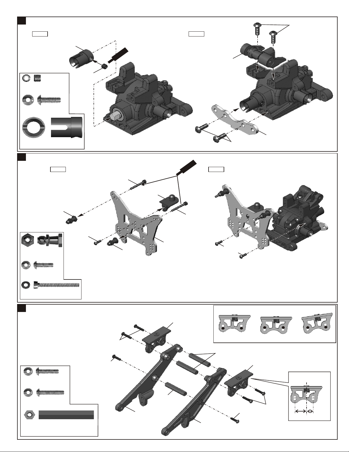
ASSEMBL OF THE REAR GEAR CASEY
19
5x4mm
Set Screw
Step 1
..........X1
#40519
Cap Joint
5x4mm
Set Screw
Sc
e
r
e
Cm
4x12mm
Hex Screw
Step 2
t
w
n
e
#40539
Center Bracer
Mount
4x12mm
Hex Screw
Cap Joint
ASSEMBLY OF THE REAR SHOCK STAY
20
..........X4
..........X1#40519
Step 1
#40531
Shock Ball End Post
one-piece/Top
3x10mm
Hex Screw
Shock Ball
End Post
3x10mm
Hex Screw
..........X2#40531
..........X3
3x25mm
Cap Screw
#40531
Shock Ball End Post
one-piece/Top
#40542
Rear body
Post
#40503
Rear
Shock stay
ew
r
Sc
Ceme t
3x25mm
Cap Screw
#40509
Rear
4x12mm
Hex Screw
n
Step 2
3x10mm
Hex Screw
Lower Arm Holder
3x25mm
Cap Screw
21
ASSEMBLY OF THE WING STAY
3x12mm
Hex Screw
3x15mm
Hex Screw
#40542
Wing Stay
Post
..........X2
..........X2
..........X4
..........X3
3x12mm
Hex Screw
3x15mm
Hex Screw
#40542
Wing Stay
Right
#40542
Wing Stay
Post
#40542
Wing Mount
7
#40542
Wing Stay
(Left)
* The install angel of the wing mount can becomes bigger or higher.
High Position
#40542
Wing Stay
Post
3x12mm
Hex Screw
Low Position
#40542
Wing Mount
3x15mm
Hex Screw
Makes two wing mounts in
the same position.
Long
Big Angle
Short

22
ASSEMBLY OF THE WING STAY
Step 1 Step 2
Nylock Nut
..........X1M3
4x16mm
Hex Screw
4x10mm
Hex Screw
Hex Screw
4x16mm
Hex Screw
23
ASSEMBLY OF THE REAR WHEEL HUBS
2.5mm
E-Ring
5X4mm
Set Screw
4x10mm
Set Screw
#36055
2.5x16.8mm Pin
#36053
8x16mm Ball Bearing
25
#405
3x48.1mm Lower Arm
..........X14x10mm
..........X5
..........X4
..........X2
..........X2
..........X2
..........X2
..........X2
4x16mm
Hex Screw
Step 1 Step 2
#40522
Rear Drive
Shat
#40540
Rear Wheel
Hub(Right )
4x16mm
Hex Screw
#36055
8x16x5mm
Ball Bearings
#36055
8x16x5mm
Ball Bearings
。ッDo not tighten
。@set screw over tighten.
#36055
2.5x16.8mm
Pin
#40526
Alum.
Wheel Hub 5mm
w
e
cr
S
em
C
5X4mm
Set Screw
* A4x10mm set screw is used
to adjust the ride heigh.
4x10mm
Set Screw
ent
#40535
Rear
Lower Arm
2.5mm
E-Ring
#40540
Wheel Base
Adjustment
Washer
#40525
3x48.1mm
Rear Lower Arm Shaft
#40539
Center Brace
(Rear)
M3
Nylock Nut
Assembly for both right and left side.
#40540
Wheel Base Adjustment
Washer
2.5mm
E-Ring
Left side
#40522
Rear Drive Shat
24
ASSEMBLY OF THE REAR SUSPENSION ARMS
3mm
E-Ring
#40524
4x73mm
Rear Lower Arm Shaft
..........X2
..........X4
..........X2
3mm
E-Ring
#40524
4x73mm
Rear Lower Arm Shaft
Assembly for both right and left side.
3mm
E-Ring
8
 Loading...