

OFNA Racing Jammin SCRT Nitro RTR User Manual
IMPORTANT-READ THIS BEFORE RUNNING
1.Before Starting
•Please read manual carefulyl (With a parent, guardian or a responsible adult if necessary).
2.While Operating
•Any running area you choose must be dry. Do not run vehicle near any water or wet areas.
•Do not run on public streets. It is very easy to have the car run over or damaged by hitting obstacles
or other surfaces.
•Do not operate the car in tight confined places. The vehicle is very fast and will easily hit something.
•Do not run near people or animals. The car is very fast and could seriously injur someone.
•Do not operate the car at night. You will not be able to drive it safely.
3.Before Operating
•Make sure that all screws and nuts are properly tightened.
•Always use fresh batteries for your transmitter and receiver before running the car. If the radio does
not have full control of the car with steering, throttle and brake. Do not run it until corrected. Failure
to correct this will result in possible injury and damage to the car or property.
We strongly recommend using a failsafe. But remember failsafe does not protect if all power is lost
in vehicle.
•Please confirm the steering and throttle is at neutral position before operating.
4.Check Your Vehicle After Runing
•On nitro vehicles engine must be shut down first before any radio equipment.
•Turn OFF receiver first, then turn OFF transmitter. This will prevent the car from losing control.
•After running radio controlled car, it is necessary to perform routine maintenance.
5 Safety
•Please be careful when handling the vehicle. It will be hot after running. Pay close attention to
engine and pipe, it is extremely hot.
WARNING: To avoid a possible fire hazard, always unplug the battery. Do not leave your vehicle
unattended.
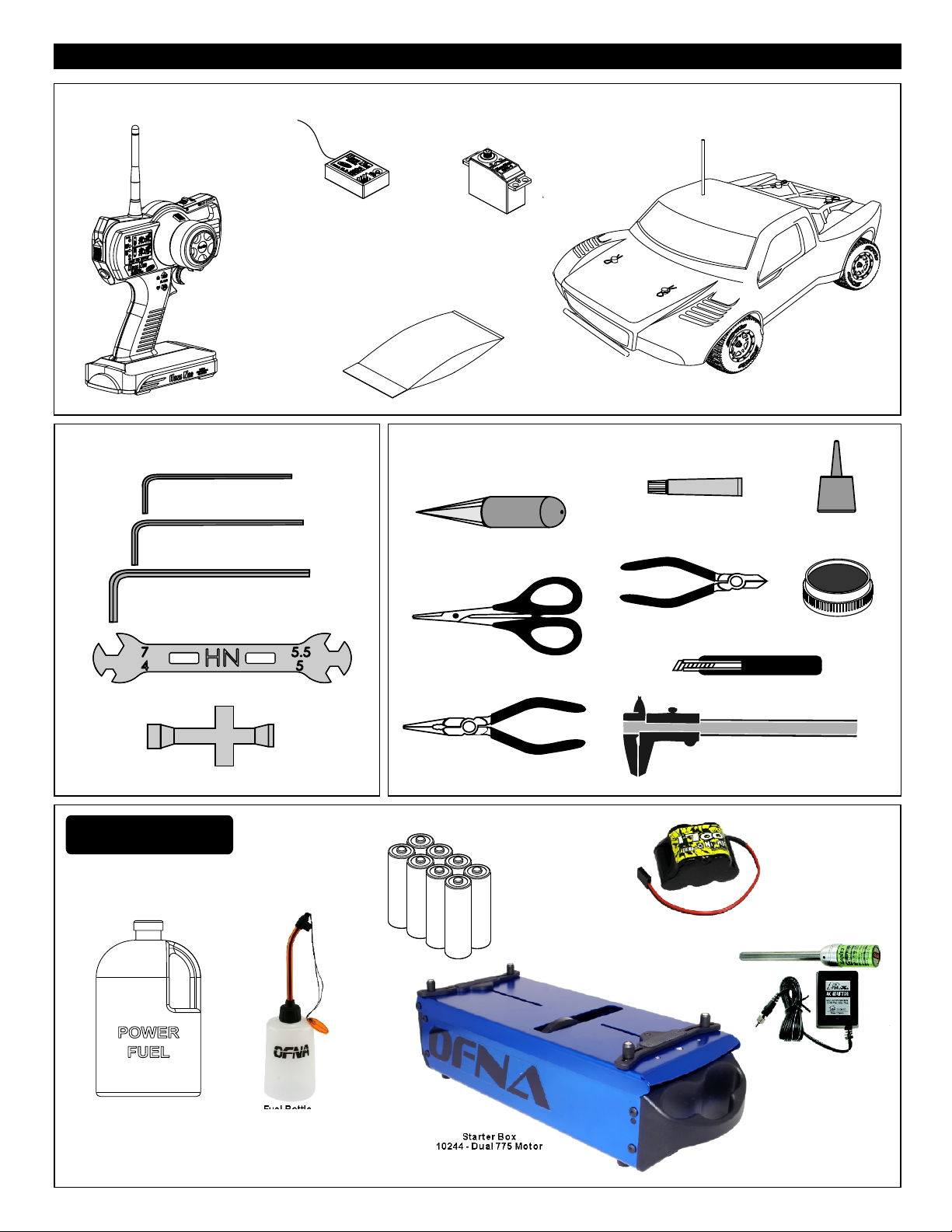
Components
OVERVIEW
Transmitter
Included Items
1.5mm Allen Wrench
2mm Allen Wrench
2.5mm Allen Wrench
Receiver
Parts Bag
Servo
TOOLS NOT INCLUDED IN THE KIT
Body Reamer
10803 - BLACK
10804 - BLUE
10805 - PURPLE
Radio Control Car
Screw Cement
Screw Cement
10289 - THREAD LOCK
CA
Instant Cemment
10239 - CA
GEAR
GREASE
Turnbuckle Wrench
Cross Wrench
Equipment Needed
OPTIONAL
Curved Scissors
91009 - LEXAN SCISSOR
Needle Nosed Pliers
AA Batteries
( 12pcs )
AA Batteries
( 4pcs )
Cutter
Craft Knife
Precision Caliper
10202 - Hump Pack 1700Mah
Gear Grease
10240 - GREEN GREASE
Glow Igniter
10215- Glow Heater
extra long with charger
Glow Fuel
NITRO 20%
Fuel Bottle
10160 - 550cc
Starter Box
10244 - Dual 775 Motor


HNT-3 2.4GHz RADIO SYSTEM OVERVIEW
HNT-3 Transmitter
*Carefully read the instruction manual of your
radio controller before using and keep it in a
safe place as a reference introduction in the
future.
1
2
3
4
5
6
7
8
10
12
14
1.Transmitter Antenna
2.Servo Reverse Switches
3.TX RF Module And Binding Button
4.Power LED
5.Power Switch
6.Steering Dual Rate Trim LED
7.External Charging Jack
8.Fail Safe Button
9.Throttle End Point Adjustment Knob
10.Steering End Point Adjustment Knob
11.Steering Dual Rate Adjustment Button
12.Steering Trim
13.Throttle Trim
14.AUX Channel Switch
9
11
Receiver Connection Diagram
Bind Button
Battery Port
Auxiliary Channel
Throttle Channel
Steering Channel
15
16
13
17
15.Steering Wheel
16.Throttle Trigger
17.Battery Cover
Specification Data
•Transmitter
Channels: 3
Frequency: 2.4Ghz
Power DC: 9.6V - 12V
Measurement: 280 x 190 x 85mm
(Packing Meas.)
Net Weight: 510g
Specification:
Channels:3Ch
Frequency:2.4GHz
DC:12V/ 8 cell AA Type
Battery
Meas.:310*170*75mm
Net weight:530g
•Receiver
Channels: 3
Frequency: 2.4Ghz
Power DC: 4.8 - 5.6V
Net Weight: 13.5g
CAUTION
• To use your Radio with your models correctly and safely, read this manual carefully and keep it in a
safe place for future reference.
Warning:
1. This product is only equipped for radio controlled cars;
2. The usage of this product should be approved by local law or regulations;
3. We will not be responsible for the damages caused by unauthorized modification, adjustment
or replacement of parts on this product;
4. The manual may be change without prior notice. Please contact us if you have any corrections
or clarifications that should be made in the manual;
• Before turning on the transmitter, make sure the transmitter batteries are fresh. The voltage of the
transmitter batteries is should never be lower than 9.6V, and please check and confirm that the servos
are all well and properly connected.
• Keep the radio system away from moist, high temperature and strong vibrations. Do not clean radio
with any solvent.
• Make sure antenna does not touch anything when power switch is turned on. Do not leave this radio
in reach of small children.
• Please use this product according to your local laws and regulations, we are not responsible for any
incidents or damages.
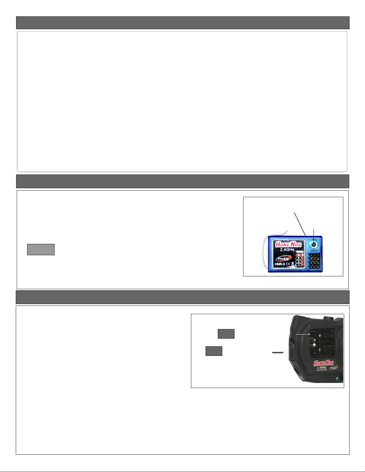
2.4Ghz Binding
•Binding your RX to Transmitter
Turn on the transmitter, then connect your speed control to the
battery, then push the bind button on the receiver while holding it
down turn on the switch on the speed control. The LED should turn
Green which means the binding is successful. After that, it’s un necessary to bind again.
LED
BIND
Caution:
When binding make sure that the RX and TX is no more
than a yard or 3 feet from each other, also no other similar FHSS
system or device is being use within 10 yard of your RX and TX
or it could accidentally pair up or bind with your vehicle.
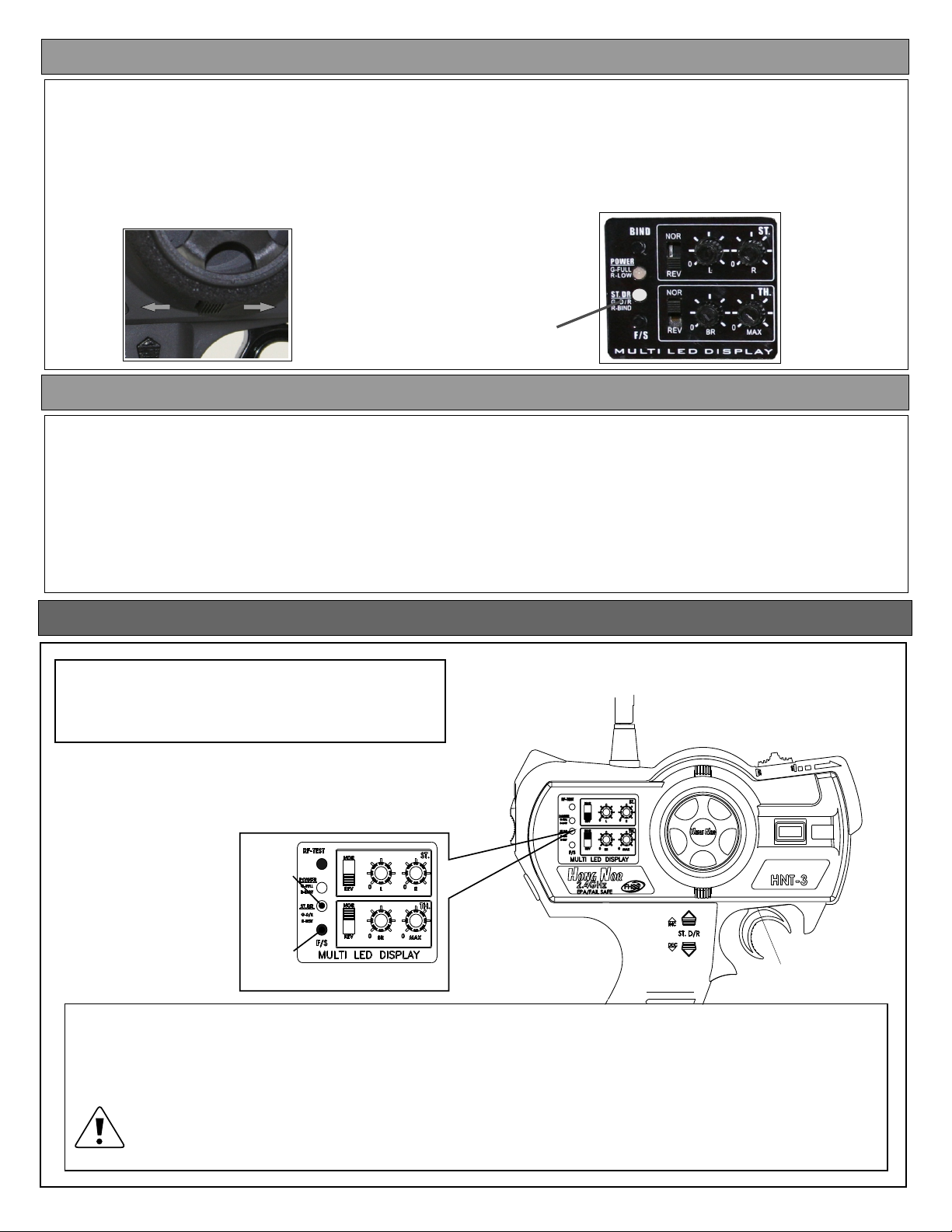
Reducing Power
• Reducing output power setting.
• Push the RF-TEST button, while holding it down turn on your transmitter,
the “ST-D/R” LED “RED” should light up. Now your output power of the
transmitter is reduce to a lower mode of 18dbm, which reduce the range
of the radio but save in battery consumption
.
•Now press the RF-TEST button again, the LED on the “ST-D/R should turn off, and
output power becomes normal 20dbm which can control your vehicle with more
range but more battery consumption.
STEP 1
STEP 2
Power Switch (turn on)
RF-TEST (Press and hold)
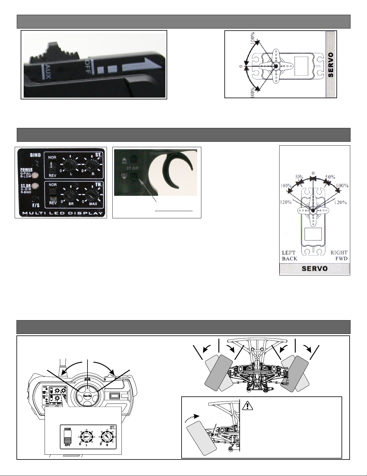
AUX Channel Function (CH3)
•This switch control the transmitter’s third channel. A servo plugged in this Channel 3 will move to full travel in one
direction when the switch is in the “AUX” position, then move the switch to the “OFF” position the servo will move
in the opposite position . This channel can be use to turn on all sort of things in your vehicle. For example, lights,
on board camera etc..... l
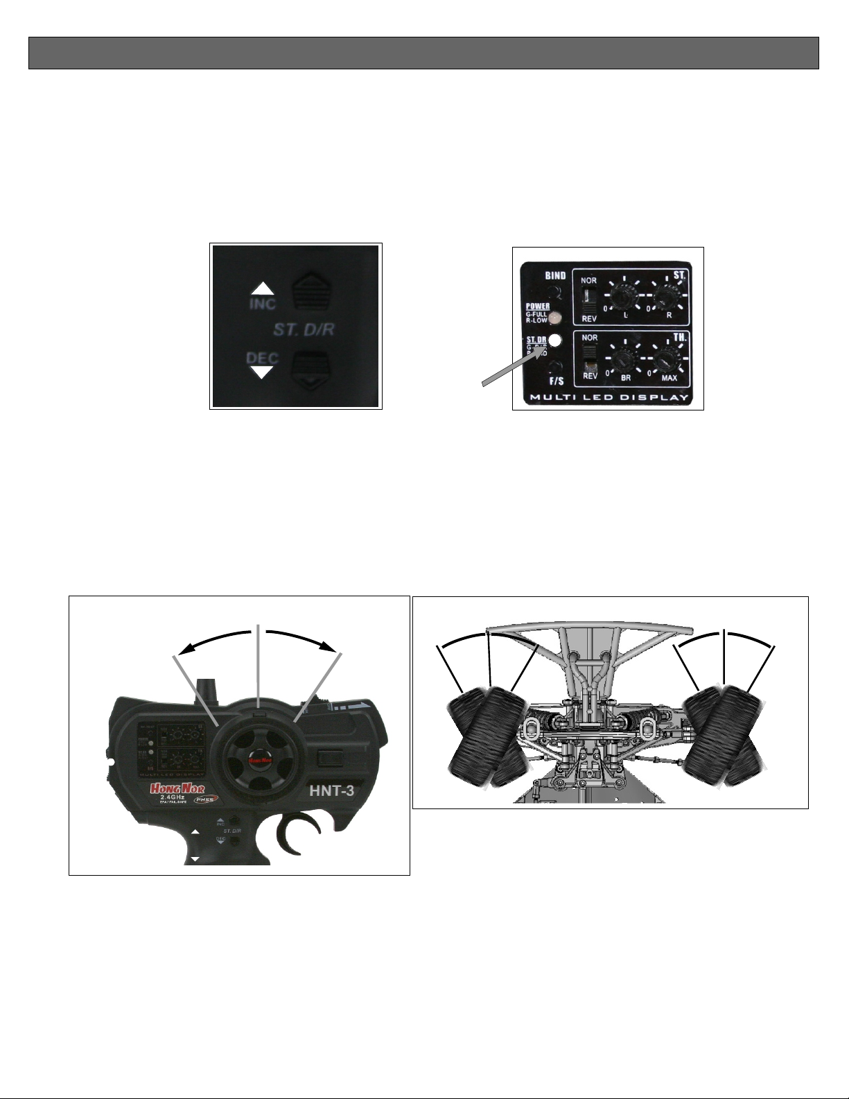
Steering Dual Rates Setup
INC
ST.DR
DEC
ST.D/R SW
•DEFINITION:
Steering Dual Rate (ST. DR): Is the adjustment that allows the dual rate value
(maximum servo travel) to be increased (INC) or decreased(DEC) with in a range
of 0% to 100% of the steering servo. This functions very useful in a race
conditions as it allows you to tailor the steering radius and sensitivity for the
current track conditions.
•ADJUSTMENT:
1.Press and hold the “INC” (Increase) button until the LED on the “ST.DR” blinking green
into a blinking red indicating maximum turning radius or value of 100%.
2.Press and hold the “DEC” (Decrease) button until the LED on the ‘ST.DR” start blinking green
and goes to a blinking red LED indicating minimum turning radius or value 0%.
Steering End Point Adjustment (EPA)
Steering End Point Adjustment (ST.EPA)
Left turn
Straight (neutral)
L R
Right turn
L R
*L/R Steering end point adjustment
(ST. EPA)knob.
Max Max
Steering
Stopper
Use the "EPA" to adjust steering tie-rod to
the steering stopper.
*After adjusting "D/R" to Max position then adjust
both "ST EPA" knob to the correct position as
picture shown.
*The steering stopper may vary for different
brand models. Follow the steering stopper
set-up for max position. The steering servo
may be damaged if it is overload.
CHECKING YOUR DUAL RATE
•To Check Your Dual Rate:
1. Turn your radio “ON” then turn “ON” your vehicle.
2. Check your steering on your radio by turning left and right several times.
3. Now turn your steering wheel all the way to the left or right whichever you choose
and hold it while pushing the “DEC” button ( see fig. 1) on the “ST-DR” and
hold it down, you should see that the wheel on your vehicle decrease in radius
(see fig. 2) and that the LED on “ST-DR” will start blinking Green and turn to a
blinking Red indicating it is at 0% or minimal steering radius
FIG. 1
INC
ST. D/R
DEC
FLASHING
.
4. To increase the dual rate turn the wheel left or right all the way and hold it while
pushing the “INC” button this will increase the turning radius of the and the LED
on ST-DR will start blinking Green and turning to the FIRST Blinking Red indicating
that the“Dual Rate” is at 80%, Holding the increase button past the FIRST Blinking
Red will turn to Blinking Green again then to the SECOND Blinking Red indicating
your “Dual Rate” is at 100%. When running your vehicle try to run the “Dual Rate”
at maximum radius (100%). Then if you have too much steering then decease as
needed.
FIG. 3
ST.DR
0%
%
0
1 0
INC
ST.D/R
DEC
1
0
0%
FIG. 2
0
0%
1
0%
1
00%
0%
%
0
10
1%
00
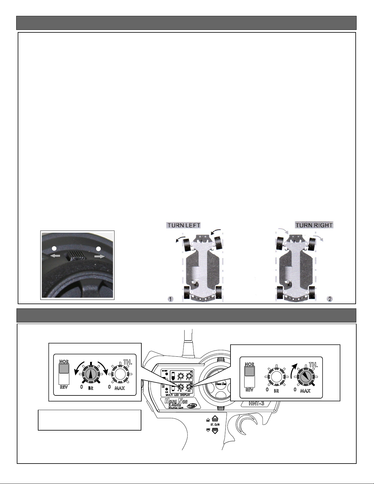
Steering Trim
Please turn on your transmitter, plug in your battery and turn on your esc while making the adjustment of these settings.
1.Connect the receivers, servos, and other components and then turn on the power switches of the transmitter and receiver.
2.Be sure the steering trim and throttle trim on the transmitter are at their neutral position.
3.When turning on your system make sure you turn on the transmitter first before turning on the receiver, while turning off the system
turn of receiver before turning off the transmitter.
•Steering Trim
Steering neutral adjustment can be made by moving the steering trim knob to the left or right.
•Finding Neutral position on the Steering
To find the center or neutral position on your transmitter, turn it on. Push the “ST-TRIM” left and notice the “ST-DR” will start flashing Green
then slowly turn to a flashing Red hold it there until you see a steady flashing Red, now you know you are at the end of left side trim. Now to
find the center or neutral position of the steering trim push the “ST-TRIM” to the right and hold it, you will notice that the “ST-DR” LED will start
flashing Green hold it their until you see that it will turn RED let go, now you are at center or neutral position, if you go past the RED light it
will start flashing GREEN again you are now off center or neutral and going toward the right.
•Racer Tip
Always check and be sure the servo is at it neutral position before installing a servo. Adjust the servo horn hole position and linkage so that
both are parallel. When a servo saver is used, place it as close to center position as possible. Be sure the steering trim on the transmitter is at
the neutral position.
•Trim Operation and Maximum Travel.
Changing the trim can effect the overall settings, when adjustments are made with the trims, please recheck your installation for maximum
servo travel. When Trim movement goes to extremes and your vehicle will not go straight.
That means if you make a lot of trim movement to get a servo to the neutral position, please reposition the servo horn or servo saver on the
servo and inspect your linkage installation.
1.When adjusting the ST-Trim button the ST-DR LED appears FLASHING GREEN.
2.When in the neutral position, the LED appears RED.
3.When in Max or Min position, LED appears FLASHING RED.
LEFT RIGHT
1
2
Throttle End Point Adjustment (EPA)
*Turn "BR" knob to set brake rate.
50%
0%
100%
100%
B
R
*We Suggest you to set the brake at 50%.
Too much brake may overheat and damage the
Electric Speed Controller and Motor.
*Turn "MAX" knob to maximize the throttle rate.
100%
M
X
A
Throttle Trim
•Throttle neutral adjustments can be made by moving the throttle trim to the left or the right.
•Racers Tip
When using a electronic speed control, please set the throttle trim to neutral and make adjustments to the speed control. On a gas powered
model, set the trim to the point where carburetor is fully closed in accordance with the engine instruction manual.
•Trim Operation and Travel
Trim adjustment will affect the overall servo travel, so please check the movement after the adjustment
When trim movement goes to extremes.
•That means if you have adjust the trim movement a lot to the neutral position, please recenter your servo horn closer to the neutral position
and inspect your throttle linkage.
Fig 5
Fig 6
Left
Reverse
Brake
Right
Forward
FLASHING
HOW TO NEUTRAL THROTTLE TRIM
•Finding Neutral position Throttle
1. Turn on transmitter
2. Push the “TH-TRIM” to the right (see Fig 5) and notice the “ST-DR” LED will start flashing Green (see Fig 6) then slowly turning to a flashing Red
hold it until you see a steady flashing Red, now you know you are at the end of the Forward trim.
3. To find the center or neutral position of the “TH-TRIM” push the “TH-TRIM” to the Left and hold it, you will notice that the “ST-DR” LED will start
flashing Green hold it their until you see that it will turn RED let go, now you are at center or neutral position, if you go past the RED light it
will start flashing GREEN again you are now off center or neutral and going toward the Reverse or Brake. If you past it don’t worry just push
it to the right a few click and you should be at neutral again.
Fail Safe Setup
•The HNT-3 radio system features a built-in fail safe to
function automatically set the servo to default when the
transmitter loses signal due to interference.
For your safety ,we recommend you to active the fail safe
function.
Fail Safe
Light
Fail Safe
button
Stop
(Neutral)
Fail Safe Process
1.Pair the transmitter and receiver before setting the fail safe(F/S) function. Turn on the transmitter power, then the receiver.
2.To set up fail safe(F/S) function with throttle servo is at neutral position, keep the throttle trigger at neutral position.
3.Press and hold the fail safe button on the transmitter for 5 second, until the fail safe LED light turn red. The fail safe(F/S) function is now
activated.
losing control of the car, the
CAUTION
•To avoid throttle servo position
must be at "neutral" when setting the fail safe(F/S) function.
• Fail safe is only good when you have power to the servo and
electronic speed control (ESC). Without power it can not go
back to neutral.
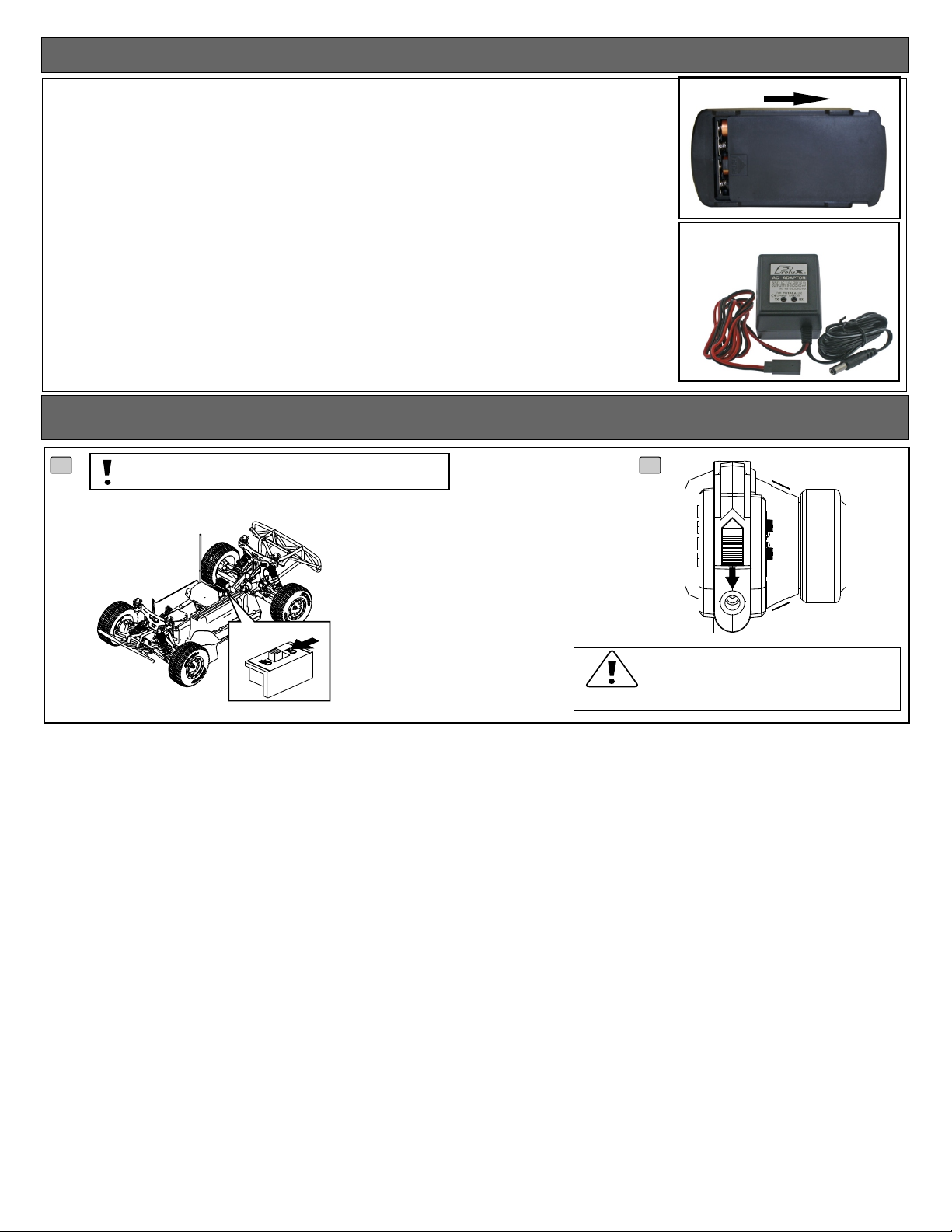
Handling Procedure For Batteries
Handling Procedure For Batteries
•Battery Replacement
1) Remove the battery cover from the transmitter by sliding it in the direction of the arrow.
2) Remove the used batteries.
3) Load the new 8 AA size alkaline, or Nickel Metal Hydride (NimH) rechargeable batteries,
and pay very close attention to the polarity marking on the batteries.
4) Slide the battery cover back onto the case.
5) If you use rechargeable batteries OFNA make this charger 10210 it will charge your Transmitter
9.6v at 100mA and Receiver battery 4.8v-6v at 100mA at the same time.
NOTICE THE DIRECTION OF BATTERY COVER
•Caution
Always make sure you reinsert the batteries are in the correct polarity order. If the batteries are loaded
incorrectly, the transmitter may not work or can be damaged.
When the transmitter is not used for a long period of time remember to remove the batteries. If the batteries
do happen to leak, clean the batteries case and contacts thoroughly and make sure the contacts are free of
corrosion.
•Battery Disposal
Some countries and state require special handling of used batteries, please contact the agencies responsible
for recycling hazardous wastes in your local area.
•Battery low voltage alarm indicator. LED Power light will flash.
Turning R/C Unit Off
1
*Turn off the receiver first, then turn off the transmitter.
OFF
CAUTION
2
*If you switch off the transmitter first
before the receiver, you may lose control
of the R/C car.
10210 - DUAL CHARGER, 4.8V-6V/9.6V TRANSMITTER AND RECEIVER
(Not included)
ON
FOR MORE SUPPORT PLEASE CALL US AT (949)586- 2910 OR CHECKOUT OUR WEBSITE
WWW.OFNA.COM .
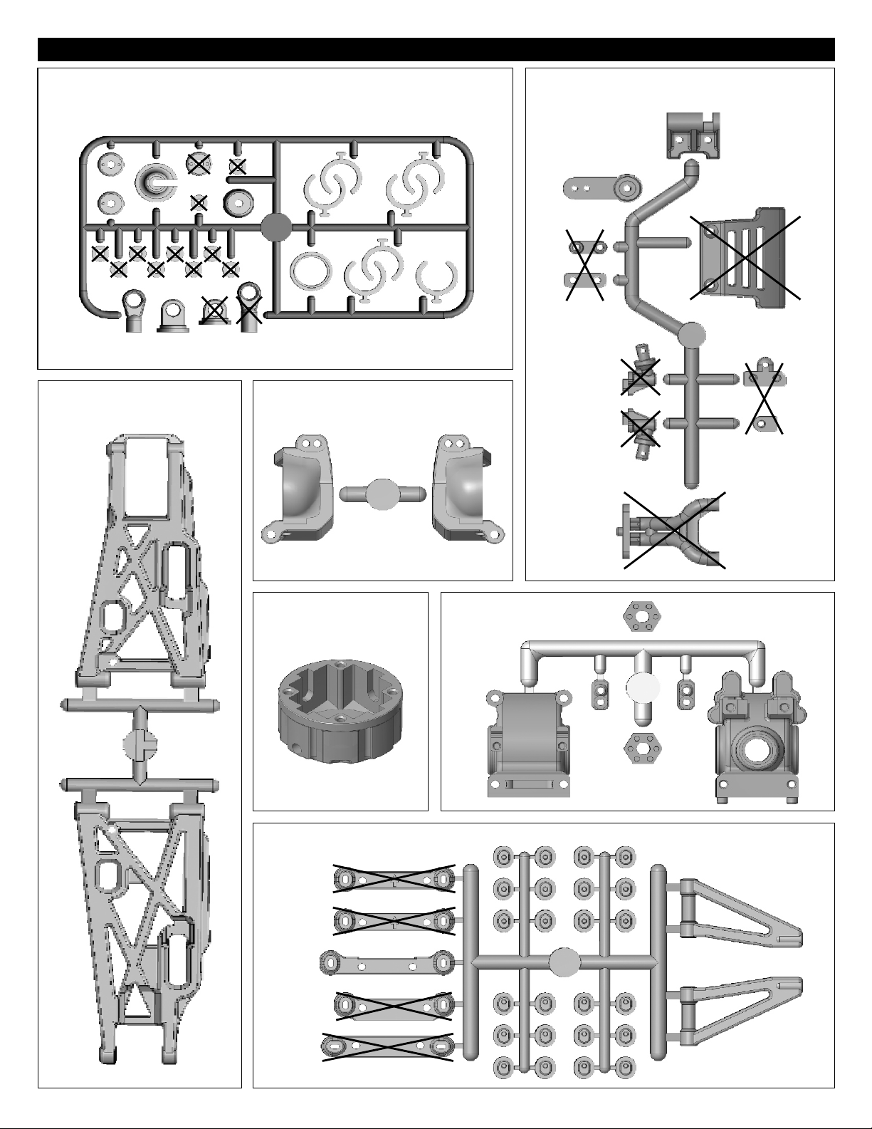
PLASTIC PARTS FOR USE
37100
SHOCK ABSORBER
40836
FRONT & REAR LOWER ARM
40839
FRONT C HUB
40921
BUMPER & RADIO TRAY POST & BODY POST
40835
DIFF. CASE
40837
FRONT UPPER ARM & ARM HOLDER
40840
FRONT & REAR GEAR BOX
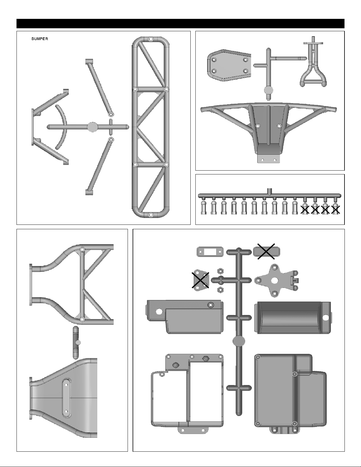
PLASTIC PARTS FOR USE
40944
REAR BUMPER
40943
FRONT BUMPER
37381
BALL END (4mm)
40945
REAR BUMPER BRACE
40541
RECEIVER BOX
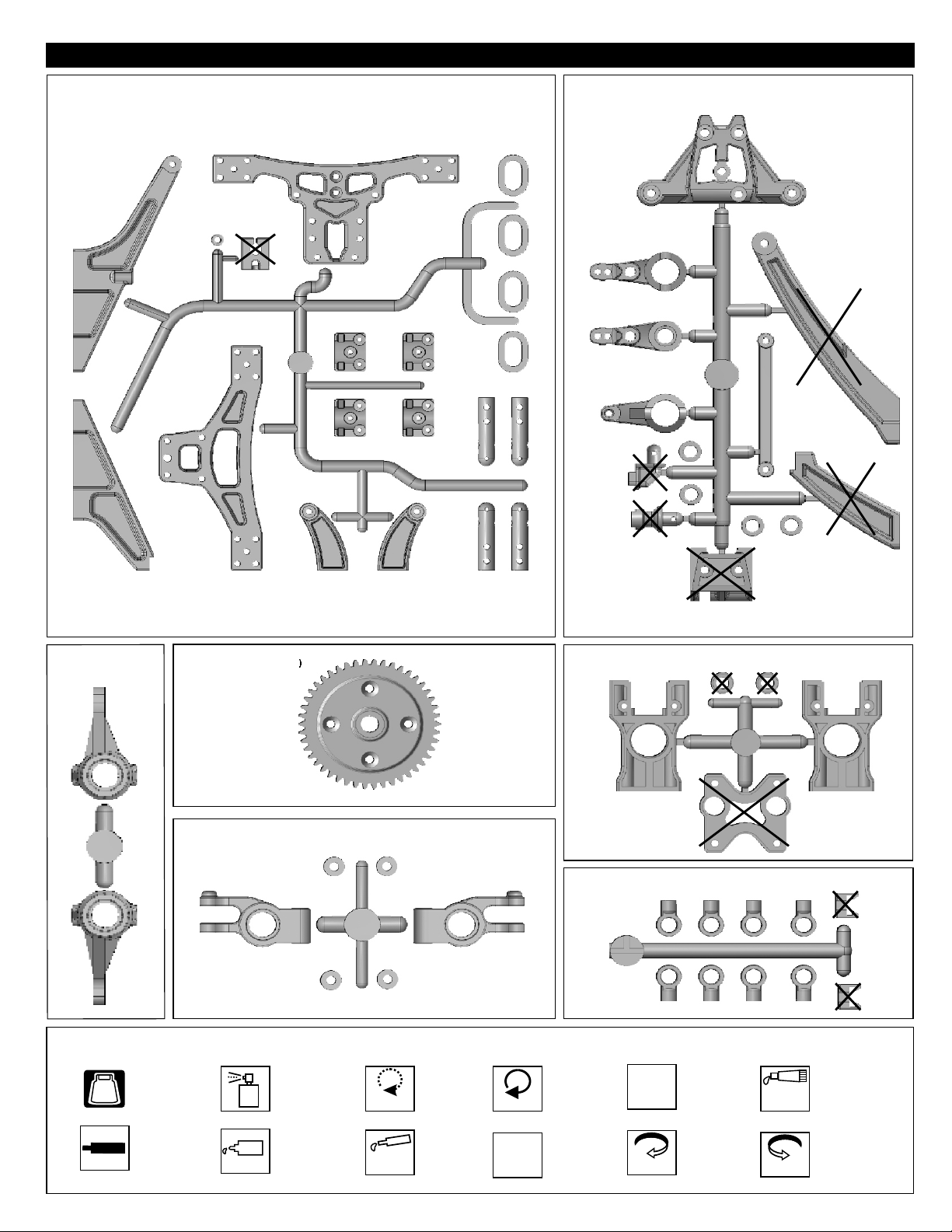
PLASTIC PARTS FOR USE
40947
BODY POST & CENTER BRACE
40834
SERVO SAVER
40841
FRONT KNUCKLEARM
40802
STEEL SPUR GEAR (46T)
40843
REAR UPRIGHT
SYMBOL USED THROUGHOUT THE INSTRUCTION MANUAL
BAG
Parts Bag Used
Degrease With
Motor Spray
Do Not
Over Tighten
Do Not
Over Tighten
Tighten
40844
CENTER DIFF. MOUNT
40848
STABILIZER BALL END
Tighten
Ensure
Free
Movement
Ensure Free
Movement
Contact
Adhesive
Contact Adhesive
Cemen
w Scre
Apply Screw
t
Cement
Apply Oil
Oil
Apply
Grease
Apply Grease
1:1
True-To-Scale
Rotate
Direction
Clockwise
Rotation
Rotate
Direction
Anti-clockwise
Rotation
 Loading...