

Page 1
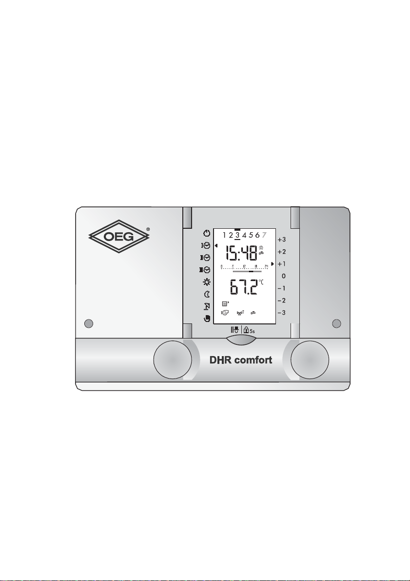
Universal heating controller
Operating manual
DHR - classic
DHR - comfort
DHR - expert
Dok. Nr. 112648 33/2010
Page 2

Operating manual
DHR - classic DHR - comfort DHR - expert
Dear User
This programmable heating controller is a modern device with a variety of
functions, enabling optimal operation of a heating system offering a very high de
gree of comfort. Most of the necessary settings are made by a technician before
the heating controller is used for the first time.
For this reason, you, the user of the heating system, should not be intimidated by
this comprehensive instruction booklet! All the information you need to op erate the
controller is in the first part of the booklet. You will find that operation of the device
is simple and logical.
Please read first the "Safety instructions" on page 7.
-
2
Dok. Nr. 112648 33/2010
Page 3
Operating manual
A B
C
D
DHR comfortDHR comfort
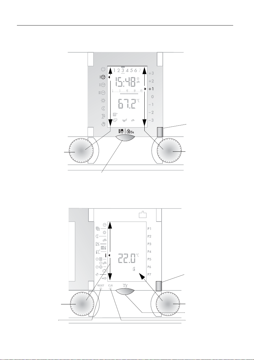
Key C
Technician key
Lock key
Selector knob A
Select
operating mode
Setting knob B
Adjust comfort
level
Toggle key D
heating circuits
(DHR comfort only)
A
C
B
D
DHR comfortDHR comfort
Selector knob A
Select functions
Setting knob B
Set and query
values
RESET key
CLR key
Toggle key D
heating circuits
(DHR comfort only)
Party key C
DHR - classic DHR - comfort DHR - expert
CONTROLS:
Functioning at User Level 1 (front cover closed)
Functioning at User Level 2 (front cover open)
3
Dok. Nr. 112648 33/2010
Page 4
Operating manual
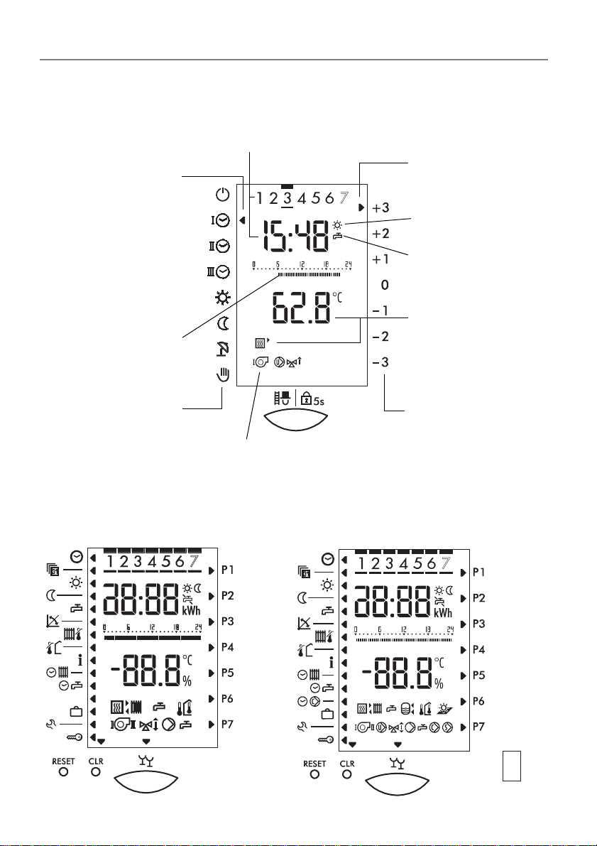
Cursor marks the
selected operating
mode
Measured value, and
the corresponding
symbol, e.g., boiler
temperature
Controller output
Time of day and day of week
Current operating
mode
Domestic hot water
charging enabled or
disabled
Temperature settings at various times
for the relevant day
Cursor marks the
selected comfort
level
Operating
modes
Comfort level
DHR - classic
DHR - comfort DHR expert
DHR - classic DHR - comfort DHR - expert
Overview of displays
The diagram shows a typical display in heating mode
(Cover closed, User Level ).
The diagram shows a display, with all the display symbols used for control.
(cover open, User Level 2.).
4
Dok. Nr. 112648 33/2010
Page 5

Operating manual
DHR - classic DHR - comfort DHR - expert
Contents
1 Safety instructions. . . . . . . . . . . . . . . . . . . . . . . . . . . . . . . . . . . . . . . . . . 7
2 Your heating controller . . . . . . . . . . . . . . . . . . . . . . . . . . . . . . . . . . . . . . 8
2.1 What the programmable controller does . . . . . . . . . . . . . . . . . . . . . . . . . . 8
2.2 User settings . . . . . . . . . . . . . . . . . . . . . . . . . . . . . . . . . . . . . . . . . . . . . . . 8
2.3 Temperature information . . . . . . . . . . . . . . . . . . . . . . . . . . . . . . . . . . . . . . 8
2.4 Effectiveness of settings . . . . . . . . . . . . . . . . . . . . . . . . . . . . . . . . . . . . . . 8
3 First operating level. . . . . . . . . . . . . . . . . . . . . . . . . . . . . . . . . . . . . . . . . 9
3.1 Selecting a heating circuit (two heating circuits) . . . . . . . . . . . . . . . . . . . . 9
3.2 Selecting an operating mode . . . . . . . . . . . . . . . . . . . . . . . . . . . . . . . . . . 10
3.3 Adjusting room temperature heating operations . . . . . . . . . . . . . . . . . . . 11
3.4 Locking . . . . . . . . . . . . . . . . . . . . . . . . . . . . . . . . . . . . . . . . . . . . . . . . . . 11
3.5 Measuring of emissions (chimney sweep service) . . . . . . . . . . . . . . . . . 12
4 Settings 2nd level (Cover open) . . . . . . . . . . . . . . . . . . . . . . . . . . . . . . 13
4.1 Unlock during error message (TEM firing automatic). . . . . . . . . . . . . . . . 14
4.2 Switching on the party function . . . . . . . . . . . . . . . . . . . . . . . . . . . . . . . . 15
4.3 Setting the time (clock). . . . . . . . . . . . . . . . . . . . . . . . . . . . . . . . . . . . . . . 15
4.4 Setting the date . . . . . . . . . . . . . . . . . . . . . . . . . . . . . . . . . . . . . . . . . . . . 16
4.5 Setting the room temperature heating mode . . . . . . . . . . . . . . . . . . . . . . 16
4.6 Setting the room temperature for night reduction heating mode . . . . . . . 17
4.7 Setting the warm water temperature . . . . . . . . . . . . . . . . . . . . . . . . . . . . 17
4.8 Adjusting the heating curve . . . . . . . . . . . . . . . . . . . . . . . . . . . . . . . . . . . 18
4.9 Setting the maximum supply temperature . . . . . . . . . . . . . . . . . . . . . . . . 19
4.10 Setting the heating limit (summer/winter) . . . . . . . . . . . . . . . . . . . . . . . . 19
4.11 Displaying the controller output ports. . . . . . . . . . . . . . . . . . . . . . . . . . . . 20
4.12 Displaying temperatures and values . . . . . . . . . . . . . . . . . . . . . . . . . . . . 21
4.12.1 Set values and actual values . . . . . . . . . . . . . . . . . . . . . . . . . . . . 22
4.13 Transfer the value to the standard display (1st level) . . . . . . . . . . . . . . . 22
4.14 The standard clock programs (factory settings). . . . . . . . . . . . . . . . . . . . 23
4.14.1 Cooperation of the standard and the individual D.H.W.
clock program (Example). . . . . . . . . . . . . . . . . . . . . . . . . . . . . . . . . . . . . 24
4.14.2 Reload of standard clock programs preset at the factory 25
4.15 Setting the clock programs for heating/D.H.W. . . . . . . . . . . . . . . . . . . . . 26
4.15.1 Checking the clock program for heating/D.H.W. mode. . . . . . . . . 26
4.15.2 Changing the clock program for heating/D.H.W mode . . . . . . . . . 26
4.16 Setting an individual D.H.W. clock program P1 . . . . . . . . . . . . . . . . . . . 28
4.16.1 Separating the clock program D.H.W. from the standard
clock program heating . . . . . . . . . . . . . . . . . . . . . . . . . . . . . . . . . . . . . . . 28
4.16.2 Display and change the individual D.H.W. clock program . . . . . . 29
Dok. Nr. 112648 33/2010 5
Page 6

Operating manual
DHR - classic DHR - comfort DHR - expert
4.17 Setting the circulation pump clock program P1. . . . . . . . . . . . . . . . . . . . 29
4.17.1 Display and change the circulation pump clock program . . . . . . . 29
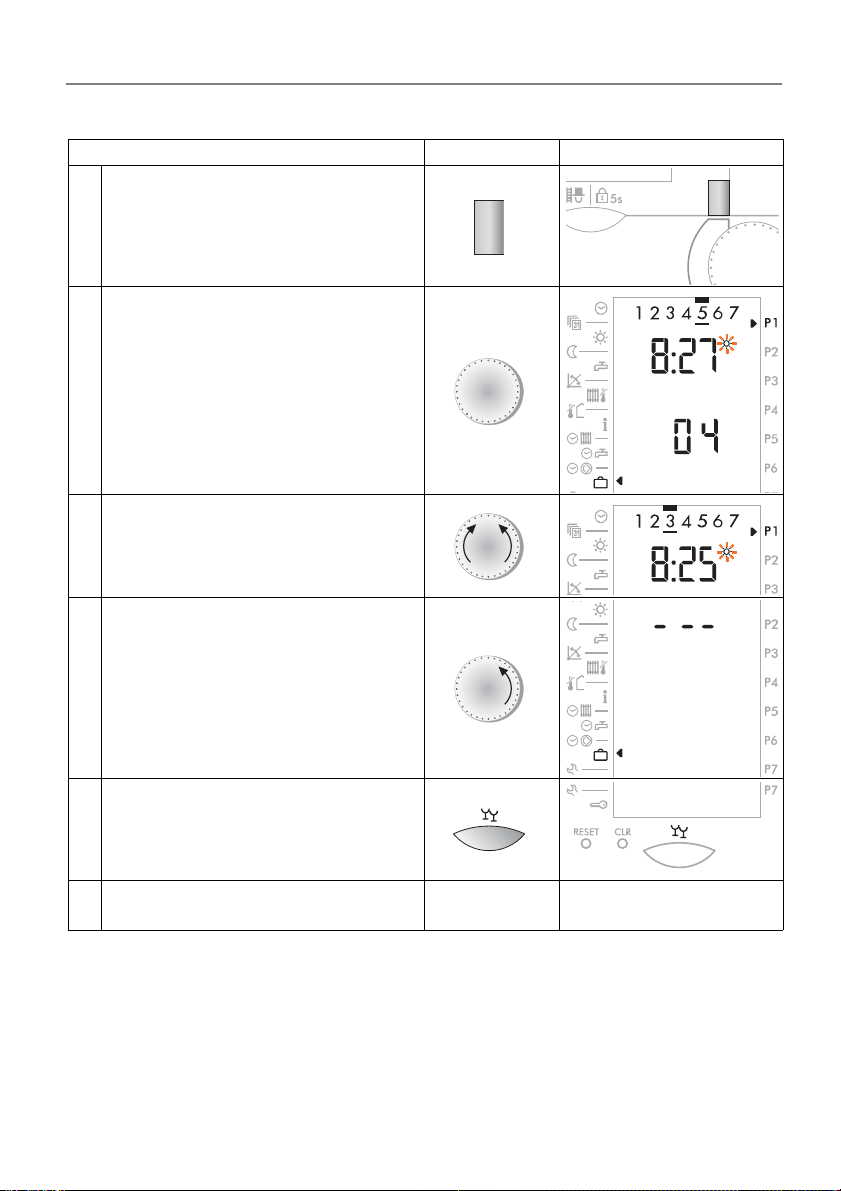
4.18 Vacation program . . . . . . . . . . . . . . . . . . . . . . . . . . . . . . . . . . . . . . . . . . 30
4.18.1 Setting the vacation program . . . . . . . . . . . . . . . . . . . . . . . . . . . . 30
4.18.2 Vacation program display/change/terminate. . . . . . . . . . . . . . . . . 31
5 Service level . . . . . . . . . . . . . . . . . . . . . . . . . . . . . . . . . . . . . . . . . . . . . . 32
5.1 Query operating data . . . . . . . . . . . . . . . . . . . . . . . . . . . . . . . . . . . . . . . . 32
5.2 Switching output functions on and off . . . . . . . . . . . . . . . . . . . . . . . . . . . 33
5.3 3. Level. . . . . . . . . . . . . . . . . . . . . . . . . . . . . . . . . . . . . . . . . . . . . . . . . . . 34
5.4 Error message . . . . . . . . . . . . . . . . . . . . . . . . . . . . . . . . . . . . . . . . . . . . . 35
5.4.1 General information. . . . . . . . . . . . . . . . . . . . . . . . . . . . . . . . . . . . . 35
6 Definitions. . . . . . . . . . . . . . . . . . . . . . . . . . . . . . . . . . . . . . . . . . . . . . . . 36
7 Index . . . . . . . . . . . . . . . . . . . . . . . . . . . . . . . . . . . . . . . . . . . . . . . . . . . . 37
6
Dok. Nr. 112648 33/2010
Page 7

Operating manual
DHR - classic DHR - comfort DHR - expert
1 Safety instructions
Regulatory compliance and safety information
This programmable controller is a moder n elec tr o nic device.
This equipment complies with the following EC Directives:
• 73/23/EEC "Low Voltage Directive"
• 89/336/EEC "Electro-Magnetic Compatibility (EMC) Directive", including
amendment 92/31/EEC
The device is designed to be used with a heating appliance in accordance with the
manufacturer's specifications.
No other type of usage is permitted.
Safety
This device uses state-of-the-art technology and confor ms to the relevant safety
regulations.
Danger
The device is electrically operated. Incorrect installation, or attempts by non-specialists to repair the device, may result in electric shocks, with fatal consequences.
Installation and commissioning may be carried out only by appropriately qualified
technical personnel. In general, the device and its accessories should not be ope
ned up. Repairs should be carried out only by the manuf ac tur e r.
-
Instructions in this booklet that are marked with a warning symbol must
be observed.
Dok. Nr. 112648 33/2010 7
Page 8

Operating manual
DHR - classic DHR - comfort DHR - expert
2 Your heating controller
2.1 What the programmable controller does
When correctly programmed, the device works in conjunction with an appropriate
heating system to ensure that heating to the required temperature occurs during
the programmed time-intervals. The available boilers (different forms of energy)
are used environmental carefully and efficiently according to the necessary heat
requirement.
2.2 User settings
As user, you can make the following settings:
• 3.1 Selecting a heating circuit (two heating circuits), page 9
• 3.2 Selecting an operating mode, page 10
• 3.3 Adjusting room temperature heating operations, page 11
• 3.4 Locking, page 1 1
• 4.2 Switching on the party function, page 15
• 4.3 Setting the time (clock), page 15
• 4.5 Setting the room temperature heating mode, page 16
• 4.6 Setting the room temperature for night reduction heating mode, page 17
• 4.7 Setting the warm water temperature, page 17
• 4.8 Adjusting the heating curve, page 18
• 4.9 Setting the maximum supply temperature, page 19
• 4.10 Setting the heating limit (summer/winter), page 19
• 4.12 Displaying temperatures and values, page 21
• 4.15 Setting the clock programs for heating/D.H.W., page 26
• 4.16 Setting an individual D.H.W. clock program P1, page 28
• 4.17 Setting the circulation pump clock program P1, page 29
All other adjustments should be made by technical personnel only.
Faulty adjustments may lead to malfunctioning o f the heating system
or may shorten its life.
2.3 Temperature information
All temperature information is:
• if measured, in °C (Celsius)
• as temperature difference in K (Kelvin)
2.4 Effectiveness of settings
• 1. level: Modified settings become immediately effective
• 2. level: Modified settings become effective by changing the parameter or by
closing the cover
8
Dok. Nr. 112648 33/2010
Page 9
Operating manual
DHR - classic DHR - comfort DHR - expert
3 First operating level
3.1 Selecting a heating circuit (two heating circuits)
The corresponding heating circuit must be selected each time before a function
can be carried out. Depending on the heating circuit selected, the switch key
shows either "red" or "green".
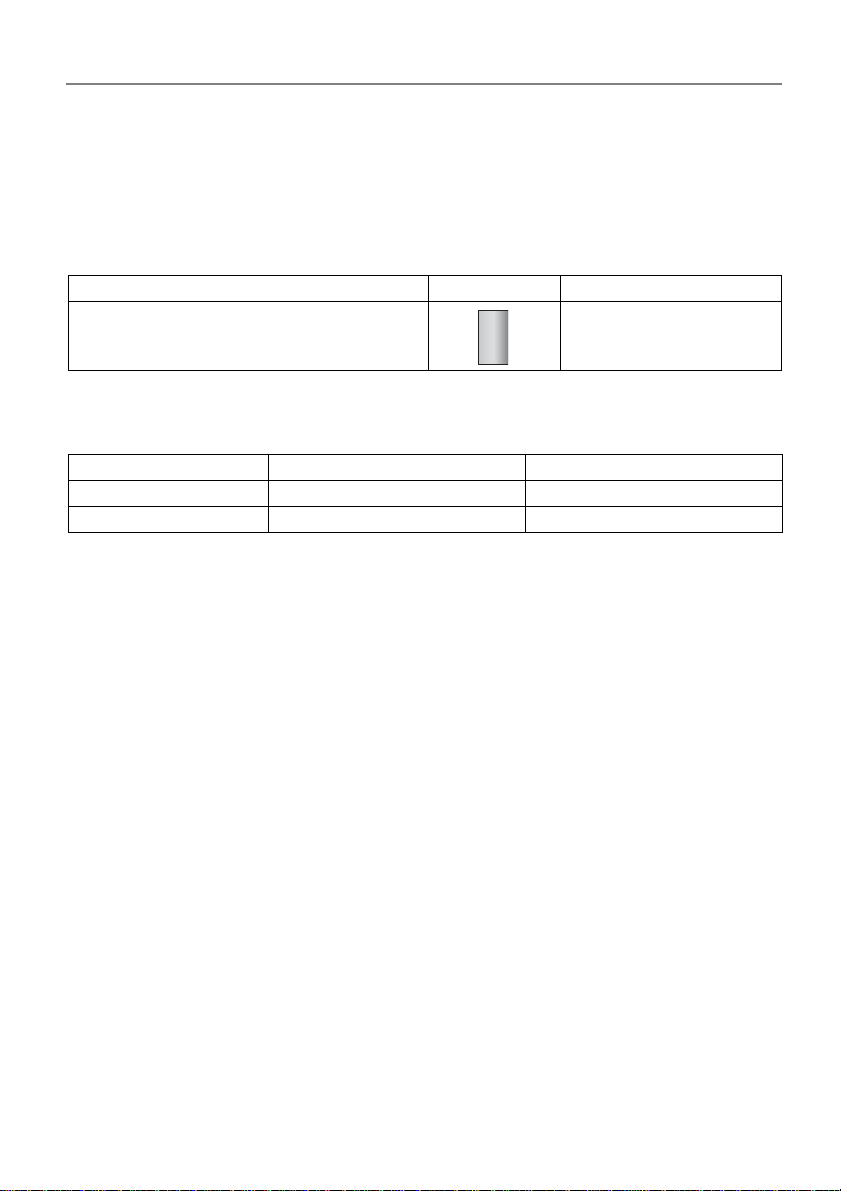
Operating step Operation Display
Press the key D to select the correct
heating circuit "green" or "red"!
Your heating expert can tell you which colour refers which heating circuit.
This can then be noted here:
Note reference:
Heating circuit
Generator
1 (green) 2 (red)
D
Standard display D
appears
Dok. Nr. 112648 33/2010 9
Page 10
Operating manual
DHR - classic DHR - comfort DHR - expert
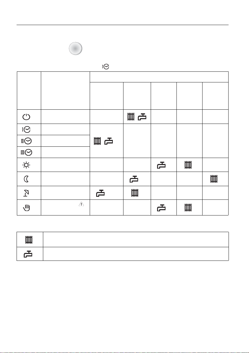
3.2 Selecting an operating mode
Set using the knob
A
The arrow to the left in the display shows the selected operating mode.
Example front view: The setting becomes valid immediately.
Explanation
Symbol Operating mode
Heating OFF
(Standby)
Clock program I
Clock program II
Clock program III
Heating mode
Reduced heating
mode
Summer mode
Manual mode
Emergency mode
in accordance
with clock program
(1
continuously OFF
(1
continuously ON
continuous
heating
mode
continuous
reduction
mode
Legend:
Heating mode
Domestic hot water mode
Note: In all operating modes the freeze protection is guaranteed.
Heating limits can switch the heating enterprise off.
On operating mode "Manual/Emergency" please call the specialist.
1) you can define your own domestic hot water-heating program.
10
Dok. Nr. 112648 33/2010
Page 11
Operating manual
5 seconds
5 seconds
DHR - classic DHR - comfort DHR - expert
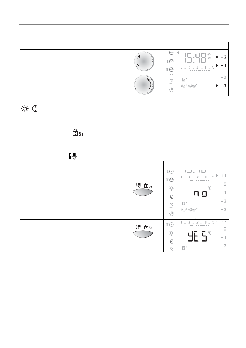
3.3 Adjusting room temperature heating operations
Operation step Operation Display
Ambient temperature increase
Example: +1.5 °C
Ambient temperature decrease
Example: - 3,0 °C
(save, absence)
The arrows to the right in the display show the adjusted temperature settings for
heating . The adjustment becomes valid immediately.
B
B
3.4 Locking
The lock prevents unintentional changes of settings. The lock applies to both heating circuits/boilers at the same time and includes all functions, except "measu-
ring of emissions" .
Operation step Operation Display
Activate lock
C
Deactivate look
Dok. Nr. 112648 33/2010 11
C
Page 12
Operating manual
DHR - classic DHR - comfort DHR - expert
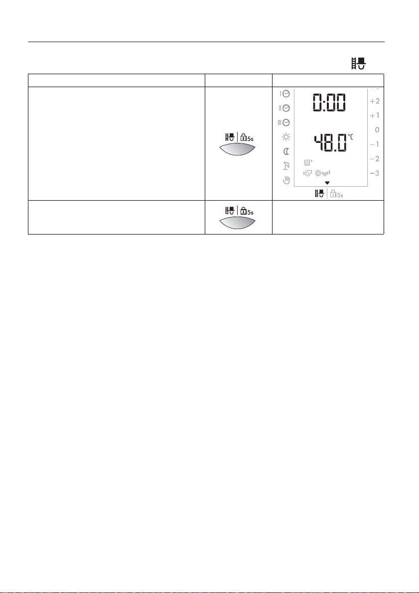
3.5 Measuring of emissions (chimney sweep service)
Operation step Operation Display
Activate emission measurement
Deactivate emission measureme nt
Note: Following activation of this function, heating is controlled according to the
set maximum temperature. Operation of this function for measuring emissions is
limited to 20 minutes and must be reactivated after this time if required.
C
C
Standard display
1st level appears
12
Dok. Nr. 112648 33/2010
Page 13
Operating manual
DHR - classic DHR - comfort DHR - expert
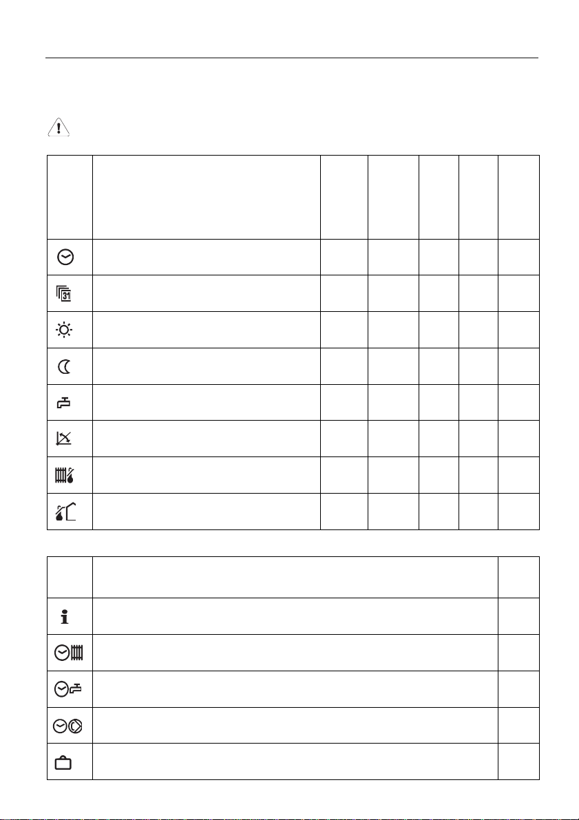
4 Settings 2nd level (Cover open)
Incorrect changes to the settings may cause the heating system to
malfunction or shorten its life.
Symbol
Symbol
Function to be set
Factory
settings
Setting
range
Basic
adjustment
Adjustment
"Setting the time (clock)"; page 15
"Setting the date"; page 16
"Setting the room temperature heating
mode"; page 16
"Setting the room temperature for night
reduction heating mode"; page 17
"Setting the warm water temperature";
page 17
"Adjusting the heating curve"; page 18 1.2 0.0÷5.0 "Setting the maximum supply tempe-
rature"; page 19
"Setting the heating limit (summer/win-
ter)"; page 19
pre-
sent *
pre-
sent *
20 10÷30 °C
15 5÷20 °C
55 10÷70 °C
70 10÷90 °C
18 0÷40 °C
- h/m
until
2079
M/T/J
Function to be set
Unit
Unit
"Displaying temperatures and values"; page 21 °C
"The standard clock programs (factory settings)"; page 23
"Setting the clock programs for heating/D.H.W."; page 26
"Setting an individual D.H.W. clock program P1"; page 28 -
"Setting the circulation pump clock program P1"; page 29 -
"Vacation program"; page 30 -
Dok. Nr. 112648 33/2010 13
-
Page 14
Operating manual
D
C
C
DHR - classic DHR - comfort DHR - expert
Symbol
RESET
CLR
Function to be set
Service level Access code
For technicians only
"Switching on the party function"; page 15
An active vacation program is deleted
Restarts the controller. No settings are changed! -
• "Transfer the value to the standard display (1st level)"; page 22
• "Reload of standard clock programs preset at the factory"; page 25
• Reset the operational data , see
"5.1 Query operating data", page 32
Unit
-
-
-
* Clock reserve PM 2970/72 = 24h; PM 2975 = 2 years
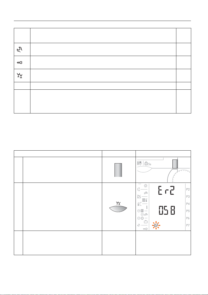
4.1 Unlock during error message (TEM firing automatic)
If a firing automatic of a solid boiler is integrated in the plant, a possible error message can be acknowledged.
Operation step Operation Display
1 Select generator
D
Open front cover
Unlock:
2
Keep the key C pressed until the
burner symbol lights up briefly.
If the error was successfully repaired, the controller turns back to the
3
standard display within max. 3
minutes.
14
Close cover
Standard display
1st level appears
Dok. Nr. 112648 33/2010
Page 15
Operating manual
C
Stunden
Minuten
DHR - classic DHR - comfort DHR - expert
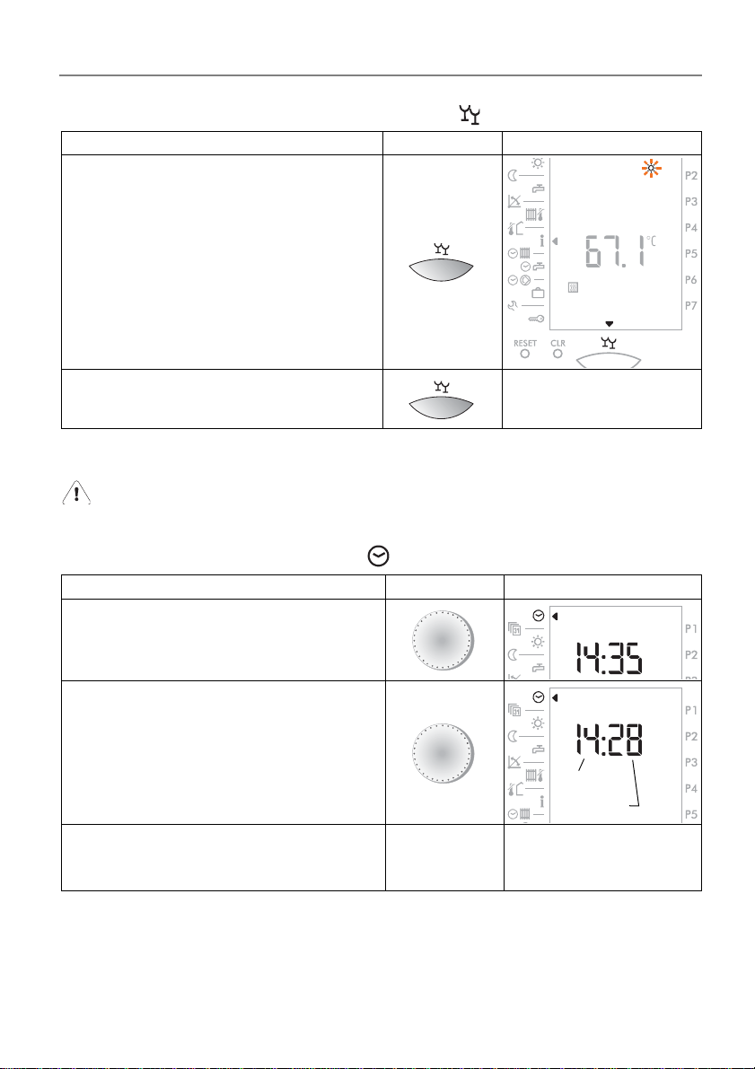
4.2 Switching on the party function
Operation step Operation Display
Activate party function
Deactivate party function
Note: The party function becomes valid for 3 hours from the start of the next
night reduction heating phase according to clock program.
An active vacation program is by activating the party function de-
leted!
C
Standard display
1st level appears
4.3 Setting the time (clock)
Operation step Operation Display
Select the function
Set the time
Select another function
or close the cover
The setting is stored
Note: Change from win ter time to summer time, an d vi ce versa, is made au-
tomatically on the last Sunday of March and again in October. If the
controller is not connected to the line, no automatically change hap
pens. As soon as the controller is connected to th e line , cha n ge happens the following day between 2.00 and 3.00 o‘clock a.m.
A
B
The selected function or
the standard display
appears
-
Dok. Nr. 112648 33/2010 15
Page 16

Operating manual
A
Year
Month
Day
Day
B
DHR - classic DHR - comfort DHR - expert
4.4 Setting the date
A calendar program is available. This is programmed to the year 2099, and takes
leap years into account.
Operation step Operation Display
Select date
Example: October 24, 2003
Set the date
Example: November 09, 2003
Select another function
or close the cover
The setting is stored
Note: On setting the date, the day of the week is indicated as follows:
1 = Monday, 2 = Tuesday, 3 = Wednesday, 4 = Thursday, 5 = Friday,
6 = Saturday, 7 = Sunday
The selected function or
the standard display
appears
4.5 Setting the room temperature heating mode
Operation step Operation Display
Select function
Set the selected room temperature.
Example: Heating 20.0 °C
The setting becomes valid immediately!
Select another function
or close the cover
The setting is stored
16
A
B
The selected function or
the standard display
appears
Dok. Nr. 112648 33/2010
Page 17
Operating manual
DHR - classic DHR - comfort DHR - expert
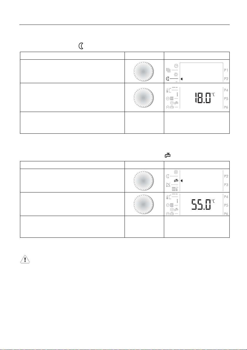
4.6 Setting the room temperature for night reduction heating mode
Operation step Operation Display
Select function
Set the room temperature for night
reduction heating.
Example: reduced heating 18.0 °C
The setting becomes valid immediately!
Select another function
or close the cover
The setting is stored
A
B
The selected function or
the standard display
appears
4.7 Setting the warm water temperature
Operation step Operation Display
Select function
Set the domestic warm water
temperature.
Example: DHW 55.0 °C
Select another function
or close the cover
The setting is stored
The warm water boiler is now controlled by this temperatur e.
A
B
The selected function or
the standard display
appears
Changes should be discussed with a qualified technician.
Dok. Nr. 112648 33/2010 17
Page 18
Operating manual
A
B
DHR - classic DHR - comfort DHR - expert
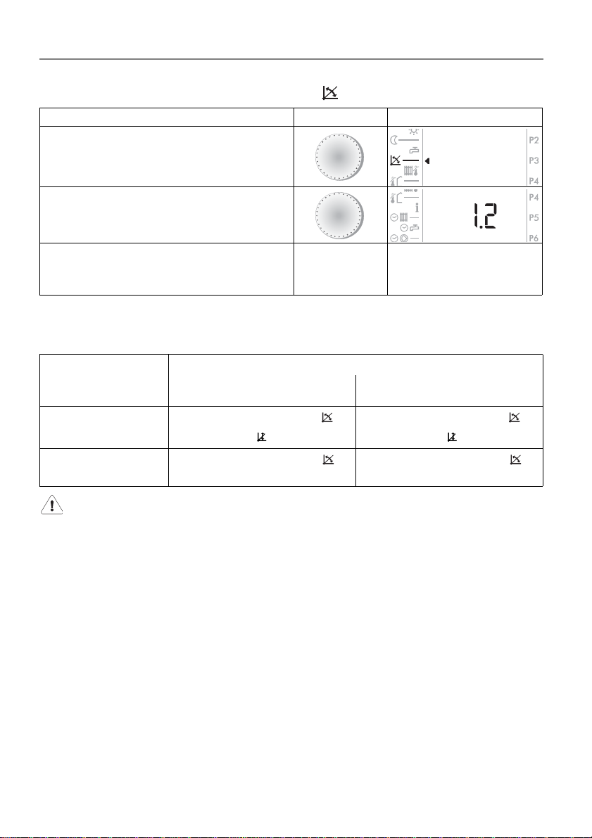
4.8 Adjusting the heating curve
Operation step Operation Display
Select function
Set the heating curve.
Example: Heating curve 1.2
Select another function
or close the cover
The setting is stored
The selected function or
the standard display
appears
Due to the deviation of room temperature to outside temperature each time, changes should be made as follows:
Outside
temperature
during the day
+5 until +15 °C
-20 until +5 °C
too cold too warm
Set slope of heating curve to
- 0.2 and base to + 5 K.
Set slope of heating curve
to + 0.2
Room temperature
Set slope of heating curve to
+ 0.2 and base to - 5 K.
Set slope of heating curve
to - 0.2.
Changes are only processed slowly by the building. For this reason,
only one change should be made per day.
18
Dok. Nr. 112648 33/2010
Page 19
Operating manual
DHR - classic DHR - comfort DHR - expert
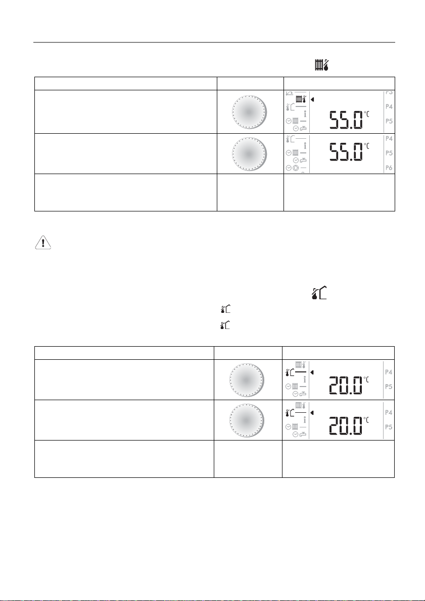
4.9 Setting the maximum supply temperature
Operation step Operation Display
Select function
Set the maximum supply temperature.
Example: maximum supply tempera-
ture 55 °C
Select another function
or close the cover
The setting is stored
The maximum supply temperature is limited to the set value.
This is not a safety feature. Safety (protection against overheating)
must be ensured by a qualified technician.
A
B
The selected function or
the standard display
appears
4.10 Setting the heating limit (summer/winter)
Average outside temperature is upper as = heating "OFF"
Average outside temperature is lover as ( - 2 K) = heating "ON"
Operation step Operation Display
Select function
A
Set the heating limit.
Example: heating limit 20 °C
Select another function
or close the cover
The setting is stored
Note: The heating limit in night reduction period can be adjusted on the
setting 3-2.
Dok. Nr. 112648 33/2010 19
B
The selected function or
the standard display
appears
Page 20
Operating manual
DHR - classic DHR - comfort DHR - expert
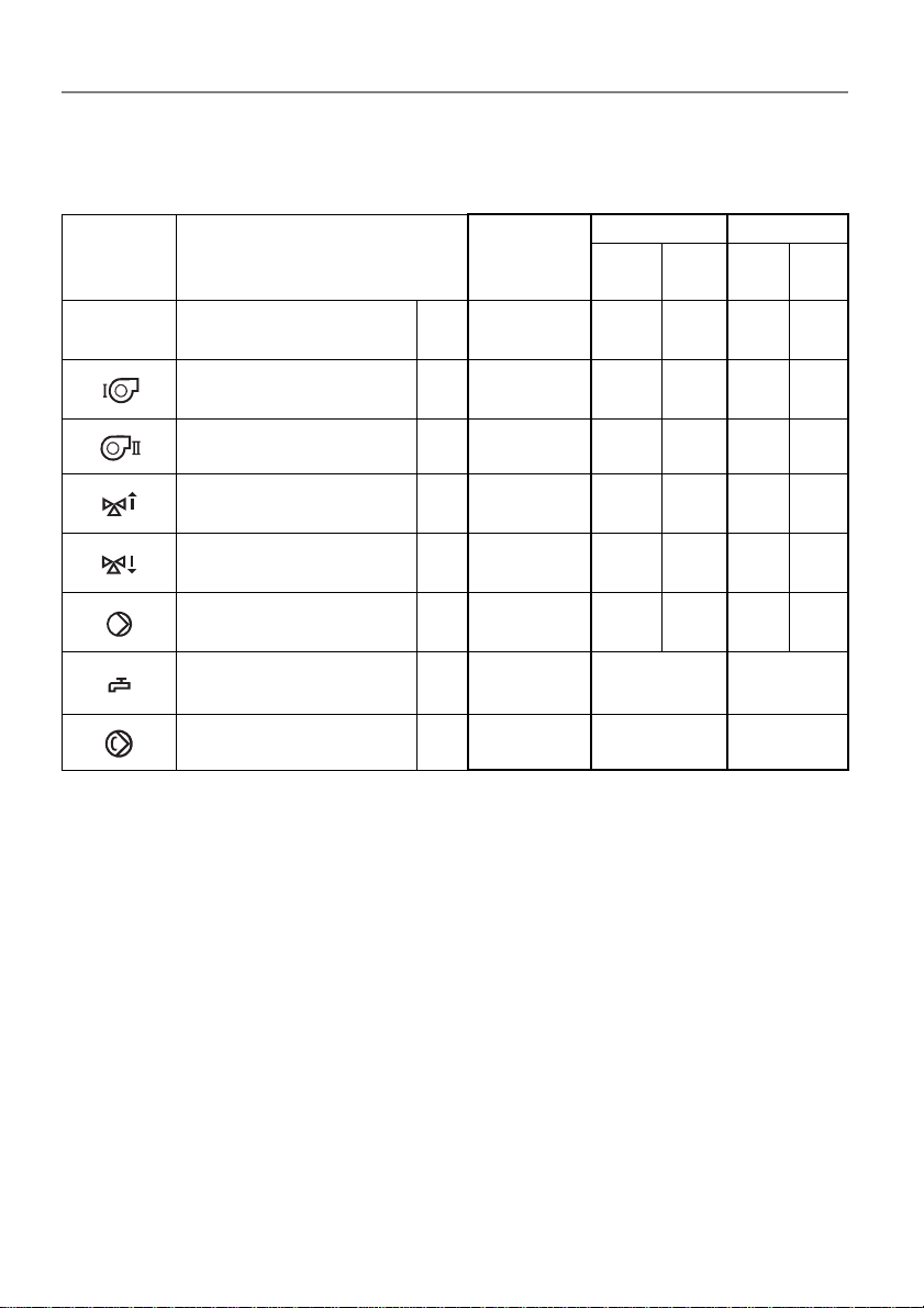
4.11 Displaying the controller output ports
Depending on the state of the unit and the operating mode, some of these symbols
will be shown.
DHR - classic DHR - comfort DHR - expert
1
green2red1green2red
FA
b1
X X X X X
X X X
Symbol
Designation
heating circuit/generator
(1=green; 2=red)
Modulation heat generator
Generator I or
burner stage I
Burner stage II b2
Heating circuit mixing
valve open
Heating circuit mixing
valve closed
Heating circuit circula-
tion pump
Charging pump/deflec-
tor valve
M+
M-
U
L
Circulation pump DHW C
X X X
X X X X
X X X X
X X X X X
X X X
X
20
Dok. Nr. 112648 33/2010
Page 21
Operating manual
B
D
C
turn quickly
DHR - classic DHR - comfort DHR - expert
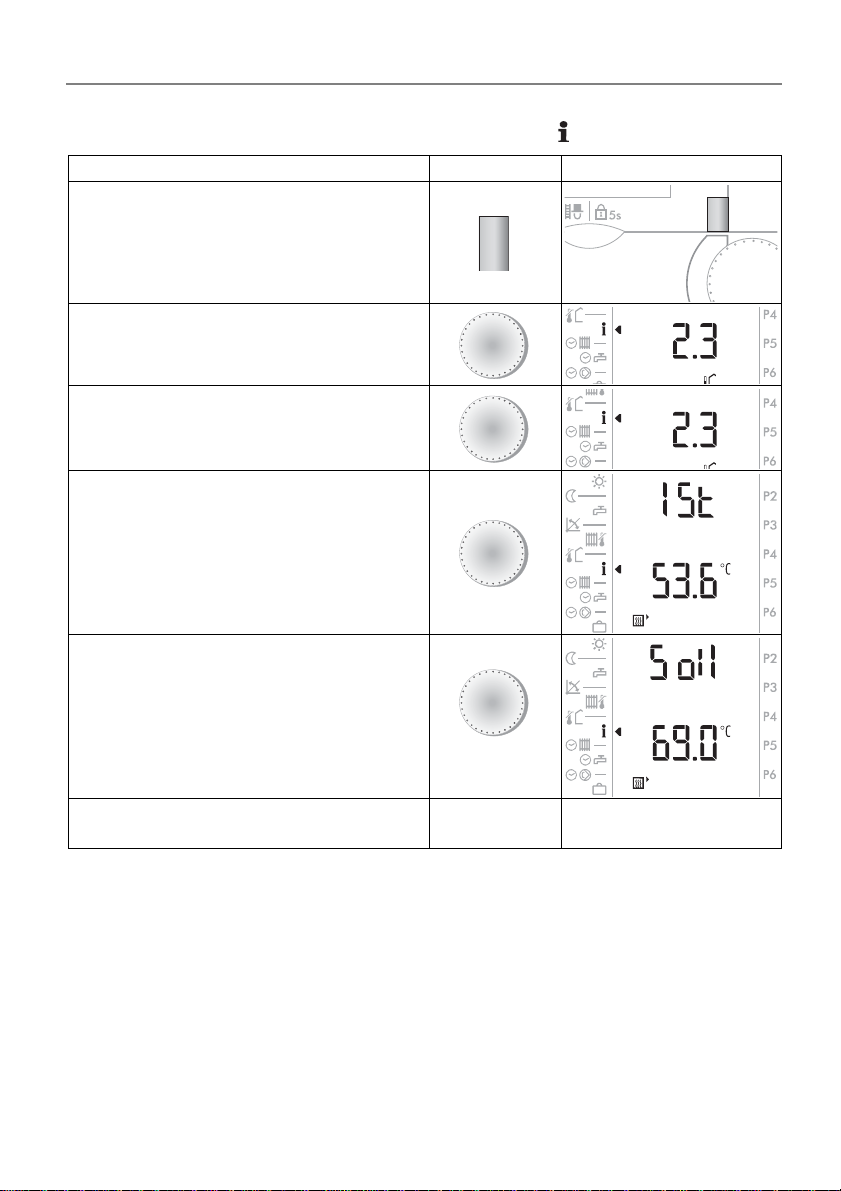
4.12 Displaying temperatures and values
Operation step Operation Display
Select the heating circuit or generator
(in case of setting on 7-0)
Select function
Displaying of temperatures and values
Example: outside temperature 2.3 °C
Displaying actual value
Displaying set and actual values
D
A
B
B
B
Select another function
or close the cover
The standard display
appears
Dok. Nr. 112648 33/2010 21
Page 22
Operating manual
DHR - classic DHR - comfort DHR - expert
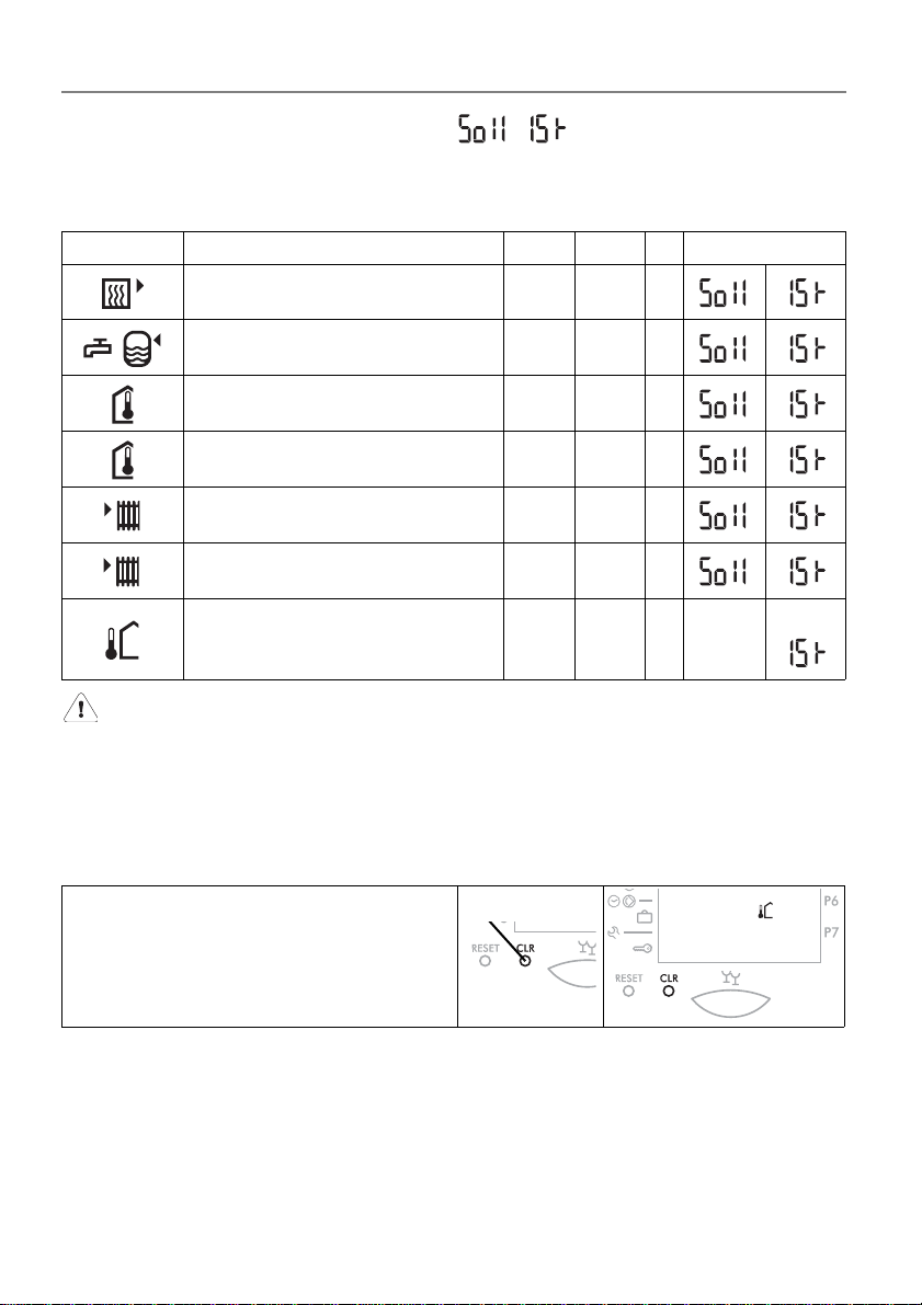
4.12.1 Set values and actual values
Actual value = measured value
Set value = control value (by turning the setting knob B quickly)
Displaying the actual temperatures serves to check the sensors.
Symbol Designation Key Abbr. Display
Boiler flow temperature WEZ 1 green TK 1 °C
Domestic hot water temperature TB °C
Room temperature 1 green TI 1 °C
Room temperature 2 red TI 2 °C
Heating circuit supply flow tem-
perature 1
Heating circuit supply flow tem-
perature 2
Averaged outside temperature
Actual outside temperature
If the sensor configurations were saved at start-up, defe ctive sensors will be shown to register 120 °C. Exception: TA = 0 °C.
green TV 1 °C
red TV 2 °C
°C
TA
TA
°C
4.13 Transfer the value to the standard display (1st level)
1. Select the desired value as explained before.
2. Press CLR key with a thin object.
Press CLR key with a thin object
3. Close the cover. The desired value is now shown in the standard display.
22
Dok. Nr. 112648 33/2010
Page 23
Operating manual
DHR - classic DHR - comfort DHR - expert
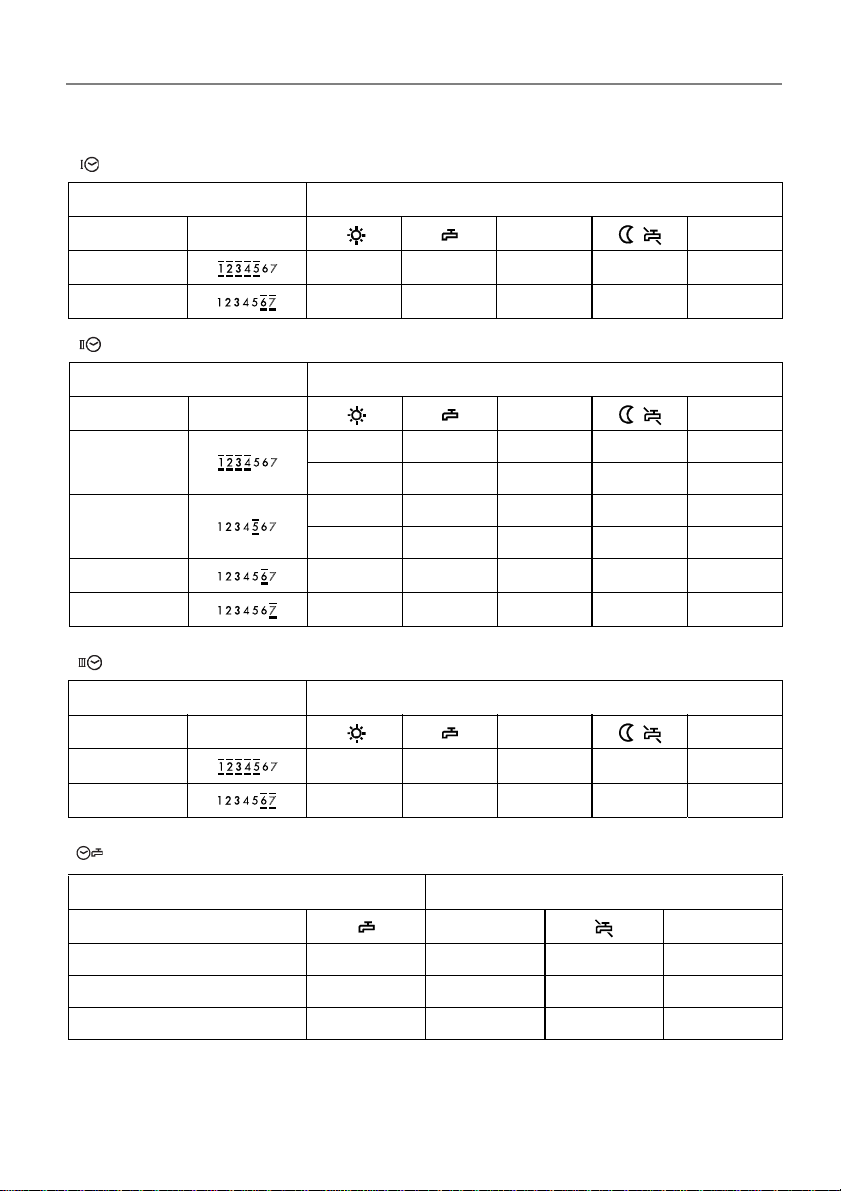
4.14 The standard clock programs (factory settings)
P1 = Clock program 1, standard domestic program
Blocks of days Heating and (domestic hot water)
Weekday Marked days
( )
Mo-Fr 06.00 (05.00) 22.00
Sa-So 07.00 (06.00) 23.00
P2 = Clock program 2, heating with reduced periods on working days
Blocks of days Heating and (domestic hot water)
Weekday Marked days
Mo-Do
Fr
06.00 (05.00) 08.00
15.30 (14.30) 22.00
06.00 (05.00) 08.00
( )
15.30 (14.30) 23.00
Sa 07.00 (06.00) 23.00
So 07.00 (06.00) 22.00
Note
Note
Note
Note
P3 = Clock program 3, offices and industrial premises
Blocks of days Heating and (domestic hot water)
Weekday Marked days
( )
Note
Note
Mo-Fr 06.00 (05.00) 19.00
Sa-So - - continu.
P1 = Separate clock program of domestic hot water
Blocks of days Domestic hot water
Weekday
Note Note
Mo-So 00.00 00.00
Note
Note
Note: There is no individual DHW program preset at the factory.
Dok. Nr. 112648 33/2010 23
Page 24
Operating manual
DHR - classic DHR - comfort DHR - expert
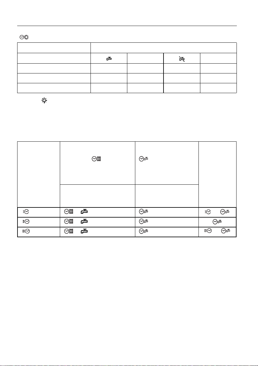
P1 = Clock program of circulation
Blocks of days Circulation pump
Weekday
Note Note
Mo-So 06.00 08.00
Mo-So 11.30 13.30
Mo-So 17.00 21.00
Note: = start clock program (start of heating in according with setting 3-6).
The clock program of domestic hot water starts ever 1 hour first of the heating program.
4.14.1 Cooperation of the standard and the individual D.H.W. clock program (Example)
Operating
mode
1st Level
Standard clock program
domestic hot water
P1/P2/P3
factory setting = on
on = active
off = inactive
see "4.16.1, page 28
P1 on/off P1
Individual D.H.W.
clock program P1
There is no individual
DHW program preset at
the factory
always active
see chapter "4.16.2,
page 29
active clock
program
+
P2 on/off P1
P3 on/off P1
+
With position "off" only the individual domestic hot water clock program P1 is active. With position "on", the two clock programs (standard/individual) overlay, i.e.
both clock programs are active at the same time.
24
Dok. Nr. 112648 33/2010
Page 25
Operating manual
DHR - classic DHR - comfort DHR - expert
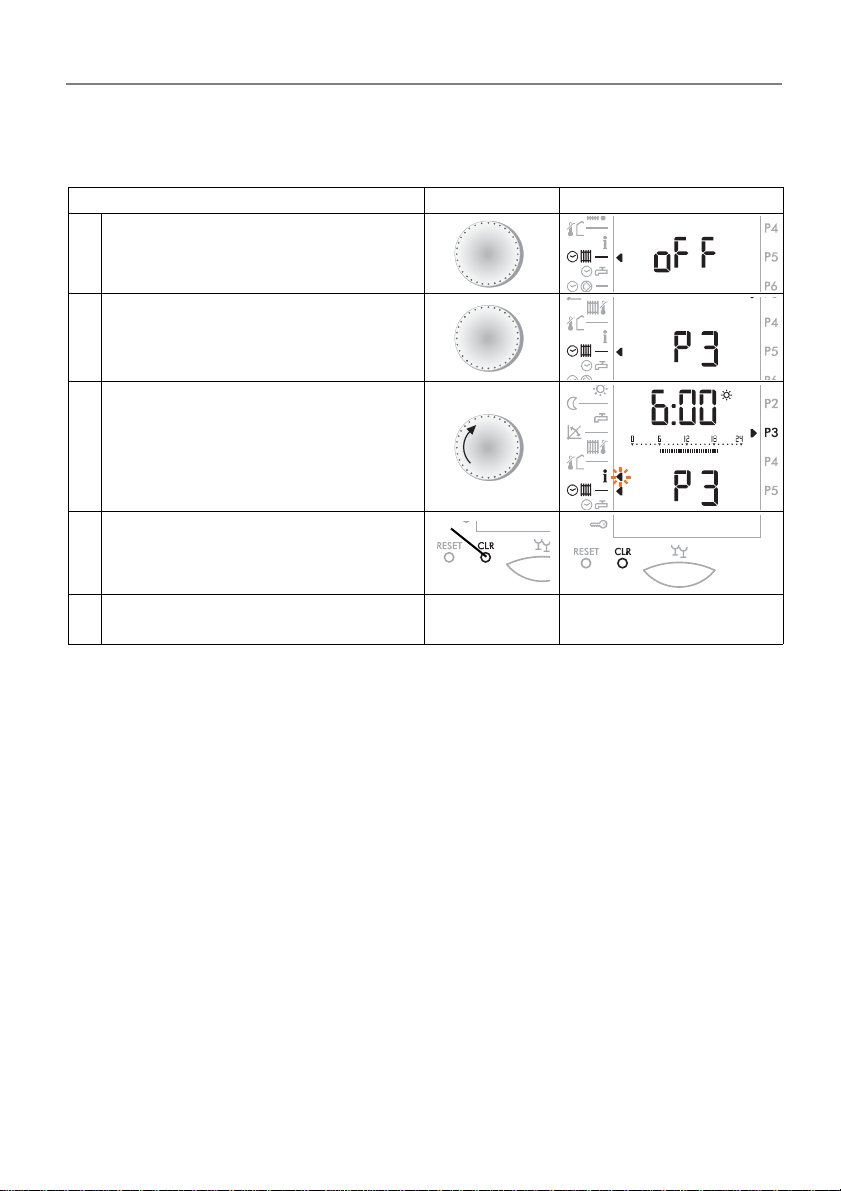
4.14.2 Reload of standard clock programs preset at the factory
The standard clock programs preset at the factory can be relo aded at any time,
see
"4.14 The standard clock programs (factory settings)", on page 23.
Operation step Operation Display
Open cover
1
Select function
Select program P1 until P3
2
Example: Program P3
Display clock program
3
Example: Program P3
4 Press CLR key with a thin object
A
B
A
Close cover, the standard clock
5
program is reloaded
Dok. Nr. 112648 33/2010 25
Close cover
The standard display
appears
Page 26
Operating manual
D
B
D
C
B
D
C
DHR - classic DHR - comfort DHR - expert
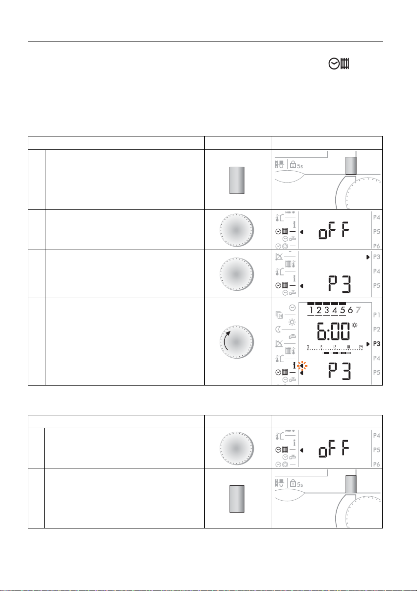
4.15 Setting the clock programs for heating/D.H.W.
A clock program defines the periods during which the room temperature o r domestic hot-water temperature (DHW temperature charging starts one hour earlier)
should correspond to the set temperature.
4.15.1 Checking the clock program for heating/D.H.W. mode
Operation step Operation Display
Select heating circuit
1
(in case of setting on 7-0)
Open cover
2
Select function
Select program P1 until P3
3
Example: Program P3
A
B
Display clock program
4
Example: Program P3
4.15.2 Changing the clock program for heating/D.H.W mode
Operation step Operation Display
Open cover
1
Select function
2 Select heating circuit
26
A
A
D
Dok. Nr. 112648 33/2010
Page 27
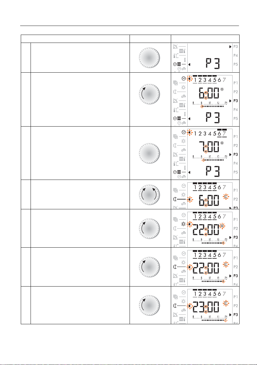
Operating manual
2 x
DHR - classic DHR - comfort DHR - expert
Operation step Operation Display
Select program P1 until P3
3
Example: Program P3
B
Activate changes
4
Example: Program P3
Select block (or day of the week)
and time for which the setting app
5
lies ("starting point").
Fast rotation accelerates setting.
Change between night reduction
6
heating and heating mode
Set the heating period
7
The black segments will be added
Select set night reduction heating
8
period
A
-
B
A
B
A
Set the night reduction heating
period Black segments, if any are
9
marked, will be deleted.
Dok. Nr. 112648 33/2010 27
B
Page 28
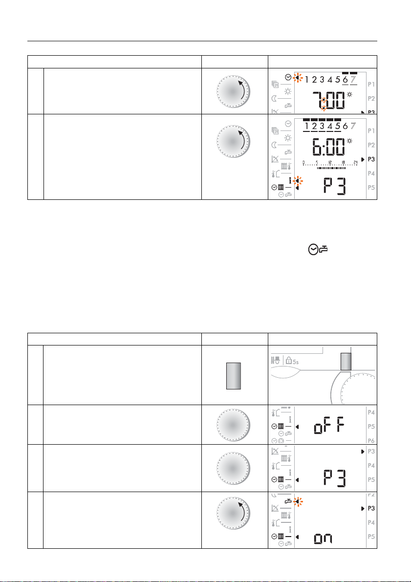
Operating manual
or
close cover
B
D
C
A
1 x
DHR - classic DHR - comfort DHR - expert
Operation step Operation Display
Select new day/period for further
changes.
10
Repeat steps as given above.
Leave function
The finished clock program is now
saved.
11
The program can now be checked
again, or will be saved when the
cover is closed.
The standard display appears.
Note: The shortest period to be set for heating mode is 30 minutes.
A
A
4.16 Setting an individual D.H.W. clock program P1
Note: Only the clock program P1exists.
4.16.1 Separating the clock program D.H.W. from the standard clock program heating
To program and activate an individual D.H.W. clock program, it must be se parated
from the standard clock program for heating.
Operation step Operation Display
Select heating circuit
1
(in case of setting on 7-0)
Open cover
2
Select function
Select program P1 until P3
3
Example: Program P3
Select function:
Factory setting P1 - P3 is "on"
4
on = D.H.W. according to "Setting the
28
clock programs for heating/
D.H.W."; page 26
D
A
B
Dok. Nr. 112648 33/2010
Page 29
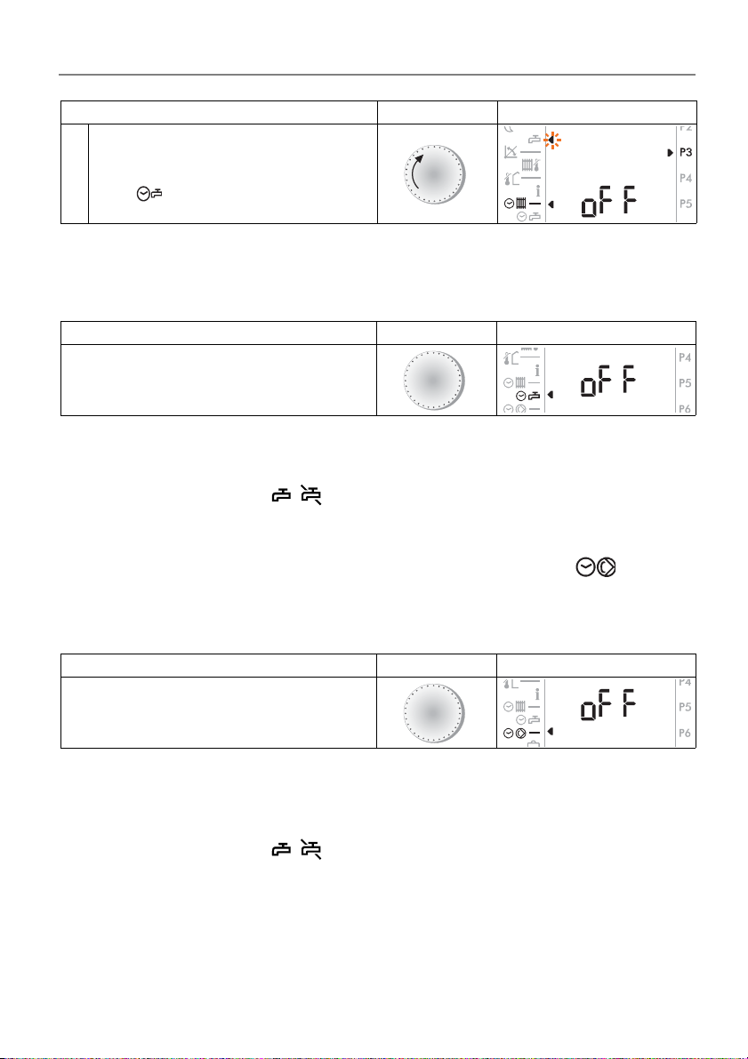
Operating manual
DHR - classic DHR - comfort DHR - expert
Operation step Operation Display
off = D.H.W "AUS" or
5
Note: If the individual D.H.W. clock program is not separate d, it overlaps with
4.16.2 Display an d ch an ge th e individual D.H.W. clock program Operation step Operation Display
individual D.H.W. clock program
is active
the standard clock program of heating and both are active.
B
Select function
Further control steps:
"4.15.1 Checking the clock program for heating/D.H.W. mode", on page 26, and
"4.15.2 Changing the clock program for heating/D.H.W mode", on page 26.
The symbols in the display apply to change between an active and inactive
domestic hot water charge.
A
4.17 Setting the circulation pump clock program P1
Note: Only the clock program P1exists.
4.17.1 Display and change the circulation pump clock program Operation step Operation Display
Open cover
Select function
Further control steps:
"4.15.1 Checking the clock program for heating/D.H.W. mode", on page 26, and
"4.15.2 Changing the clock program for heating/D.H.W mode", on page 26.
The symbols in the display apply to change between an active and inactive
circulation pump.
A
Dok. Nr. 112648 33/2010 29
Page 30
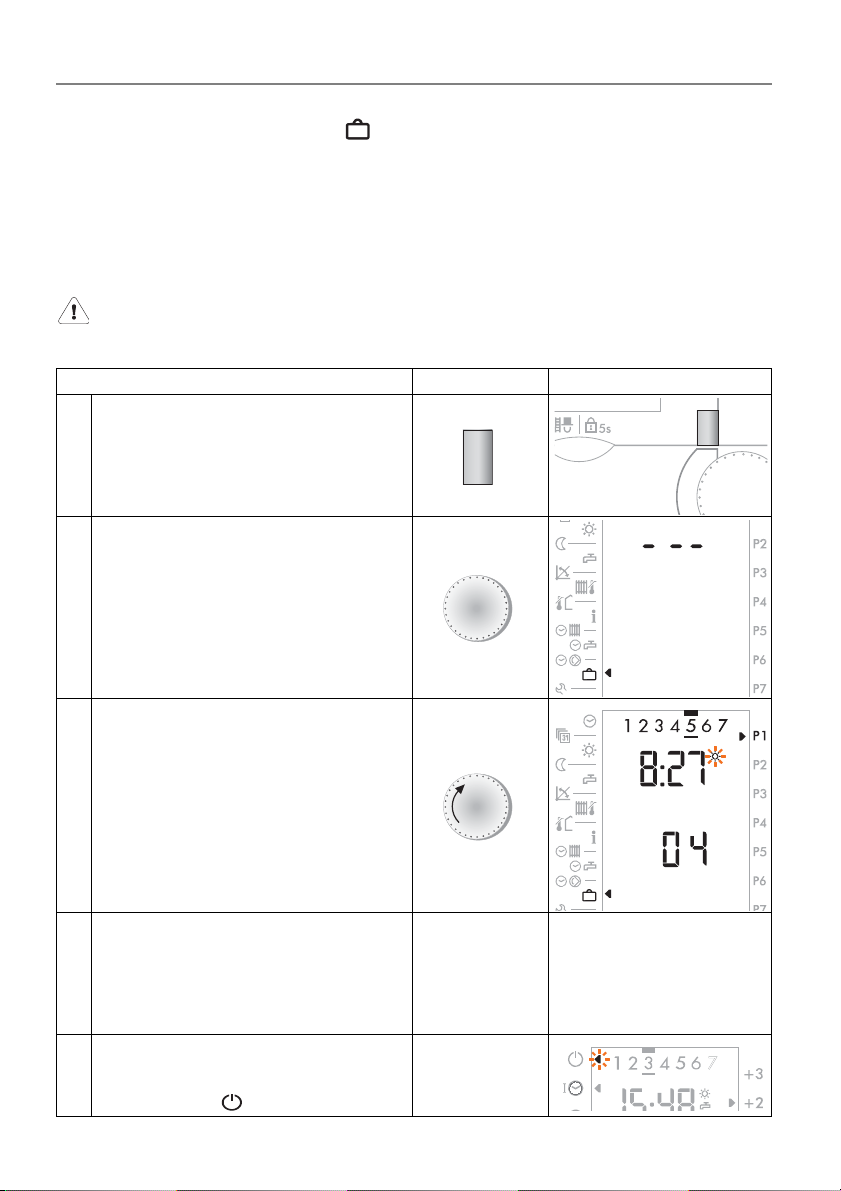
Operating manual
B
D
C
B
DHR - classic DHR - comfort DHR - expert
4.18 Vacation program
With the vacation program only room protection heating is active (adjuster 3-0),
the domestic hot water is switched off. For programming, only the date for the va
cation program’s end must be set. The vacation program begins at 24:00 o'clock
on the day of its setting. The vacation program ends at the change of date (mid
night 12:00 p.m.).
Pressing the "Party Key" cancels an active vacation program.
4.18.1 Setting the vacation program Operation step Operation Display
Select heating circuit
1
(in case of setting on 7-0)
D
-
-
2 Select function
3 Set the date of end of vacation.
Leave function
The finished vacation program is
now saved.
4
The vacation program becomes
active starting from 24:00 o'clock.
As soon as the vacation program is
active, a cursor flashes in the case
5
of the symbol
30
A
Close cover
Standard display
appears
Dok. Nr. 112648 33/2010
Page 31
Operating manual
D
B
D
C
DHR - classic DHR - comfort DHR - expert
4.18.2 Vacation pro g ram di spla y /ch a n ge /t ermi na t e Operation step Operation Display
Select heating circuit
1
(in case of setting on 7-0)
display:
Select function
2
The end of the vacation program
appears
change:
3
Change the date of vacation end
A
B
terminate:
Turn with adjusting knob B to the
left side until appears "---"
4
The vacation program is deleted
or...
...the vacation program can also be
5
deleted with the Party key.
6 Leave the function Close cover
B
C
The standard display
appears
Dok. Nr. 112648 33/2010 31
Page 32
Operating manual
D
C
1 x
DHR - classic DHR - comfort DHR - expert
5 Service level
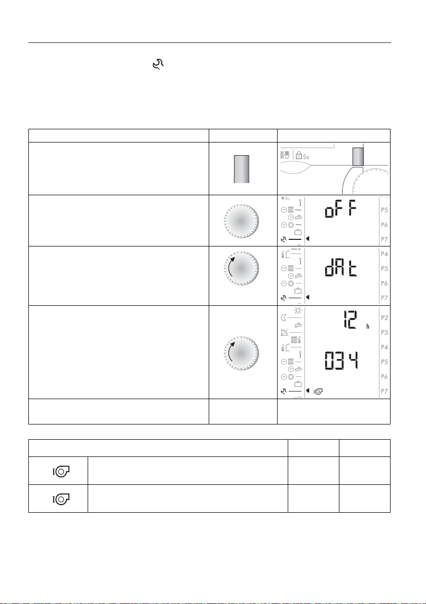
5.1 Query operating data
The operation hours and switching cycles of the burner stages as well as further
data can be queried.
Operation step Operation Display
Select generator
(in case of setting on 9-0)
Select service level
Select function "dat"
Query data
Example: Operation hours of the bur-
ner stage I = 12’034 hours
Leave the function Close cover
Operating data Key D Unit
D
A
B
A
The standard display
appears
32
Operating hours burner stage I green h
Switching cycles burner stage I green
Dok. Nr. 112648 33/2010
Page 33
Operating manual
D
C
2 x
DHR - classic DHR - comfort DHR - expert
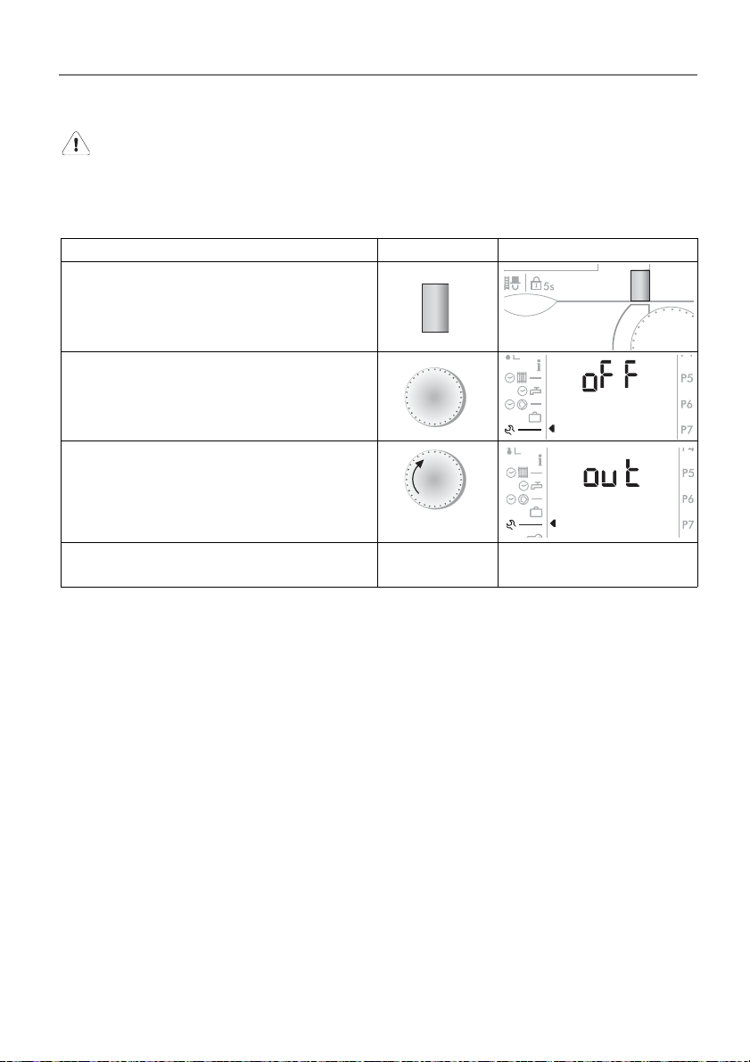
5.2 Switching output functions on and off
This function is reserved for technicians only!
This function serves for testing output functions. Each output function may be selected and switched on or off. The system can be tested to check whether the switched-on output function is correctly executed.
Operation step Operation Display
Select heating circuit
(in case of setting on 7-0)
Select service level
This function is reserved for technicians only!
Select another function
or close the cover
D
A
B
The standard display
appears
Dok. Nr. 112648 33/2010 33
Page 34
Operating manual
B
D
C
B
1 x
DHR - classic DHR - comfort DHR - expert
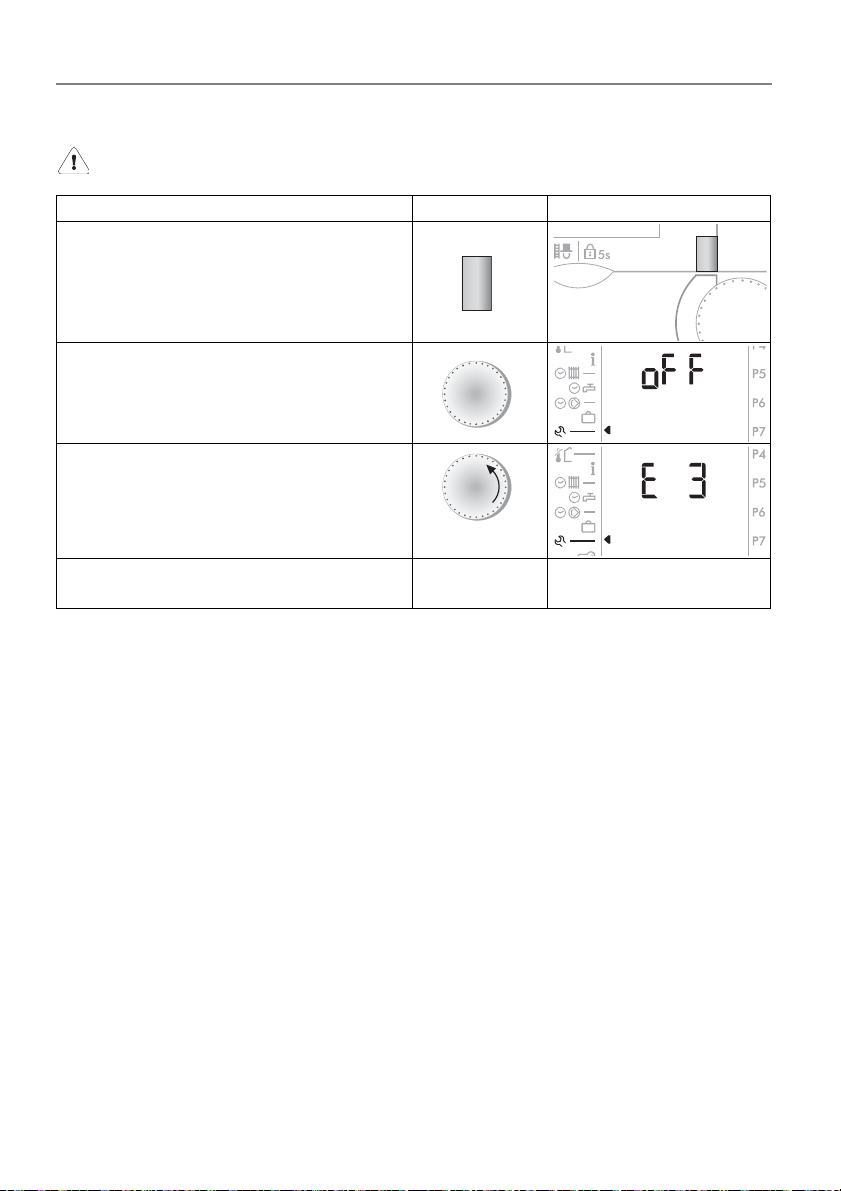
5.3 3. Level
This function is reserved for technicians only!
Operation step Operation Display
Select heating circuit
(in case of setting on 7-0)
Select service level
This function is reserved for technicians only!
Select another function
or close the cover
D
A
The standard display
appears
34
Dok. Nr. 112648 33/2010
Page 35
Operating manual
DHR - classic DHR - comfort DHR - expert
5.4 Error message
5.4.1 General informat io n
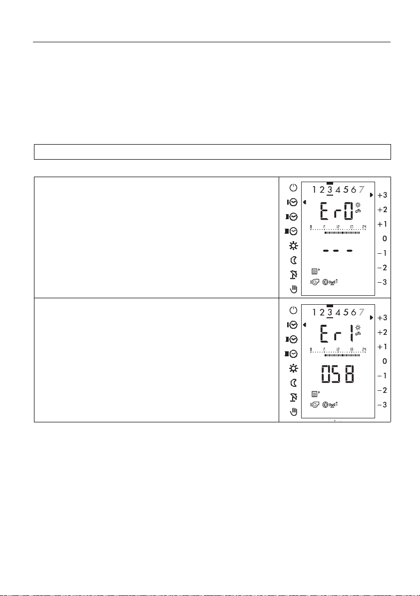
In case of an error the backlight of the display switches on
sed) in place of the time the display appears "Er 1... 8", in place
temperature - an error-number "00 to 99" or "-".
. On level 1 (cover clo-
of the selected
The display Er 1... 8 describes the cascade level in
Er 1 =
eBUS-error
Short-circuit in the eBUS wiring
Disturbance of an external firing automat over eBUS
The error code in the lower dis
dependent. The meaning is to be inferred from the
operating instructions of the firing automat.
Generator
play-line is product
which the boiler is incorrect:
Dok. Nr. 112648 33/2010 35
Page 36
Operating manual
DHR - classic DHR - comfort DHR - expert
6 Definitions
Start of occupation The start of the occupation period, as programmed on the
timer.
Occupation period The period of time for which the system is heated to normal
temperature.
Technician levels These setting levels are reserved for technicians. They contain
setting parameters for adaptation of the controller to the heating system.
Heating-curve adaptation
Actual value The measured temperature.
Optimisation Automatic advancing of the time at which heating is to begin, in
Setpoint Temperature, defined by user or technician, to which the heating
Automatic adaptation of the heating curve for the building.
accordance with the heating requirement.
controller regulates the actual temperature.
36
Dok. Nr. 112648 33/2010
Page 37

Operating manual
DHR - classic DHR - comfort DHR - expert
7Index
A
Adjusting room temperature heating
operations ................................11
Adjusting the heating curve ..........18
C
Changing the clock program for hea-
ting/D.H.W mode .....................26
Checking the clock program for hea-
ting/D.H.W. mode .... .... ... ... ... ...26
Cooperation of the standard and the
individual D.H.W. clock
program ................................... 24
D
Display and change the individual
D.H.W. clock programm ..........29
Displaying temperatures and
values ...................................... 21
Displaying the controller output
ports ........................................20
E
Error message ..............................35
L
Locking ................................... ...... 11
M
Measuring of emissions (chimney
sweep service) ........................12
O
Overview of displays ......................4
Q
Query operating data ...................32
S
Safety instructions ......................... 7
Selecting an operating mode ....... 10
Set values and actual values ....... 22
Setting the automatic programs for
heating/D.H.W. ....................... . 26
Setting the circulation pump clock
program ................................... 29
Setting the date ............................ 16
Setting the heating limit (summer/win-
ter) ....................................... .... 19
Setting the maximum supply tempe-
rature ...................................... . 19
Setting the room temperature for
night reduction heating mode .. 17
Setting the room temperature heating
mode ...................................... . 16
Setting the time (clock) ................ 15
Setting the vacation program ....... 30
Setting the warm water
temperature ............................. 17
Switching on the party function .... 15
Switching output functions on
and off ....... ... .... ... ... ... .... .......... 33
T
Transfer the value to the standard
display (1st level) .................... 22
U
Unlock during error message (TEM fi-
ring automatic) ................. ... ... . 14
V
Vacation program ........................ 30
Vacation program display/change/
terminate ................................. 31
R
Reload of standard clock programs
preset at the factory .................25
Dok. Nr. 112648 33/2010 37
Page 38

Manufacture or distribution:
OEG GmbH
Industriestrasse 1
D - 31840 Hess. Oldendorf
Fon: 00800/63436624
Fax: 00800/63432924
http://www.oeg.net
e-mail: [email protected]
 Loading...