


 Loading...
MINI6600TM Mobile Digital C-Arm Service Manual - Periodic Maintenance
MINI6600TM
Digital Mobile C-Arm
Periodic Maintenance Procedure
00-879519-01
© December 1997
OEC Medical Systems, Inc.
384 Wright Brothers Drive
Salt Lake City, Utah 84116

MINI6600TM Mobile Digital C-Arm Service Manual - Periodic Maintenance
This manual may not be reproduced, in whole or in part, without the written permission of
OEC Medical Systems, Inc.
This procedure does not contain any steps which can be performed by the system operator. The steps contained in this procedure should not be attempted by anyone
who is not specifically trained or authorized by OEC to work on the
MINI6600TM system.
The contents of this procedure are accurate at the time of publication. However, changes in design and additional features may be incorporated in the hardware and software which are not reflected in this version of the procedure. Contact OEC Technical Support for clarification, if discrepancies arise.
|
|
|
The MINI6600 Digital Mobile C-Arm is |
|
|
|
manufactured under the following U.S. Patents: |
|
|
|
4.768.216; |
|
|
|
4.797.907; |
|
|
|
4.209.706. |
|
|
|
Other Patents Pending. |
Revision History |
|
|
|
Rev |
Dash |
Date |
Change Description |
1 |
-01 |
Jul 96 |
Initial Publication |
A |
-01 |
Aug 96 |
Manufacturing Release |
|
|
Dec. 97 |
CD-ROM Release |
|
|
|
|
|
|
|
|

MINI6600TM Mobile Digital C-Arm Service Manual - Periodic Maintenance
General Instructions
Use the following procedures to perform periodic maintenance on the MINI6600 Mobile Imaging System. The MINI6600 Periodic Maintenance Form must be completed as the procedures in this manual are performed. If the system does not pass a portion of the procedure, correct the problem before completing the PM Form. Note all failures and the corrective action taken in the comments section of the PM Form. Additional space is provided at the end of the PM Form.
The tools and test equipment that are required to perform Periodic Maintenance, are described inAppendix A.
All Torx screws have recommended torque specifications. These specifications are described in AppendixA.
IMPORTANT:
The PM Procedures do NOT list all the steps necessary to complete the PM.
The service engineer WILL NEED the Service Manual (00-878315) to complete the PM.

MINI6600TM Mobile Digital C-Arm Service Manual - Periodic Maintenance
SAFETY
Ingress Of Water And Solutions
The system must never be operated or stored in locations where conductive fluids, like water and saline solution, might spill on the equipment.
Always unplug the AC power cable from the wall outlet before cleaning the equipment. Do not allow water, soap, or other liquids to drip into the equipment and cause short circuits, electric shock and fire hazards.
Mechanical Operation
The Articulating arm is manually adjusted.
Trained Service Personnel
Serious injury and property damage can result from incorrectly performed service procedures. Observe all operating and safety procedures contained within this manual.
WARNING:
Procedures contained in this manual should only be performed by service personnel specifically trained by OEC Medical Systems, Inc. to calibrate the MINI6600 System.

MINI6600TM Mobile Digital C-Arm Service Manual - Periodic Maintenance
Electrical Shock
WARNING:
This system is capable of generating lethal voltages. Observe safe electrical testing procedures when performing periodic maintenance procedures on the system.
X-Radiation Exposure
The X-ray tube assembly produces X-radiation when energized. Never operate this device without X-ray shielding in place. Use lead shielding and draping to protect personnel.
WARNING:
Lead aprons, radiation monitors and appropriate radiation shields must be utilized by personnel while performing tests.
Living human anatomy should never be used as a phantom or demonstration aid.
CAUTION:
Many of the PCB’s in this system contain components which are sensitive to Electro-Static Discharge (ESD). Observe ESD safety procedures.

MINI6600TM Mobile Digital C-Arm Service Manual - Periodic Maintenance
WARNING: Labels
The following warning labels may be found on the system:
X-RAY SAFETY WARNING:
WARNING: Symbols
The following symbols may be found on the MINI6600:
DANGEROUS VOLTAGE PRESENT
Dangerous voltages are present use safety precautions.
DANGEROUS VOLTAGE PRESENT
Dangerous voltages are present - use safety precautions.
MINI6600TM Mobile Digital C-Arm Service Manual - Periodic Maintenance
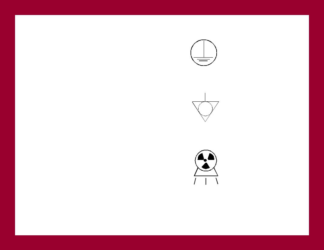
EARTH GROUND
The protective earth ground should be the last electrical connection broken and the first electrical connection made during servicing procedures.
POTENTIAL EQUALIZATION
GRN/YEL wire is used to indicate protective earth conductors, accessible parts connected to earth parts, and potential equalization conductors.
EMITTING X-RAY SOURCE
This symbol indicates the presence or potential of producing ionizing X-radiation.

MINI6600TM Mobile Digital C-Arm Service Manual - Periodic Maintenance
NON-A/P
This symbol indicates that equipment is non-anesthetic proof and should not be operated in the presence of flammable vapors, liquids or other substances.
ATTENTION |
! |
|
This symbol cautions you to refer to the service manual for additional information.

MINI6600TM Mobile Digital C-Arm Service Manual - Periodic Maintenance
Completing the PM Form
1.At the top of the MINI6600 Periodic Maintenance Form, check whether you are performing a SemiAnnual or an Annual PM.
2.Completely fill in the customer information block, including the Time Of Day (start time) measured in military time, System Serial Number and the Field Service Report (FSR) / Request ID Number. Indicate the system configuration with appropriate check marks.
NOTE:
Test equipment used must have current calibration dates. Do not use test equipment with expired calibration stickers.
3.While performing the Periodic Maintenance procedures, log all test equipment used in the Test Equipment Used block of the Periodic Maintenance Form.
4.Place a check mark on the PM Form as each test paragraph is completed. Fill in actual measured values where indicated on the PM Form. If adjustments are made, note the adjustment in the comments section of the PM Form.

MINI6600TM Mobile Digital C-Arm Service Manual - Periodic Maintenance
Begin Periodic Maintenance
Remove the Power And Covers
WARNING:
Electrical circuits inside the equipment use voltages that are capable of causing serious injury or death from electrical shock. Use appropriate precautions.
1.If the system has power applied, position the System keyswitch/pushbutton to the OFF position. Verify that the System’s AC power cord is not plugged into the wall outlet.
2.Remove the System covers. Refer to the System Overview section in the MINI6600 Digital Mobile C- Arm Service Manual (00-878315) for cover removal procedures.
Elapsed Time Indicator
Read the elapsed time meter on the System and enter the number on the PM Form.
Inspect the Static Drag Wire
1.Verify that the static drag wire underneath the System is touching the floor.
2.Verify the static drag wire is securely attached.
Inspect the Articulating Arm and Brake
Verify that the articulating arm mechanics move freely and smoothly throughout the entire range of motion.
MINI6600TM Mobile Digital C-Arm Service Manual - Periodic Maintenance
Inspect the Rotation Brake
1.Release the rotation brake and rotate the MINI-C assembly.
2.Verify smooth rotation.
3.Verify that the brake locks the mechanics in any position within the range of motion.
Inspect the Orbital Brake
1.Release the orbital brake.
2.Move the MINI-C throughout the orbital range. Ensure smooth operation.
3.Verify that the brake locks the mechanics in any position within the range of motion.
Verify the System Steering And Brake Operations
1.Select the LOCK mode by pressing the steering brake pedal completely down. Verify that the casters and wheels are locked in position and do not move.
2.Select the FREE mode by lifting the steering pedal up halfway. Verify that the casters rotate and the wheels roll freely.
3.Select the STEER steering mode by lifting the steering pedal completely up. Verify that the casters rotate into the steering position and lock, and the wheels roll freely.
Loading...