

Page 1
Installation Instructions
Please read these instructions thoroughly before installing your Solar Flair™ Tubular Skylight.
Pay particular attention to the assembly diagrams, assembly order, and part names.
(not all items shown are to scale)
FOR INSTALLATION ON AN ASPHALT ROOF
For cathedral ceiling (12” or less) & long shaft installations (6’or more) see Page 7.
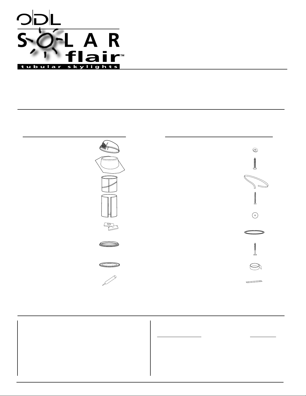
Qty Part Description
(1) Solar Lens™ Dome
(1) Roof flashing
(2) Adjustable tubes
(1) Extension tube (20”)
(4) Ceiling anchors
(1) Ceiling trim ring with
screw caps
(1) Flat ceiling diffuser
(1) Tube of roof sealant
Qty Part Description
(4) Dome washers
(4) Dome screws – 3/4"
(1) Dome gasket – black
(8) Flashing screws – 2"
(6) Flashing washers
(1) Tube ring seal – white
(4) Drywall screws (black)
(1) Roll of foil tape
(1) Hole cutting template
optional components:
SOLD SEPARATELY ODL ITEM#
Extension tube (20”) as shown above EZ14T20
Extension tube (48”) EZ14T48
Prismatic ceiling diffuser EZ14CD
White ceiling diffuser EZ14WD
Electric light kit EZELK
Safety Glasses
Work Gloves
Pencil
Tape Measure
Plumb Line
Utility Knife
Phillips Screwdriver
Tin Snips
Caulking Gun
Claw Hammer
Flat Pry Bar
Power Drill
Reciprocating/Sabre Saw
Keyhole/Drywall Saw
tools required:
standard kit parts list: hardware pack items:
14" Tubular Skylight
Page 2
REVIEW THIS INFORMATION PRIOR TO BEGINNING INSTALLATION
caution:
• The tubular skylight is not designed to hold your
weight or the weight of tools or other objects.
Walking/placing objects on the skylight could
cause personal injury and property damage.
A damaged skylight should be repaired
immediately.
• For safe installation and use, do not deviate
from these installation instructions.
warning:
Working on a roof is potentially dangerous but
you can significantly reduce the risk by following
these precautions:
• Never work in wet, windy or cold conditions.
Roofing materials can be slippery when wet;
asphalt shingles are brittle when cold and may
crumble underfoot. Plan your installation for
a pleasant, calm, dry day.
• Wear shoes with slip-resistant soles.
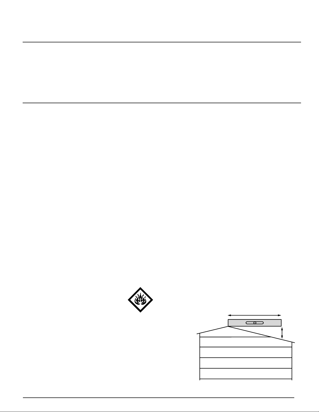
POTENTIAL FIRE HAZARD. After removing
film lining from interior of tube shaft, DO NOT
leave tube shaft components unattended
and exposed to direct sunlight.
Exposed surfaces may catch fire or
incur heat damage until tube shaft
is properly installed. Assembly and
installation of tube shaft and attachment of the
inner diffuser eliminates potential hazards from the
reflective inner surface.
safety information:
• Wear safety glasses and work gloves when
using power tools.
• Use protective work gloves while handling tube
sections to protect hands from sharp edges.
tips:
• Consult your local building official about local
construction ordinances before starting your
installation.
• Consult your community covenants.
Some subdivisions may not allow tubes on the
street side of the home.
• Before installation, carefully survey the attic area
of desired location, roof valleys, ceilings, and any
ceiling-mounted registers or fans.
• Make careful note of the location of wiring,
plumbing and mechanical attic equipment.
• For best results in colder climates, the tube
shaft should be insulated in the attic space.
• For best results always attempt to install the
tube as straight as possible.
• The molded (N) on the Solar Lens™ Dome
should face north for optimum performance.
determining roof pitch:
• “Roof Pitch” is how far the roof drops vertically
for every 12” of horizontal run.
• Asphalt roof applications require a minimum
pitch of 3:12 and a maximum of 12:12.
12
X
Solar Flair 14" Tubular Skylight
What you need to know
These instructions have been designed to help install your Solar Flair™ Tubular Skylight easily and safely. We’ve included
a parts list, list of tools required, installation instructions for a variety of ceiling types, handy tips, and safety precautions.
Please read these instructions thoroughly before installing your Solar Flair™ Tubular Skylight. Pay particular attention to
the assembly diagrams, assembly order, and part names. Identify and organize all parts before assembly. Make a list of
the tools and components you will need for each installation location. Following these instructions carefully will greatly
enhance your ability to install your tubular skylight and enjoy flawless performance for many years.
2
pitch = X⁄12
Page 3
A
B
tip: Cut and insert a section of
a coat hanger wire through
the hole. This will more
easily identify the hole
location in the attic.
tip: To bring in the most light
available, always try to
position dome/flashing
so it views direct sun
throughout the day
without obstruction,
from trees, buildings, etc.
C
D
Solar Flair 14" Tubular Skylight
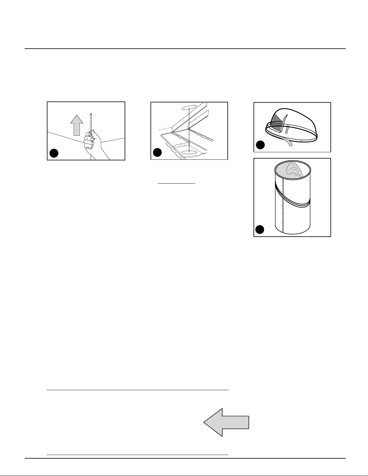
1
• Determine the desired
position of the tube
skylight on the ceiling.
• Using a stud finder or
hammer, find a location
between the ceiling joists.
• Push a screwdriver
through the desired
position. (Diagram A)
INSIDE
THE
ROOM
2
IN THE
ATTIC
3
PREPARE
THE
COMPONENTS
• Locate the wire and
adjust location to clear
any framing members by
at least 7 1/4” (204 mm).
Place wire through new
center point so that it
will be visible from above
after hole is cut in the
roof, and as center point
on face of ceiling below.
• Using a plumb line, find
a straight location from
the ceiling hole to the
roof location. Again,
clear any framing
members by at least
7 1/4” (204 mm).
(Diagram B) Work to
avoid valleys, wires,
pipes, ducts, etc.
• Drive a nail up through
the roof deck and shingles
at the roof location.
Installation Instructions
Rooftop Components QTY.
Solar Lens™ Dome (1)
Dome Washer (4)
Dome Screws (4)
Roof Flashing (1)
Flashing Screws (8)
Flashing Washers (6)
Adjustable Tube (1)
Hole Cutting Template (1)
Tube of Roof Sealant (1)
Rooftop Tools
Safety Glasses
Pencil / Marker
Caulking Gun
Utility Knife
Flat Pry Bar
Reciprocating/Sabre Saw
Drill (w/ Bits)
Phillips Screwdriver
Hammer
components:
Peel backing paper from
dome gasket and apply
to inside bottom edge of
the solar lens dome
(Diagram C).
(Do not stretch gasket.
Insure it seals to the dome
securely, and make sure
there is no gap or overlap
where ends meet).
Remove protective film
from inside of all the tubes.
(Diagram D)
[CAUTION: After removing
protective film,
keep tube sections out
of direct sunlight as
they focus sunlight and
generate intense heat.]
GATHER COMPONENTS
AND TOOLS NEEDED
ON THE ROOFTOP
3
Page 4

H
E
F
G
tip: You may have to drill
a hole inside the traced
diameter of the hole to
insert saw blade.
important:
Solar Lens™
Dome should
see the sun
throughout the
day for optimum
performance.
• Locate the protruding
nail and using the holecutting template, trace
the diameter of the
outer hole. 16” Dia.
(Diagram E)
• Using a reciprocating/
sabre saw, cut the hole.
• Use a flat bar to break
seals on shingles and
claw hammer to pull nails
above hole.
• Apply a bead of roof
sealant around the
perimeter of the flashing.
(Diagram F) Slide the
top and sides of the
roof flashing under the
shingles (Diagram G).
Secure the flashing to
the roof with the 2”
flashing screws and
washers provided.
(6 screws with washers
are centered in prepunched star holes; last
2 screws installed into
remaining round holes.
• Slide adjustable tube
down through the flashing
and adjust so it points to
the wire in the ceiling.
(Diagram H) Using the
3/4"dome screws and
dome washers (dome
washers have rubber
backing), mount the
dome on the flashing
aligning the “N” (North
indicator molded into
outer edge of the dome)
towards the North.
tip: Dome screws should
be snug but do not
overtighten.
Solar Flair 14" Tubular Skylight
Installation Instructions
4
ON THE
ROOF
5
ON THE
ROOF
6
ON THE
ROOF
OUTER HOLE
4
tip: Use roof sealant to seal
screw heads on flashing
and shingles to flashing.
Page 5

J
M
L
K
tip: Drill a pilot hole inside
the traced diameter of the
hole to insert saw blade.
• Using hole cutting guide
and pencil, locate
protruding wire and
trace the diameter of
the ceiling inner hole.
14-1/2” Dia. (Diagram J)
• Use a keyhole/drywall
saw to cut the hole.
• Secure the ceiling trim
ring with the 4 black
drywall screws provided.
Screws are driven thru
drywall into 4 white
ceiling anchors.
• Remove screw caps
from ceiling trim ring and
insert into drywall screw
head to hide screws.
(Diagrams K & L)
components:
GATHER COMPONENTS
AND TOOLS NEEDED
IN THE ATTIC
Attic Components QTY
Adjustable tube (1)
Tube (1)
Roll of foil tape (1)
Tube ring seal (1)
TOOLS
Tape Measure
Tin Snips
Utility Knife
• Place tube ring seal
around adjustable tube
and roll into position at
flanged end. Gently push
tube into trim ring (tube
ring seal should sit tightly
between trim ring and
tube). (Diagram M)
important:
Please see
Cut Your Tube
chart on following page.
7
INSIDE
THE
ROOM
INNER HOLE
TRIM RING
SCREW CAP
CEILING/
DRYWALL
TRIM RING
TUBE
TUBE RING SEAL
ANCHOR
5
Solar Flair 14" Tubular Skylight
Installation Instructions
8
IN THE
ATTIC
N
CONNECTING TUBE
ASSEMBLY
Be sure to measure and
cut if necessary, befor
e
removing adhesive strip
and assembling connecting
tube. (Diagram N)
• After referring to “cut
your tube chart” on the
next page, use metal
shears to shorten the
extension tube, allowing
for a 1” overlap at
each end.
9
IN THE
ATTIC
ADHESIVE STRIP
Page 6

P
Q
Cut Your
Tube
• Measure distance from
the top of flashing to ceiling.
(Diagram O) to determine
proper trimming of tubes.
Refer to “Cut Your Tube
Chart” for cutting
recommendations.
• Slide wide end of
extension tube over the
outside of lower adjustable
tube. Slide the narrow end
of the extension tube up
into upper adjustable tube.
• Tape ALL seams securely
with foil tape to keep
dust, moisture, and insects
out of the tube.
(Diagram P)
• Install the flat ceiling
diffuser. Align the
diffuser with the three
tabs on the trim ring and
turn clockwise until snug
in place. (Diagram Q)
chart:
installation
complete
10
IN
THE
ATTIC
11
INSIDE
THE
ROOM
Solar Flair 14" Tubular Skylight
Installation Instructions
TUBE OVERLAP
DISTANCE FROM
TOP OF
FLASHING TO
FACE OF CEILING
(take longest
measurement)
Less Than
15”
Measure and
cut adjustable
tube.
(See short shaft
installation)
Less Than
30”
Cut both
adjustable
tubes to fit.
Assemble with
a band of
connecting
tube. Cut for
1” overlap at
each end.
< 48”
< 30”
< 15”
> 48”
Less Than
48”
Use 20”
connecting
tube
to assemble.
Cut for 1”
overlap at
each end.
Greater
Than 48”
Use a
combination
of extension
tubes for
shafts.
Cut for 1”
overlap at
each end.
Greater
Than 72”
See long
shaft
installation.
6
tip: When trimming extension
tubes,
ALWAYS MEASURE AND
START FROM THE WIDE
END WHERE TUBE
DIAMETER = 14”.
When extension tube is
sized correctly, remove
backing paper from
adhesive strip on edge
of extension tube.
Beginning at one end of
the extension tube, overlap the edges of the tube,
aligning the edge of the
tube along the crimp in
the other edge.
(Once contact is made
with adhesive strip, parts
cannot be repositioned.)
O
Page 7

Solar Flair 14" Tubular Skylight
Installation Instructions
For cathedral ceiling installation,
use steps listed below, referring to
those listed on previous pages for
specific details. Disregard step 2.
• Cut holes in roof and ceiling.
• Install flashing to roof deck.
• Install adjustable tube into flashing.
Adjust this tube until it
protrudes through the ceiling
equally on all sides.
• Mark tube flush at ceiling.
Remove and cut tube on the line.
• Install trim ring.
• Install white tube ring seal to
adjustable tube and slide into
flashing.
• Press adjustable tube into
trim ring.
• Install dome.
• Install diffuser
CATHEDRAL
CEILING
INSTALLATION
For long shaft installation, use steps listed below,
referring to those listed on previous pages for
specific details.
• Locate and install top adjustable tube, trim ring,
and lower adjustable tube.
• Frame 2 x 4 between joists. Span from roof to
ceiling with a length of 2 x 4 flat to outside
of
each adjustable tube as a spine.
• Put a #6 x 1” pan-head, sheet metal screw (not
included) in each connecting extension.
• Slide next piece in and screw. Continue until all
but one extension is connected. Cut and install
last section.
• Tape ALL joints. Return to Step 1.
LONG
SHAFT
INSTALLATION
7
If your tube shaft
is longer than 6’,
support the shaft
as indicated in
illustration.
CEILING
ROOF DECK
CEILING
2 x 4 SUPPORT
ROOF DECK
1” OVERLAP
Page 8

LIMITED LIFETIME WARRANTY
WARRANTY COVERAGE:
Subject to the conditions, exclusions, and limitations stated herein, ODL Incorporated (“ODL”) warrants that its tubular skylight products (“Product”)
are free from defects in material and workmanship which will make the Products unfit for their normal and recommended use. This warranty applies
only to the first person who purchases the product for installation purposes (“Customer”).
THE DURATION OF THIS WARRANTY BEGINS ON THE DATE OF PURCHASE BY THE CUSTOMER AND EXTENDS FOR THE LIFETIME
OF THE PRODUCT AND ODL ACCESSORY PRODUCTS SOLD BY ODL TO THE ORIGINAL PURCHASER OF THE TUBE KIT.
EXCLUSIONS FROM COVERAGE:
This warranty does not cover:
1. Defects or damages arising out of shipment by common carriers, private transportation or other means of transportation.
2. Defects or damages arising out of improper handling or cleaning, defective or improper installation (including installation not in accordance
with ODL’s installation instructions), defective or improper glazing (including glazing not in accordance with ODL’s glazing instructions), accident,
act of God, intentional human act, misuse or abuse, or any other circumstances beyond the control of ODL.
3. Products installed in or submitted to high heat, high moisture, high vibration, or extreme temperature changes.
4. Products subjected to stress resulting from (i) localized application of heat, (ii) movement of building and /or building components,
or (iii) expansion or contraction of framing members.
5. Products used outside the continental United States.
6. Replacement products beyond the balance of the remaining warranty period applicable to the original Product or accessory which is replaced.
7. Labor, shipping or other charges incurred or claimed by the Customer.
8. Accessories, flashing or other installation materials manufactured or sold by persons other than ODL.
WARRANTY CLAIM PROCEDURES:
If within the applicable warranty period the Customer discovers a defect in the Product or an accessory which is covered by this warranty,
the Customer must follow this procedure:
1. The Customer must promptly present a written claim to the Customer Service Manager, ODL Incorporated, 215 East Roosevelt Avenue,
Zeeland, Michigan 49464.
2. The Customer must use reasonable diligence to include in the written claim all of the following:
• Adequate description of defect(s).
• Identification of Product (size, design, type and model number).
• Date of the Customer’s purchase, place of purchase, and the date of delivery to the Customer.
3. The Customer, at ODL’s option, must permit ODL or its representative to inspect the Product.
REMEDIES:
• After receiving a valid claim, ODL will, at its option, (a) repair the Product, or (b) provide a replacement Product (or part, as appropriate)
of like kind and design.
• ODL’s liability under this warranty is limited to either (a) or (b) above, and ODL will not be responsible in any event for shipping, labor, removal
of original product, installation, and expenses, or other charges claimed or incurred by Customer.
DISCLAIMER OF WARRANTY:
NO IMPLIED WARRANTY, INCLUDING WARRANTIES OF MERCHANTABILITY OR FITNESS FOR A PARTICULAR PURPOSE SHALL APPLY
TO THE PRODUCT (OR ANY ACCESSORIES OR REPLACEMENTS) BEYOND THE DURATION OF THE APPLICABLE PERIOD OF THIS
WRITTEN WARRANTY.
(Some states do not allow limitations on how long an implied warranty lasts, so the above limitations may not apply to you.)
LIMITATION OF REMEDIES:
THE REMEDIES SET FORTH ABOVE ARE THE CUSTOMER’S EXCLUSIVE REMEDIES FOR BREACH OF WARRANTY, IN NO CASE SHALL
ODL BE LIABLE TO THE CUSTOMER OR ANY OTHER PERSON FOR ANY GENERAL INCIDENTAL OR CONSEQUENTIAL DAMAGES.
(Some states do not allow the exclusion or limitation of incidental or consequential damages, so the above limitations or exclusions may not apply
to you. This limitation of remedies is not intended to cover consequential damages for personal injuries in the case of consumer goods.)
• Regardless of the above, ODL makes no implied warranty, including warranties of merchantability or fitness for a particular purpose, to any
person other than the customer or as to any product which is used for commercial, industrial, or rental purposes.
• Unless modified in a later writing signed by both ODL and the claimant, this warranty is the complete and exclusive warranty relating to
the Product, superseding all earlier agreements and other communications relating to the Product. No employee of ODL or any other party
is authorized to make any warranty in addition to this warranty. Invalidation of any one or more of the provisions of this warranty shall not
invalidate or affect any one of the other provisions.
• This warranty is not transferable.
• This warranty gives the Customer specific legal rights, and the Customer may also have other legal rights which may vary from state to state.
15922714 (02/01)
 Loading...