

Page 1

Halogen Light Source with Attenuator and
TTL-Shutter
HL-2000-FHSA / HL-2000-FHSA-LL / HL-2000-FHSA-HP
Installation and Operation Manual
Document Number 000-10000-070-02-201307
Offices: Ocean Optics, Inc. World Headquarters
830 Douglas Ave., Dunedin, FL, USA 34698
Phone 727.733.2447
Fax 727.733.3962
8 a.m.– 8 p.m. (Mon-Thu), 8 a.m.– 6 p.m. (Fri) EST
Ocean Optics Mikropack
Maybachstraße 11, D73760, Ostfildern, Germany
Phone +49 (0)711 34 16 96-0
Fax +49 (0)711 34 16 96-85
E-mail: Info@OceanOptics.com (General sal es inq u iri e s)
Info@Mikropack.de (Mikropack sales inquiries)
Orders@OceanOptics.com (Questions about orders)
TechSupport@OceanOptics.com (Technical support)
000-00000-000-02-A
Page 2

Copyright © 2009 Ocean Optics, Inc.
All rights reserved. No part of this publication may be reproduced, st ored in a re trieval system, or transmitted, by any means, electronic, mechanical,
photocopying, recording, or otherwise, without written permissi on fr om Ocean Optics, Inc.
This manual is sold as part of an order and subject to the condition that it shall not, by way of trade or otherwise, be lent, re-sold, hired out or otherwise circulated
without the prior consent of Ocea n O ptics, Inc. in any form of binding or cover other than th at in which it is published.
Trademarks
Microsoft, Windows, Wind ow s 95, Windows 98, Windows Me, Windows NT, Windows 2000, Windows XP an d Excel are either re gis tered trademarks or
trademarks of Microsoft Corporation.
Limit of Liability
Every effort h as been made to make th is manual as complet e and as accurate as p ossible, but no warra n t y or fitness is implied. T he information provided is on an
“as is” basis. O c ean Opt ics, Inc. shall have neither liabi lity nor responsibi lit y to any person or entity with respect to any loss or damages arising from the
information contained in this m a nual.
Page 3

Important Safety Notices
1. Do not re mo ve or modify any installed sa fety device on this equipment. Doing so will void your
warrant y and create an unsafe operating environment.
2. Dangerous volta ges are present i n this device. T here are NO user serviceable parts inside.
3. Only allow qualified personnel to service this unit.
4. Do not use the unit if it is damaged in any way. Contact your dealer for repair or replace m ent
information.
Warranty
Mikropack G m bH warrants to the original user of this instrument that it shall be free of any defects
resulting from faulty manufacture of this instrument for a period of 12 mon ths from the original data of
shipment.
This instrument should not be used for any Clinical or Diagnostic purposes. Data generated in thes e
areas is not warranted in any way by Mikropack GmbH. Any defects cove red by this Warr an t y shal l be
corrected either by repair or by replacement, as determined by Mikropack GmbH.
There are no warranties that extend beyond the description herein.
This Warranty is in lieu of, and excludes, any and all other warranties or representations expressed,
implied, or statu tory, including merchan t abi li ty and fitness, as well as any and all othe r obli g ation s or
liabilities of Mikropack GmbH including, but not limited to, special or consequential damages. No
person, firm, or corp or a tion is authorized to assume for Mikropack GmbH. Any ad ditional obli gation or
liability not expressed provided for herein except in writing duly executed by an officer of Mikropack
GmbH:
MIKROPACK GmbH
Maybachstraße 11
D-73760 Ostfildern
Tel.: +49 (0)711 34 16 96-51 • Fax. : +49 (0 )711 34 16 96-85
e-mail: info@mikropack.de
000-10000-070-02-201307 A
Page 4

Important Safety Notices
B 000-10000-070-02-201307
Page 5

Table of Contents
About This Manual .............................................................................................................iii
Document Purpose and Intended Audience .............................................................................. iii
What’s New in this Document ................................................................................................... iii
Document Summary .................................................................................................................. iii
Product-Related Documentation ............................................................................................... iii
Upgrades ............................................................................................................................iv
Chapter 1: Setup ................................................................................... 1
Overview .............................................................................................................................1
Unpacking the HL-2000-FHSA ..........................................................................................1
Contents .............................................................................................................................2
Setting Up the HL-2000-FHSA Light Source .....................................................................2
Enabling Automatic Shutter Control ...................................................................................3
Optimizing the Optical Power Output .................................................................................4
Attenuating the Optical Power Output ...............................................................................5
HL-2000-FSHA Diagrams ..................................................................................................6
Chapter 2: HL-2000-FHSA Specifications .......................................... 9
Specifications .....................................................................................................................9
Pinout Information ..............................................................................................................10
Pinout Diagram .......................................................................................................................... 11
Parts List .............................................................................................................................11
Appendix A: Bulb Replacement ......................................................... 13
Overview .............................................................................................................................13
Replacing the Bulb .............................................................................................................13
Index ...................................................................................................... 15
000-10000-070-02-201307 i
Page 6

Table of Contents
ii 000-10000-070-02-201307
Page 7
About This Manual
Document Purpose and Intended Audi ence
This document provides you with an installation section to get your system up and running.
What’s New in this Document
This version of th e Halogen Light Source with Attenuator and TTL-Shutter HL-2000-FHSA / HL-2000FHSA-LL / HL-2000-FHSA-HP Installation and Operation Manual updates logo and the contact
information.
Document Summary
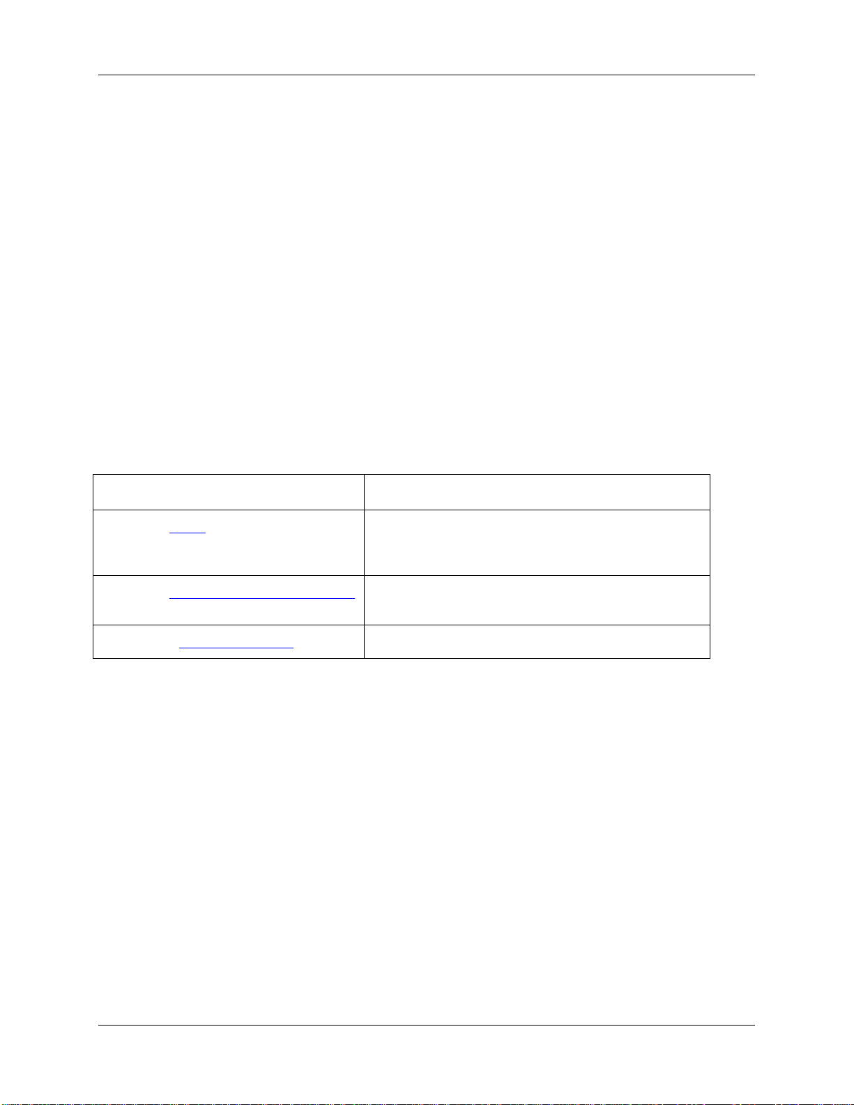
Chapter Description
Chapter 1: Setup
Chapter 2: HL-2000-FHSA Spec i fic ations
Appendix A: Bulb Replacement
Contains instructions for setting up the unit, enabling
automatic shutter control, and optimizing and
attenuating the optical power output.
Contains operating environment specifications, as
well as other physical details of the product.
Provides instructions for changing the bulb.
Product-Related Documentation
You can access documentation for Ocean Optics products by visitin g our website at
http://www.oceanoptics.com. Select Technical → Operating Instructions, then choose the appropriate
document from the available drop-down lists. Or, use the Search by Model Number field at the bott om
of the web page.
You can also access operating instructions for Ocean Optics products on the Software and Technical
Resources CD included with the system.
Engineering-level documentation is lo cated on our website at Technical → Engineering Docs.
000-10000-070-02-201307 iii
Page 8

About This Manual
Upgrades
Occasionally, you may find that you need Ocean Optics to make a change or an upgrade to your system.
To facilitate these changes, you must first contact Customer Support and obtain a Return Merchandise
Authorization (RMA) number. Please c ont act O cean Op ti cs for sp eci fi c inst ru cti ons wh en retu rn in g a
product.
iv 000-10000-070-02-201307
Page 9

Chapter 1
Setup
Overview
The following sections provide instructions on unpacking and setting up your HL-2000-FHSA Light
Source.
Before using the HL-2000-FHSA for the first time check for tr ansport damag e. Be sure to adhere to all
warnings on the unit and in this manual.
Unpacking the HL-2000-FHSA
► Procedure
1. Unpack your lamp assembly carefully. Dropping this instrument can cause permanent damage.
000-10000-070-02-201307 1
Page 10

1: Setup
2. Inspect the outside of the instr ument and make sure that there is no damage. Do not use the
instrument if damage is present. Contact you r dealer for repair or replacement information, i f
necessary.
3. Use this instrument in a clean laboratory environment.
Contents
Your HL-2000-FHSA package should contain the following:
HL-2000 Light Source
One IC -DB15-2 interface cable for shut te r ope ra tion
Setting Up the HL-2000-FHSA Light Source
Use the following procedure and refer to HL-2000-FSHA Diagrams to set up your light source.
► Procedure
Perform the steps below to set up your H L-2000-FHSA Light Source:
1. Plu g the po wer su pp l y into a wall ou tl et.
Power Supply
2. Plug the other end of the power supply cable into the socket of HL-2000-FHSA.
2 000-10000-070-02-201307
Page 11

1: Setup
HL-2000-FHSA Rear View
3. Connect the SMA connector of your fiber optic cable to the SMA plug s.
HL-2000-FHSA Right Side View
4. Turn the Halogen lamp on using the power swit ch on the rear of the HL-2000-FHSA.
HL-2000-FHSA Rear View
Enabling Automatic Shutter Control
The HL-2000-FHSA is equipped with a 15-pin TTL port on the rear of the unit that allows an external
source to cont r ol th e sh u tt er of the HL -2000-FHSA.
000-10000-070-02-201307 3
Page 12

1: Setup
► Procedure
To enable automatic shut t er control (TTL), perform the following steps:
1. Insert the supplied IC-DB-15-2 15 pin connector into the port on the rear of the HL-2000-FHSA.
HL-2000-FHSA Rear View
2. Move the shutter switch on the rear o f the unit into the ap propriate position to select the sh utter
mode.
• Open – Shutter open
• Close – Shutter closed
• TTL – Controlled by external TTL (High = Open, Low = Closed)
Note
Use Ocean Optics OOIBase32 software for automatic save dark.
Optimizing the Optical Power Out put
The HL-2000-FHSA is ad j ust ed at the factory to provide maximum power into a 200µm fiber. If a lower
optical power is requir ed or a different fiber (bundle) diameter is used, you can adjust the optical power of
the unit. Refer to HL-2000-FSHA Diagrams
► Procedure
Follow the steps below to adjust the optical power of the HL-2000-FHSA Light Source:
while using the following procedure.
1. Conn e ct a fib er opt ic spe c tr om ete r or an optic a l pow er m ete r to a fiber, and then conn ect th e oth e r
end of the fiber to the HL-2000-FHSA’s SMA plug.
4 000-10000-070-02-201307
Page 13

1: Setup
2. Loosen the blocking screw with the provided 1.3mm Allen wrench.
3. Sh ift the SMA socket to optimize the optical power of the HL-2000-FHSA.
4. Tighten the blocking screw to secure the SMA socket position.
Attenuating the Optical Power Output
The HL-2000-FHSA allows you to attenuate the optical output of the unit by adjusting the attenuation
screw.
Procedure
►
To attenuate the optical ou tput of the HL-2000-FHSA, follow the steps bel ow:
1. Ensure that the shutter switch on the rear of the unit is in the open position.
2. Loosen the fixture screw with the provided 2.0mm Allen wrench.
3. Tu rn the at tenu at ion scr e w until th e des ir e opti c al po wer is a chi ev ed.
4. Tigh ten the fix tu re s cre w wh en fin ish ed .
5. To a ttenuate the optical output of the HL-2000-FHSA, turn the attenuation-screw clockwise.
000-10000-070-02-201307 5
Page 14

1: Setup
Power Connector
Power Supply
HL-2000-FSHA Diagrams
Figure 1: HL-2000-FHSA Po wer Supply
6 000-10000-070-02-201307
Page 15

1: Setup
Power Socket
Power S w i tch
Rear Screw
Rear Screw
SMA Connector
Fixture Screw
Filter Holder
Shutter Mode Switch
Attenuation Screw
Rear Screw
15-Pin TTL Connector
Figure 2: HL-2000-FHSA Rear View
000-10000-070-02-201307 7
Figure 3: HL-2000-FHSA Side View
Page 16

1: Setup
Blocking Screw
Cooling Fan
Bottom
Plate Screw
Figure 4: HL-2000-FHS A Bottom View
8 000-10000-070-02-201307
Page 17

HL-2000-FHSA
HL-2000-FHSA-LL
HL-2000-FHSA-HP
Chapter 2
HL-2000-FHSA Specifications
This section provides information on the operating environment, physical controls, and dimensions of the
HL-2000-FHSA, as well as pin out s for the DB-15 connector. It also provides a parts list.
Specifications
Wavelength range 360 nm – 2400 nm
Stability 0.5 %
Drift <0.1% per hour
Time to stabilize Approximately 5 Minutes
Output to bulb 5V DC / 1,435A 5V DC / 0,970A 24V DC / 1,67A
Bulb life time 1.500 h 10.000 h 2000 h
Characteristic Focused
Shutter TTL max. 5Hz
DB-15 Connector PIN 13: TTL PIN 10: Ground
Bulb color temperature 2.960K 2.800K 3.000K
Room temperature 5°C – 35°C
Humidity 5 - 95% at 40°C
Output 7W 7W 20W
Weight Approximately 0.5 kg
Size 58 x 59 x 140 mm
000-10000-070-02-201307 9
Page 18

2: HL-2000 Specifications
Pinout Information
The following table contains pinout information for the HL-2000-FHSA Light Source:
Pin Description
1 na
2 na
3 na
4 na
5 na
6 na
7 na
8 na
9 na
10 Ground
11 na
12 na
13 TTL Signal – Shutter control
14 na
15 na
na = not applicable
10 000-10000-070-02-201307
Page 19

2: HL-2000 Specifications
Halogen light source with filter holder/shutter and attenuator
HL-2000-FHSA
Halogen light source, fan cooled, long life
HL-2000-FHSA-LL
Halogen light source High-Power with Attenuator and TTL-Shutter
HL-2000-FHSA-HP
Halogen spare bulb 2.960K/ 1.500 hrs
HL-2000-B
Halogen spare bulb 2.800K / 10.000 hrs
HL-2000-LL-B
Halogen spare bulb High-Power
HL-2000-HP-B
Pinout Diagram
Parts List
Spare Parts / Order Information Catalog Number
000-10000-070-02-201307 11
Page 20

2: HL-2000 Specifications
12 000-10000-070-02-201307
Page 21

Appendix A
Bulb Replacement
Overview
To order replace men t bulb s for th e H L-2000-FHS A, c onsult the Parts List.
WARNING
Before replacing the bulb in the HL-2000-FHSA, disconnect the lamp from your
power source and allow the unit to cool for at least twenty minutes, if necessary.
Replacing the Bulb
► Procedure
Refer to Figure 5 and perform the steps below to replace the bulb in the HL-2000-FHSA Light
Source:
1. Unplug the power connector from the power socket on the HL-2000-FHSA.
2. Loosen the screws on the rear of the unit with the provided 2.5mm Allen wrench.
3. Re move the rear of the HL-2000-FHSA and remove the electronics board from the unit, taking
particular care not to disconnect the fan wires.
4. Remove the screws from the bottom plate of the unit with the provided 1.3mm Allen key.
5. Remove the bulb from the HL-2000-FHSA.
6. Disconnect the wires from the connection block.
7. Replace the bulb and reconnect the wires to the connection block.
8. Slide the lamp into the housing and secure the housing with the bottom screw.
000-10000-070-02-201307 13
Page 22

A: Bulb Replacement
Block
Fan Wires
9. Slid e th e ele ct r oni cs b oard b ac k int o the H L -2000-FHSA, taking particular care to ensure t hat the
wires do not come into contact with the fan blades.
Connection
Rear / Electronics Board
Lamp
Housing
Figure 5: HL-2000-FHSA Bulb Replacement Diagram
14 000-10000-070-02-201307
Page 23

Index
bulb
replacement, 13
bulb replacement
diagram, 14
diagrams, 6
bottom vi ew, 8
bulb replacement, 14
pinout, 11
power supply, 6
rear view, 7
side view, 7
document
audience, iii
purpose, iii
summary, ii i
optical power
attenuating output, 5
optimizing output, 4
B
D
O
P
package contents, 2
parts list, 11
pinout
diagram, 11
pinouts, 10
product-related documentation, iii
S
setup, 1
shutter control, 3
specifications, 9
U
unpacking procedure, 1
upgrades, iv
W
warrant y, A
what's new, iii
000-10000-070-02-201307 15
Page 24

Index
16 000-10000-070-02-201307
 Loading...