

Page 1

Filter- and Cuvette-Holder with
Attenuator and TTL-Shutter
FHSA-TTL
Installation and Operation Manual
Document Number 000-10000-140-02-1209
Offices:
E-mail: Info@OceanOptics.com (General sales inquiries)
Ocean Optics, Inc.
830 Douglas Ave., Dunedin, FL, USA 34698
Phone 727.733.2447
Fax 727.733.3962
8 a.m.– 8 p.m. (Mon-Thu), 8 a.m.– 6 p.m. (Fri) EST
Ocean Optics Mikropack
Maybachstraße 11, D73760, Ostfildern, Germa
Phone
Fax
Info@Mikropack.de (Mikropack sales inquiries)
Orders@OceanOptics.com (Questions about orders)
TechSupport@OceanOptics.com (Technical support)
+49 (0)711 34 16 96-0
+49 (0)711 34 16 96-85
ny
000-00000-000-02-A
Page 2

Copyright © 2009 Ocean Optics, Inc.
All rights reserved. No part of this publication may be reproduced, stored in a retrieval system, or transmitted, by any means, electronic,
mechanical, photocopying, recording, or otherwise, without written permission from Ocean Optics, Inc.
This manual is sold as part of an order and subject to the condition that it shall not, by way of trade or otherwise, be lent, re-sold, hired out or
otherwise circulated without the prior consent of Ocean Optics, Inc. in any form of binding or cover other than that in which it is published.
Trademarks
Microsoft, Windows, Windows 95, Windows 98, Windows Me, Windows NT, Windows 2000, Windows XP and Excel are either registered
trademarks or trademarks of Microsoft Corporation.
Limit of Liability
Every effort has been made to make this manual as complete and as accurate as possible, but no warranty or fitness is implied. The information
provided is on an “as is” basis. Ocean Optics, Inc. shall have neither liability nor responsibility to any person or entity with respect to any loss or
damages arising from the information contained in this manual
Page 3

Table of Contents
About This Manual .............................................................................................................iii
Document Purpose and Intended Audience..............................................................................iii
What’s New in this Document ................................................................................................... iii
Document Summary..................................................................................................................iii
Product-Related Documentation ............................................................................................... iii
Upgrades ............................................................................................................................iii
Chapter 1: Setup...................................................................................1
Overview.............................................................................................................................1
Unpacking the FHSA-TTL Unit ..........................................................................................1
Contents .............................................................................................................................2
Setup ..................................................................................................................................2
Adjusting Optical Power .....................................................................................................3
Converting from Filter Holder to Cuvette Holder ...............................................................4
Inserting the Filter into the Filter Holder.............................................................................6
Inserting a Cuvette into the Cuvette Holder.......................................................................7
Chapter 2: FHSA-TTL Specifications .................................................9
Operating Environment ......................................................................................................9
Specifications .....................................................................................................................10
Pinout Information ..............................................................................................................10
Index ......................................................................................................11
000-10000-140-02-1209 i
Page 4

Table of Contents
ii 000-10000-140-02-1209
Page 5
About This Manual
Document Purpose and Intended Audience
This document provides you with an installation section to get your system up and running.
What’s New in this Document
This version of the Filter- and Cuvette-Holder with Attenuator and TTL-Shutter Installation and
Operation Manual
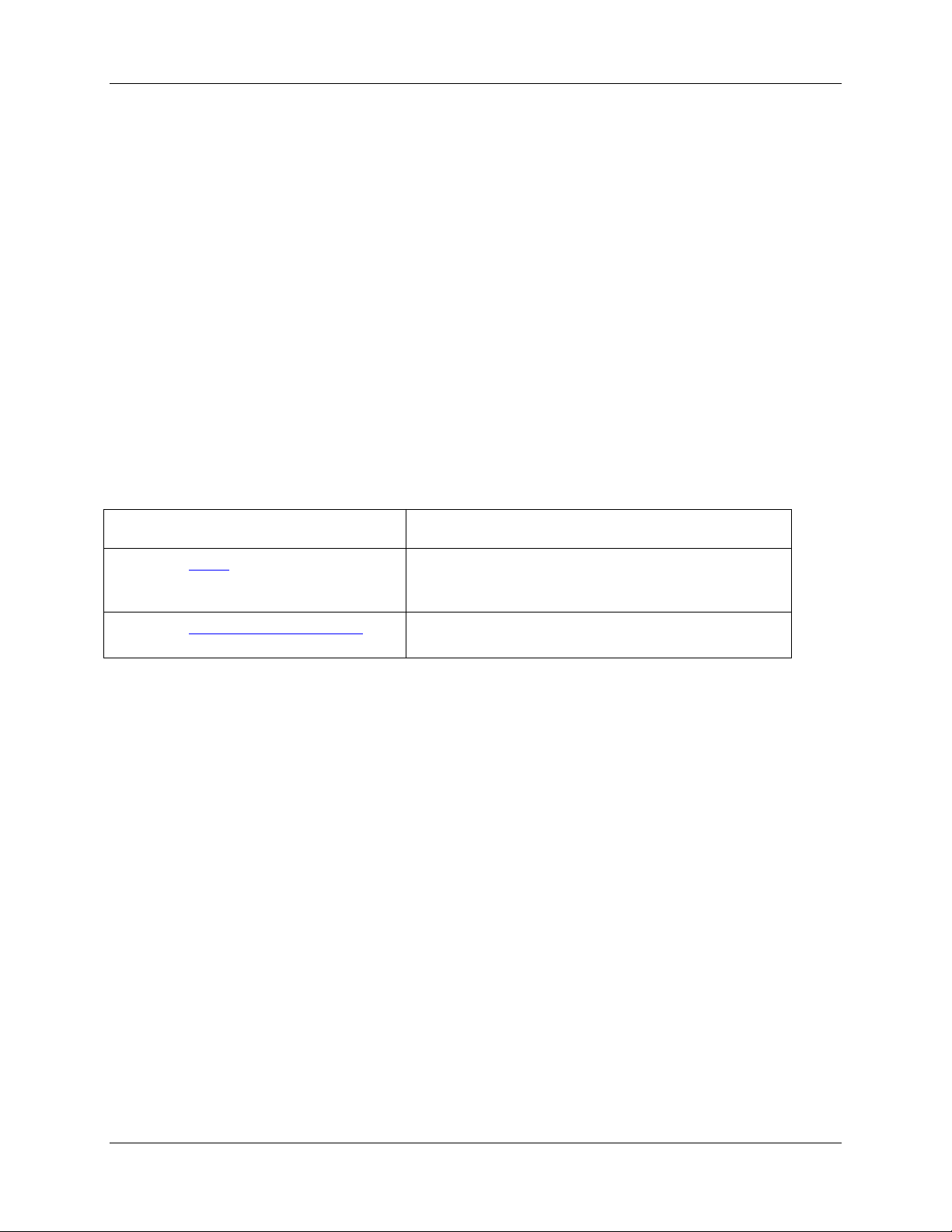
Document Summary
Chapter Description
updates the logo and contact information.
Chapter 1: Setup
Chapter 2: FHSA-TTL Specifications
Contains package contents and instructions for
unpacking, setting up and adjusting the optical power
of your FODS unit.
Contains operating specifications and pinout
information.
Product-Related Documentation
You can access documentation for Ocean Optics products by visiting our website at
http://www.oceanoptics.com. Select Technical → Operating Instructions, then choose the appropriate
document from the available drop-down lists. Or, use the
of the web page.
You can also access operating instructions for Ocean Optics products on the
Resources
Engineering-level documentation is located on our website at Technical → Engineering Docs.
CD included with the system.
Search by Model Number field at the bottom
Software and Technical
Upgrades
Occasionally, you may find that you need Ocean Optics to make a change or an upgrade to your system.
To facilitate these changes, you must first contact Customer Support and obtain a Return Merchandise
Authorization (RMA) number. Please contact Ocean Optics for specific instructions when returning a
product.
000-10000-140-02-1209 iii
Page 6

About This Manual
iv 000-10000-140-02-1209
Page 7

Chapter 1
Setup
Overview
The following sections provide instructions on unpacking, setting up and adjusting your Filter- and
Cuvette-Holder with Attenuator and TTL-Shutter (FHSA-TTL).
Unpacking the FHSA-TTL Unit
► Procedure
1. Unpack your new equipment carefully. Dropping this instrument can cause permanent
damage.
2. Inspect the outside of the instrument and make sure that there is no damage. Do not use the
instrument if damage is present. Contact your dealer for repair or replacement information, if
necessary.
3. Use this instrument in a clean laboratory environment.
000-10000-140-02-1209 1
Page 8

1: Setup
Contents
Your package should contain the following:
FHSA-TTL device
One IC-DB15-2 interface cable for shutter operation
One Ocean Optics Software and Technical Resources CD
Setup
► Procedure
To set up your FHSA-TTL device,
1. Plug the power supply into the main connection.
2. Plug the connector of the power supply into the 12 VDC Input connector of the FHSA-TTL
device.
3. Remove the SMA connectors protection caps.
4. Attach the SMA connectors on your fibers to the SMA plugs.
5. Plug in the IC-DB-15-2 cable into the TTL connector for automatic TTL-operation (cable
included).
6. Set the operating mode using the shutter switch.
2 000-10000-140-02-1209
Page 9

1: Setup
Shutter Switch Positions
Switch Position Action
OPEN Shutter open
CLOSE Shutter closed
TTL Operation by external TTL signal:
HIGH = Open
Low = Closed
Adjusting Optical Power
The FHSA-TTL is adjusted at the factory for maximum power. If lower optical power is required, you
can adjust it by turning the attenuation screw clockwise to decrease the power down to 0%.
FHSA-TTL Top View
► Procedure
Follow the steps below to adjust optical power:
1. Move the shutter switch to the OPEN position to open the shutter.
2. Connect a fiber optic spectrometer or an optical power meter to one side of the FHSA-TTL.
3. Loosen the locking screw with a hexagonal socket screw key (SW 2.0 mm).
4. Turn the attenuation screw clockwise to decrease optical power.
5. Tighten the locking screw when the optical power has been properly adjusted.
000-10000-140-02-1209 3
Page 10

1: Setup
Converting from Filter Holder to Cuvette Holder
The FHSA-TTL device can be used as either a filter holder or a cuvette holder. To convert the unit from
filter holder to cuvette holder, use the following procedure.
► Procedure
1. Turn the filter thumbwheel all the way to the end.
Filter Holder – Top View
2. Loosen the 74-UV-mount screw and unscrew it out along with the collimating lens.
4 000-10000-140-02-1209
Page 11

3. Unscrew the SMA Collimating assembly (74-UV, 74-UV-mount, filter thumbwheel, and
filterholder) for the filterholder and remove it.
1: Setup
4. Screw in the 74-UV into the 74-UV-mount for the cuvette holder.
5. Screw the 74-UV-mount for the cuvette holder into the FHSA-TTL.
000-10000-140-02-1209 5
Page 12

1: Setup
6. Dismount the filterholder by removing the screws.
7. Replace the filter holder with the cuvette holder.
8. Attach the cuvette holder to the unit with one of the screws.
Inserting the Filter into the Filter Holder
Filter Holder – Top View
► Procedure
1. Insert the filter into the filter slit.
2. Adjust the filter thumbwheel as desired.
6 000-10000-140-02-1209
Page 13

Inserting a Cuvette into the Cuvette Holder
Cuvette Holder – Top View
► Procedure
1. Insert the cuvette into the cuvette holder.
1: Setup
2. Adjust the cuvette using the plastic-tipped screws.
000-10000-140-02-1209 7
Page 14

1: Setup
8 000-10000-140-02-1209
Page 15

Chapter 2
FHSA-TTL Specifications
This section provides information on the environmental and physical specifications of the FHSA-TTL. It
also provides pinouts for the 15-pin connector.
Note
Modification of specifications and design to improve device performance are possible
without notice.
Operating Environment
The following table provides information on optimizing the operating environment of your FHSA-TTL
unit.
Operating Environment The FHSA-TTL Unit . . .
Moisture Is designed for operation in dry rooms only.
Ventilation Should be situated so that its location or position does not interfere
with proper ventilation.
Heat Should be situated away from any device that emits excessive heat.
Object and Liquid Entry Should be positioned so that objects do not fall on top of the unit.
Additionally, ensure that no liquids are spilled into the enclosure
through openings.
Power Sources Should be connected to an approved power supply, such as the
Mikropack 12 VDC 1250mA analog regulated power supply (PS12V/1.25A)
000-10000-140-02-1209 9
Page 16

2: FHSA-TTL Specifications
Specifications
Specifications Criteria
Spectral Range UV-VIS
Shutter Input TTL maximum 5 Hz
Power Requirements 12 VDC
Power Consumption Maximum 100 mA
Weight Approximately 600 g
Size 140 x 50 x 50 mm
Filter Holder Round or rectangular, width up to 7 mm
Cuvette Holder Standard (10 x 10 mm)
Pinout Information
The following figure contains pinout information for the TTL connector:
10 000-10000-140-02-1209
Page 17

Index
conversion, 4
cuvette
insert, 7
cuvette holder
convert, 4
insert cuvette, 7
document
audience, iii
purpose, iii
summary, iii
filter
insert, 6
filter holder
convert, 4
insert filter, 6
C
D
F
O
operating environment, 9
optical power
adjusting, 3
P
package contents, 2
pinouts, 10
product-related documentation, iii
S
setup, 1, 2
specifications, 9
U
unpacking procedure, 1
upgrades, iii
W
what's new, iii
000-10000-140-02-1209 11
Page 18

Index
12 000-10000-140-02-1209
 Loading...