

Page 1
Temperature-regulated Cuvette
Holder
CUV-TLC-50F
Installation and Operation Manual
Document Number 000-30000-000-02-0205
Offices:
E-mail: Info@OceanOptics.com (General sales inquiries)
Ocean Optics, Inc.
830 Douglas Ave., Dunedin, FL, USA 34698
Phone (727) 733-2447
Fax (727) 733-3962
8:30 a.m.–6 p.m. EST
Ocean Optics B.V. (Europe)
Nieuwgraaf 108 G, 6921 RK DUIVEN, The Netherlands
Phone 31-(0)26-3190500
Fax 31-(0)26-3190505
Info@OceanOpticsBV.com (European sales inquiries)
Orders@OceanOptics.com (Questions about orders)
TechSupport@OceanOptics.com (Technical support)
Page 2

Copyright © 2001-2005 Ocean Optics, Inc.
All rights reserved. No part of this publication may be reproduced, stored in a retrieval system, or transmitted, by any means, electronic,
mechanical, photocopying, recording, or otherwise, without written permission from Ocean Optics, Inc.
This manual is sold as part of an order and subject to the condition that it shall not, by way of trade or otherwise, be lent, re-sold, hired out or
otherwise circulated without the prior consent of Ocean Optics, Inc. in any form of binding or cover other than that in which it is published.
Trademarks
Microsoft, Windows, Windows 95, Windows 98, Windows Me, Windows NT, Windows 2000, Windows XP and Excel are either registered
trademarks or trademarks of Microsoft Corporation.
Limit of Liability
Every effort has been made to make this manual as complete and as accurate as possible, but no warranty or fitness is implied. The information
provided is on an “as is” basis. Ocean Optics, Inc. shall have neither liability nor responsibility to any person or entity with respect to any loss or
damages arising from the information contained in this manual
Page 3

Table of Contents
About This Manual .......................................................................................................... iii
Document Purpose and Intended Audience ............................................................................. iii
What’s New in this Document ................................................................................................... iii
Document Summary.................................................................................................................. iii
Product-Related Documentation ............................................................................................... iv
Upgrades......................................................................................................................... iv
Chapter 1: ......................................................................1Introduction
Overview.......................................................................................................................... 1
Features .......................................................................................................................... 2
System Setup .................................................................................................................. 2
Components .................................................................................................................... 3
Optional Equipment......................................................................................................... 3
Optical Components.................................................................................................................. 3
Additional Accessories ..............................................................................................................5
Packages for Specific Applications ...........................................................................................6
Chapter 2: ..........................................................................7Operation
Optics .............................................................................................................................. 7
Typical Configuration for Absorbance Measurements .............................................................. 7
Typical Configuration for Fluorescence Measurements............................................................ 8
Optical Adjustments................................................................................................................... 8
Converting an Imaging Lens into a Collimating Lens................................................................ 9
System Operation............................................................................................................ 9
Performance.................................................................................................................... 10
Temperature Equilibration ......................................................................................................... 11
Low Temperatures..................................................................................................................... 11
Temperature Ramping .............................................................................................................. 12
Error Conditions .............................................................................................................. 12
000-30000-000-02-0205 PRELIMINARY DRAFT i
Page 4

Table of Contents
Chapter 3: ...................................................................13Specifications
Specifications Table ........................................................................................................ 13
Temperature.................................................................................................................... 13
Variable Speed Magnetic Stirring.................................................................................... 14
Dry Gas Purge................................................................................................................. 14
Serial Interface ................................................................................................................ 14
Mechanical Diagram........................................................................................................ 15
Appendix A: ............................17Serial Control for the CUV-TLC-50F
Overview.......................................................................................................................... 17
Setup and Software Installation....................................................................................... 17
Uninstalling the Software........................................................................................................... 17
Serial Control from Other Programs ................................................................................ 18
The Example Programs................................................................................................... 18
Ramping Control ............................................................................................................. 19
Index.....................................................................................................21
ii 000-30000-000-02-0205
Page 5
About This Manual
Document Purpose and Intended Audience
This document provides you with an installation section to get your system up and running. In addition to
the Maxwell system installation and operation instructions, this manual also includes information for
locating the OOIBase32 installation instructions (see
What’s New in this Document
This version of the Temperature-regulated Cuvette Holder Installation and Operation Manual adds
performance data, new configuration drawings, and optional equipment.
Document Summary
Product-Related Documentation below).
Chapter Description
Chapter 1: Introduction Provides information on product features and
system setup.
Chapter 2: Operation Contains configuration information for absorbance
and fluorescence measurements, and optical
adjustments.
Chapter 3: System Operation Contains instructions for using the CUV-TLC-50F,
and a list of error conditions.
Chapter 4: Specifications Provides product specifications and a mechanical
drawing.
Appendix A: Serial Control for the
CUV-TLC-50F
Provides information specific to serial control via
the serial interface on the PC.
000-30000-000-02-0205 iii
Page 6

About This Manual
Product-Related Documentation
You can access documentation for Ocean Optics products by visiting our website at
http://www.oceanoptics.com. Select Technical → Operating Instructions, then choose the appropriate
document from the available drop-down lists. Or, use the Search by Model Number field at the bottom
of the web page.
You can also access operating instructions for Ocean Optics products on the Software and Technical
Resources CD included with the system.
Engineering-level documentation is located on our website at Technical → Engineering Docs.
Upgrades
Occasionally, you may find that you need Ocean Optics to make a change or an upgrade to your system.
To facilitate these changes, you must first contact Customer Support and obtain a Return Merchandise
Authorization (RMA) number. Please contact an Ocean Optics Application Scientist for specific
instructions when returning a product.
.
iv 000-30000-000-02-0205
Page 7
Chapter 1
Introduction
Overview
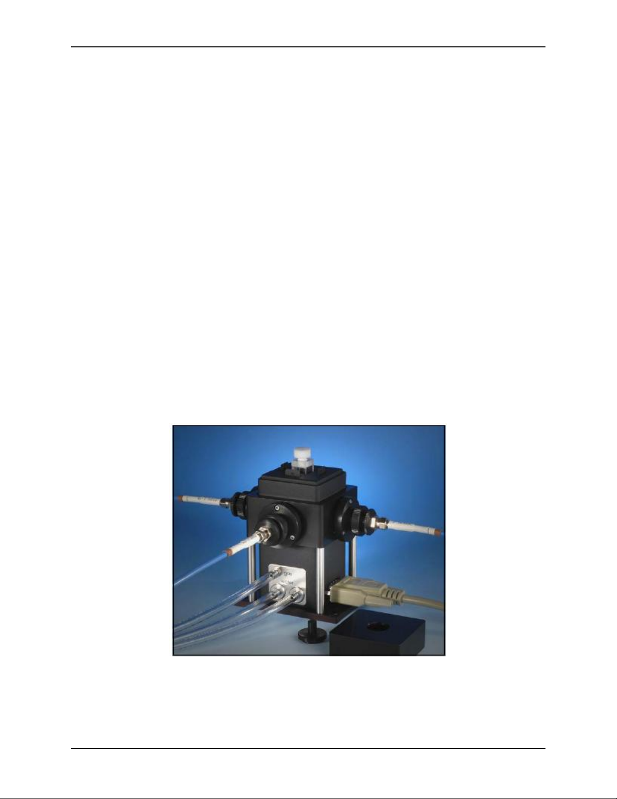
The CUV-TLC-50F Temperature-regulated Cuvette Holder is a high-quality, versatile sample chamber
with a Peltier temperature controller calibrated against a NIST-traceable thermometer. The device
controls the temperature of the holder from -40 °C to 85 °C and maintains a constant temperature within
±0.02 °C. The CUV-TLC-50F includes the cuvette holder and the external temperature controller box.
Both collimating and focusing lens systems are available in AR-coated fused silica. SMA 905 optical
fiber connectors are provided with the lens systems. To run the thermoelectric cooler efficiently, we offer
a simple water pump and water container.
The CUV-TLC-50F forms the core of a fiber optic spectroscopy system. The holder provides rapid and
precise control of the temperature of a standard 1 X 1-cm cuvette. Since the height of the optical
centerline (the center of the optical path through the cuvette) is 8.5 mm above the outside bottom of the
cuvette, the CUV-TLC-50F readily accommodates a variety of standard micro-cuvettes that depend on
this dimension for small volume work. Fibers and combined lenses can be attached at any combination of
the optical ports.
000-30000-000-02-0205 1
Page 8

1: Introduction
Features
Features of the CUV-TLC-50F include the following:
• Magnetic stirring (in the CUV-TLC-50F). A stir bar is included.
• Dry gas purge: Limits condensation and excludes oxygen from around the cuvette. Tubing for
water and gas connections is included.
• Optical slits: Control the illuminated volume. Several removable optical slits are included.
An optional PC-based CUV-TLC-ADP adapter package comes with Windows-compatible software that
allows you to remotely start a test sequence, operate the controller box and monitor experiments. Without
the CUV-TLC-ADP, you can control the cuvette holder’s temperature mechanically from the controller
box.
One side of the holder is open for visual inspection, or may be blocked with a blank slit. The other three
sides can be left open or fitted with a removable lens system. Both collimating and focusing lens systems
are available in either AR-coated BK7 glass or AR-coated fused silica and can be used in a variety of
configurations. Typically two collimating systems are used on opposite sides for absorbance
measurements, or two imaging lens assemblies are used at right angles for fluorescence measurements.
SMA 905 optical fiber connectors are provided with the lens systems.
System Setup
► Procedure
1. Firmly fasten the CUV-TLC-50F to your table using the holes in the base of the instrument.
2. Connect a water source to either one of the two hose barbs labeled “water” on the rear side of
the CUV-TLC-50F. Use a length of tubing with 1/8” (3mm) inside diameter such as the 3603
Tygon provided. Cooling water is required for the functioning of the thermoelectric cooler.
Tap water may be used. However, a more convenient source would be a circulating bath or a
small submersible pump in a container of water.
3. Connect tubing from the other hose barb to a drain or back into the source of circulating
water. Do not exceed an input water pressure of 25 psi (1.7 bar), as damage may occur inside
the TLC50.
4. Set and maintain a cooling water flow rate of about 200 – 300 ml per minute. This flow
should require a pressure of approximately 3 – 5 psi (0.2 – 0.3 bar). If a circulating bath is
used as the water source, it may not be possible to maintain this flow rate. However, a slower
rate will likely be adequate for low temperature work, if precooled circulating water is used.
5. If using dry gas, connect a source of dry gas (typically nitrogen or air that has passed through
a desiccant) using a length of tubing with 1/8” (3mm) inside diameter, to the hose barb
labeled “gas” on the side of the CUV-TLC-50F. A flow of gas must be used to prevent
condensation on the faces of the cuvette when working below the dew point temperature. Set
the dry gas flow rate to 50 – 200 cc/min.
6. Connect the Temperature Controller to a power source and to the CUV-TLC-50F using the
electrical cords provided.
2 000-30000-000-02-0205
Page 9
1: Introduction
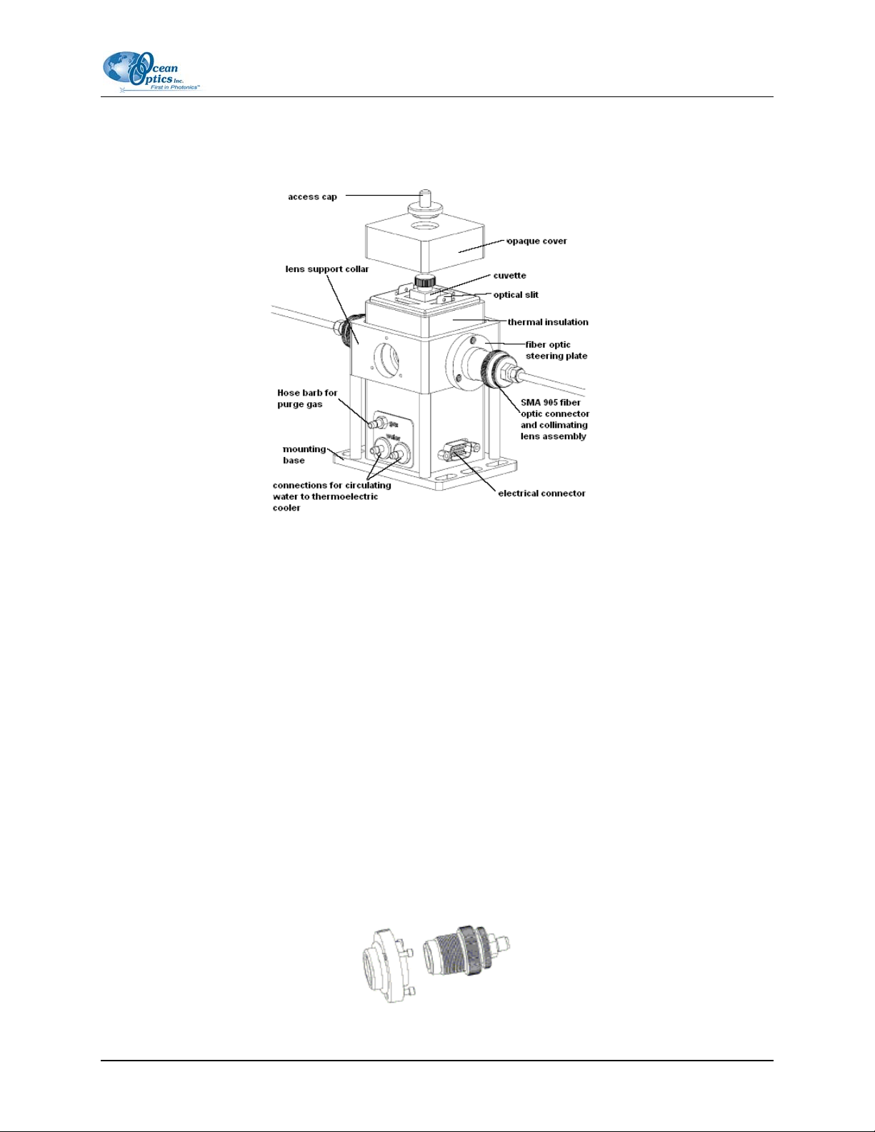
Components
CUV-TLC-50F Components
Optional Equipment
The following optional components and packages are also offered for specific applications. Contact
Ocean Optics for additional information.
Optical Components
CUV-TLC-CL Collimating Lens
The CUV-TLC-CL is an AR-coated fused silica collimating lens with SMA 905 connector and fiber optic
steering plate The CL-UV collimating lens collimates the diverging light from the end of a fiber and
passes it through the cuvette, or alternatively focuses collimated light onto the end of another fiber. The
collimating lens is mounted on a fiber optic steering plate that provides fine adjustments of the position of
the end of the fiber relative to the cuvette. The secondary knurled ring shown in the picture permits the
movement of the end of the fiber relative to the lens and cuvette, thus permitting an adjustment of the
degree of collimation. Collimating lenses are typically used for absorbance measurements.
000-30000-000-02-0205 3
Page 10

1: Introduction
CUV-TLC-IL Imaging Lens
The CUV-TLC-IL is an AR-coated fused silica imaging lens doublet with SMA 905 connector and fiber
optic steering plate. The CUV-TLC-IL imaging lens doublet is identical to the CUV-TLC-CL, except that
an additional lens is snapped into place to shorten the focal length. The imaging lens images the end of
the optical fiber into the cuvette, or focuses an image of the center of the cuvette onto a fiber. Again, the
steering plate can be used to adjust the position of the focused image inside the cuvette, and to maximize
the detected signal. The secondary knurled ring shown below permits movement of the focused image to
nearly any depth in the cuvette. Imaging lens doublets are usually used for fluorescence measurements,
although they are also useful for absorbance measurements on small sample volumes. The CUV-TLC-IL
can be easily converted to the CUV-TLC-CL by removing the attached Convergence lens.
CUV-TLC-MP Spherical Mirror Plug
The spherical mirror plug replaces a fiber with a spherical mirror that reflects an image of the illuminated
volume at the center of the cuvette back onto itself. Thus the mirror plug can return the excitation beam
back through the sample for a second pass, or permit one detector to collect the light from opposite sides
of the cuvette. For some fluorescence experiments, use of two mirror plugs can nearly quadruple the
measured signal. Purchase the spherical mirror plug to perform fluorescence measurements when weak
signals are anticipated.
CUV-TLC-FH Filter Holder Assembly
The CUV-TLC-FH filter holder assembly with collimating lens, SMA 905 connector, and fiber optic
steering plate places standard 1-inch filters in a light-tight compartment after a collimating lens. The lighttight cap backs away and the filters, mounted in a filter holder insert, are lifted out of the assembly. The
filter holder insert holds a single 1-inch round optical filter or a stack of such up to a thickness of 3/8 of
an inch. One insert is provided with the filter holder assembly, although other inserts can be purchased
separately. The filter holder assembly, mounted on a fiber optic steering plate, can be used directly in
place of a collimating lens. You can add a convergence lens to convert the filter holder assembly to an
imaging lens system.
4 000-30000-000-02-0205
Page 11

1: Introduction
Additional Accessories
The following additional accessories are available from Ocean Optics for your CUV-TLC-50F:
• CUV-TLC-ADP PC adapter package for remotely operating the cuvette holder.
The serial interface is used for external computer control of the temperature controller. The
option includes a serial cable, a control program, a library of functions in DLL form to simplify
serial communications with the controller, and a sample script for demonstrating the basic
functions of the sample holder. The control program simplifies the entry of individual commands,
permits the use of prewritten scripts for external operation of the controller and provides a
convenient plot of the sample holder temperature as a function of time. The serial interface option
is required for temperature ramping.
• CUV-TLC-SP steering plate that mounts a lens or mirror plug onto the cuvette holder.
The fiber optic steering plate attaches to one of the optical ports and provides the
receptacle for a lens system. Adjustment of three screws in the plate provides small
movements of the end of the optical fiber that can be used to optimize alignment of the
image within the cuvette, thus optimizing signal output. Each lens or mirror assembly
is provided with its own fiber optic steering plate. An additional plate can be purchased
to allow an optical component to be moved frequently or to place a mirror plug at an
unoccupied site.
• CUV-TLC-BATH water pump and bucket for efficient
operation of the thermoelectric cooler. The CUV-TLCBATH circulates cooling water to the thermoelectric device
in the sample holder. The accessory consists of a
submersible pump, a brass fitting and plastic bucket. Attach
the fitting to the pump and connect the sample holder via
1/8-inch I.D. vinyl tubing. Run the return water back into
the bucket. To lower the temperature, just add ice to the
bucket. Add enough ice, and the water in the bucket goes
immediately to 0.0ºC.
000-30000-000-02-0205 5
Page 12

1: Introduction
Packages for Specific Applications
Application Item Code Description Figure
UV/VIS
spectroscopy
Fluorescence CUV-TLC-FLKIT CUV-TLC 50F cell holder, two CUV-
UV/VIS and
fluorescence
CUV-TLC-ABSKIT CUV-TLC 50F cell holder, two CUV-
TLC-CL collimating lenses (with SMA
fiber optic connectors, lenses and
steering plates), CUV-TLC-ADP serial
interface and CUV-TLC-BATH water
pump with bucket.
TLC-IL imaging lenses (with SMA fiber
optic connectors, lenses and steering
plates), two CUV-TLC-MP mirror
plugs, two additional CUV-TLC-SP
steering plates, CUV-TLC-ADP serial
interface and CUV-TLC-BATH water
pump with bucket.
CUV-TLC-MPKIT CUV-TLC-50F cell holder, two CUV-
TLC-IL imaging lenses, two CUV-TLCCL collimating lenses, two CUV-TLCMP mirror plugs, CUV-TLC-ADP serial
interface and CUV-TLC-BATH water
pump with bucket.
6 000-30000-000-02-0205
Page 13

Chapter 2
Operation
Optics
The CUV-TLC-50F provides ports for viewing or illuminating 1-cm square cuvettes from four directions.
Lenses are available to purchase separately to allow you to choose the best lenses for your application.
For absorbance and transmission measurements, position two CUV-TLC-CL Collimating Lenses at 180°.
For fluorescence applications, position two CUV-TLC-IL Imaging Lenses at 90° and position two CUVTLC-MP Mirror Plugs in the remaining two collimator positions to redirect energy to the sample or into a
lens.
• Collimating Lens—The Collimating Lens system, containing a single lens, collimates the fiber
output or focuses collimated light onto the end of another fiber. The collimating lens system is
typically used in absorption measurements.
• Imaging Lens—The Imaging Lens system, containing two lenses, focuses an image of the end
of the fiber into the cuvette, or light in the center of the cuvette onto another fiber (magnification
of approximately one). For added versatility, the second lens of the Imaging Lens system may be
removed so that it may be used as a Collimating Lens. The Imaging Lens system is typically used
in fluorescence measurements.
Typical Configuration for Absorbance Measurements
To measure Absorbance, a single collimating lens is placed on each side of the cuvette. In the following
figure, lenses and cuvette are shown in blue. Note that each lens holder has an alignment adjustment as
well as focusing capability.
CUV-TLC-50F Typical Configuration for Absorbance Measurements
000-30000-000-02-0205 7
Page 14

2: Operation
Typical Configuration for Fluorescence Measurements
To measure fluorescence, Imaging Lens systems are placed at 90 degrees to each other. The first lens
system focuses the light as a small image inside the cuvette Emitted light from this small illuminated
volume is then focused at a right angle onto the second fiber. Mirrors can be mounted opposite each lens
system, nearly quadrupling measured light intensities.
CUV-TLC-50F Typical Configuration for Fluorescence Measurements
The following figure shows the components of an imaging lens system.
Components of an Imaging Lens System
Optical Adjustments
The fiber position adjustment screws use the steering plate to compress a soft o-ring. They may be used to
wobble the end of the fiber horizontally and vertically about its position and can substantially enhance
optical throughput. Take care not to over compress the o-ring. Alternatively, no adjustment is possible if
the steering plate is not in contact with the o-ring. Screwing in or unscrewing the horizontal fiber position
knob may vary the distance between the end of the fiber and the center of the cuvette.
8 000-30000-000-02-0205
Page 15

2: Operation
Caution
Be sure to first loosen the fiberoptic SMA 905 connection, so as not to apply torsion
to the fiber.
This adjustment varies the position of focus in the sample when desired for specific experiments, or to
compensate for lens aberrations to maximize optical throughput. For normal operation the distance
between the knurled ring on the horizontal fiber position knob should be set 1/8 inch from the knurled
ring on the first lens holder (see the following figure).
Imaging and Collimating Lenses
Converting an Imaging Lens into a Collimating Lens
The second lens of the imaging lens system is simply snapped onto the end of a collimating lens (see
figure above). To remove the second lens, use a piece lens tissue to prevent your fingers from touching
the lens. With the lens tissue in your hand, firmly grasp the second lens holder and snap it off of the
collimating lens.
System Operation
► Procedure
1. Turn on the power to the CUV-TLC-50F system using the switch located on the left side of
the rear panel of the temperature control unit.
2. Place the liquid sample in a standard 1 x 1-cm square fluorescence cuvette to reach a height
of 22 mm.
000-30000-000-02-0205 9
Page 16

2: Operation
Note
The CUV-TLC-50F is intended to hold a cuvette with a standard wall thickness of
1.25 mm and total width of 12.5 mm. Cuvettes with unusually thick walls will not
properly fit and may damage the holder. Also, unusually short cuvettes will be difficult to
remove after being pushed all of the way to the bottom of the holder.
3. Place the cuvette and sample in the sample holder.
4. Use the provided optical slits or blanks around the cuvette in a manner that correctly limits
the excitation and emission light.
5. If needed, place the magnetic stir bar in the cuvette and turn the magnetic stirrer knob located
on the front of the temperature control until the desired speed is reached.
6. Place the opaque plastic cover over the cuvette holder.
7. Place the access lid in the hole in the plastic cover.
8. Set the target temperature using the up/down buttons located to the right of the display
window. The normal temperature range is -10 °C to +80 °C, although temperatures from –
40 °C to +85 °C may be used under special circumstances (see
Specifications).
Temperature in Chapter 3:
9. Briefly depressing either the up or down button displays the target temperature. Otherwise,
the current temperature will be displayed.
10. To begin controlling the temperature, press the Run/Stop button located to the left of the
display. Pressing the Run/Stop button a second time turns temperature control off.
11. When the sample holder approaches the target temperature, the red light (located on the upper
left corner of the front panel of the temperature controller) flashes slowly.
12. When the sample holder reaches within ± 0.02 °C of the target temperature, the red light will
remain constant.
13. After measurements are completed, depress the run/stop button to stop temperature control,
and turn off power and water sources.
Performance
The graphs in this section show typical performance results for the CUV-TLC-50F under the following
conditions:
Temperature Equilibration
•
Low Temperatures
•
Temperature Ramping
•
10 000-30000-000-02-0205
Page 17

2: Operation
Temperature Equilibration
The serial control option was used to automatically cycle the CUV-TLC-50F through a series of
temperatures. The blue line shows the resulting temperature of the sample holder next to one of the
optical ports. The red line shows the temperature measured inside a cuvette. The cuvette, containing
ethylene glycol and water, was stirred using the magnetic stirring feature of the CUV-TLC-50F. Note the
rapid changes in sample holder temperature, followed in a few minutes by the temperature equilibration
of the sample.
Low Temperatures
To go to low temperature, additional insulation was applied to the CUV-TLC-50F and the unit was
connected to a refrigerated water bath containing a methanol and water mixture at approximately -
13.00 °C. The sample holder was equilibrated at 0.00 °C, taken to -20.00 °C, and then taken down to
-40.00 °C. Dropping the sample holder temperature from 0.00 to -20.00 °C required about 4 minutes.
Dropping from -20.00 °C to -40.00 °C required about 20 minutes.
000-30000-000-02-0205 11
Page 18

2: Operation
Temperature Ramping
Each of the sample holders from Quantum Northwest has a function for temperature ramping
programmed into its microcontroller. The user first allows equilibration at a particular temperature. To
initiate the ramp, the user then specifies a final temperature and increments for temperature and time. The
serial control option, allowing external control from a computer, is required for temperature ramping.
Error Conditions
Rapid flashing of the red light indicates an error condition. The common errors that will display are the
following:
• Error conditions E5, E6 and E7 – Check Cables. One or more of these error conditions is
likely to arise if the electrical connection between the Temperature Controller and the CUV-TLC50F is not secure. In this case, turn off the power to the unit, check the cable, turn on the power,
and resume work.
• Error condition E8 – Low water flow. This error condition indicates that the heat exchanger
on the thermoelectric cooler is getting too warm. This heating will occur if insufficient cooling
water is flowing into the device. Error condition E8 will automatically shut down temperature
control to prevent damage to the unit. If this occurs, improve cooling water flow and restart
temperature control.
12 000-30000-000-02-0205
Page 19

Specifications
Specifications Table
Specification Value
Temperature -40 to 85 °C
Precision ±0.02 °C
Reproducibility ±0.05 °C
Chapter 3
Maximum Luminated Area (h x w) 12 x 10 mm
Height of Optical Center Above Table 70 mm
Optical Center Above Bottom of Cuvette 8.5 mm
Magnetic Stirring yes
Dry Gas Purge yes
Temperature
Thermoelectric temperature control maintains the sample to a precision of ±0.02 °C within a range of
-40.00 °C to +85.00 °C. Depending on the humidity and ambient temperature (with dry gas purge) the
CUV-TLC-50F will operate down to about -10 °C without the formation of frost on the optical
components. Below this temperature, the CUV-TLC-50F requires additional insulation. We recommend
that the sample holder be carefully wrapped in bubble wrap or similar packing materials. Such materials
are inexpensive and function well. Very low temperature operation (down to -40 °C) requires the use of
precooled circulating water of a temperature within about 25 degrees of the target temperature. It will also
operate safely between 80 °C and 85 °C, although such high temperatures may adversely effect the
lifetime of the thermoelectric device. Temperatures of the sample holder are reproducible within
±0.03 °C. Reproducibility represents the temperature range, expressed as ± one standard deviation, over
which the temperature of the cuvette holder may vary from hour-to-hour or day-to-day as measured by a
NIST-traceable thermometer. Calibration data is provided with each sample holder. For experiments in
which knowledge of the exact sample temperature is critical, independent verification is required.
000-30000-000-02-0205 13
Page 20

3: Specifications
Variable Speed Magnetic Stirring
Variable speed magnetic stirring is provided for experiments in which it is important to rapidly remove
photoproducts from the illuminated volume. A stir bar is included.
Dry Gas Purge
A dry gas purge is provided. The gas travels through the base of the cuvette holder for temperature
equilibration and then blows onto each of the four faces of the cuvette. The gas purge minimizes
condensation on optical surfaces. An opaque cap with access hole covers the top of the cuvette to provide
isolation from the ambient environment.
Serial Interface
An optional serial interface is available for remote computer control (see Appendix A: Serial Control for
the CUV-TLC-50F
).
14 000-30000-000-02-0205
Page 21

3: Specifications
Mechanical Diagram
000-30000-000-02-0205 15
Page 22

3: Specifications
16 000-30000-000-02-0205
Page 23

Appendix A
Serial Control for the
CUV-TLC-50F
Overview
Serial Control permits the remote temperature control via a serial interface on a computer using a
Windows operating system. The option consists of a cable that connects the Temperature Controller with
the computer, and software. The software includes QNW_SC.exe, a sample control program that enables
control, and recovers and plots temperature data. For those who wish to write their own control programs,
example programs and libraries of functions are provided for use with both Borland and Microsoft
development systems.
Setup and Software Installation
► Procedure
1. Use the provided cable to connect from the lower (9-pin) connector on the back of the
temperature controller to a serial interface of your computer (typically COM1).
2. Place the installation CD in the computer’s CD drive and run Setup.exe from the CD. All
files will be placed in the directory specified during installation (default is C:\QNW Serial
Control), except for QnwSerial.DLL, which will be installed in the Windows System
directory.
3. To check the interface, run the program QNW_SC.exe. For instructions on how to use the
program, use the program’s Help system.
Uninstalling the Software
To uninstall the Serial Control Program files, use the “Add/Remove Programs” control panel by selecting
“QNW” from the list.
000-30000-000-02-0205 17
Page 24

A: Serial Control for the CUV-TLC-50F
Serial Control from Other Programs
It may be useful to have temperature control for the CUV-TLC-50F system from other programs (for
example data acquisition programs). The installation CD includes code for a simple C++ program that
illustrates how to use QnwSerial.DLL for serial communications with the TLC 50™ hardware.
QnwSerial.dll provides functions that simplify opening and closing serial ports, and sending and receiving
data over a serial connection. This DLL was developed with Borland C++ Builder 3. QnwSerial.dll can
only be used by 32-bit programs. The “Borland Example” and “Microsoft Example” directories contain
the code and project files required by Borland C++, version 5.02, and Microsoft Developer Studio Visual
C++, version 4.0, respectively, to generate the application. If you have either of these development
systems (or newer versions) installed on your computer, you should be able to open the projects
(QnwExample.ide or QnwExample.mdp files) and compile and link them to generate the example
programs. You will probably need to modify the project directories for Borland’s header and library files
in the Borland project so that the system can find the standard Borland files.
The .C and .H files for the Microsoft Example differ from those for the Borland Example in minor ways
as described below. For the Microsoft Example, the QnwSerial DLL function prototypes and function
calls include an added underscore as the first character of the function names.
One of the standard include lines differs between the two examples, <DIR.H> for Borland and
<DIRECT.H> for Microsoft.
In several of the calls to SendDlgItemMessage() the parameter -1 for Borland was changed to
(WPARAM)(-1) for Microsoft to suppress a warning message during compilation in the latter
development system. The line “#pragma argsused” is included before two of the function definitions only
for Borland, again to suppress a warning message during compilation.
The Example Programs
Copies of the resulting executable files, QnwExample.exe and QnwExampleM.exe, are included if you
installed the example programming files (“typical” installation choice).
When the programming example is started, it obtains the information needed for connecting to and
configuring a serial port from a command list file, QnwExample.lst. If this list file does not exist in the
startup directory, default settings are used and a QnwExample.lst file will be created which includes those
settings when the program is closed. You can modify this information to change the serial port setup to be
used the next time the program is started. The setup line is in the form of a DOS “mode” command for
configuring a serial port — “COM1:19200,N,8,1” — and must be the only data on the first line of the file.
In the example line above, COM1 specifies the serial port to be used (typically COM1, COM2, etc., but
some computers may require different designations). The remaining parameters specify a baud rate of
19200, no parity, 8 data bits and no stop bits, respectively. The parameters “19200,N,8,1” are correct for
the CUV-TLC-50F, so you should only need to consider changing the port designation if COM1 does not
work.
18 000-30000-000-02-0205
Page 25

A: Serial Control for the CUV-TLC-50F
The list file also may contain a list of command lines which QnwExample loads and inserts into a
program drop down list to give the user access to the commands. To use the program, the user either
chooses one of the commands from the drop down list (and possibly edits it) or enters a command directly
into the edit control provided. That command is sent out the serial port when the user presses the “Send
Command” button. QnwExample displays the command at the top of a large display window and
subsequently displays any information received through the serial connection. The program also provides
a means of deleting commands from the drop down list and for adding new or modified commands to the
list. These changes are saved to the list file when the program exits. A “Start/Stop Logging” button is
provided to enable/disable logging into a file named QnwExample.log. All information displayed in the
large text window is logged as it appears when logging is enabled.
The command list provided with the examples (QnwExample.lst) includes many of the valid command
forms for the CUV-TLC-50F. Each command is annotated to the right of the command for convenience.
Note, however, that the annotations are possible only because the CUV-TLC-50F ignores any text
received that is not included between square brackets.
Ramping Control
Linear temperature changes may be controlled through the ramping option in the Serial Control software.
Two parameters, RT (Ramping Temperature – the temperature increment) and RS (Ramping Seconds –
the time increment) control the rate of temperature change. Normal temperature control will be replaced
by ramping only if both the RT and RS values are non-zero.
To create a temperature ramp, equilibrate the sample holder at the starting temperature. Briefly, stop
temperature control and set the RT and RS values. Set the target temperature to the final temperature
desired at the end of the ramp and restart temperature control.
RS must be an integer between 1 and 64000 seconds. RT must be an integer between 1 and 32000 in units
of hundredths of a °C.
Table 1: Serial Commands
Command Response
[F1 SS +]
[F1 SS -]
[F1 TC +]
[F1 TC -]
[F1 TT S 23.1]
[F1 TT ?]
[F1 TT 71.3]
Turn stirrer on (stir rate must be set manually)
Turn stirrer off
Turn temperature control on
Turn temperature control off
Set target temperature to 23.1° C
Query: What is the current target temperature?
Reply: Target temperature is 71.3° C
000-30000-000-02-0205 19
Page 26

A: Serial Control for the CUV-TLC-50F
Table 1: Serial Commands (Cont’d)
Command Response
[F1 IS ?]
[F1 IS 0+-S]
[F1 IS +5] Automatically report instrument status every 5 seconds
[F1 IS +] Automatically report instrument status whenever it changes (e.g., due
[F1 IS -] Stop, periodic or automatic reports of instrument status
[F1 CT ?]
[F1 CT 22.8]
[F1 ER +]
[F1 ER -]
Query: What is the current instrument status?
Reply: no unreported error (0 or 1)
temperature control is on (+ or -)
temperature is stable (S or C)
stirrer is off (+ or -)
to manual changes at controller)
Query: report the current temperature
Reply: the current temperature is 22.8° C
Automatically report errors when they occur
Stop automatic error reports
Ramping Commands
[F1 RS S XX] Set Ramping Seconds, the time increment of the ramp rate (positive
integer in seconds)
[F1 RT S XX] Set Ramping Temperature, the temperature increment of the ramp
rate (positive integer in hundredths of a °C)
When the Controller is restarted (by being powered off and back on again), it automatically sends the
message [F1 IS R] to notify the program of the restart.
20 000-30000-000-02-0205
Page 27

Index
A
absorbance measurements, 7
accessories, 5
B
bath, 5
C
collimating lens, 3, 9
components, 3
configuration
absorbance measurements, 7
fluorescence measurements, 8
CUV-TLC-ABSKIT, 6
CUV-TLC-ADP, 5
CUV-TLC-BATH, 5
CUV-TLC-CL, 3
CUV-TLC-FH, 4
CUV-TLC-FLKIT, 6
CUV-TLC-IL, 4
CUV-TLC-MP, 4
CUV-TLC-MPKIT, 6
CUV-TLC-SP, 5
E
error conditions, 12
example programs, 18
F
features, 2
filter holder assembly, 4
fluorescence, 6
fluorescence measurements, 8
I
imaging lens, 4, 9
L
lens, 9
lens conversion, 9
low tempertures, 11
M
magnetic stirring, 14
D
document
audience, iii
purpose, iii
summary, iii
dry gas purge, 14
000-30000-000-02-0205 21
mechanical diagram, 15
O
optical adjustments, 8
optics, 7
Page 28

Index
P
T
PC adapter, 5
performance, 10
product-related documentation, iv
purge
dry gas, 14
temperature, 13
temperature equilibration, 10
temperature ramping, 11
U
R
upgrades, iv
ramping commands, 20
ramping control, 19
UV/VIS spectroscopy, 6
W
S
what's new, iii
serial commands, 19
serial control, 17
from other programs, 18
setup and software installation, 17
uninstalling software, 17
serial interface, 14
specifications, 13
spherical mirror plug, 4
steering plate, 5
system operation, 9
system setup, 2
22 000-30000-000-02-0205
 Loading...