

Page 1
OPERATING AND INSTALLATION
INSTRUCTIONS OF
BUILT-IN HOB
EN
OCEACPM2G2V
Page 2

Dear Customer,
Our goal is to offer you products with high quality that exceed your expectations.
Your appliance is produced in modern facilities carefully and particularly tested for
quality.
This manual is prepared in order to help you use your appliance that is manufactured
by the most recent technology, with confidence and maximum efficiency.
Before using your appliance, carefully read this guide that includes the basic
information for right and safe installation, maintenance and use. Please contact to
the nearest Authorized Service for the installation of your product.
CE Declaration of conformity
This appliance has been designed to be used only for home cooking. Any other use
(such as heating a room) is improper and dangerous.
This appliance has been designed, constructed, and marketed in compliance with:
• Safety requirements of the "Gas" Directive 2009/142/EC;
• Safety requirements of the "Low voltage" Directive 2006/95/EC;
• Safety requirements of the "EMC" Directive 2004/108/EC;
• Requirements of the Directive 93/68/EC.
Page 3

2
Note:All figures in manual are schematic.
CONTENTS:
1. BRIEF PRESENTATION OF PRODUCT
2. WARNINGS
3. INSTALLATION AND PREPARATIONS FOR USE
3.1
3.2
3.3
3.4 Gas conversion
Electrical Connection Of Your Hob
4. USE OF YOUR PRODUCT
4.1 Use of gas burners
4.2
4.3
5. CLEANING AND MAINTENANCE
5.1 Cleaning
5.2 Maintenance
6. SERVICE AND TRANSPORT
6.1
6.2 Information related to the transport
Environment where your appliance will be installed
Installation of product
Gas connection
3.5
Control of the hob burners
Control of the electric hobs
Basic troubleshooting before contacting service
4.4 Accesorries
Page 4
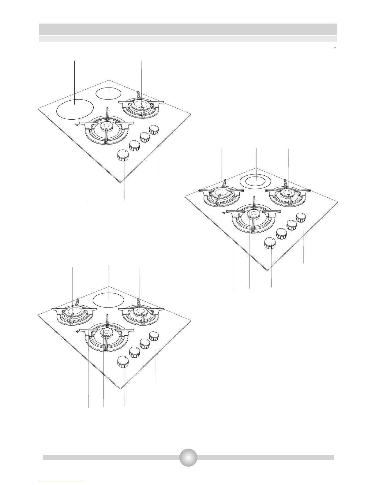
1.BRIEF PRESENTATION OF PRODUCT
* The appearance of your hob may be different than the model shown above due to its configuration.
12- Semi-Rapid Burner
3- Auxillary Burner
4- Rapid Burner
5- Control Knobs
67- Worktop
8-Pan Support
9-
Electrical Heater (145 mm)
Electrical Heater (180 mm)
Electrical Heater (Dual 180 mm)
1 4
7
6
3
5
8
2
7
5
3
4
8
9
7
5
2
3
4
6
8
3
Page 5

SAFETY WARNINGS
READ THESE INSTRUCTIONS CAREFULLY AND COMPLETELY BEFORE USING YOUR APPLIANCE, AND KEEP IT IN A
CONVENIENT PLACE FOR REFERENCE WHEN NECESSARY.
THIS MANUAL IS PREPARED FOR MORE THAN ONE MODEL IN COMMON. YOUR APPLIANCE MAY NOT HAVE
SOME OF THE FEATURES THAT ARE EXPLAINED IN THIS MANUAL. PAY ATTENTION TO THE EXPRESSIONS THAT
HAVE FIGURES, WHILE YOU ARE READING THE OPERATING MANUAL.
General Safety Warnings:
Your appliance is produced in accordance with all applicable local and international standards and regulations.
Maintenance and repair work must be made only by authorized service technicians. Installation and repair work
that is carried out by unauthorized technicians may endanger you. It is dangerous to alter or modify the
specifications of the appliance in any way.
Prior to installation, ensure that the local distribution conditions (nature of the gas and gas pressure or
electricity voltage and frequency) and the adjustments of the appliance are compatible. The adjustment
conditions for this appliance are stated on the label.
CAUTION: This appliance is designed only for cooking food and is intended for indoor domestic household use
only and should not be used for any other purpose or in any other application, such as for non-domestic use or
in a commercial environment or room heating.
This appliance can be used by children aged from 8 years
and above and persons with reduced physical, sensory or
mental capabilities or lack of experience and knowledge if
they have been given supervision or instruction concerning
use of the appliance in a safe way and understand the
hazards involved. Children shall not play with the appliance.
Cleaning and user maintenance shall not be made by
children without supervision.
This appliance is not connected to a combustion products evacuation device. It shall be installed
and connected in accordance with current installation regulations. Particular attention shall be
given to the relevant requirements regarding ventilation.
If after 15 s the burner has not lit, stop operating the device and open the compartment door
and/or wait at least 1 min before attempting a further ignition of the burner.
These instructions are only valid if the country symbol appears on the appliance. If the symbol does
not appear on the appliance, it is necessary to refer to the technical instructions which will provide
the necessary instructions concerning modification of the appliance to the conditions of use of the
country.
WARNING: The appliance and its accessible parts become
hot during use. Care should be taken to avoid touching
heating elements. Children less than 8 years of age shall be
kept away unless continuously supervised.
4
Page 6

5
SAFETY WARNINGS
WARNING: Unattended cooking on a hob with
fat or oil can be dangerous and may result in
fire. NEVER try to extinguish a fire with water,
but switch off the appliance and then cover flame
e.g. with a lid or a fire blanket.
WARNING: Danger of fire: do not store items on
the cooking surfaces.
WARNING: If the surface is cracked, switch off
the appliance to avoid the possibility of electric
shock.
For hobs incorporating a lid, any spillage should
be removed from the lid before opening. And
also the hob surface should be allowed to cool
before closing the lid.
The appliance is not intended to be operated by
means of an external timer or separate remotecontrol system.
Do not use harsh abrasive cleaners or sharp
metal scrapers to clean the oven door glass and
other surface since they can scratch the surface,
which may result in shattering of the glass or
damage to the surface.
Do not use steam cleaners for cleaning the
appliance.
All possible security measures have been taken to ensure your safety. Since the glass may
break, you should be careful while cleaning to avoid scratching. Avoid hitting or knocking on
the glass with accessories.
Page 7

6
SAFETY WARNINGS
Ensure that the supply cord is not wedged during the installation. If the supply cord is damaged, it
must be replaced by the manufacturer, its service agent or similarly qualified persons in order to
prevent a hazard.
Installation Warnings:
Do not operate the appliance before it is fully installed.
The appliance must be installed by an authorized technician and put into use. The producer is not
responsible for any damage that might be caused by defective placement and installation by
unauthorized people.
When you unpack the appliance, make sure that it is not damaged during transportation. In case of
any defect; do not use the appliance and contact to the authorized maintenance service
immediately. As the materials used for packaging (nylon, staplers, styrofoam...etc) may cause
harmful effects to children, they should be collected and removed immediately.
Protect your appliance against atmospheric effects. Do not expose it to effects such as sun, rain,
snow etc.
The surrounding materials of the appliance (cabinet) must be able to withstand a temperature of
min 100°C.
During usage :
Do not put flammable or combustible materials, in or near the appliance when it is operating.
Do not leave the cooker while cooking with solid or liquid oils. They may catch fire on condition of
extreme heating. Never pour water on to flames that are caused by oil. Cover the saucepan or
frypan with its cover in order to choke the flame that has occured in this case and turn the cooker
off.
Always position pans over the centre of the cooking zone, and turn the handles to a safe position so
they cannot be knocked or grabbed.
If you will not use the appliance for a long time, plug it off. Keep the main control switch off. Also
when you do not use the appliance, keep the gas valve off.
Make sure the appliance control knobs are always in the "0" (stop) position when it is not used.
CAUTION: The use of a gas cooking appliance results in the production of heat, moisture and
products of combustion in the room in which it is installed. Ensure that the kitchen is well
ventilated especially when the appliance is in use, keep natural ventilation holes open or install a
mechanical ventilation device (mechanical extractor hood).
Prolonged intensive use of the appliance may call for additional ventilation, for example opening of
a window, or more effective ventilation, for example increasing the level of mechanical ventilation
where present.
During cleaning and maintenance:
Always turn the appliance off before operations such as cleaning or maintenance. You can do it
after plugging the appliance off or turning the main switches off.
Do not remove the control knobs to clean the control panel.
TO MAINTAIN THE EFFICIENCY AND SAFETY OF YOUR APPLIANCE, WE RECOMMEND YOU ALWAYS
TO USE THE ORIGINAL SPARE PARTS AND TO CALL ONLY OUR AUTHORIZED SERVICES IN CASE OF
NEED.
Page 8
7
3. INSTALLATION AND PREPARATIONS FOR USE
This modern, functional and practical cooker, that was manufactured with the parts and
materials of highest quality, will meet your cooking needs in every aspect. You must surely
read this manual so that you don't have any problem in future and to be able to have
satisfactory results. The following information are the required rules for right installation and
service processes. It must be read especially by the technician who will install the appliance
Important: This appliance must be installed by a qualified people according to the
manufacturers installation instructions, local building regulations, gas authority codes and
electrical wiring instructions.
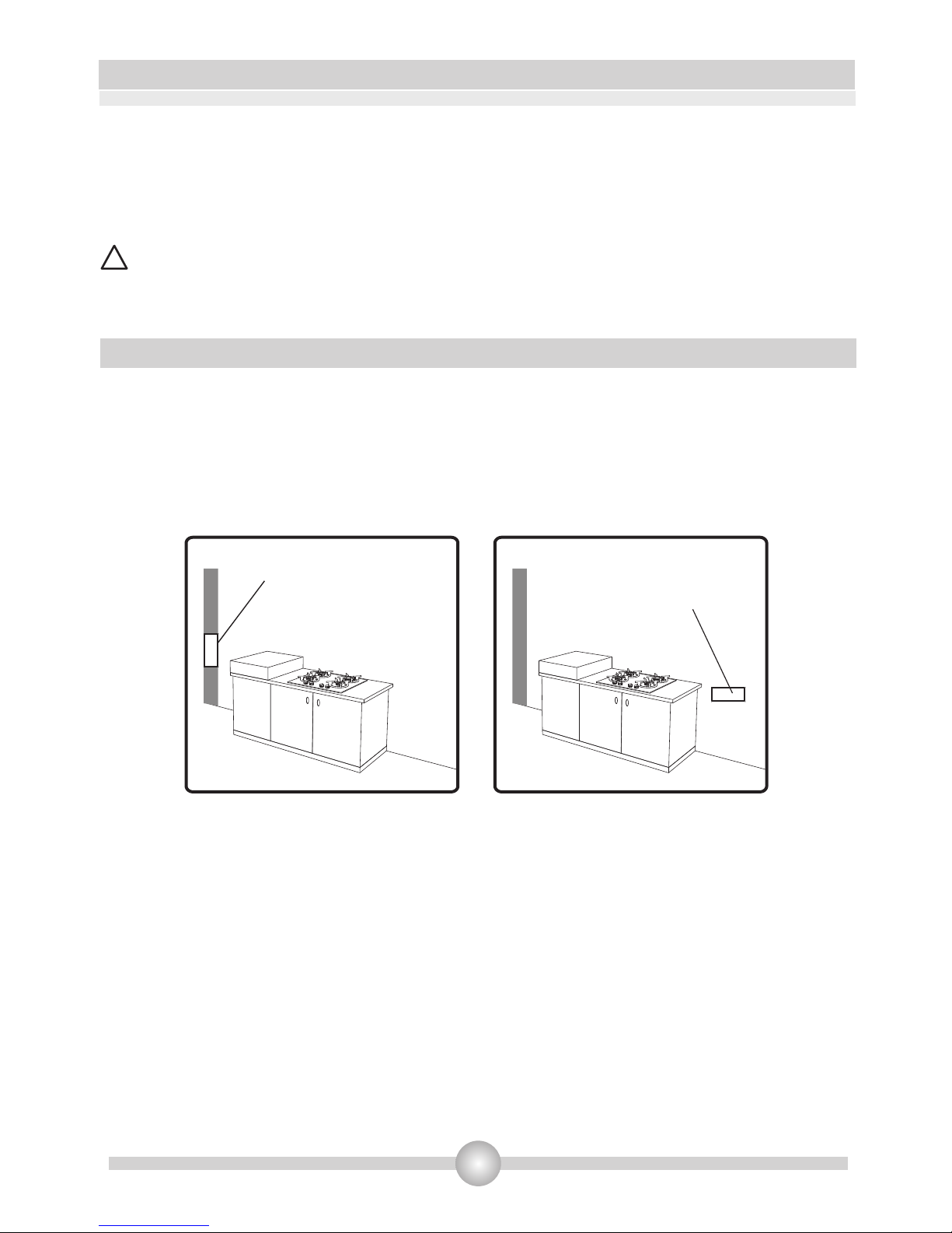
Your product must be set up and used in a place where it will always have ventilation
While operating, this appliance needs
There must be a natural ventilation enough to provide the gas to be used in the environment.
The average air flow must directly come in through the air holes that will be opened on the
walls that are opened towards outside.
.
Environment where your appliance will be installed 3.1.
• .
3
• 2m /h air per kw input.
•
!
• 2These air holes must have at least the effective cross section of 100cm for fresh air circulation
(One or more air holes can be opened.). This hole (or holes) must be opened so that they
shouldn't be blocked. Preferably they must be placed close to the bottom and at opposite side of
the smokes of the burned gases that were emptied. If it seems not possible to open these
ventilations in the place where the appliance is set up, the needed air can also be obtained
through the next room, provided that this place is not a bedroom or a dangerous place. In this
case this “next room” must also be ventilated as required.
Emptying of the Burned Gases from Environment
The cooking appliances that operate with gas, throw the burned gas wastes out directly to the
outside or through the cooker hoods that are connected to the a chimney that opens directly to the
outside. If it seems not possible to install a cooker hood, it is required to set an electric fan on the
window or wall that has access to fresh air. This electric fan must have the capacity to change the air
of the kitchen environment 4-5 times of its own volume of air per hour.
Figure 1
Air inlet section
2
min. 100cm
Figure 2
Air inlet section
2
min. 100cm
Page 9
8
INSTALLATION AND PREPARATIONS FOR USE
3.2 Installation of product
•
.
•
.
• .
• 100°C.
•
There are some factors that must be paid attention to while installing your product. Surely be very
careful to while installing your product. Pay attention to our below instructions in order to be able
to prevent any problems and/or dangerous situations that may occur later
The appliance can be placed close to other furniture on condition that in the area where the
oven is set up, the furniture's height does not exceed the height of the cooker panel
Pay attention not to place it near the refrigerator, there must be no flammable or inflammable
materials such as curtain, waterproof cloth, etc. that will begin to burn quickly
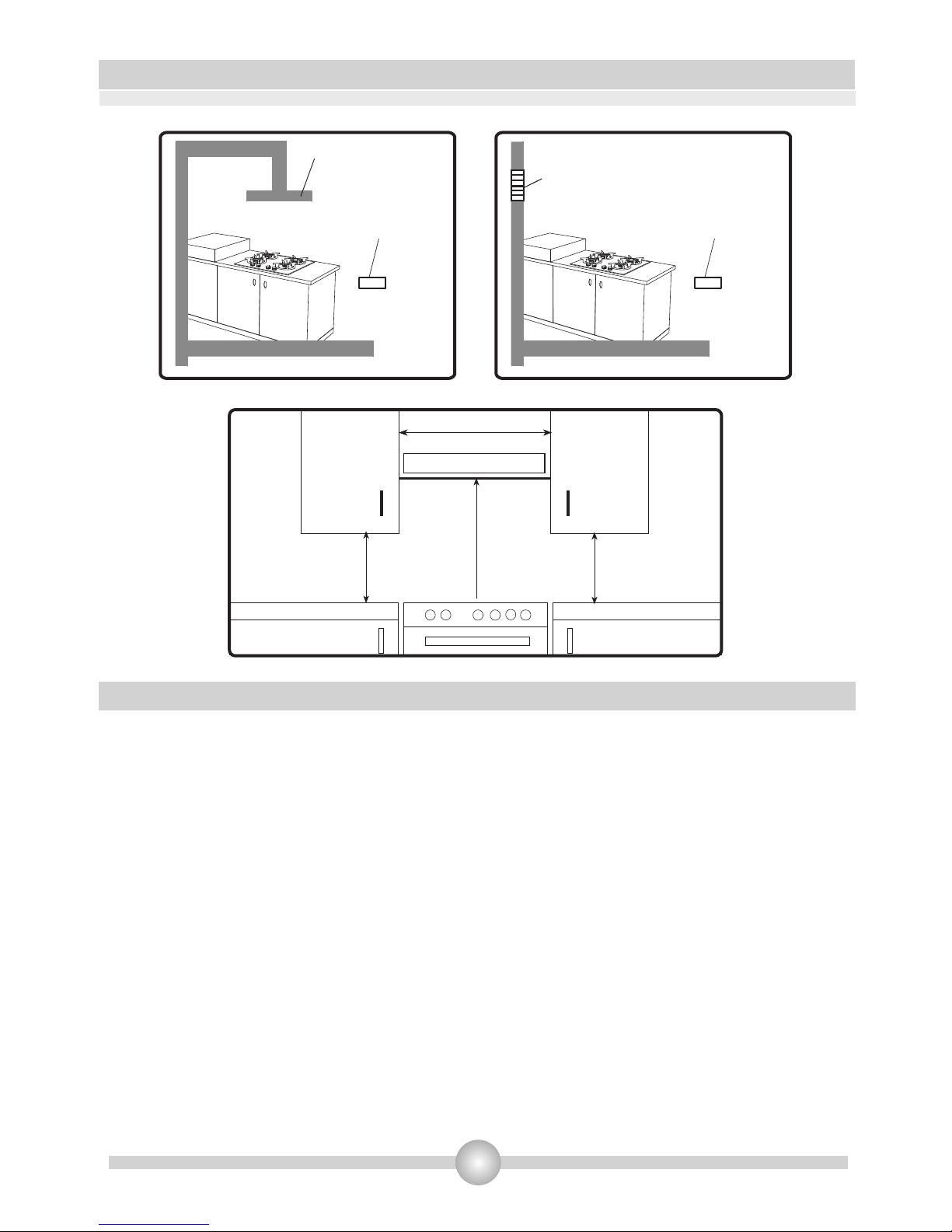
It is required that there must be least a 2cm blank space around the product for air circulation
The furniture close to product must be manufactured resistant to temperatures up to
If the kitchen furniture are higher than the cooktop, it must be at least 10cm away from the
cooker's side.
The minimum heights from the pan support and wall cupboards to cooker hoods with fan over the
product, are shown in figure 5. Thus, the cooker hood must be at minimum 65cm height from the
pan support. If there is no cooker hood, this height must not be less than 70cm.
.
Figure 5
Min. 60cm
COOKER HOOD
Min. 42cm
Min. 42cm
Min. 65cm(with hood)
Min. 70cm(without hood)
Air inlet section
2
min. 100cm
Cooker hood
flue
Air inlet section
2
min. 100cm
Figure 3 Figure 4
Electrical ventilator
Page 10
9
INSTALLATION AND PREPARATIONS FOR USE
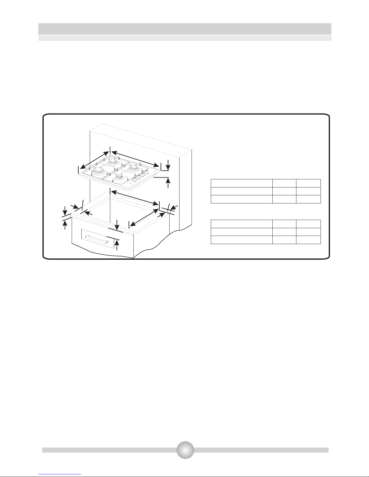
The appliance is supplied with an installation kit including adhesive sealing material and fixing
brackets&screws are included with the appliance.
• Cut the aperture dimensions as indicated in Figure - 1. Locate the aperture on the worktop such
that after the hob is installed the following reguirements are ensured;
Figure 6
510 mm
Min.
A
490 mm
Min.
B
Min.
100mm
Min.
25mm
580 mm
560 mm
42 mm
Neighbourhood walls
Combustible
Non-combustible
A[mm]
60
40
B[mm]
150
50
If your appliance have four hobs ;
Neighbourhood walls
Combustible
Non-combustible
A[mm]
60
40
B[mm]
150
100
If your appliance have five hobs ;
Page 11
•
the outher perimeter edge of the appliance. Ensure that the junctions overlap at the corners
and no gap is left along the sealing material.
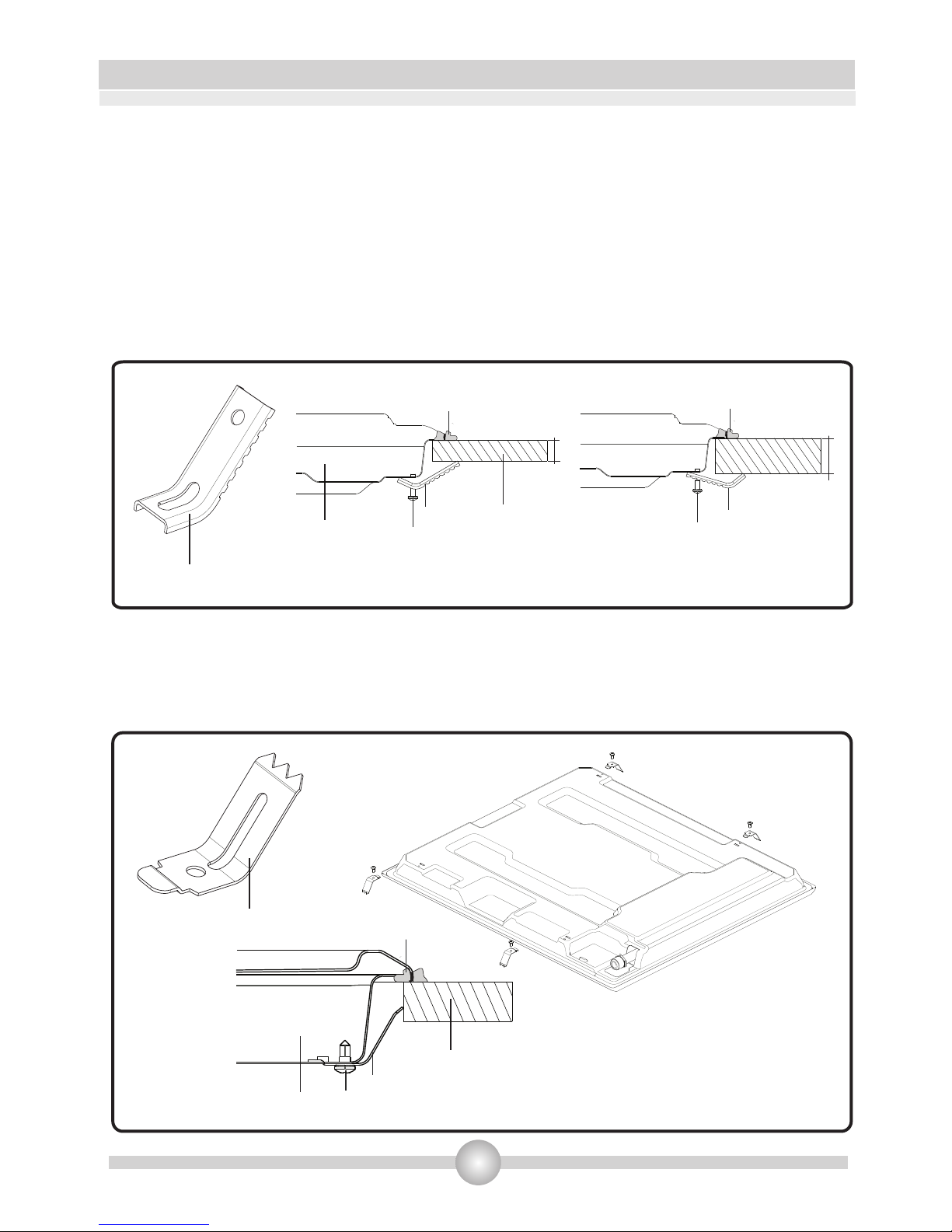
• Check the type of the brackets supplied in the assembly kit in Figure-7 and Figure-8 and
continue accordingly;
Brackets of Type-1
Insert the appliance into the aperture and fix in position via the brackets (A) and screws (B).
Adjust the position of the brackets depending on the thickness of the worktop as indicated in
Figure-7 and tighten the screws evenly.
Apply the adhesive sealing material “C” all the way round the aperture on the worktop to match
Brackets of Type-2
Fix the brackets (A) via the screws (B) on the bottom cover of the appliance as shown in Figure-8.
Insert the appliance into the aperture and apply pressure on the cooktop, ensure the appliance
is positioned tightly.
10
INSTALLATION AND PREPARATIONS FOR USE
Figure 7 - Installation with
Figure 8 - Installation with
Bracket Type 1
Bracket Type 2
Bracket Type 1
Tt
C
B
A
Hob
Worktop
t<25mm
B
A
Tt
C
B
A
t>25mm
Bracket Type 2
Hob
Worktop
C
Page 12

INSTALLATION AND PREPARATIONS FOR USE
11
3.3. Gas connection
The connection of the appliance should be performed in accordance with local and international
standards and regulations applicable. You can find the information related to appropriate gas types
and appropriate gas injectors on technical data table. If the pressure of used gas is different than
these values stated or not stable in your area, it may be required to assemble an available pressure
regulator on the gas inlet. It is certainly required to contact to the authorized service to make these
adjusments.
The points that must be checked during flexible hose assembly
If the gas connection is made by a flexible hose that is fixed on the gas inlet of appliance, it must be
fixed by a pipe collar as well. Connect your appliance with a short and durable hose that is as close
as possible to the gas source. The hose's permitted maximum lenght is 1.5m. The hose that brings
gas to the appliance must be changed once a year for your safety.
0
The hose must be kept clear from areas that may heat up to temperatures in excess of 90 C. The
hose must not be ruptured, bent or folded. It must be kept clear of sharp corners, moving things,
and should not be defective. Before assembly, it must be checked whether there is any production
defect.
As gas is turned on, all connection parts and hose must be checked with soapy water or leakage
fluids. Do not use naked flame to check gas leakage. All metal components used during gas
connection must be clear of rust. Also check the expiry dates of components to be used.
Assembly of gas supply and leakage check
The points that must be checked during fixed gas connection assembly
To assemble a fixed gas connection (gas connection made by threads, e.g. a nut), there are different
methods used in different countries. The most common parts are already supplied with your appliance.
Any other part can be supplied as spare part.
•
Important: If the appliance is to be installed above a cupboard or drawer it is absolutely
essential that you place a seperator between the base of the appliance and the drawer unit.
Carefully trim away the excess sealing material “C” from around the appliance.
!
Page 13
INSTALLATION AND PREPARATIONS FOR USE
12
During connections always keep the nut on the gas manifold fixed, while rotating the counter-part.
Use spanners of appropriate size for safe connection. For all surfaces between different
components, always use the seals provided in the gas conversion kit. The seals used during
connection should also be approved to be used in gas connections. Do not use plumbing seals for
gas connections.
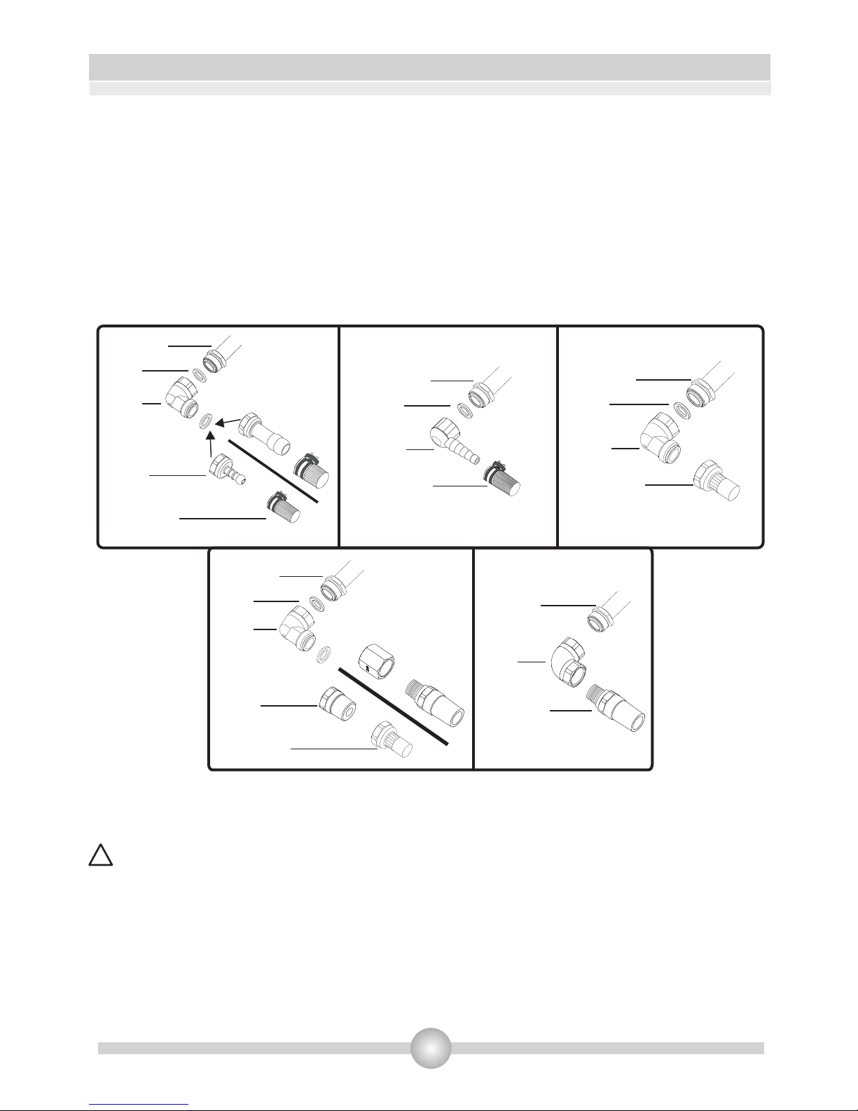
Remember that this appliance is ready to be connected to gas supply in the country for which it has
been produced. The main country of destination is marked on the rear cover of the appliance. If you
need to use it in another country, any of the connections in the figure below can be required.
In such a case, contact local authorities to learn the correct gas connection.
It is required to call the authorized service to be able to make the gas connections appropriately
and in compliance with safety standards.
ATTENTION! Surely do not use any match or lighter for control of gas leakage.
!
Seal
Hose
Fitting
Hose
Fitting
Gas Hose
with Collar
Gas Pipe
Figure 9
Seal
Hose
Fitting
Gas Hose
with Collar
Gas Pipe
Mechanical
Gas Hose
Seal
Hose
Fitting
Gas Pipe
Seal
Hose
Fitting
Hose
Fitting
Mechanical
Gas Hose
Gas Pipe
Mechanical
Gas Hose
Hose
Fitting
Gas Pipe
Page 14
INSTALLATION AND PREPARATIONS FOR USE
13
3.4 Gas conversion
:
Changing injectors:
• .
•
•
•
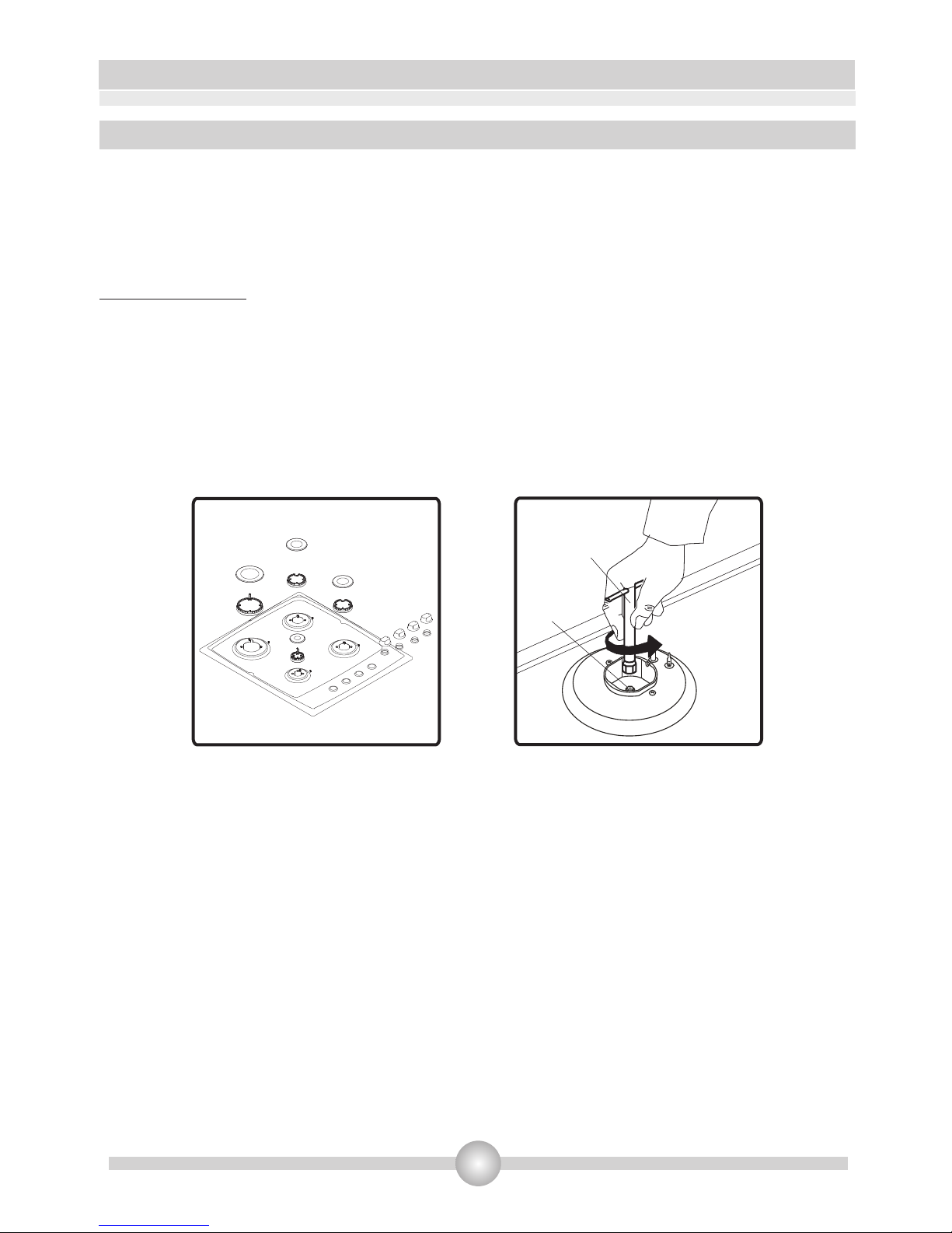
Caution: The following procedures must be undertaken by authorized service people.
Your appliance is adjusted to be operated with LPG/NG gas. The gas burners can be adapted to
different types of gas, by replacing the corresponding injectors and adjusting minimum flame length
suitable to the gas in use. For this purpose, following steps should be performed
Cut off the main gas supply and unplug from the electric mains
Remove the burner cap and the adapter(Figure 10).
Unscrew the injectors. For this, use a 7mm spanner(Figure 11).
Replace the injector with the ones from the gas conversion kit, with corresponding diameters
suitable to the type of gas that is going to be used, according to the information chart (which is
also supplied in the gas conversion kit).
Figure 11
Injector
Spanner
Figure 10
Adjusting the reduced flame position
The flame length in the minimum position is adjusted with a flat screw located on the valve. For
valves with flame failure device, the screw is located on the side of the valve spindle(Figure 8-9). For
valves without flame failure device, the screw is located inside the valve spindle(Figure 10). For
easier reduced flame adjustment, it is advised to remove the control panel (and microswitch, if
present) during adjustment.
To determine the minimum position, ignite the burners and leave them on in minimum position.
Remove the with the help of a small screwdriver fasten or loosen the bypass screw around 90
angular degrees. When the flame has a length of at least 4mm, the gas is well distributed. Make
sure that the flame does not die out when passing from the maximum position to the minimum
position. Create an artificial wind with your hand toward the flame to see if the flames are stable.
:
Page 15

INSTALLATION AND PREPARATIONS FOR USE
14
Changing the gas inlet:
For some countries, the gas inlet type can be different for NG/LPG gases. In such a case, remove the
current connection components and nuts (if any) and connect the new gas supply accordingly. In all
conditions, all components used in gas connections should be approved by local and/or
international authorities. In all gas connections, refer to the “Assembly of gas supply and leakage
check” clause explained before.
Figure 13
Figure 14
Figure 12
Valve with flame failure device Valve with flame failure device Valve without flame failure device
Bypass screw
Bypass screw
Bypass screw
(Inside the hole)
The position the bypass screw must be loosened for conversion from LPG to NG. For conversion
from NG to LPG, the same screw must be fastened. Make sure that the appliance is unpluged from
the electric mains and the gas supply is open.
Page 16
· Before proceeding with the electrical connection, verify that the current carrying capacity of
the system and the socket is adequate for the maximum power rating of the hob.
· Electrical installation of the residence and the electrical current plug in use must be earthed
and conform with safety regulations.
· If there is no dedicated hob circuit and fused switch, they must be installed by a qualified
electrician before the hob is connected.
. Fused switch must be easily accessible once the hob has been installed.
· Do not use adaptors, multiple sockets and/or extension leads.
· This appliance conforms with the requirements ofthe following EEC Directives:
1. Vitroceramic hob EEC/73/23 and 93/68, EEC/89/336 relating to radio interference,
2. EEC/89/109 relating to contact with foods.
· A circuit breaker with a contact opening of at least 3mm must be installed inside the supply
circuit.
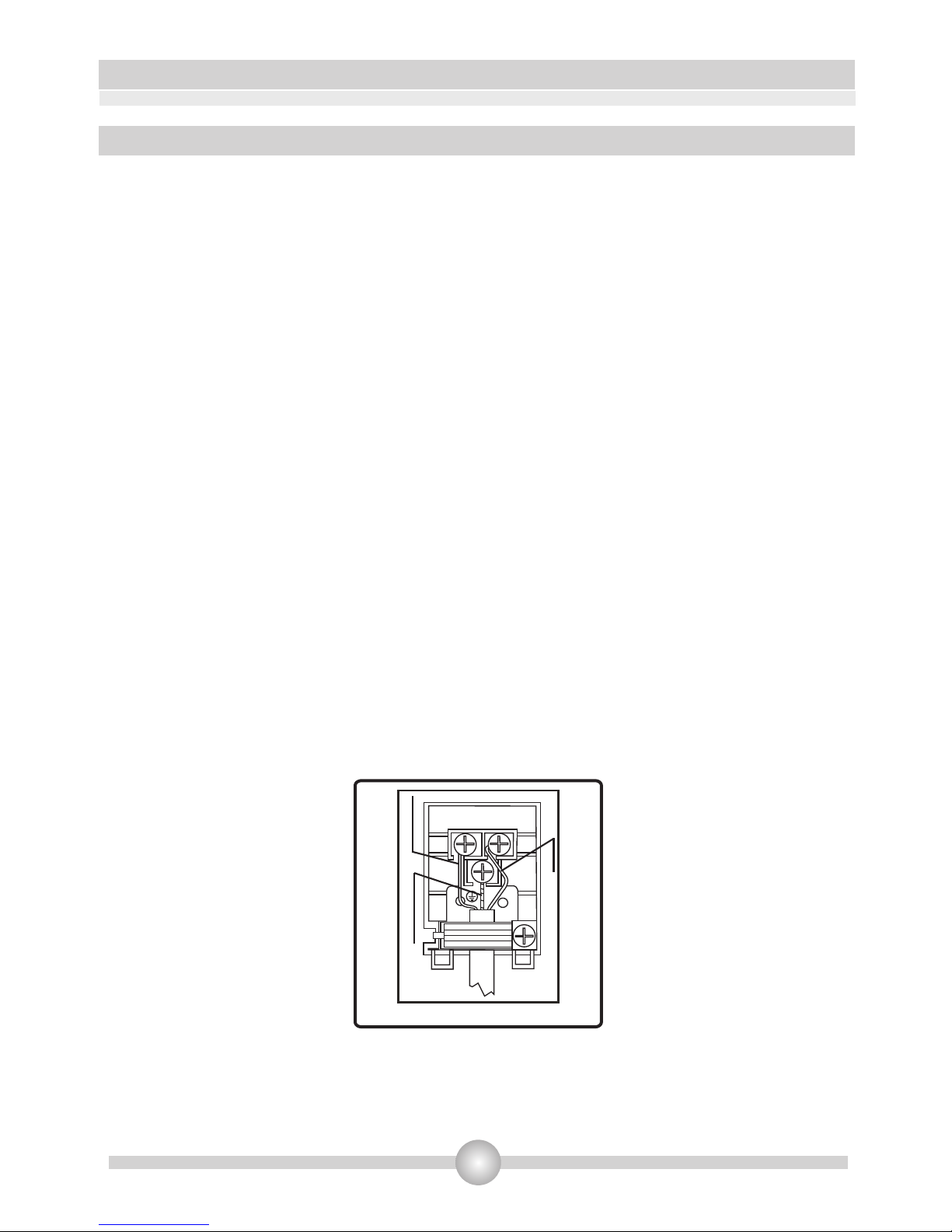
· For the knob controlled vitroceramic hob with two heating elements, the cable must be
H05VV-F 3X1,5mm². For the knob controlled vitroceramic hob with one heating elements, the
cable must be H05VV-F 3X1,0mm². You will find the connection diagram shown on the bottom
of your appliance.
INSTALLATION AND PREPARATIONS FOR USE
15
Figure 15
L
N
BROWN
YELLOW+GREEN
BLUE
3.5 Electrical Connection Of Your Hob
Page 17

4. USE OF YOUR PRODUCT
16
4.1 Use of gas burners
•
:
•
.
Flame safety device:
.
Ignition of the burners
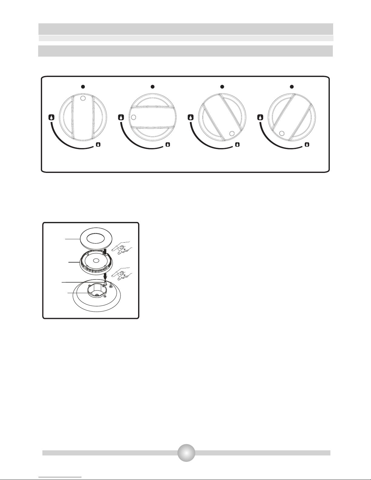
To determine which knob controls which burner, check the position symbol above the knob.
Manual Ignition
If your appliance is not equipped with any ignition aid or in case there is a failure in the electric
network, follow the procedures listed below
To ignite one of the burners, press and turn its knob counter-clockwise so that the knob is in
maximum position, approach a match, taper or another manual aid to its upper circumference.
Move the ignition source away as soon as you see a stable flame.
Electrical Ignition
Electrical ignition of gas burners can be performed in two ways; depending on the configuration of
your appliance
Ignition by Hob Control Knob: Press the hob control knob of the burner you want to operate and
turn the hob control knob in the counterclockwise direction so that the knob is in maximum
position while keeping the knob pressed. The spark plugs will generate sparks as long as you keep
the control knob pressed. The micro switch placed under the knob will automatically create sparks
through the spark plug of the burner. Continue pressing the knob until you see a stable flame on
the burner.
Hob Burners (If your hob is equipped with gas safety device)
Hobs equipped with flame failure device provide security in case of accidentally extinguished flame.
If such a case occurs, the device will block the burners gas lines and will avoid any accumulation of
unburned gas. Wait 90 seconds before re-igniting an extinguished gas burner
Ignition by Spark Button: Press the valve of the burner you want to
operate and turn the valve in the counter-clockwise direction so that the
knob is in maximum position and with your other hand, press the ignition
button (Figure 16) at the same time. Press the ignition button
immediately, because if you wait, a build up of gas may cause the flame to
spread. Continue pressing the ignition button until you see a stable flame
on the burner.
Figure 16
Page 18
USE OF YOUR PRODUCT
17
Control of the hob burners
The knob has 3 positions: Off (0), maximum (big flame symbol) and minimum (small flame symbol).
After you ignite the burner in maximum position; you can adjust the flame length between
maximum and min. positions. Do not operate the burners when the knob position is between
maximum and off positions.
After the ignition, check the flames visually. If you see yellow
tip, lifted or unstable flames; turn the gas flow off, and check
the assembly of burner caps and crowns (Figure 18). Also,
make sure that no liquid has flown into the burner cups. If
the burner flame goes out accidentally, turn the burner off,
ventilate the kitchen with fresh air, and do not attempt reignition for 90 sec.
When turning the hob off, turn the knob in the clockwise
direction so that the knob shows "0" position or the marker
on the knob points upwards.
Your hob has burners of different diameters. The most economic way of using gas is to choose the
correct size gas burners for your cooking pan size and to bring the flame to minimum position once
the boiling point is reached. It is recommended to always cover your cooking pan.
In order to obtain maximum performance from the main burners, use pots with the following flat
bottom diameters. Using smaller pots than the minimum dimensions stated below will cause
energy loss.
Rapid / Wok Burner: 22-26cm
Semi-rapid Burner: 14-22cm
Auxiliary Burner: 12-18cm
MAX. position
OFF position
Figure 17
MODULATE
MIN. position
Figure 18
Cap
Crown
Spark
Plug
Burner
Cup
4.2 Control of the hob burners
Page 19

USE OF YOUR PRODUCT
18
Make sure that the tips of the flames do not spread out of the outer circumference of the pan, as
this may also harm the plastic accessories around the pan (handles etc.)
When the burners are not in use for prolonged periods, always turn the main gas control valve off.
Do not use cooking containers that protrude from the cookers' table andwhich are likely to
overheat the control levers
.
Warning:
• Use only flat pans and with a sufficiently thick base.
• Ensure that the base of the pan is dry before placing it on the burners.
• The temperature of accessible parts may be high when the appliance is operating. So it is
imperative to keep children and animals out of the reach of the burners during and after
cooking.
• After use, the hob remains very hot for a prolonged period of time, do not touch it and do not
place any object on top of the hob.
• Never place knives, forks, spoons and lids on the hob as they will get hot and could cause
serious burns.
•
!
Figure 19
Page 20

4.3. Control of the electric hobs
USE OF YOUR PRODUCT
19
The appliance is operated by using knob control and the heat stored is confirmed by residual heat indicator
lamp on the vitroceramic surface.
Knob controlled cooker is designed for operating at 6 heat levels:
1 Keeping warm position
2-3 Heating position at low heat
4-5-6 Cooking – roasting and boiling position
Dual heaters have two heating zones. To activate the outer zone of a dual heater, turn the knob to
position once. In this way both outer zones switches on.
To deactivate the outer zone of a dual heater, turn the knob to position once. In this way, both outer
zones switches off.
Residual Heat Functions
After all cooking processes there is some heat stored in the vitroceramic glass called residual heat. The
control can calculate roughly how hot the glass is in the worst case. If the calculated temperature is higher
than + 60 °C, then this will be indicated in the related residual heat indicator lamp. The residual heat
display is shown as long as the calculated heater temperature is > + 60 °C.
After reapplying the supply voltage to the hob control after an interruption of the supply voltage occurred,
causes that the residual heat display flashes, if the corresponding heater had a residual heat of greater +
60 ° C before the power interruption occurred. The display will flash until the max. residual heat time has
expired or the heater will be selected and activated.
Page 21

Warning:
When the operating for the first time or whenever the hotplate has not been used for a prolonged
time it is necessary to eliminate any humidity which may have accumulated around the electrical
elements of the plate by operating the hotplate on its lowest setting for about 20 minutes.
Use only flat pans and with a sufficiently thick base.
Never use a pan with a smaller diameter than of the hotplate.
Ensure that the base of the pan is dry before placing it on the hotplate. While the hotplate is in
operation, it is important to ensure that the pan is centered correctly above the hotplate.
•
•
•
20
USE OF YOUR PRODUCT
!
CORRECT
INCORRECT
circular saucepan base
INCORRECT
saucepan’s base had not settled
INCORRECT
small saucepan diameter
Figure 20
• Never operate the hob without pans on the hotplate.
• The temperature of accessible parts maybe high when the appliance is operating. So it is
imperative to keep children and animals out of the reach of the hotplate during and after the
operation.
• If you note a crack on the hotplate it must be immediately switched off and replaced.
Page 22

USE OF YOUR PRODUCT
21
Place coffee adaptor on the Auxiliary burner grid when small
cookware is used to prevent the cookware from tipping over.
Coffee Adaptor (Optional)
Wok adaptor should be placed on the pan support of wok burner.
WARNING: Using wok pans without wok adaptor may cause the burner
to malfunction.
Please do not use wok adaptor with flat-bottomed saucepans. Likewise,
do not use convex-bottomed saucepans without the wok adaptor.
Wok Adaptor (Optional)
CORRECT
INCORRECT
• To ensure long life, the hotplate must be thoroughly cleaned with appropriate cleaning
products. To avoid rustiness and to keep them new it is recommended to rub the hotplate
lightly with tissue with a small amount of oil. Do not use a steam cleaner.
• After use, the hotplate remain very hot for a prolonged of time, do not touch them and to not
place any object on top of the hotplate.
4.4 Accesorries
• The product already supplied with accessories. You can also use accessories you purchase from
the market, but they must be heat and flame resistant. You can also use glass dishes, cake
molds, special oven trays that are appropriate for use in oven. Pay attention to the using
instructions by the manufacturer of those acessories.
Page 23

22
5. CLEANING AND MAINTENANCE
5.1 Cleaning
Be sure that all control switches are off and your appliance cooled before cleaning your oven. Plug
off the appliance. Check whether they are appropriate and recommended by the manufacturer
before using the cleaning materials on your oven. As they may damage the surfaces, do not use
caustic creams, abrasive cleaning powders, thick wire wool or hard tools. In case the liquids that
overflow around your oven burn, the enameled parts may be damaged. Immediately clean the
overflown liquids.
Cleaning of Your Hob
• Lift up the pan supports, caps and crowns of hob burners.
• Wipe and clean the back panel with a soapy cloth.
• Wash the caps and crowns of hob burners and rinse them. Do not leave them wet, immediately
dry them with paper cloth.
• After cleaning, make sure that you re-assemble the parts correctly.
• Do not clean any part of the hob with metal sponge. It causes the surface be scratched.
• The pan support top surfaces may be scratched in time due to usage. In this case,these parts
may get rusted and it is not a production fault.
• During cleaning of the hob plate, make sure that no water flows inside the burner caps, as this
may block the injectors.
Burner Caps:
Periodically, enameled pan support, enameled covers, burner heads must be washed with soapy
warm water rinsed and dried. After drying them thoroughly, replace them correctly.
Enamelled Parts:
In order to keep them a new, it is necessary to clean them frequently with mild warm soapy water
and then dry with cloth. Do not wash them while hot and never use abrasive powders or abrasive
cleaning materials. Do not leave vinegar, coffee, milk, salt, water, lemon, or tomato juice to remain
in contact with enameled parts for long periods of time.
Stainless Steel:
Stainless steel parts must be cleaned frequently with mildly warm soapy water and a soft sponge
and then dry with a soft cloth. Do not use abrasive powders or abrasive cleaning metarials. Do not
leave vinegar, coffee, milk, salt, water, lemon or tomato juice to remain in contact with stainless
steel parts long periods of time.
Page 24

Cleaning hotplates:
Clean the hotplates with a damp sponge and then dry them by turning them on for a few seconds.
To maintain their appearance, apply a small amount of oil on the surface of hotplates.
The hotplate trim rings can be cleaned with products intended for stainless steel. The rings can
become yellowed as a result of heating. This is normal.
If a hotplate is to be out of use for a long time, apply the special grease periodically.
5.2 Maintenance
Periodically check the gas connection pipe. Even if any simple abnormality is felt, inform the
technical service to have it changed. We recommend the gas connection parts to be changed once
a year. If any abnormality is felt while operating the control knobs of cooker, contact to the
authorized service.
23
CLEANING AND MAINTENANCE
Page 25

6.1 Basic troubleshooting before contacting service
If the electrical ignition/hotplate does not operate :
• The hob may be plugged off, there has been a black out.
If the hotplate does not heat :
• The heat may be not adjusted correctly with hob heater control switch.
The hob burners do not operate correctly :
• Check if the burner parts are correctly assembled(especially after cleaning).
• The gas supply pressure may be too low/high. For appliances working with bottled LPG, the
LPG cylinder may be depleted.
Except these, if you still have any problem with your product, please call to the Authorized
Service.
6.2 Information related to transport
If you need any transport; keep the original case of product and carry it with its original case when
needed to be carried. Follow the transport signs on packaging. Tape the hob on upper parts, caps
and crowns and pan supports to the cooking panels.
If you do not have the original packaging; prepeare a carriage box so that the appliance, especially
external surfaces (glass and painted surfaces) of oven is protected against external threats.
24
6. SERVICE AND TRANSPORT
Page 26

Table
G30 28-30mbar 4,8 kW 345g/h
II2H3+ GB Classe 3
LPG
G30 28-30 mbar
NG
G20 20 mbar
LARGE BURNER
DIA. of INJECTOR (1/100mm) 85 115
NOMINAL RATING (KW) 3 3
CONSUMPTION 218,1 g/h 285,7 l/h
MEDIUM BURNER
DIA. of INJECTOR (1/100mm) 65 97
NOMINAL RATING (KW) 1,75 1,75
CONSUMPTION 127,2 g/h 166,7 l/h
25
FR
Page 27

The symbol on the product or on its packaging indicates that this product
may not be treated as household waste. Instead it shall be handed over to
the applicable collection point for the recycling of electrical and electronic
equipment. By ensuring this product is disposed of correctly, you will help
prevent potential negative consequences for the environment and human
health, which could otherwise be caused by inappropriate waste handling of
this product. For more detailed information about recyling of this product,
please contact your local city office, your household waste disposal service or
the shop where you purchased the product.
Page 28

INSTRUCTIONS DE FONCTIONNEMENT
ET D'INSTALLATION DU PLAN DE
CUISSON ENCASTRABLE
FR
OCEACPM2G2V
Page 29

Chère cliente, cher client,
Notre objectif est de vous offrir des produits de qualité supérieure qui vont au-delà
de vos attentes. C'est pourquoi nous les fabriquons dans des infrastructures
modernes soigneusement et particulièrement testées pour leur qualité.
Ce manuel contient toutes les informations nécessaires à l'utilisation de cet appareil
conçu avec une technologie de pointe, en toute confiance et efficacité.
Avant de commencer à utiliser votre appareil, nous vous suggérons de lire ce guide
qui contient tous les renseignements de base pour une installation correcte et fiable,
l'entretien l'utilisation du produit. Veuillez contacter le service agrée le plus proche
pour procéder à l'installation de votre appareil.
Déclaration de conformité CE
Cet appareil a été conçu pour être utilisé uniquement à des fins de cuisson
domestique. Toute autre forme d'utilisation (le chauffage d'une pièce par exemple)
est inappropriée et dangereuse.
Cet appareil a été conçu, construit, et commercialisé conformément aux :
Consignes de sécurité de la directive 2009/142/CE portant sur le « gaz » ;
Consignes de sécurité de la directive 2006/95/CE portant sur la « basse tension »;
Consignes de sécurité de la directive 2004/108/CE portant sur l' « EMC » ;
Consignes relatives à la directive 93/68/CE.
•
•
•
•
Page 30

1
Remarque: Tous les chiffres figurant dans le manuel sont illustratifs.
TABLE DES MATIÈRES
1. BRÈVE PRÉSENTATION DU PRODUIT
2. AVERTISSEMENTS
3. INSTALLATION ET PRÉPARATION À L'UTILISATION
3.4 Conversions des gaz
4. UTILISATION DE VOTRE FOUR
4.1: Utilisation des brûleurs
4.2
4.3
5. NETTOYAGE ET ENTRETIEN
5.1 : Nettoyage
5.2: Entretien
6. SERVICE APRES-VENTE ET TRANSPORT
6.2:Informations relatives au transport
3.1:Environnement d'installation de l'appareil
3.2: Installation de l'appareil
3.3 Raccordement au gaz
3.5 Branchement électrique de votre table de cuisson
Commande des brûleurs de la table de cuisson
Commande des brûleurs des plaques électriques
6.1:Dépannage de base à effectuer avant de contacter le service Clients
4.4 Accessoires
Page 31

1.BRÈVE PRÉSENTATION DU PRODUIT
* Votre plaque peut être différente du modèle présenté ci-dessus à cause de
sa configuration.
1 -
2 Brûleur semi-rapide
3- Brûleur auxiliaire
4 Brûleur rapide
5-boutons de commande
6 - Chauffage électrique (180 mm)
7 Plan de travail
8-Plateau de support
9-Chauffage électrique (Double 180 mm)
Chauffage électrique (145 mm)
1 4
7
6
3
5
8
2
7
5
3
4
8
9
7
5
2
3
4
6
8
2
Page 32

AVERTISSEMENTS EN MATIÈRE DE SÉCURITÉ
LISEZ ATTENTIVEMENT ET ENTIEREMENT CETTE NOTICE AVANT D’UTILISER VOTRE APPAREIL DE
CUISSON, ET CONSERVEZ-LA AFIN DE POUVOIR LA CONSULTER LORSQUE CE SERA NECESSAIRE.
Cette notice est conçue pour plusieurs modèles. Votre appareil de cuisson n’est peut-être pas
équipé de toutes les caractéristiques décrites dans cette notice. Veuillez contrôler dans la notice
les caractéristiques dans les paragraphes comportant des images.
Consignes de sécurité générales:
• La fabrication de votre appareil de cuisson respecte toutes les normes et réglementations
nationales et internationales en vigueur en la matière.
• Les travaux de maintenance et d'entretien doivent être effectués exclusivement par des
techniciens qualifiés. Les travaux de réparation et d'entretien effectués par des personnes nonqualifiées vous exposent à des dangers. Il est fortement déconseillé de modifier les spécifications
de votre appareil de cuisson de quelque manière que ce soit. Evitez d'effectuer vous-mêmes les
réparations au risque d’être victime d’une électrocution.
• Avant l'installation, assurez-vous que les conditions de distribution locale (nature et pression du
gaz, tension et fréquence de l'électricité) sont compatibles avec les caractéristiques indiquées sur
la plaque signalétique de votre appareil de cuisson. En cas de dommage provoqué par un
branchement ou une installation inadaptée, la garantie ne sera pas valide.
• La sécurité électrique de votre appareil de cuisson n'est garantie que s'il est branché à une
alimentation électrique avec terre, conforme aux normes de sécurité électrique en vigueur. Si vous
n’êtes pas sûr de votre installation électrique avec terre, consultez un électricien qualifié.
• ATTENTION: Votre appareil de cuisson est conçu uniquement pour la cuisson des aliments et il
est prévu uniquement pour un usage domestique. Il ne doit absolument pas être utilisé à d'autres
fins, par exemple, dans un environnement commercial ou pour le réchauffage d'une salle. La
responsabilité du fabricant ne saurait être engagée en cas de dommages liés à une utilisation
inappropriée, incorrecte, ou négligente
• Cet appareil de cuisson ne doit pas être utilisé par des
enfants de moins de 8 ans, ou par des personnes dont les
capacités physiques, sensorielles ou mentales sont
limitées, ou manquant d’expérience ou de connaissances
requises, les empêchant d’utiliser cet appareil de cuisson
sans risque lorsqu’ils sont sans surveillance ou en l’absence
d’instructions d’une personne responsable leur assurant
une utilisation de l'appareil de cuisson sans danger, après
une explication des risques auxquels ils s'exposent. Les
enfants ne doivent pas jouer avec l'appareil de cuisson. Les
3
2.CONSIGNES DE SÉCURITÉ
Page 33

4
AVERTISSEMENTS EN MATIÈRE DE SÉCURITÉ
opérations de nettoyage et d'entretien effectués par des
enfants doivent se faire sous la supervision d'une personne
responsable.
• Cet appareil de cuisson n'est pas connecté à un dispositif de d'évacuation des produits de la
combustion. Il doit être installé et raccordé conformément aux règles d'installation en vigueur. Une
attention particulière doit être accordée aux exigences concernant la ventilation.
• Si au bout de 15 secondes le brûleur gaz ne s'est pas allumé, fermez la manette du brûleur
concerné, ouvrez la porte de la cuisine et attendez au moins une minute avant d'essayer de le
rallumer à nouveau.
• Ces instructions ne sont valides que si le symbole du pays est sur votre appareil de cuisson. Si le
symbole du pays n’est pas sur votre appareil de cuisson, il importe de se référer aux instructions
techniques fournissant les informations nécessaires relatives aux conditions d'utilisation
particulières
MISE EN GARDE : L’appareil et ses parties accessibles
peuvent devenir très chauds durant l’utilisation. Attention à
ne pas toucher les éléments chauffants. Les enfants de
moins de 8 ans doivent être maintenus à l’écart sauf s’ils
sont constamment supervisés. AVERTISSEMENT: Pendant
l'utilisation, tous les éléments accessibles de votre appareil
de cuisson deviennent chauds, et gardent pendant un
certain temps leur température élevée, même quand
l'appareil de cuisson est arrêté. Ne touchez pas les surfaces
chaudes (manettes et poignée du four comprise) et
empêchez les enfants de moins de 8 ans d’approcher de
l'appareil de cuisson. Il est recommandé de laisser refroidir
les parties directement exposées à la chaleur avant de les
toucher.
AVERTISSEMENT: Ne laissez pas votre appareil de cuisson
sans surveillance lorsque vous faites cuire des matières
grasses liquides ou solides, des huiles liquides ou solides.
Portées à très haute température, ces matières peuvent
Page 34

5
AVERTISSEMENTS EN MATIÈRE DE SÉCURITÉ
prendre feu et engendrer un incendie. N'ESSAYEZ jamais
d'éteindre avec de l'eau des flammes provenant d’huile en
feu, mais éteignez votre appareil de cuisson et couvrez la
casserole ou la poêle avec un couvercle, afin d’étouffer la
flamme. Si vous avez une hotte, ne jamais la mettre en
route sans surveillance quand vous faites chauffer de
l’huile. Ne laissez pas de matière inflammable près de votre
appareil de cuisson lorsqu’il fonctionne.
MISE EN GARDE: Danger de feu: Ne jamais placer d'objets
sur la plaque de cuisson. AVERTISSEMENT: Risque
d'incendie: Ne rangez pas d'objets sur les surfaces de
cuisson et ne rangez aucun contenant pressurisé tel que les
aérosols, les matériaux inflammables (objets en papier, en
plastique et en tissu), dans le tiroir placé sous le four ou
sous la plaque de cuisson. Les ustensiles de cuisine en
plastique en font également partie (ainsi que les manches
d’ustensiles).
MISE EN GARDE: Si la surface est fêlée, déconnecter
l'appareil de l'alimentation
pour éviter un risque de choc électrique. AVERTISSEMENT:
Si votre appareil de cuisson est équipé d'un plan de cuisson
en verre (vitro ou induction) et si la surface est fissurée,
mettez les manettes sur "0" pour éviter un éventuel choc
électrique. De même, si des fissures apparaissent sur les
plaques électriques, il est impératif d’arrêter
immédiatement l’alimentation électrique afin de prévenir
toute électrocution.
Page 35

AVERTISSEMENTS EN MATIÈRE DE SÉCURITÉ
6
Il convient d'enlever du couvercle tout résidu de
débordement avant de l'ouvrir. Si votre appareil de cuisson
est équipé d'un couvercle, ce couvercle doit être soulevé
avant la mise en fonction des zones de cuisson. Avant de
refermer le couvercle, il faut s'assurer que l'appareil de
cuisson a bien refroidi. Les couvercles en verre peuvent se
casser lorsqu'ils sont chauffés. Éteignez tous les brûleurs
avant de fermer le couvercle.
Cet appareil n'est pas destiné à être mis en
fonctionnement au moyen d'une minuterie extérieure ou
par un système de commande à distance séparé. Votre
appareil de cuisson ne doit jamais être branché sur une
rallonge, sur une minuterie extérieure, une prise triplite ou
un système de commande à distance séparée ou tout
autre dispositif qui mettrait l'appareil sous tension
automatiquement.
• N'utilisez pas des produits de nettoyage abrasifs, des
crèmes caustiques, des éponges abrasives ou des grattoirs
métalliques pour nettoyer tous les éléments de votre
appareil de cuisson (verre, émail, inox, plastique et
peinture), car cela raierait les surfaces, et pourrait
entraîner l'éclatement des surfaces en verre ou la
destruction des autres éléments de votre appareil de
cuisson. Ne pas utiliser de produits d'entretien abrasifs ou
de grattoirs métalliques durs pour nettoyer
la porte en verre du four, ce qui pourrait érafler la surface
et entraîner l’éclatement du verre.
Page 36

• N'utilisez pas de nettoyeurs à vapeur pour nettoyer votre
appareil de cuisson.
• Toutes les mesures de sécurité possibles ont été prises pour garantir votre sécurité. Pour éviter de
casser les éléments en verre, vous devez faire attention de ne pas les rayer pendant le nettoyage.
Evitez aussi de taper ces surfaces en verre ou de laisser tomber des accessoires dessus, et de
monter sur le verre (dans le cas d’un travail au-dessus de votre appareil de cuisson).
• Ne faites aucune pression sur le fil électrique (si équipé) lors de l'installation de votre appareil de
cuisson. Assurez-vous aussi que la câble n’est pas coincé derrière votre appareil de cuisson. Si le
câble d'alimentation est endommagé, il doit être remplacé par un câble présentant les mêmes
caractéristiques que celui d’origine, et ceci par un technicien qualifié afin d'écarter tout danger.
Avertissements d'installation:
• N'utilisez votre appareil de cuisson que lorsque l'installation est terminée.
• Votre appareil de cuisson doit être installé et mis en service par un technicien qualifié. Le
fabricant décline sa responsabilité pour tout dommage résultant d'un mauvais emplacement ou de
l'installation de votre appareil de cuisson par un technicien non qualifié.
• Après avoir déballé votre appareil de cuisson, vérifiez soigneusement si celui-ci n'a pas été
endommagé pendant le transport. En cas de dommage, ne l’utilisez pas et contactez
immédiatement votre Revendeur. Etant donné que les matériaux d’emballage (polystyrène, nylon,
agrafes, etc...) peuvent être dangereux pour les enfants, veuillez les rassembler et les éliminer
immédiatement (mettez-les dans les conteneurs spécifiques pour le recyclage)
• Protégez votre appareil de cuisson contre les effets atmosphériques. Ne l'exposez pas au soleil, à
la pluie, la neige, la poudre, etc.
• Les matériaux entourant l'appareil (meubles) doivent être capables de supporter une
température minimale de 100°C.
Lors de l'utilisation:
• Ne placez pas de matériaux inflammables ou combustibles à proximité de votre appareil de
cuisson pendant son fonctionnement.
• Ne laissez pas votre appareil de cuisson sans surveillance lorsque vous faites cuire des matières
grasses liquides ou solides, des huiles liquides ou solides. Portées à très haute température, ces
matières peuvent prendre feu et engendrer un incendie. N'ESSAYEZ jamais d'éteindre avec de l'eau
des flammes provenant d’huile en feu, mais éteignez votre appareil de cuisson et couvrez la
casserole ou la poêle avec un couvercle, afin d’étouffer la flamme. Si vous avez une hotte, ne jamais
la mettre en route sans surveillance quand vous faites chauffer de l’huile. Ne laissez pas de matière
inflammable près de votre appareil de cuisson lorsqu’il fonctionne.
• Toujours poser les ustensiles de cuisson au centre de la zone de cuisson et positionner les
poignées de telle sorte qu'elles ne puissent pas gêner ou être attrapées par un enfant.
• N'utilisez pas les zones de cuisson avec des casseroles vides ou sans casseroles.
• Sur les plaques électriques, utilisez uniquement des ustensiles à fond plat.
• Sur les dessus vitro et inductions, ne coupez pas du pain sur le verre. Le plan de travail en verre ne
doit pas être utilisé comme surface de travail. Faites attention de ne pas poser sur la dessus des
récipients qui pourraient abîmer le verre. Des récipients ayant des bords tranchants peuvent rayer
la surface du dessus et l'endommager. Un conseil, essuyez systématiquement le dessous des
casseroles avec un chiffon avant de les poser sur la surface en verre, ceci afin d’enlever des
microparticules sous le récipient, qui risqueraient de rayer le verre.
AVERTISSEMENTS EN MATIÈRE DE SÉCURITÉ
7
Page 37

• Sur les dessus vitro, utilisez uniquement des ustensiles à fond plat.
• Sur les dessus induction, utilisez uniquement des ustensiles à fond plat spécifiques pour l’induction
(indiqué sous l’ustensile par le Fabricant).
• Il est possible que vous entendiez un petit bruit à la mise en marche d’une zone de cuisson.
• Les utilisateurs qui utilisent un pacemaker implanté, doivent tenir la partie supérieure de leur
corps à au moins 30 cm des zones de cuisson à induction allumées.
• Si vous n'avez pas l'intention d'utiliser votre appareil de cuisson pendant une longue période, nous
vous conseillons de le débrancher électriquement. Veillez aussi fermer en même temps le robinet de
gaz (pour les appareils de cuisson à gaz).
• Si vous ne vous servez pas pendant un certain temps des vos plaques électriques, il sera nécessaire
de mettre un peu d’huile dessus afin d’éviter qu’elles ne rouillent (plaque en fonte).
• Assurez-vous toujours que les manettes de commande de votre appareil de cuisson sont toujours à
la position « 0 » lorsque votre appareil de cuisson n'est pas utilisé.
• ATTENTION: L'utilisation d’un appareil de cuisson à gaz produit de la chaleur, de l'humidité, des
odeurs et des produits de la combustion gaz dans la pièce au sein de laquelle est installée votre
appareil de cuisson. Assurez-vous que la cuisine est bien ventilée lorsque l'appareil de cuisson
fonctionne, laissez les ouvertures ouvertes ou bien installez un dispositif de ventilation mécanique
(genre hotte aspirante mécanique. Pour les appareils de cuisson avec énergie électrique, la cuisson
produira aussi de l’humidité et des odeurs. Il sera nécessaire d’installer aussi un dispositif de
ventilation mécanique
• Une utilisation prolongée de votre appareil de cuisson peut nécessiter une aération
supplémentaire, à titre d'exemple l'ouverture d'une fenêtre ou l'augmentation du niveau de la
ventilation mécanique si installée.
Pendant le nettoyage et l'entretien:
• Arrêtez toujours le fonctionnement de votre appareil de cuisson avant le nettoyage ou l'entretien,
en le débranchant, ou en éteignant l'interrupteur principal.
Ne retirez jamais les boutons de commande pour nettoyer le panneau de commande.
• N’utilisez jamais de nettoyeur vapeur pour nettoyer les éléments de votre appareil de cuisson.
DANS L'OPTIQUE DE MAINTENIR L'EFFICACITE ET GARANTIR LA SECURITE DE VOTRE APPAREIL, NOUS
VOUS RECOMMANDONS DE TOUJOURS UTILISER LES PIECES D'ORIGINE ET D'APPELER NOS
REPRESENTANTS EN CAS DE BESOIN.
AVERTISSEMENTS EN MATIÈRE DE SÉCURITÉ
8
Page 38

9
3. INSTALLATION ET PRÉPARATION À L'UTILISATION
.
Cette cuisinière moderne, fonctionnelle et pratique, fabriquée avec les meilleurs pièces et
matériaux, saura répondre à vos besoins sous tous les aspects. Vous devez lire ce manuel afin
de ne pas rencontrer de problèmes dans le futur, et afin de pouvoir obtenir des résultats
satisfaisants. Les renseignements suivants sont les règles requises pour une installation et un
service corrects. Ils doivent particulièrement être lus par le technicien qui doit installer
l'appareil.
Important : Cet appareil doit être installé par un technicien qualifié conformément aux
consignes d'installation prescrites par le fabricant, la réglementation locale en matière de
construction, les codes de l'autorité en charge du gaz, ainsi que les consignes relatives au
câblage électrique
Environnement d'installation de l'appareil
Votre appareil doit être installé et utilisé à un endroit où il y aura toujours une ventilation.
Pendant son fonctionnement, cet appareil nécessite 2m3/h d'air par kw. Il doit y avoir une
ventilation naturelle suffisante pour que le gaz puisse être utilisé dans cet environnement. Le
flux d'air moyen doit entrer par les trous d'air ouverts sur les parois ouvertes vers l'extérieur.
3.1.
!
• Ces trous d'air doivent avoir au moins une section transversale de 100 cm2 efficace pour la
transition de l'air (un trou d'air ou plus peut être ouvert.) Ce(s) trou(s) doi(ven)t être ouvert(s)
pour ne pas être obstrué(s). Ils doivent de préférence être situés tout près du fond et à l'opposé
des fumées qui s'échappent des gaz brûlés qui ont été vidés. S'il s'avère impossible d'ouvrir ces
ventilations à partir de l'emplacement où l'appareil est installé, l'air requis peut également être
obtenu à travers la pièce voisine, pourvu que cette pièce ne soit pas une chambre à coucher ou
un endroit dangereux. Dans ce cas la « pièce voisine » doit également être aérée comme requis.
Echappement des gaz brûlés de l'environnement
Les cuisinières à gaz émettent le gaz brûlé directement vers l'extérieur ou à travers les hottes
d'échappement branchées à une cheminée qui donne directement à l'extérieur. S'il n'est pas
possible d'installer une hotte de cuisinière, installez un ventilateur électrique sur la fenêtre ou le
mur ouvert vers l'extérieur. Le ventilateur électrique doit pouvoir changer l'air de la cuisine 4-5 fois
son propre volume d'air par heure.
Figure 1
Section d'entrée d'
air min. 100cm2
Figure 2
Section d'entrée d'
air min. 100cm2
Page 39

10
INSTALLATION ET PRÉPARATION À L’UTILISATION
3.2: Installation de l'appareil
Il existe quelques facteurs auxquels vous devez prêter attention lors de l'installation de l'appareil.
Soyez très attentif lors de l'installation de l'appareil. Tenez compte des consignes suivantes afin
d'éviter tout problème et/ou toute situation dangereuse.
La cuisinière peut être placée près d'un autre meuble de telle façon que la hauteur du meuble
ne dépasse pas la hauteur de la table de cuisson de la cuisinière
Veillez à ne pas la placer près d'un réfrigérateur, à ce qu'il n'y ait pas matières flammables ou
inflammables comme les rideaux, les chiffons imperméables...etc. qui pourraient prendre feu
rapidement
Prévoyez un espace d'environ 2cm tout autour de l'appareil pour la circulation de l'air
Le meuble proche de l'appareil doit être fabriqué avec un matériel résistant à une température
atteignant 100°C.
Si le meuble de cuisine est plus haut que la table de cuisson, il doit y avoir un espace d'au moins
10cm entre leurs côtés
Les hauteurs minimales entre le support de plateau et les placards et les hottes de cuisine avec
ventilateur sur le produit sont présentées dans la figure 5. Ainsi, la hotte de cuisine doit être à fixée
à une hauteur minimale de 65 cm du support de tableau. S'il n'y a pas de hotte, la hauteur ne doit
pas être inférieure à 70cm
•
•
•
•
•
Figure 5
Min. 60cm
COOKER HOOD
Min. 42cm
Min. 42cm
Min. 65cm(with hood)
Min. 70cm(without hood)
Section d'entrée d'
air min. 100cm2
Carneau de hotte
Section d'entrée d'
air min. 100cm2
Figure 3 Figure 4
Ventilateur électrique
Page 40

11
INSTALLATION ET PRÉPARATION À L’UTILISATION
L'appareil est fourni avec un kit d'installation comprenant un matériel de scellage adhésif, des
supports de fixation et des vis
Coupez les dimensions comme indiqué au schéma 1. Repérez l'aperture sur le plan de travail de
sorte qu'après avoir installé la table de cuisson, les éléments ci-après soient garantis
•
Figure 6
510 mm
Min.
A
490 mm
Min.
B
Min.
100mm
Min.
25mm
580 mm
560 mm
42 mm
Murs du voisinage
Combustible
Non-combustible
A[mm]
60
40
B[mm]
150
50
Si votre appareil a quatre plaques ;
Murs du voisinage
Combustible
Non-combustible
A[mm]
60
40
B[mm]
150
100
Si votre appareil a cinq plaques ;
Page 41

•
•
Appliquez le matériel de scellage adhésif “C” tout autour de l'aperture sur le plan de travail afin
d'épouser les contours du périmètre de l'appareil. Veillez à ce que les raccordements se
chevauchent aux coins et qu'aucun espace ne soit laissé tout au long du matériel de scellage.
Vérifiez le type de supports fournis dans le kit de montage présenté dans les figures 7 et 8 et
continuez en conséquence
Supports de type 1
Insérez l'appareil dans l'aperture et fixez en position à travers les supports (A) et les vis (B).
Ajustez la position des supports en fonction de l'épaisseur du plan de travail comme indiqué à la
figure 7 et serrez les vis uniformément
Supports de type 2
Fixez les supports (A) grâce aux vis (B) sur le couvercle inférieur de l'appareil comme indiqué à la
figure 8. Insérez l'appareil dans l'aperture et exercez une certaine pression sur la table de
cuisson, assurez-vous que l'appareil est bien positionné
12
INSTALLATION ET PRÉPARATION À L’UTILISATION
Figure 7 - Installation avec
Figure 8 - Installation with
Type de support 1
Type de support 2
Type de support 1
Tt
C
B
A
Hob
Plan de travail
t<25mm
B
A
Tt
C
B
A
t>25mm
Type de support 2
Hob
Plan de travail
C
Page 42

INSTALLATION ET PRÉPARATION À L’UTILISATION
13
3.3. Raccordement au gaz
.
Assemblage de l'alimentation en gaz et vérification des fuites
La connexion du gaz doit respecter les standards et la réglementation applicables dans la localité et
sur le plan international. Vous trouverez l'information relative aux types de gaz appropriés et les
injecteurs de gaz appropriés dans le tableau des caractéristiques techniques. Si la pression des gaz
utilisés est différente des valeurs en vigueur dans votre localité, il peut s'avérer nécessaire de
monter un régulateur de pression disponible sur l'alimentation en gaz. Nous vous recommandons
de contacter le service agréé afin d'effectuer ces réglages.
Points à vérifier pendant le montage du tuyau flexible
Si la connexion de gaz a été faite à travers un tuyau flexible relié à l'alimentation en gaz de
l'appareil, elle doit également être fixée par un collier. Connectez votre appareil à la ressource de
gaz avec un tuyau court et durable. La longueur maximale autorisée du tuyau est 1,5m. Le tuyau qui
achemine le gaz vers l'appareil doit être changé (1) une fois par an pour assurer la sécurité.
Le tuyau doit être éloigné des endroits susceptibles de chauffer à des températures excédant 900C.
Le tuyau ne doit pas être tordu ou plié. Il doit être loin des recoins tordus, des objets mobiles, et ne
doivent pas être défaillants. Avant de procéder au montage, vérifiez un éventuel défaut de
production.
Après avoir allumé le gaz, vérifiez tous les tuyaux et points de connexion avec de l'eau ou un fluide
savonneux pour voir s'il y a fuite. Évitez d'utiliser une flamme nue pour vérifier les fuites de gaz.
Aucune composante métallique utilisée pendant la connexion du gaz ne doit être rouillée. Vérifiez
également les dates d'expiration des composantes à utiliser
Points à vérifier pendant le montage du tuyau fixe
Pour procéder au montage d'une connexion au gaz fixe (connexion de gaz effectuée à l'aide d'un
écrou par exemple), il existe différentes méthodes utilisées dans différents pays. Les pièces les plus
usuelles ont déjà été fournies avec votre appareil. Toutes les autres pièces peuvent être fournies en
pièces détachées..
•
Réduisez soigneusement l'excès d'enduit d'étanchéité « C » qui se trouve autour de l'appareil
Important : Si vous comptez faire installer l'appareil au-dessus d'une armoire ou d'un classeur,
il est absolument nécessaire de mettre un séparateur entre le socle de l'appareil et l'unité du
tiroir
!
Page 43

INSTALLATION ET PRÉPARATION À L’UTILISATION
14
Pendant les connexions, assurez-vous que l'écrou de la rampe d'alimentation en gaz reste fixe
pendant la rotation. Pour une connexion sécurisée, utilisez des clés de taille appropriée. Pour toutes
les surfaces existantes entre les différentes composantes, veuillez toujours utiliser les joints fournis.
Les joints utilisés doivent également avoir été approuvés dans une telle opération de connexion de
gaz. Évitez d'utiliser les joints de plomberie pour connecter le gaz.
N'oubliez pas que la connexion de cet appareil au gaz a été prévue dans le pays pour lequel il a été
fabriqué. Le principal pays de destination figure sur le couvercle arrière de l'appareil. Si vous avez à
vous en servir dans un autre pays, n'importe quelle connexion présentée dans l'illustration cidessous peut être requise.
Il est recommandé de contacter le service agréé pour être en mesure d'effectuer les connexions de
gaz de façon appropriée et conformément aux standards de sécurité
ATTENTION! Ne pas utiliser de briquet ou d'allumette pour contrôler les fuites de gaz.
!
Seal
Raccord
pour tuyau
Raccord
pour tuyau
Tuyau à gaz
avec collier
Tuyau à gaz
Figure 9
Seal
Raccord
pour tuyau
Tuyau à gaz
avec collier
Tuyau à gaz
Tuyau à gaz
mécanique
Seal
Raccord
pour tuyau
Tuyau à gaz
Seal
Raccord
pour tuyau
Raccord
pour tuyau
Tuyau à gaz
mécanique
Tuyau à gaz
Tuyau à gaz
mécanique
Raccord
pour tuyau
Tuyau à gaz
Page 44

INSTALLATION ET PRÉPARATION À L’UTILISATION
15
3.4 Conversions des gaz
Attention : Les procédures suivantes doivent être réalisées par un technicien qualifié.
Votre appareil a été conçu pour fonctionner avec du gaz GPL/GN. Les brûleurs peuvent être adaptés
à différents types de gaz, en remplaçant les injecteurs correspondants et en ajustant la longueur de
flamme minimale adaptée au gaz utilisé. Pour cette raison, les étapes ci-après doivent être suivies:
Changement d'injecteurs
Coupez l'alimentation principale en gaz et débranchez la du réseau électrique
Retirez le couvercle du brûleur et l'adaptateur (Figure 10).
Dévissez les injecteurs. Utilisez à cet effet une clé de 7 mm (Figure 11).
Remplacez l'injecteur en utilisant un autre parmi ceux qui ont été prévus dans le kit de
conversion, avec des diamètres correspondants adaptés au type de gaz à utiliser, en fonction du
diagramme d'information (également fourni)
•
•
•
•
Figure 11
Injecteur
Clé
Figure 10
Réglage de la position de flamme réduite :
La longueur de la flamme à la position minimale peut s'ajuster à l'aide d'une vis plate située sur le
robinet. Pour les robinets équipés d'un dispositif d'échec de flammes, la vis se trouve sur le côté de
la tige du robinet (Figure 8-9). Pour les robinets sans dispositif d'échec de flammes, la vis se trouve à
l'intérieur de la tige du robinet (Figure 10). Pour un réglage plus facile de réduction de la flamme, il
est conseillé de retirer le panneau de commande (ainsi que le micro interrupteur, si disponible)
pendant le réglage.
Pour déterminer la position minimale, allumez les brûleurs et laissez-les à la position minimale. À
l'aide d'un petit tournevis, serrez ou desserrez la vis de dérivation de 90° environ. Lorsque la
flamme a atteint une longueur d'au moins 4mm, le gaz est bien réparti. Assurez-vous que la flamme
ne s'éteint pas en passant de la position maximale à la position minimale. Créez un vent artificiel
avec votre main en direction de la flamme pour voir si celle-ci est stable.
Page 45

INSTALLATION ET PRÉPARATION À L’UTILISATION
16
Changement du tuyau d'alimentation en gaz:
Pour certains pays, le type d'alimentation en gaz peut être différent des gaz NG/GPL. Dans ce cas,
enlevez les composantes de connexion actuelles et les écrous (le cas échéant) et connectez la
nouvelle alimentation en gaz en conséquence. Dans toutes les conditions, toutes les composantes
utilisées dans les connections de gaz doivent être approuvées par les autorités locales et/ou
internationales. Dans toutes les connexions de gaz, reportez-vous à la clause intitulée « assemblage
de l'alimentation en gaz et vérification des fuites » expliquée précédemment.
Figure 13
Figure 14
Figure 12
Vanne avec appareil de
contrôle de flamme
Vanne avec appareil de
contrôle de flamme
Vanne sans appareil de
contrôle de flamme
Vis de dérivation
Bypass screw
Vis de dérivation
(à l’intérieur du trou)
Pour une position de flamme, la vis de dérivation doit être dévissée pendant la conversion du GPL
au GN. Lors de la conversion de NG à LPG, cette même vis doit être resserrée. Assurez-vous que
l'appareil est débranché du courant électrique et que l'alimentation de gaz est ouverte.
Page 46

· Avant d'effectuer le branchement électrique, vérifiez si l'alimentation électrique du système
et la prise sont appropriées pour la puissance d'alimentation maximum de la plaque.
· L'installation électrique de la maison et la prise électrique utilisée doivent être reliées à la
terre selon les normes de sécurité
· S'il n'y a aucun circuit dédié à la plaque et aucun interrupteur de fusible, ceux-ci doivent être
installés par un électricien qualifié avant de brancher la plaque.
. L'interrupteur de fusible doit être facilement accessible quand la plaque est installée.
· Adaptateurs, prises multiples et/ou rallonges ne doivent pas être utilisés.
· Cet appareil est conforme aux Directives CEE suivantes :
1. Plaque vitrocéramique CEE/73/23 et 93/68, CEE/89/336 sur l'interférence radio,
2. CEE/89/109 sur le contact avec les aliments
·Un disjoncteur doté d'une ouverture de contact d'au moins 3mm doit être installé à l'intérieur
du circuit électrique.
· Pour le bouton de commande de la plaque vitrocéramique équipé de deux éléments chauffants, le
câble doit être de type H05VV-F 3x1, 5mm ². Pour le bouton de commande de la plaque
vitrocéramique équipé d' un élément chauffant, le câble doit être de type H05VV-F 3X1, 0mm ².
Vous trouverez le schéma de raccordement indiqué sur le bas de l'appareil
INSTALLATION ET PRÉPARATION À L’UTILISATION
17
Figure 15
3.5 Branchement électrique de votre table de cuisson
BL
EU
JAUNE+VER
T
BR
U
N
L
N
Page 47

4. UTILISATION DE VOTRE FOUR
18
4.1: Utilisation des brûleurs
Allumage des brûleurs
Pour savoir quel bouton va avec quel brûleur, vérifiez le symbole de la position au-dessus du bouton
Allumage manuel
Si votre appareil n'est équipé d'aucun accessoire pour l'allumage ou en cas de panne électrique,
suivez les procédures ci-dessous: pour allumer l'un des brûleurs, appuyez et tournez le bouton dans
le sens inverse d'une aiguille de montre afin qu'il soit en position maximale, approchez l'allumette,
la bougie ou tout autre accessoire d'allumage de sa périphérie supérieure. Éloignez la source
d'allumage aussitôt que vous voyez une flamme stable.
Allumage électrique
L'allumage électrique des brûleurs à gaz peut se faire de deux façons, en fonction de la
configuration de votre appareil
Allumage par le bouton de commande du brûleur: Appuyez sur le bouton de commande du
brûleur que vous voulez utiliser et tournez-le dans le sens antihoraire jusqu'à ce que le bouton se
retrouve à la position maximale. Pendant ce temps, maintenez le bouton enfoncé. Les bougies
d'allumage génèreront des étincelles tant que vous maintiendrez le bouton de contrôle appuyé. Le
microrupteur qui se trouve sous le bouton produira automatiquement des étincelles à travers la
bougie d'allumage du brûleur. Continuez à appuyer sur le bouton jusqu'à ce qu'une flamme stable
apparaisse sur le brûleur.
Dispositif de sécurité contre les flammes :
Brûleurs à gaz (Si votre table de cuisson est dotée d'un dispositif de sécurité contre le gaz)
Les tables de cuisson dotées d'un dispositif d'échec de flammes assurent la sécurité lorsque la
flamme s'éteint accidentellement. En pareille situation, le dispositif bloquera les canaux utilisés par
les brûleurs à gaz et évitera toute accumulation de gaz non brûlé. Patientez 90 secondes avant de
rallumer un brûleur à gaz éteint.
•
•
Allumer à l'aide d'allumeur-étincelle : Appuyez sur le robinet du brûleur
que vous voulez utiliser et tournez le bouton dans le sens antihoraire
jusqu'à ce que le bouton se retrouve à la position maximale. Ensuite, avec
l'autre main, appuyez parallèlement sur le bouton (Figure 16) d'allumage.
Appuyez immédiatement sur le bouton d'allumage, parce que si vous
attendez, une accumulation de gaz peut amener la flamme à se propager.
Continuez à appuyer sur le bouton d'allumage jusqu'à ce qu'une flamme
stable apparaisse sur le brûleur.
Figure 16
Page 48

UTILISATION DE VOTRE FOUR
19
Commande des brûleurs de la table de cuisson
La table de cuisson a 3 positions: Off (0), Max (symbole de grosse flamme) et Min (symbole de
petite flamme). Après avoir allumé le brûleur à la position « Max. », vous avez la possibilité
d'ajuster la longueur de la flamme entre les positions « Max. » et « Min. ». Évitez d'utiliser les
brûleurs lorsque le bouton se trouve entre les positions « Max. » et « Off ».
Après l'allumage, procédez à une vérification visuelle des
flammes. Si vous voyez une pointe jaune, des flammes
suspendues ou instables, fermez le robinet à gaz, et vérifiez
au niveau des bouchons et des couronnes (Figure 18). Bien
plus, veillez à ce qu'aucun liquide ne se soit écoulé à
l'intérieur des coupelles de brûleur. Si les flammes du brûleur
s'échappent accidentellement, fermez les brûleurs, aérez la
cuisine avec de l'air frais, et n'essayez pas de rallumer avant
les 90 prochaines secondes.
En fermant la table de cuisson, tournez le bouton dans le
sens horaire jusqu'à ce que le bouton pointe sur « 0 » ou
jusqu'à ce que le marqueur du bouton pointe vers le haut.
Votre table de cuisson a des brûleurs de diamètres différents. Le moyen le plus économique
d'utiliser le gaz consiste à choisir les brûleurs à gaz aux tailles correspondantes à celles des
récipients de cuisson et à ramener la flamme à la position minimale une fois le point d'ébullition
atteint. Nous vous recommandons de toujours couvrir votre récipient de cuisson.
Pour une performance maximale des brûleurs principaux, utilisez les récipients ayant les diamètres
à fond plat ci-après : Si vous utilisez des récipients aux dimensions inférieures à celles précisées ciaprès, des pertes d’énergie s'en suivront.
Brûleur rapide : 22-26cm
Brûleur semi-rapide : 14-22cm
Brûleur auxiliaire : 12-18cm
Position MAX.
Position OFF
Figure 17
MODULER
Position MIN.
Figure 18
Bouchon
Couronne
Bougie
d'allumage
Bouchon
du brûleur
4.2 Commande des brûleurs de la table de cuisson
Page 49

UTILISATION DE VOTRE FOUR
20
Veillez à ce que les pointes des flammes ne sortent pas de la circonférence externe du récipient, au
risque d'endommager également les accessoires en plastique qui se trouvent tout autour (poignée,
etc.).
Lorsque les brûleurs ne sont pas en cours d'utilisation pendant des périodes prolongées, veuillez
toujours mettre le principal bouton de contrôle du gaz à la position d'arrêt.
Avertissement
Utilisez uniquement des casseroles à fond plat et assez épais.
Veillez à ce que la base de la casserole soit sèche avant de la placer sur les brûleurs.
La température des parties exposées peut être élevée lorsque l'appareil est utilisé. C'est
pourquoi il est impératif de tenir les enfants et les animaux hors de portée des brûleurs pendant
et après la cuisson.
Après utilisation, la table de cuisson reste très chaude pendant une longue durée. Ne pas la
toucher et ne pas placer d'objets dessus.
Évitez de mettre couteaux, fourchettes, cuillères, et couvercles sur la table de cuisson car ils
deviendront chauds et pourraient entraîner des brûlures graves.
•
•
•
•
•
• Ne pas utiliser de récipients de cuisson qui dépassent la surface de la cuisinière et qui sont
susceptibles de surchauffer les leviers de commande
!
Figure 19
Page 50

4.3. Commande des brûleurs des plaques électriques
UTILISATION DE VOTRE FOUR
21
Cet appareil fonctionne avec des touches de contrôle et la chaleur stockée est confirmée par la lampe de
l'indicateur de température résiduelle sur la surface vitrocéramique.
Le brûleur avec touche de contrôle a été conçu pour fonctionner avec 6 niveaux de chaleur :
1 Garder la position chaude
2-3 Chauffer à basse température
4-5-6 Cuisson compartiments de rôtisserie et d'ébullition
Les brûleurs doubles ont deux zones de cuisson. Pour activer la zone externe du brûleur double/ovale,
placez le bouton sur la position . Les deux zones externes sont branchées.
Pour désactiver la zone externe du brûleur double/ovale, placez le bouton sur la position . Par
conséquent, les deux zones externes s'éteignent. Les fonctions de la température résiduelle après tous
les processus de cuisson, il reste de la chaleur dans le verre vitrocéramique appelée température
résiduelle. Le contrôle peut calculer approximativement la température du verre. Si la température
calculée est supérieure à 60ºC, alors ceci sera indiqué par la lampe de l'indicateur de la température
résiduelle. L'écran de la température résiduelle apparaît tant que la température calculée du brûleur est >
+ 60ºC.
Quand l'alimentation électrique revient au contrôle de la plaque après une coupure de courant, l'écran de
la température résiduelle clignote, si le brûleur correspondant avait une température résiduelle supérieure
à 60ºC avant la coupure de courant. L'écran clignotera jusqu'à ce que le temps maximum de la température
résiduelle ait expiré ou le brûleur soit sélectionné et activé.
Page 51

Avertissement
Lorsque la plaque est utilisée pour la première fois, ou si elle n'a pas été utilisée pendant une
période de temps prolongée, vous devez éliminer toute humidité accumulée autour des
composants électriques de la plaque en allumant la plaque au minimum pendant près de 20
minutes.
Utilisez uniquement des casseroles à fond plat et assez épais.
Ne jamais utiliser de casseroles de diamètre plus petit que celui de la plaque
Veillez à ce que la base de la casserole soit sèche avant de la placer sur la plaque chauffante.
Lorsque la plaque chauffante est allumée, il est important de veiller à ce que la casserole soit
correctement centrée sur la plaque
•
•
•
22
UTILISATION DE VOTRE FOUR
!
CORRECT
INCORRECT
Fond de la casserole circulaire
INCORRECT
diamètre de la petite casserole
INCORRECT
Le fond de la casserole est mal placé
Figure 20
•
•
•
Ne jamais faire fonctionner la table de cuisson sans avoir posé de récipient sur les plaques
chauffantes
La température des parties exposées peut être élevée lorsque l'appareil est utilisé. C'est
pourquoi il est impératif de tenir les enfants et les animaux hors de portée de la plaque
pendant et après l'utilisation
Si vous découvrez une fissure sur la plaque, éteignez-la immédiatement et faites-la remplacer
Page 52

UTILISATION DE VOTRE FOUR
23
Placez l’adaptateur café sur la grille du brûleur auxiliaire lorsque les petits
ustensiles de cuisine sont utilisés pour les empêcher de s'incliner.
Adaptateur du café (facultatif)
L'adaptateur wok doit être placé sur le support de plateau du brûleur wok.
AVERTISSEMENT : L'utilisation des poêles wok sans adapteur wok peut
entraîner le dysfonctionnement du brûleur. Veuillez ne pas utiliser
l'adaptateur wok avec des casseroles à fond plat. De même, n'utilisez
pas des casseroles à fond convexe sans l'adaptateur wok.
Adaptateur wok (Facultatif)
CORRECT
INCORRECT
•
•
4.4
Pour une durée de vie prolongée, la plaque chauffante doit être bien nettoyée avec les produits
de nettoyage appropriés. Pour éviter la rouille et en préserver l'état neuf, il est conseillé de
frotter légèrement les plaques chauffantes avec un tissu imbibé d'un peu d'huile. Ne pas
nettoyer avec des nettoyeurs à vapeur.
Après utilisation, la plaque de cuisson reste très chaude pendant une longue durée. Ne pas la
toucher et ne pas placer d'objets dessus
Accessoires
• L'appareil est livré avec des accessoires. Cependant, vous pouvez également utiliser des
accessoires achetés sur le marché, qui doivent pour cela être résistants à la chaleur et aux
flammes. Vous avez par ailleurs la possibilité d'utiliser des récipients en verre, des moules à
gâteaux, des plaques de four spéciales appropriées pour utilisation à l'intérieur du four.
Assurez-vous de respecter les consignes prescrites par le fabricant de ces accessoires
Page 53

24
5. NETTOYAGE ET ENTRETIEN
5.1
•
•
•
•
•
•
•
Nettoyage
Veillez à ce que tous les boutons de contrôle soient éteints et que l'appareil soit refroidi avant
d'effectuer le nettoyage du four. Débranchez l'appareil. Contrôlez si les produits de nettoyage sont
approuvés et recommandés par le fabricant avant de les utiliser. Afin de ne pas endommager les
surfaces, n'utilisez pas de crèmes décapantes, des poudres de nettoyage abrasives, des éponges en
métal et des outils durs. Si les liquides débordent autour de votre four, les parties émaillées
peuvent être endommagées. Nettoyez immédiatement les liquides ayant débordé.
Nettoyage de votre plaque
Soulevez les supports de casserole, les bouchons et les couronnes
Essuyez et nettoyez le panneau du dos avec un chiffon savonneux
Lavez-les et rincez-les. Ne les laissez pas mouillés. Séchez-les immédiatement avec un tissu en
papier
Après le nettoyage, assurez-vous d'avoir réassemblé correctement les pièces
Évitez de nettoyer une partie de la table de cuisson avec une éponge métallique. Elle raye la
surface
Les surfaces supérieures du support de casserole peuvent être rayées avec le temps à cause de
leur utilisation. Dans ce cas, ces parties ne seront pas affectées par la rouille et ce n'est pas une
défaillance liée à la production
Pendant le nettoyage de la plaque de la table de cuisson, veillez à ce que de l'eau ne s'écoule
pas à l'intérieur des couvercles de brûleur pour éviter d'obstruer les injecteurs
Bouchons du brûleur
Périodiquement, lavez les supports de casserole émaillés, les couvercles émaillés, les têtes de
brûleur avec de l'eau chaude savonneuse, puis rincez et séchez bien. Après les avoir soigneusement
séché, remplacez-les correctement
Parties émaillées:
Afin de les garder comme neuves, nettoyez-les régulièrement avec de l'eau tiède et savonneuse,
puis séchez-les avec un chiffon doux. Ne pas les laver lorsqu'elles sont encore chaudes, et ne jamais
utiliser de poudres ou matériaux nettoyants abrasifs. Ne pas laisser de vinaigre, café, lait, sel, eau,
citron, ou jus de tomate en contact prolongé avec les parties émaillées.
Acier inoxydable :
Les parties en acier inoxydable doivent être nettoyées fréquemment avec de l'eau chaude
savonneuse et une éponge douce, puis être séchées avec un chiffon doux. Ne jamais utiliser de
poudres ou matériaux nettoyants abrasifs. Ne pas laisser de vinaigre, café, lait, sel, eau, citron, ou
jus de tomate en contact prolongé avec les parties en acier inoxydable.
Page 54

Nettoyage des plaques chauffantes:
Nettoyez les plaques chauffantes avec une éponge humide et ensuite séchez en tournant pendant
quelques secondes.
Les anneaux peuvent devenir jaunes à cause de la
chaleur. C'est normal.
Entretien
Contrôlez le tuyau de connexion de gaz de temps en temps. En cas de simple anormalité, veuillez
informer le service technique pour le faire changer. Nous vous recommandons de changer pièces
de connexion de gaz une fois par an. En cas d'anomalie lors de l'utilisation des boutons de
commande de la cuisinière, veuillez contacter le service agréé.
Pour maintenir leur aspect, appliquez une petite quantité d'huile sur la surface
des plaques chauffantes. Les anneaux de garniture des plaques chauffantes peuvent être nettoyés
avec des produits destinés à l'acier inoxydable.
Si une plaque de cuisson va être hors d'usage pendant une longue période,
appliquez la graisse spéciale de temps en temps.
5.2
25
NETTOYAGE ET ENTRETIEN :
Page 55

6.1
•
•
•
•
6.2
Dépannage de base à effectuer avant de contacter le service Clients
Si l'allumage électrique/la plaque chauffante ne fonctionne pas :
La plaque peut être débranchée, il peut y avoir une coupure de courant.
La plaque ne chauffe pas ;
Il se peut que la chaleur n'aie pas été correctement réglée avec le bouton de contrôle de
chauffage.
Les brûleurs de la table de cuisson ne fonctionnent pas correctement :
Vérifiez pour savoir si les pièces du brûleur ont été bien assemblées (surtout après le
nettoyage).
Il se peut que la pression d'alimentation en gaz soit trop faible/élevée. Pour les appareils qui
fonctionnent avec les bouteilles GPL, cette dernière pourrait être vide
Si les problèmes de l'appareil continuent même après avoir effectué les vérifications antérieures,
contactez le Service d'Assistance Autorisé.
Information relative au transport
Gardez l'emballage original du produit et transportez-le dedans au besoin. Respectez les signaux
de transport disponibles sur l'emballage. Scotchez les parties supérieures de l'appareil, couvercles
et têtes, ainsi que les supports de récipients, aux panneaux de cuisson.
En l'absence de l'emballage original, apprêtez un carton qui puisse protéger l'appareil,
notamment ses surfaces externes (surfaces en verre et peintes), des forces extérieures.
26
6. SERVICE APRES-VENTE ET TRANSPORT
Page 56

Tableau
27
Puissance totale:
4,8 kW 345 g/h
Catégorie de gaz: II2E+3+
Destination: RE Classe:3 G20 20 mbar
G30/G31
28-30/37 mbar
BRÛLEUR RAPIDE
Repère d’injecteur (1/100 mm) 115 85
Puissance Nominale(Kw) 3 3
Débit Nominal 285,7 l/h 218,1 g/h
BRÛLEUR INTERMÈDIAIRE
Repère d’injecteur (1/100 mm) 97 65
Puissance Nominale(Kw) 1,75 1,75
Débit Nominal 166,7 l/h 127,2 g/h
NG LPG
G20/G25
20/25 mbar
FR
Page 57

Le symbole figurant sur le produit ou sur son emballage indique qu'il ne doit
pas être traité comme les autres ordures ménagères. Par conséquent, il doit
être mis au rebut au point de collecte approprié afin d'être recyclé
correctement. En veillant à ce que le présent produit soit mis au rebut de
façon appropriée, vous contribuerez ainsi à éviter d'éventuelles
conséquences négatives sur l'environnement et la santé humaine
susceptibles d'être affectés par une manipulation inappropriée des déchets
issus de ce produit. Pour plus d'informations sur le recyclage de ce produit,
contactez les autorités locales, le centre de collecte des ordures ménagères
ou le magasin où vous avez acheté le produit.
52114926 04/13
Cdiscount
120-126, Quai de Bacalan CS 11584 33 067 Bordeaux CEDEX
 Loading...