

Page 1
Sauna & Steam
Heavy Duty Commercial
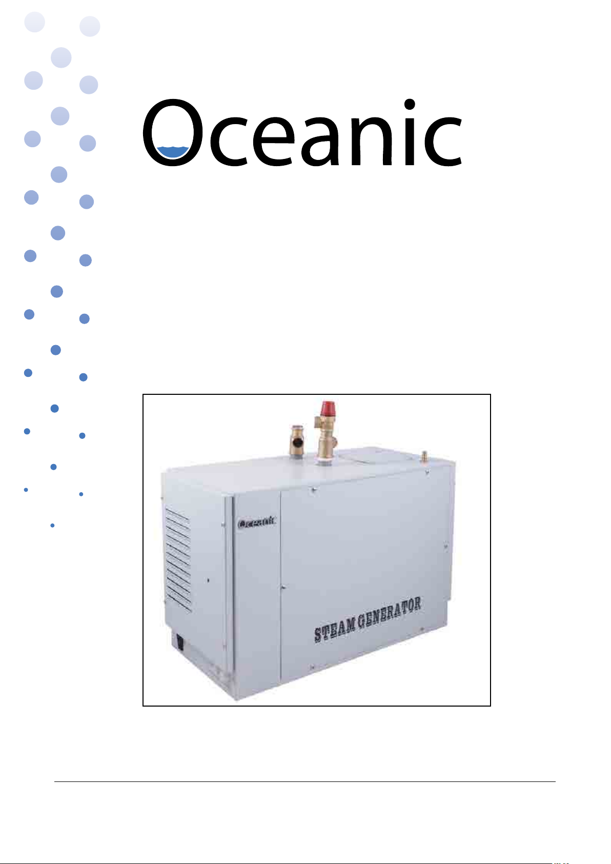
STEAM GENERATOR
PRODUCT IMAGE
15.06.17
Oceanic Ltd, Pountney Street, Wolverhampton, WV2 4HX
Phone: 01902 450 550 sales@oceanic-saunas.co.uk www.oceanic-saunas.co.uk
Page 2

Steam Generator Manual
Sauna & Steam
Table of contents
1. Introduction . . . . . . . . . . . . . . . . . . . . . . . . . . . . . . . . . . . . . . . . . . . . .3
2. Important Notes . . . . . . . . . . . . . . . . . . . . . . . . . . . . . . . . . . . . . . . . . . . 3
3. Safety Precautions . . . . . . . . . . . . . . . . . . . . . . . . . . . . . . . . . . . . . . . . .3
4. Electrical connection . . . . . . . . . . . . . . . . . . . . . . . . . . . . . . . . . . . . . . . . 3
5. Specication . . . . . . . . . . . . . . . . . . . . . . . . . . . . . . . . . . . . . . . . . . . . . 4
5.1. Steam Generator Unit Parameters . . . . . . . . . . . . . . . . . . . . . . . . . . . . . . 4
5.8. Wiring multiple steam generators . . . . . . . . . . . . . . . . . . . . . . . . . . . . . . 5
5.2. Steam Generator Frame Sizes . . . . . . . . . . . . . . . . . . . . . . . . . . . . . . . . . 6
5.3. Clearance distances . . . . . . . . . . . . . . . . . . . . . . . . . . . . . . . . . . . . . . . 6
5.4. Ventilation . . . . . . . . . . . . . . . . . . . . . . . . . . . . . . . . . . . . . . . . . . . . . 6
5.5. Steam Generator Parts Description . . . . . . . . . . . . . . . . . . . . . . . . . . . . . 7
5.6. Table 2. OC-D Controller Parameters . . . . . . . . . . . . . . . . . . . . . . . . . . . . 8
5.7. Temperature Sensor Parameters . . . . . . . . . . . . . . . . . . . . . . . . . . . . . . . 8
6. OC-A Controller Description . . . . . . . . . . . . . . . . . . . . . . . . . . . . . . . . . . . 9
7. Installation . . . . . . . . . . . . . . . . . . . . . . . . . . . . . . . . . . . . . . . . . . . . . 10
7.1. Generator Size . . . . . . . . . . . . . . . . . . . . . . . . . . . . . . . . . . . . . . . . . 10
7.2. Steam Generator Location . . . . . . . . . . . . . . . . . . . . . . . . . . . . . . . . . . 11
7.3. Water and Steam Connections . . . . . . . . . . . . . . . . . . . . . . . . . . . . . . . 12
7.4. Installation for controller and temperature probe. . . . . . . . . . . . . . . . . . . . 13
7.5. Installations for power supply and control cable . . . . . . . . . . . . . . . . . . . 13
7.6. Installing a light . . . . . . . . . . . . . . . . . . . . . . . . . . . . . . . . . . . . . . . . 13
8. Steam on Demand Function (Only supplied with commercial generators) . . . . . 14
9. Circuit Diagrams . . . . . . . . . . . . . . . . . . . . . . . . . . . . . . . . . . . . . . . . . . 14
10. Testing and operation . . . . . . . . . . . . . . . . . . . . . . . . . . . . . . . . . . . . . . 16
10.1. Setting time and temperature. . . . . . . . . . . . . . . . . . . . . . . . . . . . . . . . 16
10.2. Steam on Demand . . . . . . . . . . . . . . . . . . . . . . . . . . . . . . . . . . . . . . . 16
11. Troubleshooting guide . . . . . . . . . . . . . . . . . . . . . . . . . . . . . . . . . . . . . . 17
12. Maintenance . . . . . . . . . . . . . . . . . . . . . . . . . . . . . . . . . . . . . . . . . . . . 18
12.1. Descaling procedure . . . . . . . . . . . . . . . . . . . . . . . . . . . . . . . . . . . . . 18
13. Guarantee . . . . . . . . . . . . . . . . . . . . . . . . . . . . . . . . . . . . . . . . . . . . . . 19
Oceanic Saunas 01902 450 550 sales@oceanic-saunas.co.uk
2
Page 3

Steam Generator Manual
Sauna & Steam
1. Introduction
Thank you for choosing to buy our Oceanic steam generator, please take the time to read these
instructions before you begin as they contain important information about the installation and
maintenance requirements.
“Oceanic” heavy duty steam generators are available in specications from 6kw to 12kw and are
equipped with a programmable thermostatic controller. The controller is set with the time and
day and allows you to program the generator to turn on and o automatically when you require,
the generator can also bet set to clean itself automatically. Once these settings have been saved
the machine can be left to work on it’s own. The machine still must be checked on a regular basis
for safety.
It is also possible to have the generator working o a push button which you place outside of the
steam room, when customers push the button it illuminates and they get 30 minutes of steam.
The machine can also just work on a count down timer for say the next 90 minutes.
Our display tells you everything that the generator is doing, if it takes in water, heats, reached
temperature, draining, descaling, light on, fan on, timer set.
You can also Lock the keys so other users can’t play with the settings. light of the steam room, the
automatic drain valve, key-lock, alter the temperature display between Centigrade and Fahrenheit;
as well as displaying the steam generator‘s status by the 8 LED’s on the panel, heating, water inlet,
temperature, drain status etc. note also that one “OC-D” controller can control multiple “Oceanic”
steam generators.
Every “Oceanic” steam generator is thoroughly tested before leaving the factory so there may be
the remains of water inside the boiler.
2. Important Notes
• Read the manual before installation and operation.
• This Equipment must be installed by competent person.
• This equipment must be connected to an all pole isolator
• Disconnect the power supply before exposing electrical connections.
• Conrm the correct voltage to your steam generator 1 or 3 phase.
• For hard water areas please use a water softener.
• Water supply must have maximum of 1 bar pressure, we recommend the use of a pressure
reducing valve if necessary
3. Safety Precautions
• Elderly persons, pregnant women, or these suering heart disease, high blood pressure,
diabetes or not in good health are advised to seek medical opinion before using a steam room.
• Do not smoke in the steam room.
• Avoid using the steam room immediately after strenuous exercise.
• Do not use the steam room when under the inuence of alcohol.
• Leave the steam room at once if you feel sleepy, sick or uncomfortable.
• Ensure there is good ventilation for the steam room.
• We do not recommend that children under 16 use this product.
• Commercial operators should post a notice of these precautions in a prominent position.
Steam entering the steam room will be scalding hot; take care to position the inlet nozzle
away from where users will sit and/or provide adequate guarding, post a notice to caution
users.
Oceanic Saunas 01902 450 550 sales@oceanic-saunas.co.uk
3
Page 4
Steam Generator Manual
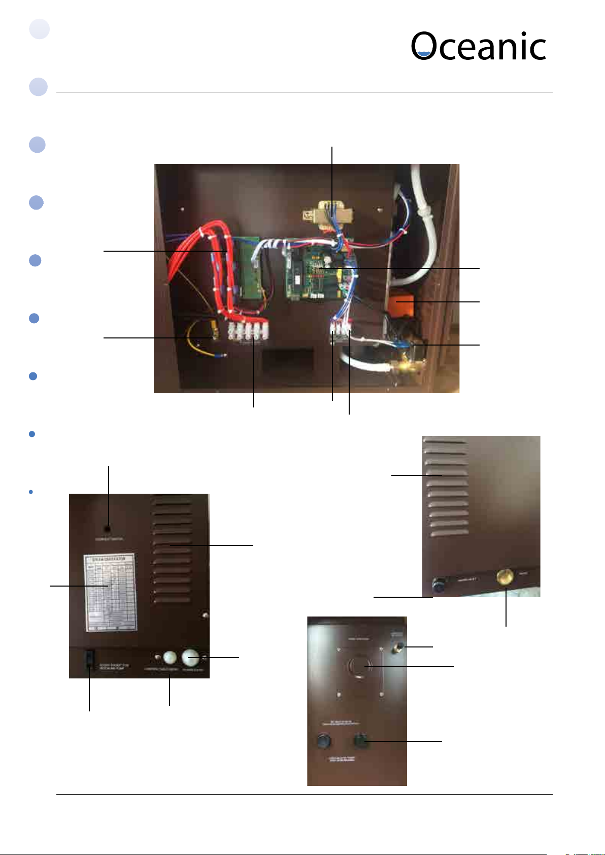
4. Steam Generator Parts
9
Sauna & Steam
1
2
3
15
8
10
7
4
6
5
11
11
17
12
13
14
Oceanic Saunas 01902 450 550 sales@oceanic-saunas.co.uk
18
16
19
20
4
Page 5

Steam Generator Manual
Sauna & Steam
No. Part Description
1 Transformer 240v - 9v + 12v
2 Main Circuit Board Control Centre
3 Drain Valve 3/4” Motorised Ball Valve
4 Inlet Valve 240v Brass Solenoid Valve
5 Light Connection 230v Light Output Switched by Keypad Max (100w)
6 Fan Connection 230v Fan Output Switched by Keypad Max (100w)
7 Power In Connection Terminal for connection of 230 or 400v power.
8 Earth Connection Earth Connection
9 Relay Circuit Board Electrically operated switches for elements.
10 Overheat switch Boil dry protector operates at 105oC Use Pin to reset
11 Louvers Ventilation
12 Main Power Cable Entry Cable entry and restraint for in coming power.
13 Control lead entry Cable entry for control wire.
14 Descaling Pump
Socket for descaling pump
Connection
15 Information Chart For info on Model, Voltage, Wattage and Ampage.
16 Drain connection 3/4” Female Brass
17 Water In Connection 1/2 Male Brass
18 Acid Inlet Hose Nipple for Silicone Descaling Tube Secure with
cable tie
19 Water Probe Access Water Probe Access Plate
20 Steam Outlets 3/4” male steam outlets. Use brass ttings supplied
Oceanic Saunas 01902 450 550 sales@oceanic-saunas.co.uk
5
Page 6
Steam Generator Manual
Sauna & Steam
5. Electrical and plumbing connections
A qualied electrician will have no problem installing this system with the provided wiring
schematic and with the help of the circuit diagram mounted inside the respective control unit.
According to the valid regulations, the electrical connection of the steam generator and the
control box has to be carried out by an authorised electrician. In case of a warranty claim, you are
kindly requested to present a copy of the invoice from the electrician.
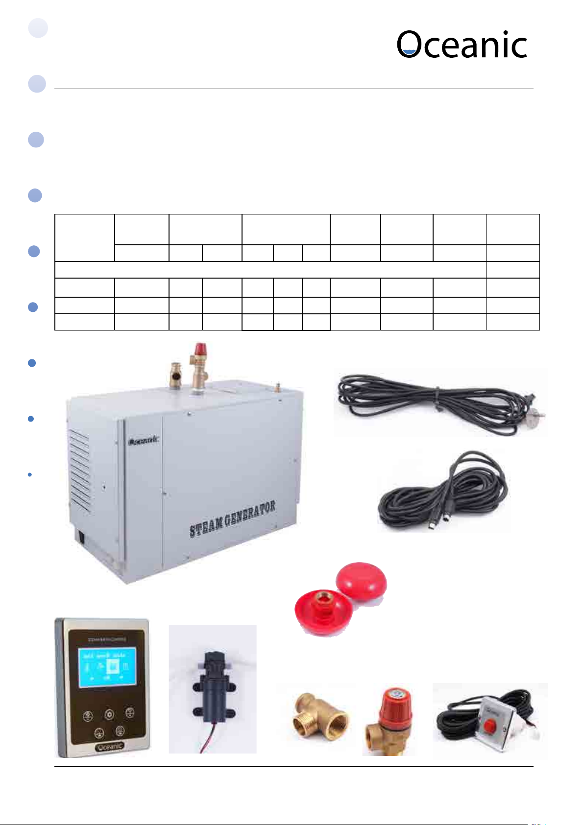
Model Power Current
(amps)
Size (mm) Steam
outlet
Water
Inlet
Drain Nozzle
Type
Kw 1N~ 3N~ L W H inches inches inches
Steam On Demand
OCD-60 6 26 8.6 535 260 380 3/4 (2of) 1/2” 1/2” Red
OCD-90 9 39 13 535 260 380 3/4 (2of) 1/2” 1/2” Red
OCD-120 12 52 17.3 535 260 380 3/4 (2of) 1/2” 1/2” Red
Temperature Sensor
OC-D Controller
Oceanic Saunas 01902 450 550 sales@oceanic-saunas.co.uk
Descaler Pump
3/4”
Steam outlet
5m DIN cable main
circuit board to
controller
3/4”
Steam Inlet Nozzles
Pressure relief
valve
Steam On Demand
button
6
Page 7
Steam Generator Manual
Sauna & Steam
5.1. Connections diagram and table
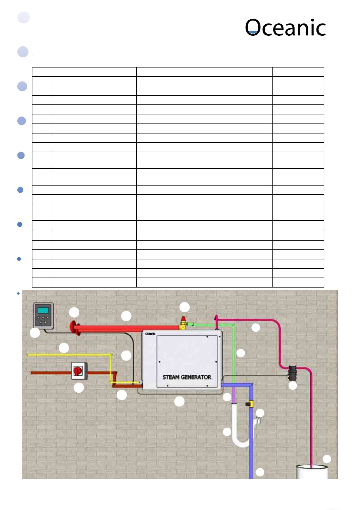
No. Part Description Supplied
1 Water inlet 1/2 “ copper pipe (maximum pressure 1bar) Not supplied
2 Pressure reducer valve Set to 1bar maximum. Not supplied
3 Washing machine trap Both drain and steam overow feed into Not supplied
4 Drain 3/4” exible hose Not supplied
5 Steam Overow 1/2” copper pipe Not supplied
6 Descaler inlet Flexible silicon pipe secured with cable tie Supplied
7 Descaling pump Pumps descaling solution into generator Supplied
8 Descaling solution container Large plastic container lled with descaling solution Optional 120L
9 Pressure relief valve Operates if the pressure in the boiler exceeds 1.2kg/
c m2
10 Brass T junction 3/4” to 3/4” and 1/2” brass tting to t steam pipe
and pressure relief valve
11 Brass T 3/4” T tting for secondary steam outlet Supplied
12 3/4” female cap To block o secondary steam outlet Not supplied
13 Steam pipe Copper pipe from generator to steam inlet
inside steam room (10m max length)
14 Steam inlet nozzle 3/4” nozzle tted inside steam room Supplied
15 Control cable 5m 6 core cable to control keypad Supplied
16 Control keypad To be mounted inside or outside steam room Supplied
17 Lighting circuit 230V cable to lighting circuit (optional) Not supplied
18 Mains input Single or Three phase supply Not supplied
19 Isolator Switch Mains isolator Not supplied
20 Power to descaler pump 230V power cable for descaler pump Supplied
Supplied
Supplied
Not supplied
14
16
17
19
Oceanic Saunas 01902 450 550 sales@oceanic-saunas.co.uk
13
15
18
20
11
6
5
7
4
2
3
8
1
7
Page 8

Steam Generator Manual
Sauna & Steam
16
17
18
15
14
19
20
13
5
3
1
6
2
8
Jubilee clip /
cable tie
1
2
Oceanic Saunas 01902 450 550 sales@oceanic-saunas.co.uk
5
6
Jubilee clip /
20
4
7
3
cable tie
8
Page 9

Steam Generator Manual
5.2. Steam Pipe Connection Options
Sauna & Steam
Option A
Installation with two steam pipes.
Recommended for generators above 9kw
9
10
11
13
13
Important note: Steam outlet must not be reduced
Option B
Installation with one steam pipe
Use a 3/4” female cap to block o the secondary
outlet
13
9
10
12
5.3. Electrical connection schematic
Refer the the circuit diagram on the following page for further details.
230V lighting circuit
Low voltage to
temperature sensor
Low voltage to
Controller
Isolator
switch
Controller
Mains in
230V ~ 1N
400V ~ 3N
Oceanic Saunas 01902 450 550 sales@oceanic-saunas.co.uk
9
Page 10

Steam Generator Manual
D10
AC230V
AC230V
AC230V
AC230V
AC230V
AC230V
AC230V
AC230V
NL
J12
J13
J14
J15
J16
J17
DRAIN
J18
J9
Fro m Transfor mer
F3AL250V
J11
INPUT
J10
OVERHEAT
J7
D9
J6
TEMP2
D8 D7 D6 D5 D4 D3 D2 D1
NONC
Water Inlet
Hi-Temp Cut Off
(Manual Reset)
Light(Max=100W
V=230AC)
Fan
(V=230AC)
Transformer
Temp2
2
4
D10
AC230V
AC230V
AC230V
AC230V
AC230V
AC230V
AC230V
AC230V
NL
J12
J13
J14
J15
J16
J17
DRAIN
J18
J9
Fro m Transfor mer
F3AL250V
J11
INPUT
J10
OVERHEAT
J7
D9
J6
TEMP2
D8 D7 D6 D5 D4 D3 D2 D1
NONC
Water Inlet
Hi-Temp Cut Off
(Manual Reset)
Light(Max=100W
V=230AC)
Fan
(V=230AC)
Transformer
Temp2
2
4
D10
AC230V
AC230V
AC230V
AC230V
AC230V
AC230V
AC230V
AC230V
NL
J12
J13
J14
J15
J16
J17
DRAIN
J18
J9
Fro m Transfor mer
F3AL250V
J11
INPUT
J10
OVERHEAT
J7
D9
J6
TEMP2
D8 D7 D6 D5 D4 D3 D2 D1
NONC
Water Inlet
Hi-Temp Cut Off
(Manual Reset)
Light(Max=100W
V=230AC)
Fan
(V=230AC)
Transformer
Temp2
2
4
5.4. Circuit Diagram
Sauna & Steam
Note: To use the steam generator in single phase the L1 L2 and L3 must be linked
together with the copper bridges that are supplied
YELLOW/ GREEN
BLA CK
BLA CK
22
L1 L2 L3N
AC400V /3N
LN
AC230V /1N
7-12Kw Steam Generator Circuit Diagram
RED
RED
RED
RED
RED
RED
RED
RED
Tank
H1
H2
JP1
Switch C / F
RED
oo
BLUE
WHI TE
WHI TE
RED
RED
RED
Se nsor
Con troller
4
(V= DC5 V)
Con troller
CONT ROL
PANEL
(V=DC 5V)
4
OC- S
P4
J2
Water Lev el Probe
J8
J7
Hi-Temp Cu t Off
(Manua l Res et)
Temp2
OVERHEAT
TEMP2
J10
J6
D10
D8 D 7 D6 D5 D4 D3 D2 D1
D9
J3
From Mas ter
R-CO NTROL
(V= 230 AC)
Transformer
4
J4
TO SLAVE
AC power ad apter
(AC 230V /D C24V)
Fan
2
F3AL250V
J9From Trans former
2
3
Des cale Li quid
Inl et Pu mp
Lig ht( Max=10 0W
V=230AC)
AC230V
L
N
INPUT
J11
J12
AC230V
J13
AC230V
Water Inle t
J14
AC230V
J15
AC230V
J16
AC230V
DRAIN
J17
AC230V
NONC
J18
AC230V
Dra in
Valve
Water Inle t
Valve
2
5.5. Wiring Multiple Generators
If greater power is required one OC-D controller may be used to control two or more steam
generators, e.g. if you need a 24KW steam generator you can use one OC-D controller to control
two 12kw steam generator or three 10kw steam generators.
J4
TO SL AVE
R-C ONTR OL
J3
Fro m Master
J4
TO SL AVE
R-C ONTR OL
J3
Fro m Master
J4
TO SL AVE
To next slave
Master Slave 1 Slave 2
R-C ONTR OL
J3
Fro m Master
Oceanic Saunas 01902 450 550 sales@oceanic-saunas.co.uk
10
Page 11

Steam Generator Manual
6. Parameters
6.1. Steam Generator Frame Sizes
Model A B C D E F
OCD - 60 535 260 380 25 135 45
OCD-90 535 260 380 25 135 45
OCD-120 535 260 380 25 135 45
E
F
Sauna & Steam
C
D
A B
6.2. Clearance distances
>300mm
>500mm
>200mm
>400mm
6.3. Ventilation
Ensure air ow into area where steam generator is housed.
For commercial use ensure good ventilation from at least two ducts within the housing of the
generator
Oceanic Saunas 01902 450 550 sales@oceanic-saunas.co.uk
11
Page 12

Steam Generator Manual
6.4. Table 2. OC-D Controller Parameters
Sauna & Steam
Model Temperature
O
(
C)
o
OC-D 30 - 60
C 155 x 115 x 20
Dimension
(mm)
6.5. Temperature Sensor Parameters
MODEL Detected Scope Max Cut out
Size (mm)
Temperature
o
C
o
F
o
C
o
F L W H
OC-S 0-110 32-230 60 248 76 42 27
Diagram to show location of temperature sensor and steam inlet nozzle
Temperature sensor
1800mm
>500mm
Steam nozzle
300mm
Oceanic Saunas 01902 450 550 sales@oceanic-saunas.co.uk
12
Page 13

Steam Generator Manual
Sauna & Steam
7. Installation
• Isolate the power supply before installation
• Conrm the model you have selected is suitable for your steam room, please refer to chart
below
• Mount the steam inlet nozzle approximately 300mm up from the oor and it should be at least
200mm from person’s body.
• If the steam generator is installed in an inaccessible place ensure that both the electrical
power and water supply can be isolated in an emergency.
• To use the steam generator in single phase the L1 L2 and L3 must be linked together with the
copper bridges that are supplied. See circuit diagram on page 9.
• The minimum water inlet pressure is 0.25 bar (2.5 Mpascals) and the maximum is 2 bar (20
Mpascals), for pressures in excess of this use a reducer before the valve as shown in diagrams
on page 6 and 7.
• The steam pipe from steam generator to steam room should be kept to a minimum, pipes
longer than 3 meters should be insulated to prevent heat loss. Steam pipes will be hot during
use and must be protected against accidental contact. Steam entering the steam room will
be scalding hot; take care to position the inlet nozzle away from where users will sit and/or
provide adequate guarding, post a notice to caution users.
• Keep the number of right angle bends to a minimum and ensure that the run does not create
a trap into which condensate would gather and cause a blockage I.e. the pipe must not go
down and then up.
• There must be no valve or other blockage in the steam pipe
• The steam pipe should be metal of other material that can endure 150°C temperature, copper
pipe is recommended.
• It is not recommended to install the steam generator outdoors or where it might be aected
by frost. Allow for a minimum space of 0.5 cubic meters to install the generator.
• Steam generator should be level side-to-side and front to back and should be installed so that
the arrows on the case point up.
• Do not install the steam generator in close proximity to hazardous substances.
7.1. Generator Size
The table opposite should be referred to for guidance only.
Please note that the size of generator required to heat a
particular size of steam room will vary according to a number
of factors including the type of material used for construction,
the height of the steam room and the ambient temperature.
For lightweight materials such as plastics and laminates 1 KW will
heat up to 1 cubic meter of air for dense materials such as stones
and ceramics which will conduct the heat away more rapidly allow
for up to 2KW per cubic meter of air. Hot air rises so restricting
the height to around 2 meters will ensure the user is sitting in the
steam for higher ceilings you may need to increase the power
requirement.
Oceanic Saunas 01902 450 550 sales@oceanic-saunas.co.uk
Generator Model Steam Room
Volume (m
OC-60 4.5 - 6
OC-90 6 - 10
OC-120 8 - 12
OC-150 11 - 15
3
13
)
Page 14

Steam Generator Manual
Sauna & Steam
7.2. Steam Generator Location
The steam generator should be installed in dry well ventilated place in close proximity to the steam room. It
can be placed on the oor or hung on wall.
To hang the generator on a wall drill 3 holes 8mm in diameter in accordance with the table below. Fix the top
2 screws in place rst then hang the generator by the 2 keyhole shaped holes in the back plate. Then with the
front cover removed x the 3rd screw to secure the unit in place.
465mm
The steam generator can be installed anywhere that is dry and has an airow.
Example locations:
• Plant Room
• Cupboard in an adjacent room
• In the loft
• Up to 1.5m beneath the unit in a basement
Important notes:
• The steam pipe should be insulated and not travel further than 10 metres
• Do not reduce size of steam pipe at any point
• the steam pipe must not go down and then up, as this will create a trap and damage the
steam generator.
<10m
Oceanic Saunas 01902 450 550 sales@oceanic-saunas.co.uk
14
Page 15

Steam Generator Manual
Sauna & Steam
7.3. Water and Steam Connections
i. The water supply pipe and steam pipe should comply with local standards
ii. Connect the water inlet valve of the generator to the mains water supply using a exible
hose with 1/2 inch ttings.
iii. Steam outlet (1/2 inch or 3/4 inch) use the same dimension copper pipe to connect it, if the
steam pipe is longer than 5 meter it should be insulated. During use the steam pipe will
be very hot and must be protected against accidental contact. Note that according to the
location it may be necessary to attach an additional length of pipe to the pressure relief valve
in order to divert the steam ow to a safe direction should the valve operate.
iv. Connect the drain outlet to a suitable drain via a copper pipe with the appropriate ttings.
7.4. Installation for controller and temperature probe.
OC-D controller is waterproof and can be installed inside or outside the steam room according
to customer preference.
i. For a better connection and to eliminate any future connection problems spray connection
uid or aerosol oil spray on the pins of the PS/2 cable(5pin cable) before plugging into the
circuit board.
ii. Ideally the control panel should be installed at a height of approximately 1200mm for ease of
use.
iii. Installation method: Open the front cover of steam generator. Pin the control cable (6 cores)
and temperature sensor cable (2 cores) to the relevant ports.
iv. Control panel installation: pin one end to circuit board ports in steam generator connect the
other end to the controller’s cable.
v. Temperature probe installation: the temperature probe is installed inside the steam room at
approximately 1.2 to 1.5 meters high and away from the steam outlet. Use a 4mm screw x it
in place and then connect to the wire from the controller.
vi. Fix protective cover (supplied) over the temperature
Temperature Sensor
4mm Screw
Oceanic Saunas 01902 450 550 sales@oceanic-saunas.co.uk
Cover to protect the temperature sensor
15
Page 16

Steam Generator Manual
Sauna & Steam
7.5. Installations for power supply and control cable
Conrm the correct voltage of power supply and wires.
Remove the knock out for the power cable entry and use a rubber grommet to protect the cable,
connect to the conductors to the correct terminals – for single phase power supply use the copper
bridge connectors, for 3 phase supply remove them. (Extra bridges can be found it provided)
Remove the knock out for the control cable entry and use a rubber grommet to protect the cable,
connect the cable to the relevant port on circuit board.
Ensure the power supply wire and control cable remain separated to prevent magnetic eld of
power supply wire from disturbing control cable signal.
7.6. Installing a light
There is a 230v power supply inside the steam generator labelled “Light”. This is rated to 100w
Max. The button on the keypad will turn this power supply o and on. This power supply is
protected by a fuse on the main circuit board but you can add your own fused spur for extra
protection if you prefer.
7.7. Installing a Fan
Same as above for a light.
7.8. Connecting to descaler
i. OCD Generator is able to run automatically descale cycle by pumping descaling solution
directly into the tank. This can be set to occur at regular intervals using the contoller as
described on page 20.
ii. The pump supplied should be connected via silicon hose to the generator and the container
of descaling solution.
iii. The diagram on pages 6 and 7 show how the descaling solution should be connected via the
pump. Ensure the the ends of the hose are held in place with cable ties.
iv. Both descaling crystals and 120 litre container can be purchased from Oceanic-Saunas.co.uk
8. Steam on Demand Function
Commercial operators may wish to take advantage of the steam on demand function which
will allow customers to press the steam on demand button located inside or outside the steam
room after which the generator will create steam for 30 minutes then return to an idle state until
activated again. This function reduces running costs and frequency of maintenance.
See instructions on page 19 for how to set up the function on the OCD Controller.
Oceanic Saunas 01902 450 550 sales@oceanic-saunas.co.uk
16
Page 17

Steam Generator Manual
9. Programmable Controller User Instructions
9.1. Display and Buttons
1 Time 24hr
2 Heat Symbol
3 Current Temperature In Room
4 Work Mode e.g Normal, SOD, Auto
5 Centrigrade or Farienheit
6 Set Temperature Has Been Reached
7 Descale Cycle On
8 Draining
9 Water Needed, Filling - Valve Open
If ashing - No Water Supply
10 Generator Has Overheated
Sauna & Steam
11 Fan On
15
16
17
12 Light On
13 Keypad Locked
14 Auto Timer Set
15 Fan On / Decrease (-)
16 Setting
17 Drain (Must Be O) / Increase (+)
18 Light On / Left Scroll
19 Machine On/O / Right Scroll
1918
9.2. Turning On/O
When power has been switched on to the machine the keypad will sound a short beep to indicate that it has
been powered up.
To turn on push
You should now see the default display which should look like this.
Oceanic Saunas 01902 450 550 sales@oceanic-saunas.co.uk
17
Page 18

Steam Generator Manual
Sauna & Steam
9.3. Time and Day
Push push until you reach Push for ok
You can now use the increase and
decrease, left and right buttons to
set the hours, minutes and day.
9.4. Setting Temperature
i. You can set the temperature between 35 and 600C and between 95 and 1400F.
ii. If you are a novice user we advise to start at around 38oC and when you are comfortable with this
temperature start to increase slowly by 1oC between each bathing session.
Increase
Push
Push
Push
or
to enter
setting
to enter
temperature
settings
to save
Decrease
Oceanic Saunas 01902 450 550 sales@oceanic-saunas.co.uk
18
Page 19

Steam Generator Manual
9.5. Working Modes
Sauna & Steam
i. Mode A - This is a count
down timer. You can set
for upto 4 hours or for
continuos heating.
iv. Mode B - Steam On
Demand. (Commercial
only) Install a button
outside of the steam
room, when a customer
pushes the button they
get 30 minutes of steam.
With steam on demand
you only need to set the
temperature of the room.
When the red button is
push it will illuminate to let
users know the generator
is working. Once set the
home screen should look
like this.
v. Mode Auto - Program specic
times for the generator to
turn on and o throughout
the day. Once setup machine
will remember to turn on
or o at these same times
everyday.
ii. Change the time using
the up and down keys.
Press
to save the
setting
vi. You can choose in the morning from between 0.00 - 12:00
noon. And in the afternoon from 12:00 - 23:59.
vii. To activate morning(1) or afternoon(2) change the X to a Tick,
iii. Once set the home screen
should look like this.
now set the time you want the machine to turn on and o. As
you can see above we have set from 6 to 12 in the morning
and from 12 noon to 23:55 at night.
viii. Once setup the home screen
should look like this.
ix. If you isolate power to the
machine it will forget your
settings and go back to
default.
Oceanic Saunas 01902 450 550 sales@oceanic-saunas.co.uk
19
Page 20

Steam Generator Manual
Sauna & Steam
9.6. Auto Descale
i. Set the machine to automatically descale itself once per week. Once set the machine will
descale itself at the same time every week.
ii. The descaling solution will still need to be topped up, our 120 litre drums will do about
10 descales before relling with acid. Mix 5kgs of acid for the whole 120 litres of acid or
around 40-50gs of acid per litre.
iii. For some operators is may not be neccessary for you to be descaling the generator every
week as you may not be in a hard water area or you may only be operating the machine
for a few hours per day. In this case we advise not to have the machine set up for a regular
descale and to only turn the descaling cycle on when you need it. You must remember
though that once the cycle has been completed you must turn the Tick to a X to turn the
weekly descale o.
Push
To setup
descaling push
to enter
iv. The default is Sunday between midnight 00:00 and 8:00 in
the morning.
v. To activate descale change the X to a Tick.
vi. You can also adjust the day and time that the descale will
operate. We advise a minimum of 4 hours.
vii. Note the screen must be turned o for the descale cycle to
run.
9.7. Drain
i. You won’t ever really need to drain the machine as it automatically drains itself. While steaming
the generator will drain out the water so that there is never a concentrated solution of limescale
in the tank. It will also completely drain and ush itself after it has been turned o. (not isolated)
ii. To drain the machine you rst need the screen to be o, so if it is already on push the On/o
button to turn it o. Now push the Drain button, scree will illuminate and indicate the drain
symbol as shown below on the right.
Oceanic Saunas 01902 450 550 sales@oceanic-saunas.co.uk
20
Page 21

Steam Generator Manual
Sauna & Steam
9.8. Light and Fan
i. The light and fan will stay on if the keypad is o, so that if you use the room as a shower the light
can still remain on.
ii. To turn the fan or light on or o just push the button with the light or fan symbol.
iii. The Light has maximum load of 100watts, the Fan has a maximum load of 100watts.
9.9. Screen Lock
i. To lock the screen push the ‘+” button for 5 seconds.
ii. When the controller is locked the ‘light’ button and ‘on/o ‘ button will still be functional.
10. Troubleshooting guide
Please note that we recommend all repairs are carried out be a suitably qualied person.
Trouble description Cause
Something is wrong with:
No Steam Settings not correct
Connection
Power supply
Transformer.
Main circuit board controller
Control cable or port
Connection
Fuse
Water coming out of steam
nozzle.
Circuit breaker tripping
out.
Temperature window
displays “LC”
Temperature window
display “HC”
Water runs through steam
nozzle in room.
Generator works when
switched o on the control
panel.
Filling symbol is ashing Check water supply
Overheat symbol Overheat sensor tripped
Water Level Probe Remove and clean water level probe
Element failure
Loose Earth Wire
Faulty connection
The temp sensor connection 1. Check connection or change temp sensor.
Temp sensor is short circuit. 1. Check connection or change temp sensor.
Water inlet valve.
Level sensor.
Relays 1. Replace relay PCB.
within generator
Solution
Has the control been set up correctly, follow user guide
page 19.
Is water light on - check water supply - check valve coil
for continuity.
Remove and clean water level probe with emery cloth
Descale machine
Check fuse
Check power output from transformer
Replace Main PCB
Check connections to and from water level probe
Check water pressure is <1bar
1. To check elements use a insulation tester, or fault nd
by disconnecting individual elements one by one.
2. Check earth connections are tight.
3. Check drain valve
4. If above fails, return generator to supplier for repair,
guarantee information below.
2. If above fails replace sensor.
2. If above fails replace sensor.
1. Turn machine o, if water continues clean inlet valve
or replace.
2. If runs while machine is on try above if fails clean
water probe and check connection to circuit board.
Clean probe and descale
Reset Overheat button manually on the side of
the generator (see page 4 - part No.10) using small
screwdriver through hole. If in doubt remove casing to
reset
Oceanic Saunas 01902 450 550 sales@oceanic-saunas.co.uk
21
Page 22

Steam Generator Manual
Sauna & Steam
11. Maintenance
The single biggest problem with steam generation is the build up of scale resulting from
dissolved solids within the water. Scaling can cause the elements to fail, the water level sensors
not to function, premature failure of the O-rings resulting in leaks from around the elements. The
extent of the problem will vary according to the degree of hardness in the local water supply.
For all commercial operators we recommend the use of a water softener.
Expect 2500 hours element life, this can be serious depleted by poor maintenance.
All users commercial and domestic must ensure a regular maintenance routine to descale
the generator – the frequency of this will vary according to the degree of hardness in the
local water supply and the amount of time the generator is used for. Check the water for
hardness and arrange the descaling routine accordingly: High levels of hardness descale once every 50 to 100 hours of operation.
Medium levels of hardness descale once every 100 to 250 hours operation.
Low levels of hardness descale once every 250 to 1000 hours of operation.
To descale the generator use a solution of weak acid crystals (such as citric acid) mixed with
water
Citric acid can be purchased from:
www.thebathingplace.com
www.oceanic-saunas.eu
12. Guarantee
All generators are guaranteed for 12 months for domestic and commercial use from the date of
purchase. This guarantee excludes consumable items such as the electrical elements and failures
resulting from misuse or abuse such as a not descaling the machine.
If you are using the generator for more than 20 hours a week in a hard water area without a
water softener your guarantee will be invalidated.
If you encounter any diculty with this assembly procedure or think we could have explained
anything more clearly we would welcome your comments, please call T: 01902 655425 or T:
01902 871127 technical help line.
Oceanic Saunas 01902 450 550 sales@oceanic-saunas.co.uk
22
 Loading...