

Page 1
REGULATORS
GT-3 SECOND STAGE
OCEANIC
GT-3
SERVICE
PROCEDURE
®
This GT-3 Product Service Procedure conveys a list of components and service
procedures that reflect the GT-3 as it was configured at the time of this writing (2/19/05).
Doc. 12-2804-r01 (2/19/05)
© 2002 Design, 2005
PG-1
OCEANIC® Product Service Guide
Page 2
REGULATORS
GT-3 SECOND STAGE
CONTENTS
TROUBLESHOOTING .................................................................................................................................................................2
DISASSEMBLY PROCEDURE ....................................................................................................................................................3
REASSEMBLY PROCEDURE .....................................................................................................................................................7
FINAL TUNING AND TESTING ...................................................................................................................................................8
PARTS LIST AND EXPLODED VIEW DIAGRAM ..................................................................................................................... 11
GENERAL PROCEDURES
REFER TO ...............................................................................................................................................................DOC. 12-2202
SPECIFICATIONS
Torques
P/N 4330 Inlet Coupling 100 to 120 in-lbs
P/N 4787.2 Adjust Knob Screw 4 to 5 in-lbs
P/N 6332 Packing Nut 11 to 13 in-lbs
LP Hose 50 to 60 in-lbs
Opening Effort (IP = 140 psi)
1. Leak with Adjustment Knob turned fully out (clockwise).
2. No leak with Adjustment Knob turned in (counter clockwise)
1-1/2 turns.
3. Minimum effort with no leak = 1.2 inches of H2O or less.
TOOLS REQUIRED
Standard Tools
Inch pounds Torque Wrench
1/4" Open End Wrench
3/4” Crows Foot Wrench
11/16” Crows Foot Wrench
Standard Screwdriver - small
Cotton Swab
Specialty Tools
P/N 40.2302 Christo-Lube MCG111 - 2 oz
P/N 40.3362 Poppet Tool
P/N 40.9315 Intermediate Pressure Gauge
P/N 40.9510 In-line Adjustment Tool
P/N 40.9520 O-ring Tool Kit
P/N 40.9650 Universal Front Cover Tool
© 2002 Design, 2005
PG-2
Doc. 12-2804-r01 (2/19/05)
OCEANIC® Product Service Guide
Page 3
REGULATORS
GT-3 SECOND STAGE
TROUBLE SHOOTING
SYMPTOM POSSIBLE CAUSE TREATMENT
* Free flow or leakage present.
ADJUSTMENT KNOB (33)
turned in.
* Excessive inhalation resis-
tance. ADJUSTMENT KNOB
(33) turned out.
* Rattle heard inside Second
Stage.
1. LEVER ARM (17) bent.
2. Excessive intermediate pressure.
3. Damaged or worn POPPET SEAT
(14).
4. Damaged ORIFICE (11).
5. LOCK NUT (20) overtightened onto
POPPET (15) shaft.
6. WASHER (18) bent or distorted.
7. ORIFICE (11) incorrectly adjusted.
8. POPPET SPRING (16) worn or
weakened, or incorrect part.
9. INLET COUPLING (12) not sufficiently
tightened into HOUSING (4) Inlet
Tube.
10. Trapped debris.
1. LOCK NUT (20) overtightened onto
POPPET (15) Shaft, causing excessive
POPPET SPRING (16) tension.
2. LOCK NUT (20) insufficiently tightened
onto POPPET (15) Shaft, causing
LEVER ARM (17) slack.
3. LEVER ARM (17) bent.
4. ORIFICE (11) incorrectly adjusted.
5. Insufficient Intermediate Pressure from
First Stage.
1. Gravel or sand trapped inside
HOUSING (4).
2. LEVER ARM (17) slack present.
1. Replace with new.
2. Refer to First Stage Troubleshooting
Chart.
3. Replace with new.
4. Replace with new.
5. Replace with new and readjust.
(Refer to tuning section.)
6. Replace WASHER (18), SPACER
(19), and LOCK NUT (20) with new.
7. Turn in clockwise to adjust. (Refer
to tuning section.)
8. Replace with new.
9. Follow correct procedure given in
Reassembly Section to tighten.
10. Remove and clean.
1. Replace with new and readjust.
(Refer to Tuning Section.)
2. Tighten to correct Spring load and
Lever height. (Refer to Tuning
Section.)
3. Replace with new.
4. Adjust to correct contact. (Refer to
Tuning Section.)
5. Refer to First Stage Troubleshooting
Chart.
1. Remove and clean.
2. Tighten LOCK NUT (20) onto
POPPET (15) Shaft. (Refer to
Tuning Section.)
* Little or no airflow when Purge
Button is depressed.
* ADJUSTMENT KNOB (33)
difficult to turn.
* Water entering Second Stage.
© 2002 Design, 2005
1. FRONT COVER (2) not sufficiently
tightened into HOUSING (4).
2. LEVER ARM (17) slack present.
3. ORIFICE (11) incorrectly adjusted.
1. Debris or corrosion present on
ADJUSTMENT SHAFT (29).
2. Debris present inside ADJUSTMENT
KNOB (33).
3. Debris or corrosion present on
ADJUSTMENT SPRING (27).
1. Tear in MOUTHPIECE (8).
2. EXHAUST VALVE (6) distorted or
damaged.
3. DIAPHRAGM (3) distorted or damaged.
4. Debris trapped beneath EXHAUST
VALVE (6).
5. FRONT COVER (2) insufficiently
tightened onto HOUSING (4).
6. Cracked or damaged HOUSING (4).
7. Mouthpiece TIE WRAP (7) loose or
missing.
PG-3
1. Tighten COVER RING (1) until
secure.
2. Tighten LOCK NUT (20) onto
POPPET (15) Shaft. (Refer to
Tuning Section.)
3. Adjust ORIFICE (11) to correct
contact. (Refer to Tuning Section.)
1. Disassemble and clean.
2. Flush out or disassemble if
necessary to clean.
3. Disassemble to clean or replace
with new if necessary.
1. Replace with new.
2. Replace with new.
3. Replace with new.
4. Remove and clean.
5. Tighten until secure and properly
aligned.
6. Replace with new.
7. Tighten or install.
Doc. 12-2804-r01 (2/19/05)
OCEANIC® Product Service Guide
Page 4
REGULATORS
GT-3 SECOND STAGE
DISASSEMBLY PROCEDURE
NOTE: Be sure to perform the steps outlined in the Initial
Inspection Procedures (Doc. 12-2202) prior to disassembling the Regulator. Review the Troubleshooting Section to
gain a better idea of which internal parts may be worn, and
to better advise your customer of the service that is needed.
1. Snip the TIE WRAP (7) that holds the MOUTHPIECE (8), and
remove the MOUTHPIECE. Inspect the condition of the MOUTHPIECE to ensure that it is supple and free of any tears or
corrosion. Discard if found.
2. Remove the Hose from the Second Stage, using an 11/16" open
end wrench, while holding the Hex portion of the INLET COUPLING (12) secure with a 3/4" open end wrench.
3. Remove the COVER RING (1) using a universal Front Cover tool
if necessary, and remove the FRONT COVER (2) to expose the
DIAPHRAGM (3).
Fig. 1
4. Grasp the DIAPHRAGM (3) by the Raised Edges of the Center,
and lift with a slight upward twist to remove. Inspect the
DIAPHRAGM to ensure it is supple and free of any tears,
corrosion, or other distortion. Discard if found.
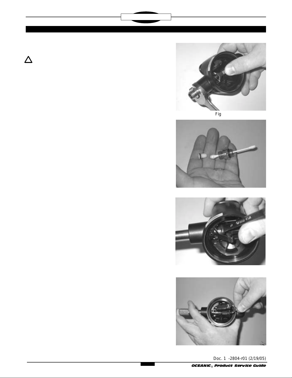
5. Depress and hold the LEVER ARM (17) to remove the INLET
COUPLING (12) in a counter clockwise direction, using a 3/4"
open end wrench (Fig. 1).
6. Remove the COUPLING O-RING (13) from the INLET COUPLING (12) and inspect for any signs of decay. Discard if found.
7. Using a narrow slotted blade screwdriver, remove the ORIFICE
(11) by turning it counter clockwise inside the INLET COUPLING
(12). When it has disengaged completely from the threads,
press it out with the use of a cotton swab (Fig. 2).
Use caution to avoid nicking or scratching the delicate Knife
Edge of the ORIFICE as this is done.
Remove and discard the ORIFICE O-RING (10). Inspect the
ORIFICE carefully with the use of a magnifier to ensure that it is
perfectly free of any scoring or nicks. If found, discard and DO
NOT attempt to reuse it.
Fig. 2
Fig. 3
8. While holding the POPPET (15) secure with the Poppet Tool,
loosen the LOCK NUT (20) by turning it counterclockwise using
a Modified 1/4" Open End Wrench (Fig. 3).
9. Using the Poppet Tool, push the POPPET (15) inward in the Inlet
Tube of the HOUSING (4), compressing the POPPET SPRING
(16), and carefully remove the LEVER ARM (17) (Fig. 4).
© 2002 Design, 2005
PG-4
Fig. 4
Doc. 12-2804-r01 (2/19/05)
OCEANIC® Product Service Guide
Page 5

REGULATORS
GT-3 SECOND STAGE
10. Turn the ADJUSTMENT KNOB (33) out completely until resistance is felt. Remove the ADJUSTMENT KNOB SCREW (34)
using a 5/32" hex key and slide the KNOB off the ADJUSTMENT
SHAFT (29). Clean of any thread locking residue.
11. Remove the PACKING NUT (32) by turning it counter clockwise
using a 5/8" open end wrench. Remove the THRUST WASHER
(31) from the ADJUSTMENT SHAFT (29).
12. Using the Poppet Tool, push the POPPET (15) inward in the Inlet
Tube of the HOUSING (4), which will push the SPRING PAD (26),
ADJUSTMENT SPRING (27), and ADJUSTMENT SHAFT (29)
with PISTON SPRING FOLLOWER (28) through the Outer End
of the ADJUSTMENT TUBE (24) (Fig. 5). If the SPRING PAD
does not come out, gently tap the HOUSING in your hand to
remove it.
13. Remove the STEM O-RING (30) from the ADJUSTMENT SHAFT
(29) and examine it for signs of decay or distortion. Discard if
found.
Fig. 5
NOTE: Removal of the PISTON SPRING FOLLOWER (28)
from the ADJUSTMENT SHAFT (29) should not be necessary
unless it is broken or needs to be replaced. In this case
remove it by holding the ADJUSTMENT SHAFT in one hand
and turning the PISTON SPRING FOLLOWER clockwise with
your other hand. Note the that Thread is left handed.
14. Examine the ADJUSTMENT SPRING (27) with a magnifier and
compare it with new to ensure correct tension and length.
Discard if found to be distorted, weakened, or corroded.
15. Using your finger, push the ADJUSTMENT TUBE( 24) into the
HOUSING (4) and remove it by tilting and lifting out (Fig. 6). The
BALANCE SHAFT (21) will retract into the TUBE during removal.
16. Remove the ADJUSTMENT TUBE O-RING (25) from the ADJUSTMENT TUBE (24) and inspect for any signs of decay.
Discard if found.
17. Remove the BALANCE SHAFT (21) by pushing it out of the
ADJUSTMENT TUBE (24) using a cotton swab . Examine the
SHAFT and compare it with new to ensure that it is not bent or
distorted in any way. Discard if distortion is found.
18. Remove the SNAP WASHER (22) by gently inserting a small
screwdriver through one of the Slots in the ADJUSTMENT TUBE
(24). Examine the SNAP WASHER for deterioration. Discard if
found. Remove the BALANCE SHAFT O-RING (23) (Fig. 7).
Discard the O-RING and DO NOT attempt to reuse it.
Fig. 6
© 2002 Design, 2005
PG-5
Fig. 7
Doc. 12-2804-r01 (2/19/05)
OCEANIC® Product Service Guide
Page 6

REGULATORS
GT-3 SECOND STAGE
19. Remove the POPPET (15), POPPET SPRING (16), WASHER
(18), SPACER (19), and LOCK NUT (20) by holding the POPPET
with the Poppet Tool while turning the LOCK NUT counterclockwise using a 1/4" nut driver. To avoid a sudden ejection as they
are disengaged, continuously apply a slight amount if inward
pressure to the POPPET and LOCK NUT.
20. Examine the SPACER (19) for deterioration. Discard if found.
Discard the LOCK NUT (20) and WASHER (18), and DO NOT
attempt to reuse them.
21. Examine the LEVER ARM (17) and compare with new to ensure
that it is not bent or distorted in any way. Discard if found.
22. Examine the POPPET SPRING (16) with a magnifier and compare with new to ensure correct tension and length. Discard if
found to be weakened or corroded.
23. Remove the POPPET SEAT (14) from the POPPET (15) with the
use of a dental type pick. Discard, and DO NOT attempt to reuse.
24. Using the flat end of a brass O-ring Tool or a thin plastic probe,
carefully lift the Retaining Tab Slats of the EXHAUST COVER (5)
from the Retaining Tabs located on the Base of the HOUSING (4)
(Fig. 8). Once the EXHAUST COVER is disengaged from the
Retaining Tabs, push straight down on the Exhaust Porting of the
EXHAUST COVER to remove it from the HOUSING.
25. Inspect the overall condition of the HOUSING (4) and the
EXHAUST COVER (5) to ensure they are free of any stress
cracks or other distortions. Ensure that all Threading on the
HOUSING is in good condition. Discard either if any distortion or
damage is found.
26. Using a soft probe, inspect the condition of the EXHAUST
VALVE (6) to ensure that it is supple and free of any tears or
corrosion, and that it seals completely around the seating surface of the HOUSING (4).
NOTE: If the EXHAUST VALVE (6) is in good condition, it is
not necessary to remove it. The HOUSING (4) may be
cleaned with it attached.
27. If the EXHAUST VALVE (6) requires replacement, it may be
removed by grasping it at the Flange and pulling it straight out,
snipping the Retainer Stem if necessary. Discard.
Fig. 8
© 2002 Design, 2005
PG-6
Doc. 12-2804-r01 (2/19/05)
OCEANIC® Product Service Guide
Page 7

REGULATORS
GT-3 SECOND STAGE
REASSEMBLY PROCEDURE
NOTE: Prior to Reassembly, it is necessary to inspect all
parts, both new and those that are being reused. Check to
ensure that O-rings are clean and supple, and that every part
and component has been thoroughly cleaned and dried.
WARNING: Use only genuine Oceanic parts, subassemblies, and components whenever assembling Oceanic products. DO NOT attempt to substitute an Oceanic part with
another manufacturer’s, regardless of any similarity in shape,
size, or appearance. Doing so may render the product
unsafe, and could result in serious injury or death of the user.
1. Replace the EXHAUST VALVE (6), if removed, into the HOUSING (4) by gently pulling the Retainer Stem through the HOUSING until the Retaining Flange is inside the HOUSING and
properly seated.
2. Replace the EXHAUST COVER (5) onto the Exhaust Tee portion
of the HOUSING (4) by holding the COVER at a slight angle to
the HOUSING with the Bottom raised and mating the Top of it
with the Hinge Tabs on the HOUSING. Ensure that the Top is
aligned, then press the COVER in toward the HOUSING until it
snaps into place (Fig. 9)
3. Place a new POPPET SEAT (14) into the POPPET (15), with the
side that is perfectly smooth facing out. Ensure that it is
completely seated, flush with the Rim of the POPPET. DO NOT
use adhesive.
4. Apply a light film of lubricant to each end of the POPPET SPRING
(16) and place it onto the POPPET (15). Fit the POPPET into the
Pronged End of the Poppet Tool and insert the POPPET Shaft
completely through the Inlet Tube of the HOUSING (4) compressing the SPRING until the Threaded portion of the Shaft is
completely visible inside the HOUSING. Hold in position by
grasping the Tool with your fingers and the outer rim of the
HOUSING with your thumb.
5. Place the WASHER (18) over the Threads of the POPPET (15)
and onto the Shaft, with the Smooth Side facing up. Place the
SPACER (19) onto the POPPET Shaft. Using a 1/4" nut driver
inserted through the Adjustment Port opening of the HOUSING
(4), turn the LOCK NUT (20) clockwise onto the POPPET
Threads until threading is started (Fig. 10).
Fig. 9
Fig. 10
6. Place the Forks of the LEVER ARM (17) over the POPPET shaft
between the WASHER and the SPACER. Relax the POPPET
and watch to ensure that the LEVER ARM stands upright.
7. Then, while still compressing the SPRING (16) with the Poppet
Tool, turn the LOCK NUT (20) further onto the POPPET until 3
threads are showing beyond the outer surface of the LOCK NUT
(Fig. 11). Remove the tools.
© 2002 Design, 2005
PG-7
Fig. 11
Doc. 12-2804-r01 (2/19/05)
OCEANIC® Product Service Guide
Page 8

REGULATORS
GT-3 SECOND STAGE
CAUTION: It is important that 3 Threads of the POPPET (15)
Shaft are adjusted outside the LOCK NUT (20). The LEVER
ARM (17) may otherwise become caught on the end of the
POPPET Shaft, resulting in an uncontrolled free flow.
8. Lubricate and install the BALANCE SHAFT O-RING (23) into the
Small Opening End of the ADJUSTMENT TUBE (24) (Fig. 12A).
Install the SNAP WASHER (22), smooth end down, into the
ADJUSTMENT TUBE directly over the BALANCE SHAFT ORING, causing the WASHER to "snap" securely into position.
Insert the BALANCE SHAFT (21) into the Small Opening End of
the ADJUSTMENT TUBE through the SNAP WASHER and
BALANCE SHAFT O-RING (Fig. 12B).
9. Lubricate and install the ADJUSTMENT TUBE O-RING (25) onto
the ADJUSTMENT TUBE (24). Holding the Smaller End of the
ADJUSTMENT TUBE, insert it, Threaded End first, down into the
HOUSING (4) and angle it into the Adjustment Tube Opening in
the Side of the HOUSING.
Fig. 12A
Ensure that the ADJUSTMENT TUBE Flange mates flat against
the Inner Wall of the Opening. If necessary, grasp the Outer
Threads and rotate the TUBE until the surfaces mate.
10. If previously removed, install the PISTON SPRING FOLLOWER
(28) on the ADJUSTMENT SHAFT (29). Screw it on counter
clockwise, Flat Side first. DO NOT tighten with a wrench.
11. Lubricate and install the STEM O-RING (30) onto the ADJUSTMENT SHAFT (29).
12. Holding the ADJUSTMENT SHAFT (29) vertically, install the
ADJUSTMENT SPRING (27) over the Stem so it rests in the
Concave End of the PISTON SPRING FOLLOWER (28), then
place the SPRING PAD (26) on top with the Small Rounded End
in the SPRING (Fig. 13).
13. Holding the HOUSING (4) with the ADJUSTMENT TUBE (24)
facing down and your index finger inside pressing the TUBE
against the Inner Wall of the HOUSING, insert the ADJUSTMENT SHAFT (29), ADJUSTMENT SPRING (27) and SPRING
PAD (26) up into the TUBE (Fig. 14). This will push the
BALANCE SHAFT (21) partially out the other end of the TUBE
and up against the POPPET (15). Ensure that the BALANCE
SHAFT is properly aligned with the POPPET. Spring tension will
hold the parts in place.
Fig. 12B
Fig. 13
14. Install the THRUST WASHER (31) onto the ADJUSTMENT
STEM (29), then slide the PACKING NUT (32) over the STEM
and thread it onto the ADJUSTMENT TUBE (24) until secure.
Tighten with a 5/8" open end wrench to a torque of 12 in/lbs.
CAUTION: DO NOT over tighten! Doing so will damage the
HOUSING or other parts, requiring their replacement.
© 2002 Design, 2005
PG-8
Fig. 14
Doc. 12-2804-r01 (2/19/05)
OCEANIC® Product Service Guide
Page 9

REGULATORS
GT-3 SECOND STAGE
15. Install the ADJUSTMENT KNOB (33) over the ADJUSTMENT
SHAFT (29) and PACKING NUT (32). Insert the ADJUSTMENT
KNOB SCREW (34) and tighten with a 3/32" hex key to a torque
of 4 in/lbs.
16. Lubricate and install the INLET COUPLING O-RING (13) onto
the INLET COUPLING (12). Install the INLET COUPLING into
the Inlet Tube of the HOUSING (4) with the Smaller Opening
facing in. Tighten clockwise with a 3/4" open end wrench to a
torque of 110 in/lbs.
17. Lubricate and install the ORIFICE O-RING (10) onto the ORIFICE (11). Lubricate the Threads of the ORIFICE with a very thin
film of lubricant and insert the ORIFICE into the INLET COUPLING (12) with the Knife Edge facing in (Fig. 15).
CAUTION: Be careful to protect the delicate Knife Edge of
the ORIFICE as this is done.
18. Using a narrow shafted, slotted blade screwdriver, gently turn
the ORIFICE (11) clockwise into the INLET COUPLING (12) until
the Knife Edge is
NOT continue to turn the ORIFICE any further beyond this point,
which will cause the LEVER ARM (17) to drop. Doing so will also
damage the ORIFICE Seat requiring its replacement.
barely contacting the POPPET SEAT (14). DO
Fig. 15
NOTE: For best sensitivity of touch during step 18, place
your finger gently on the LOCK NUT (20) while slowly truning
the ORIFICE (11). As soon as contact is made, you will feel
the LOCK NUT begin to turn. Hold the screwdriver by the
shaft rather than by the handle.
19. Place the DIAPHRAGM (3) inside the HOUSING (4) with the
Raised center facing up, and ensure that it seats flush at the Base
of the Inner Threads.
20. Place the FRONT COVER (2) directly over the DIAPHRAGM (3),
and ensure that it seats flush. Position the COVER RING (1) onto
the HOUSING (4), taking care to ensure that it is correctly seated
on the Threads. Hand tighten until secure and ensure the
FRONT COVER is properly aligned, with the logo right side up
(Fig. 17). Use the Universal Front Cover Tool, if necessary. DO
NOT over tighten.
21. Secure the MOUTHPIECE (9) onto the HOUSING (4) with a TIE
WRAP (8), positioning the Locking Tab of the TIE WRAP towards
the LP Hose (Fig. 18).
NOTE: Oceanic’s patented Orthodontic Mouthpieces are
designed to accommodate the natural overbite of the human
jaw. Ensure that it is properly positioned.
Fig. 16
Fig. 17
© 2002 Design, 2005
PG-9
Fig. 18
Doc. 12-2804-r01 (2/19/05)
OCEANIC® Product Service Guide
Page 10

REGULATORS
GT-3 SECOND STAGE
22. Lubricate and replace the O-ring inside the Second Stage
Coupling End of the LP Hose. Install the Hose onto the Second
Stage, and tighten to a torque of 55 in/lbs with an 11/16" crows
foot wrench, while holding the hex portion of the INLET COUPLING (12) secure with a 3/4" crows foot wrench (Fig. 19).
FINAL TUNING AND TESTING
FIRST STAGE TESTING
1. Perform the Leak Detection Test specified in the Initial Inspection
Procedure.
NOTE: Refer to the Trouble Shooting Section to determine
the possible cause and treatment of any gas leaks that may
be found.
2. Connect the GT-3 Second Stage LP Hose to a Low Pressure Port
of the First Stage. Ensure that all other Ports are sealed with Port
Plugs, with the exception of an additional Low Pressure Quick
Disconnect Hose.
3. Connect a recently calibrated Low Pressure Test Gauge to the
additional Low Pressure Hose, and connect the First Stage to a
pure air source of 3,000 PSI (20 BAR).
4. Slowly open the valve to pressurize the Regulator, and check the
Test Gauge to ensure that the Intermediate Pressure is set as
recommended in the Specifications for the First Stage used.
NOTE: If the Intermediate Pressure is found to be other than
recommended, refer to that Regulator's Trouble Shooting
Section to determine possible cause and treatment.
TUNING
Fig. 19
1. Prior to Tuning the GT-3, verify the following:
A. 3 Threads on the Shaft of the POPPET (15) extend past the
outer surface of the LOCK NUT (20).
B. The FRONT COVER (2) should be secure and properly
aligned.
C. The ADJUSTMENT KNOB (33) should be turned counter
clockwise 1-1/2 turns from fully open (or out).
D. Connect an In-Line Adjustment Tool between the Low Pres-
sure Hose and INLET COUPLING (12).
D. The MOUTHPIECE (8) should be cleaned and disinfected
with warm, soapy water.
© 2002 Design, 2005
PG-10
Doc. 12-2804-r01 (2/19/05)
OCEANIC® Product Service Guide
Page 11

REGULATORS
GT-3 SECOND STAGE
2. Pressurize the Regulator with a pure air source of 3,000 PSI (20
BAR), and listen to determine that a slight air flow is initially
present. If necessary, use the In-Line Adjustment Tool to turn the
ORIFICE (11) counter clockwise, slightly out, to initiate this air
flow.
NOTE: While pressurized, the slotted blade of the In-Line
Adjustment Tool will be held away from the ORIFICE (11), and
will therefore need to be pushed inward and held while
turning in either direction. Locate the slotted head of the
ORIFICE by touch before attempting any adjustment.
3. Use the In-Line Adjustment tool to turn the ORIFICE (11) in
clockwise using small fractions of a turn just until air flow is no
longer present. Pause to listen carefully for air flow or leakage
after each adjustment.
NOTE: Turning the ORIFICE (11) in further than necessary to
stop air flow will result in LEVER ARM (17) slack and excessive Spring load tension, prohibiting peak performance.
CAUTION: To avoid cutting the POPPET SEAT (14) with the
Knife Edge of the ORIFICE (11), depress the Purge Button
while turning the ORIFICE in or out.
4. Hold the Second Stage with the MOUTHPIECE (8) facing directly
down, and gently shake it up and down. Listen carefully for any
rattle that may be present, indicating LEVER ARM (17) slack. If
found, perform the following procedure:
A. Remove the COVER RING (1), FRONT COVER (2), and
DIAPHRAGM (3) to gain access to the Valve Assembly.
B. Purge the Regulator of air.
C. Depress the LEVER ARM (17) and hold it down to remove the
INLET COUPLING (12) from the Inlet Tube of the HOUSING (4),
using a 3/4" open end wrench.
D. Turn the LOCK NUT (20) further clockwise onto the POPPET
(15) Shaft with small fractions of a turn, using the Poppet Tool and
1/4" open end wrench. Use the correct method given in step 16
of the Reassembly Procedure to replace the INLET COUPLING
after each adjustment, and again determine whether slack is
eliminated.
NOTE: Avoid tightening the LOCK NUT (20) any further than
is necessary to eliminate LEVER ARM (17) slack. It may be
necessary to repeat step 4D several times to arrive at the
correct setting.
CAUTION: Be careful to avoid over adjusting! If air flow
returns, replace the LOCK NUT and POPPET SEAT (14) with
new, and
© 2002 Design, 2005
start over after rereading the above procedures.
PG-11
Doc. 12-2804-r01 (2/19/05)
OCEANIC® Product Service Guide
Page 12

REGULATORS
GT-3 SECOND STAGE
5. Replace the DIAPHRAGM (3), FRONT COVER (2), and COVER
RING (1) if removed, and pressurize the Regulator again with a
pure breathing gas source of 3,000 PSI (20 BAR). Determine the
range of adjustment by performing the following procedure:
A. Turn the ADJUSTMENT KNOB (33) completely out counter
clockwise. A slight to moderate air flow should be present.
B. Turn the ADJUSTMENT KNOB completely in clockwise and
fully depress the Purge Button. This should initiate a slight air
flow.
NOTE: If air flow is greater, or less than, specified for each
adjustment, refer to the Trouble Shooting Section to determine possible cause and treatment.
6. Purge the Regulator of air, remove the In-Line Adjustment Tool
and connect the LP Hose directly on to the INLET COUPLING
(12), using two wrenches as prescribed in step 22 of the Reassembly Procedure.
7. Pressurize the Regulator again with a pure air source of 3,000
PSI (20 BAR). Return the ADJUSTMENT KNOB (33) to its mid
range position. Inhale lightly through the MOUTHPIECE (8) to
determine that air flows easily and smoothly, without any hesitation or lag.
NOTE: If hesitation or lag is detected, refer to the Trouble
Shooting Section to determine possible cause and treatment.
8. Clean and disinfect the MOUTHPIECE (8) in warm, soapy water
before returning the GT-3 to the customer.
© 2002 Design, 2005
PG-12
Doc. 12-2804-r01 (2/19/05)
OCEANIC® Product Service Guide
Page 13

REGULATORS
GT-3 SECOND STAGE
Dia.
No. Part # Description
1c 6408.07 RING, COVER
2c 6292.07 COVER, FRONT (BK)
3b 5236 DIAPHRAGM
4c 5233.07 ASSEMBLY, HOUSING (BK)
5c 5234.07 COVER, EXHAUST (BK)
6b 6326 VALVE, EXHAUST
7c 1978.07 WRAP, TIE
8b 4485.07 MOUTHPIECE (BK)
9c 6438 PROTECTOR, HOSE (BK)
10a 2.010 O-RING, ORIFICE
11c 6621 ORIFICE
12c 4330 COUPLING, INLET
13b 3.906 O-RING, COUPLING
14a 4340 SEAT, POPPET
15c 4333 POPPET
16b 4593 SPRING, POPPET
17c 5254 ARM, LEVER
18a 5117 WASHER
19b 4335 SPACER
20a 4336 NUT, LOCK
21c 5244 SHAFT, BALANCE
Dia.
No. Part # Description
22b 4969 WASHER, SNAP
23a 2.004 O-RING, BALANCE SHAFT
24c 5245 TUBE, ADJUSTMENT
25b 2.016 O-RING, ADJUSTMENT TUBE
26c 4971 PAD, SPRING
27c 4589 SPRING, ADJUSTMENT
28c 6684 FOLLOWER, PISTON SPRING
29c 6685 SHAFT, ADJUSTMENT
30b 2.107 O-RING, STEM
31b 5054 WASHER, THRUST
32c 6332 NUT, PACKING
33c 6359 KNOB, ADJUSTMENT
34c 4787.2 SCREW, ADJUSTMENT KNOB (BK)
35c 40.2100.030 ASSEMBLY, LP HOSE (30")
40.2118.039 ASSEMBLY, LP HOSE (36")
N/S 2.010 O-RING, LP HOSE (SECOND STAGE END)
N/S 3.903 O-RING, LP HOSE (FIRST STAGE END)
N/S 40.6162 KIT, SERVICE PARTS (includes all Bold items)
35
© 2002 Design, 2005
10
9
11
12
13
15
16
4
8
7
5
14
26
27
28
29
30
6
21
22
23
31
32
33
34
24
25
3
2
1
PG-13
18
17
19
20
Doc. 12-2804-r01 (2/19/05)
OCEANIC® Product Service Guide
 Loading...