

Page 1

DataTrans Plus
owner's guide
Page 2

Page 3

DataTrans Plus
Pay special attention to items marked with this Warning symbol.
WARNINGS:
• The DataTrans Plus is intended for use by recreational divers who have successfully completed a
nationally recognized course in scuba diving, and diving with enriched nitrogen-oxygen (nitrox)
mixtures.
• It is intended only for no decompression diving, NOT intentional decompression diving.
• It must not be used by untrained persons who may not have knowledge of the potential risks and
hazards of scuba diving, and diving with enriched nitrogen-oxygen (nitrox) mixtures.
• You must obtain scuba certification, and certification in diving with enriched nitrogen-oxygen
mixtures (nitrox) before using the DataTrans Plus if you have not already done so.
• It is NOT for use by military and commercial divers.
• It should NOT be utilized for any competitive, or repetitive square wave or decompression diving, as
it is intended solely for recreational use and no decompression multilevel diving.
• As with all underwater life support equipment, improper use or misuse of this product can cause
serious injury or death.
• Never participate in sharing or swapping of a dive computer.
• Conduct your dives in such a manner so as to insure that you continuously check the computer's
proper function.
• Read and understand this owner’s guide completely before diving with the DataTrans Plus.
• If you do not fully understand how to use this dive computer, or if you have any questions, you should
seek instruction in its use from your authorized Oceanic dealer before you utilize this product.
iii
Page 4

®
LIMITED TWO-YEAR WARRANTY
Oceanic guarantees, to the original purchaser only, that the DataTrans Plus will be free of defects in materials and/or craftsmanship
under normal recreational multilevel scuba use for two years from date of purchase, provided proper care and annual service are performed as described within this owner’s guide. Should your DataTrans Plus prove to be defective for any reason (other than those listed
in the limitations section below) it will be repaired or replaced (at Oceanic’s discretion) free of charge excluding shipping and handling
charges.
This warranty will be considered void if the DataTrans Plus was purchased from anyone other than an Authorized
Oceanic Dealer, and/or if the registration card is not filled out completely at the time of purchase and mailed to Oceanic within 30 days
of purchase, and/or if the annual inspection is not done according to this owner’s guide. This warranty is non-transferrable and applies to
the original purchaser only. All correspondence concerning this warranty must be accompanied by a copy of the original sales receipt and
a copy of the owner’s portion of the warranty registration card including the annual inspection record.
Once each year you must return the DataTrans Plus to an Authorized Oceanic Dealer within 30 days of the original
purchase date anniversary to keep the two year limited warranty in force. Annual inspection includes verification of depth
accuracy and proper general function. Labor charges for the annual inspection are not covered by the warranty. You must provide a copy
of the original sales receipt and a copy of the owner’s portion of the warranty registration card including the annual service record to
obtain warranty service.
Statement of Limitations - General:
Warranty does not cover damage from accident, abuse, battery leakage, tampering, lack of proper care and maintenance
and/or proper annual servicing, or improper use of the DataTrans Plus. Modifications or repair by anyone other than an
Oceanic Sales & Service Center authorized to service the DataTrans Plus will void the warranty. Oceanic will not be responsible for
recovery or replacement of the product in the event of loss or theft. Oceanic, its distributors, and retailers make no warranties, either
expressed or implied, with respect to this product or its owner’s guide except those stated in the preceding paragraphs. In consideration
of the sale of the DataTrans Plus to you, you agree and understand that in no event will Oceanic, its distributors or
retailers, be held liable for any personal injuries resulting from its operation, or for any other damages whether direct,
indirect, incidental, or consequential even if Oceanic is advised of such damages. Warranty does not extend to plastic
gauge face, o-rings, batteries, or damage due to accident, abuse, modification, or tampering.
Some states do not allow the exclusion or limitation of implied warranties or liabilities for incidental or consequential damages, so the
above limitation may not apply to you.
iv
Page 5

DataTrans Plus
COPYRIGHT NOTICE
This owner’s guide is copyrighted, all rights are reserved. It may not, in whole or in part, be copied, photocopied, reproduced, translated,
or reduced to any electronic medium or machine readable form without prior consent in writing from Oceanic / 2002 Design. The Surface
Time/Mode, Plan Mode, Breathing Gas Time, No Decompression Time, Decompression Stop Time, Dive Log, Transmitter Low Battery,
Receiver Low Battery, Link, Temperature, Elapsed Dive Time, Maximum Depth, Ascent Rate, Breathing Gas Consumption, and Caution
Zone icons are protected by copyright, and are trademarks of Oceanic.
DataTrans Plus Owner's Guide, Doc. No. 12-2022
© 2002 Design 1997
2002 Davis Street
San Leandro, Ca. USA 94577
510/562-0500
TRADEMARK NOTICE
Oceanic, the Oceanic logo, DataTrans Plus, the DataTrans Plus logo, DX3 Integrated, Oceanglo, Graphic Diver Interface, Tissue Loading
Bar Graph, Pre Dive Planning Sequence, Variable Ascent Rate Indicator, Breathing Gas Time Remaining, Message Box, Set Point, Control
Console, and OceanLog are all registered and unregistered trademarks of Oceanic. All rights are reserved.
PATENT NOTICE
U.S. Patents have been issued, or applied for, to protect the following design features:
Graphic Diver Interface, Pre Dive Planning Sequence, Dive Time Remaining, Breathing Gas Time Remaining Bar Graph, Variable
Breathing Gas Consumption Bar Graph, DataTrans Plus Message Box, DataTrans Plus Mode Menu Structure, Breathing Gas Alarm Set
Point, Depth Alarm Set Point, Breathing Gas Time Remaining (U.S. Patent no. 4,586,136), Data Sensing and Processing Device (U.S.
Patent no. 4,882,678), Tissue Loading Bar Graph (U.S. Patent no. 4,882,687), and Variable Ascent Rate Indicator Bar Graph (U.S. Patent
no. 5,156,055).
DECOMPRESSION MODEL
The programs within the DataTrans Plus simulate the absorption of nitrogen into the body by using a mathematical model. This model is
merely a way to apply a limited set of data to a large range of experiences. The DataTrans Plus dive computer model is based upon the
latest research and experiments in decompression theory. Still, using the DataTrans Plus, just as using the U.S. Navy (or other)
No Decompression Tables, is no guarantee of avoiding decompression sickness, i.e. “the bends.” Every diver’s physiology is
different, and can even vary from day to day. No machine can predict how your body will react to a particular dive profile.
v
Page 6

®
FCC ID: MH8A
FCC Compliance:
This device complies with Part 15 of the FCC Rules. Operation is subject to the following two conditions: 1) this device may not cause
harmful interference, and 2) this device must accept any interference received, including interference that may cause undesired operation.
FCC Interference Statement:
This equipment has been tested and found to comply with the limits for an Intentional Radiator, a Class B Digital Device, pursuant to
Part 15 of FCC Rules, Title 47 of the Code of Federal Regulations. These limits are designed to provide reasonable protection against
harmful interference in a commercial or residential installation. This equipment generates, uses, and can radiate radio frequency energy,
and if not installed and used in accordance with the instructions, may cause interference to radio communications.
There is no guarantee that interference will not occur in a particular installation. If this equipment does cause interference to radio or
television reception, which can be determined by turning the equipment on and off, the user is encouraged to try to correct the interference by one or more of the following measures:
a. Reorient or relocate the receiving antenna.
b. Increase the separation between the equipment and the affected receiver.
c. Connect the equipment and the affected receiver to power outlets on separate circuits.
d. Consult the dealer or an experienced radio/TV technician for help.
WARNING: Changes or modifications not expressly approved by Oceanic could void the user's authority to operate
the equipment.
vi
Page 7

DataTrans Plus
CONTENTS
FEATURES & DISPLAYS............................................................ 1
Introduction ..................................................................................................................2
Interactive Control Console .........................................................................................4
Informational Displays.................................................................................................5
Universal Graphic Diver Interface ..............................................................................6
Tissue Loading Bar Graph .......................................................................................7
Oxygen Accumlation Bar Graph..............................................................................8
Variable Ascent Rate Indicator ................................................................................9
Breathing Gas Consumption Indicator .................................................................10
Breathing Gas Time Remaining Bar Graph .........................................................11
Dive Time Remaining.................................................................................................11
Breathing Gas Time Remaining ............................................................................12
No Decompression Dive Time Remaining ............................................................14
Oxygen Accumulation Time Remaining ...............................................................15
Alpha Numeric Displays.............................................................................................15
Cylinder Pressure Display......................................................................................15
Depth Displays........................................................................................................16
Time Displays .........................................................................................................17
Ambient Temperature Display ..................................................................................18
vii
Page 8

®
CONTENTS (continued)
Audible Alarm.............................................................................................................19
Message Box................................................................................................................21
Backlight Feature .......................................................................................................21
Operating Temperature .............................................................................................22
Sharing the DataTrans Plus ......................................................................................23
Graphic Interface Legend ..........................................................................................24
ACTIVATION & SETUP............................................................. 25
Making the DataTrans Plus Personal.......................................................................26
Activating the Display ................................................................................................27
Surface Mode ..............................................................................................................31
Mode Menu System ....................................................................................................31
Entering Settings .......................................................................................................33
Set Time ..................................................................................................................33
Set Date...................................................................................................................34
Set Alternate Display .............................................................................................35
Set Units of Measure ..............................................................................................36
Breathing Gas & Depth Alarm Set Points ............................................................37
Depth Alarm Set Point.......................................................................................37
viii
Page 9

DataTrans Plus
CONTENTS (continued)
Breathing Gas Alarm Set Point .........................................................................38
Set Depth & Breathing Gas Alarms ..................................................................39
Turning Off the Audible Alarm .........................................................................40
Linking Procedure..................................................................................................41
Set Language ..........................................................................................................43
Language Correction Procedure ........................................................................44
PREDIVE & DIVE MODES ....................................................... 45
Positioning of the Display Module.............................................................................47
Link Interruption Underwater ..................................................................................47
Operational Modes......................................................................................................48
FO2 Mode....................................................................................................................49
FO2 Set for Air .......................................................................................................49
Settings FO2 for Nitrox .........................................................................................50
Plan Mode ...................................................................................................................52
No Decompression Dive Mode ...................................................................................55
Decompression Dive Mode .........................................................................................56
Violation Modes ..........................................................................................................57
Gauge Mode ................................................................................................................57
ix
Page 10

®
CONTENTS (continued)
Ascending to the Surface............................................................................................57
Altitude Diving ...........................................................................................................59
POST DIVE MODES .................................................................. 61
Post Dive Surface Mode..............................................................................................62
Transition Period....................................................................................................62
FO2 Mode....................................................................................................................63
Plan Mode ...................................................................................................................63
Time to Fly..................................................................................................................64
Dive Log Mode ............................................................................................................65
History Mode ..............................................................................................................68
External Access Mode.................................................................................................69
HANDLING THE EXTREMES.................................................. 71
Emergency Decompression ........................................................................................72
Gas Time Remaining During Decompression.......................................................75
Caution Zone (C.Z.).................................................................................................76
Decompression Dive Mode .....................................................................................77
x
Page 11

DataTrans Plus
CONTENTS (continued)
Violation Modes ..........................................................................................................79
Conditional Violation Mode ...................................................................................79
Delayed Violation Mode..........................................................................................80
Immediate Violation Mode.....................................................................................83
Gauge Mode ............................................................................................................84
Permanent Violation ..............................................................................................84
Exceeding Maximum Operating Depth.....................................................................85
Oxygen Exposure........................................................................................................86
Partial Pressure of Oxygen ....................................................................................87
High PO2 Dive Mode..............................................................................................87
Oxygen Accumulation ............................................................................................88
High Oxygen Accumulation ...................................................................................89
Message Box Warnings ...............................................................................................90
Unexpected Loss of Displayed Information ..............................................................90
CARE & MAINTENANCE.......................................................... 93
Care and Cleaning ......................................................................................................94
Annual Inspections & Service....................................................................................95
How to Obtain Service ...........................................................................................96
xi
Page 12

®
CONTENTS (continued)
Battery Life.................................................................................................................97
Low Battery Condition ...............................................................................................99
Battery Replacement ..............................................................................................99
Flooded Battery Compartment ............................................................................101
Transmitter Installation Instructions.....................................................................102
Transmitter Compatibilty with Nitrox ...................................................................103
REFERENCE ............................................................................ 105
More About Flying After Diving..............................................................................106
More About Altitude Diving.....................................................................................107
More About Nitrox Diving .......................................................................................109
Multiple Tissue Tracking .........................................................................................110
No Decompression Limits ........................................................................................112
Repetitive Decompression Diving............................................................................112
Specifications ............................................................................................................114
Responsible Computer Diving .................................................................................117
Language Cross Reference .......................................................................................118
Glossary.....................................................................................................................121
Accessories ................................................................................................................125
DataTrans Plus Service Record ...............................................................................126
xii
Page 13

DataTrans Plus
FEATURES
and
DISPLAYS
1
Page 14

®
INTRODUCTION
Welcome to Oceanic and thank you for choosing DataTrans Plus!
Your new DataTrans Plus is a two component, hoseless, integrated system that consists of a computer Display
Module and a radio frequency Transmitter that will be installed into a high pressure port of your regulator
first stage, or is built into an Oceanic DX3™ Integrated first stage regulator. The transmitter sends tank pressure data to the display module via a low frequency signal. In addition to nitrogen and oxygen loading data,
breathing gas consumption is calculated and displayed in graphic and alpha/numerical formats on the
computer’s screen. The Display Module can also be used without the transmitter as a stand alone, non-integrated computer, and will retain full use of all functions except those that related to tank pressure.
Your DataTrans Plus presents the information that you need before, during, and after your air (or nitrox)
dives using Oceanic's intuitive combination of easy to read displays and unique identification icons. Tissue
loading of nitrogen, accumulation of oxygen, ascent rate, breathing gas consumption rate, and breathing gas
time remaining are presented as segmented bar graphs alongside color coded reference indicators that bring
quick focus to these important status displays.
As you progress through this instructional guide, you will become familiar with all of the unique functions and
features available and see examples of the displays that you could expect to see in the various operational
modes. Refer to the Glossary of terms on page 121, and keep the waterproof Review Card handy during your
dive trips. Although it will require an initial investment of time to become acquainted with the various icons
2
Page 15

DataTrans Plus
and bar graphs of the Graphic Diver Interface, you’ll soon agree that the DataTrans Plus is easy to understand and use.
The DataTrans Plus has a wide array of features described in detail throughout the pages that follow. Due to
the importance that they be understood thoroughly prior to using the DataTrans Plus, information will be expanded upon and some refreshed as you proceed. Relax and read through the complete guide.
It is extremely important that you:
• Read this owner's guide in sequence and understand it completely before attempting to use
the DataTrans Plus.
• Check the DataTrans Plus frequently during your dive.
• You must also be a trained diver, certified by a recognized training agency in Scuba diving.
• Prior to using the oxygen related features of the DataTrans Plus, you must also be trained
and certified for diving with enriched nitrogen-oxygen (nitrox) mixtures by a recognized
training agency.
Remember that the rules you learned in your basic scuba certification course still apply to the diving you will
do while using a dive computer - some will become even more important. Technology is no substitute for common sense, and a dive computer only provides the person using it with data, not the knowledge to use it.
Be a RESPONSIBLE DIVER at all times.
3
Page 16

®
INTERACTIVE CONTROL CONSOLE
(Surface Modes)
Oceanglo
Backlight
(Dive Modes)
Fig. 1 - Interactive
Control Console
4
®
®
SelectAdvance
Alternate
Display
The DataTrans Plus is a unique dive computer with interactive controls that
allow you to select various display options and access specific information
when you choose to see it. The Interactive Control Console consists of the Ad-
vance (Left) button and Select (Right) button (Fig. 1).
The control buttons can be pressed repeatedly, releasing upon hearing a beep,
or held in to scroll and continue as you set or access different display modes.
On the surface, before diving, you can perform the following operations using
the Control Console:
• Activate the display module
• Select units of measure - English or Metric
• Select Message Box™ language - English, Italian, German, Spanish, or
French
• Set depth & gas alarm warning level Set Points™
• Turn the audible alarm - on or off
• Turn the Alternate Dive Mode display - on or off
• Set the current date & time
• Set the display module/transmitter link code
Page 17

Also while on the surface, you can access the following modes with the Control
Console:
• FO2 mode - to program the percentage of oxygen in the nitrox mix.
• Plan mode - to view no decompression limits and plan your next dive.
• Log mode - to view data from your 12 most recent dives.
• History mode - to view the total number of dives, maximum depth, etc.
• Set mode - to establish prefered selections.
• External Access mode - to download (copy) dive data from the
DataTrans Plus to a unique PC log/profile program.
During the Dive mode, the Advance (Left) button can be used to activate the
display's Oceanglo™ backlight, and the Select (Right) button can be used to access an Alternate Dive mode, that displays additional information including
maximum depth, bottom time and temperature.
INFORMATIONAL DISPLAYS
DataTrans Plus
NO DECO
C.Z. C.Z.
DECO
O
2
Operational modes and status information is visually represented numerically
and/or graphically and can be understood at a glance with the aide of universal
icons (Fig. 2) that identify and bring quick focus to the displays. Also, segmented
bar graphs will show how close you are to critical limits.
In critical situations, a Message Box™ flashes urgent messages, while an au-
5
10
30
0
20
®
60
40
50
Fig. 2 - Universal Icons
5
Page 18
®
C.Z. C.Z.
NO DECO
0
DECO
5
10
40
30
20
®
50
Fig. 3 - Message Box
C.Z. C.Z.
NO DECO
DECO
PSI
BAR
MAX
FT
M
O
2
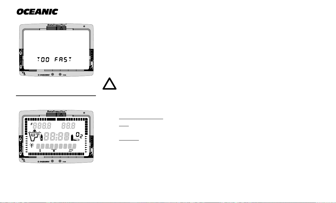
simple messages (Fig. 3), such as “TOO FAST” or “TOO DEEP" are displayed
in the language that you choose during setup.
Each DataTrans Plus numeric and graphic display represents a
unique piece of information. It is imperative that you understand
the formats, ranges, and values of the information represented to
dible alarm sounds to alert you to check this information. These concise,
60
avoid any possible misunderstanding that could result in error.
NOTE: Throughout this owner's guide reference is made to the
term 'breathing gas'. The rational being that the DataTrans
Plus can be used for 'air' dives or 'nitrox' dives. For clarity
these terms are defined as -
O
2
Breathing Gas - the gaseous mixture breathed during a dive.
Air - a breathing gas that contains approximately 21% oxygen
and 79% nitrogen (nature's common nitrogen-oxygen mixture).
Nitrox - a nitrogen-oxygen breathing gas that contains a higher
fraction of oxygen (22 to 50%) than air.
5
10
30
0
20
®
60
40
50
Fig. 4 - Bar Graph Displays
6
UNIVERSAL GRAPHIC DIVER INTERFACE
™
Five bar graphs referred to as the Universal Graphic Diver Interface™ appear
around the perimeter of the DataTrans Plus screen (Fig. 4). These segmented
R2
Page 19

bar graphs are located next to green, yellow, and red color coded portions of the
peripheral decal that denote normal, caution, and danger zones, respectively.
When underwater, you can quickly focus on the bar graphs to make sure that
they are in the green. You can quickly verify that you're not getting too close
to the no decompression limit or the oxygen tolerance limit, or ascending too
fast, or consuming breathing gas too fast, or running low on breathing gas.
DataTrans Plus
Tissue Loading Bar Graph
™
The Tissue Loading Bar Graph™ represents nitrogen loading (Fig. 5), showing
your relative no decompression or decompression status. As your depth and
elapsed dive time increase, segments will add to the graph beginning in the
lower left portion of the screen. As you ascend to shallower depths, this bar
graph will begin to recede, indicating that additional no decompression time is
allowed for multilevel diving.
The Tissue Loading Bar Graph monitors 12 different nitrogen compartments
simultaneously and displays the one that is in control of your dive. It is divided
into a green No Decompression zone (NO DECO), a yellow Caution zone (C.Z.),
and a red Decompression zone (DECO). The bar graph gives a visual representation of just how close you are to the no decompression limit with a yellow
Caution (C.Z.) Zone.
This Caution Zone portion of the bar graph (Fig. 5a) allows you to make a decision regarding safety stop duration or necessity. While you cannot provide a
a
NO DECO
C.Z. C.Z.
DECO
O
2
b
5
10
30
0
20
®
60
40
50
Fig. 5 - Tissue Loading
Bar Graph
7
Page 20
NO DECO
®
C.Z. C.Z.
DECO
guarantee against the occurrence of decompression sickness, you may choose
O
2
your own personal zone of caution based upon age, physique, excessive weight,
etc., to reduce the statistical risk.
FT
The Tissue Loading Bar Graph assists you with managing decompression by
filling a large red 'ceiling stop required' segment (Fig. 5b). Decompression is
explained in detail in the Handling the Extremes section.
5
10
30
0
20
®
60
40
50
Fig. 6 - Nitrogen Control
NO DECO
C.Z. C.Z.
DECO
O
2
a
5
10
30
0
20
®
60
40
50
Fig. 7 - Oxygen Accumulation
(O2) Bar Graph
8
Prior to a repetitive nitrox dive, if all segments of the Tissue Loading Bar
Graph are displayed during the Pre Dive Planning Sequence™, and no segments of the O2 bar graph are displayed (Fig. 6), that next dive is calculated to
be controlled by nitrogen loading.
WARNING: Oceanic advocates responsible diving practices
consistent with your individual level of formal training and experience, and does not recommend decompression diving or
diving below 130 feet (39 m).
Oxygen Accumulation (O2) Bar Graph
NOTE: Displays associated with oxygen and the O2 bar graph
will only appear if FO2 has been set at a value other than 'Air'.
The Oxygen Accumulation (O2) Bar Graph (Fig. 7) represents oxygen loading,
Page 21

your relative oxygen tolerance dosage (OTU), showing the maximum of either
per dive allowable oxygen, or 24 hour period allowable oxygen. As your exposure (accumulation of oxygen) increases during the dive, segments will add to
the graph around the upper right perimeter of the screen. As accumulation
decreases, the bar graph will begin to recede, indicating that additional exposure (accumulation) is allowed for that dive, and that 24 hour period.
DataTrans Plus
NO DECO
C.Z. C.Z.
DECO
O
2
FT
The O2 Bar Graph also assists you with managing high partial pressure of oxygen (PO2) by flashing the large red Danger zone segment (Fig. 7a) as a warning when the level of PO2 exceeds the maximum allowed limit of 1.60 BAR
(ATA). This is explained in detail in the Handling the Extremes section.
Prior to a repetitive nitrox dive, if the segments of the O2 Bar Graph are displayed during the Pre Dive Planning Sequence™ (PDPS), and no segments of
the Tissue Loading Bar Graph are displayed (Fig. 8), that next dive is calculated to be controlled by oxygen loading.
Variable Ascent Rate Indicator
™
The Variable Ascent Rate Indicator™ (VARI), located along the lower/right
portion of the screen (Fig. 9), is provided to help you to avoid excessive ascent
rates by providing a visual representation of ascent speed, rather than just
showing that you are ascending too fast.
5
10
30
0
20
®
60
40
50
Fig. 8 - Oxygen Control
NO DECO
0
5
C.Z. C.Z.
DECO
10
30
20
®
O
2
60
40
50
Fig. 9 - Variable Ascent
Rate Indicator
9
Page 22

®
VARI Segments = Speed (rate)
0 = 0 - 10 fpm (0 - 3 mpm)
1 = 11 - 20 fpm (3 - 6 mpm)
2 = 21 - 30 fpm (6 - 9 mpm)
3 = 31 - 40 fpm (9 - 12 mpm)
4 = 41 - 50 fpm (12 - 15 mpm)
5 = 51 - 60 fpm (15 - 18 mpm)
6 = 61 - 90 fpm (18 - 27 mpm)
7 = 91 - 120 fpm (27 - 36 mpm)
8 = >120 fpm (>36 mpm)
(when > 5, the segments flash)
NO DECO
0
5
C.Z. C.Z.
DECO
10
30
20
®
O
2
60
40
50
The 8 triangular segments of the bar graph, located beside green, yellow, and
red reference zones, appear beginning from the bottom and may be considered
an ascent rate speedometer. Green is a 'normal' rate, yellow is a 'caution' rate,
and red is 'Too Fast'. The actual speeds that the VARI segments represent are
shown at the left.
When your ascent rate exceeds the maximum recommended rate of 60 feet (18
meters) per minute, the bar graph segments will enter the red zone and all displayed segments will flash once per second until your ascent speed is slowed.
When this occurs, you should immediately slow your ascent.
The Variable Ascent Rate Indicator is a unique feature of Oceanic dive computers that has been granted U.S. Patent No. 5,156,055.
Breathing Gas Consumption Indicator
The Breathing Gas Consumption Indicator bar graph located at the lower/left
portion of the display (Fig. 10) is a true biofeedback monitor that indicates
your current breathing rate as compared to your personally established
breathing parameters. The comparison is based upon an average rate established during the first 70 seconds of breathing that is sensed.
Fig. 10 - Breathing Gas
Consumption Indicator
10
After the comparison, the bar graph will provide you with continuous visual
indication of your breathing rate as it slows or increases. Use of Oceanic's pat-
Page 23

ented (U.S. Patent No. 4,586,136) breathing gas consumption calculation
method makes information accurate even during sudden changes in depth.
Breathing Gas Time Remaining Bar Graph
The Breathing Gas Time Remaining Bar Graph located along the bottom of
the display (Fig. 11) provides a graphic representation of the time that you can
remain at your present depth and then, following a safe ascent, surface with a
predetermined breathing gas reserve. This calculation and display is based on
your breathing gas consumption rate that is continually monitored by the
DataTrans Plus, and it takes into account the breathing gas required for a safe
ascent including any required decompression stops.
DataTrans Plus
The green, yellow, and red zones adjacent to the bar graph enable you to
quickly focus on remaining breathing gas times of 60 minutes or less, based on
your pre selected Gas Alarm Set Point. The bar graph is more precise as time
remaining decreases toward the red zone.
DIVE TIME REMAINING
One of the most important pieces of information on the DataTrans Plus is the
patented Dive Time Remaining numeric display. To numerically display Dive
Time Remaining, the DataTrans Plus constantly monitors three critical pieces
of information; no decompression status, oxygen accumulation status, and rate
NO DECO
0
5
C.Z. C.Z.
DECO
10
30
20
®
O
2
60
40
50
Fig. 11 - Breathing Gas
Time Remaining Bar Graph
11
Page 24
®
(No Decompression Time)
(Breathing Gas Time)
(Oxygen Accumulation Time)
Fig. 12 - Dive Time
Remaining Identification
NO DECO
C.Z. C.Z.
DECO
PSI
O
2
FT
of breathing gas consumption. The Dive Time Remaining display will indicate
the time that is more critical for you at that particular moment (i.e.; whichever
time is the least amount available of the three). The time being displayed is
identified by the No Decompression Dive Time icon, or Gas Time Remaining
icon displayed to the left of the numeric display, or the O2 symbol displayed to
the right of the numeric display (Fig. 12).
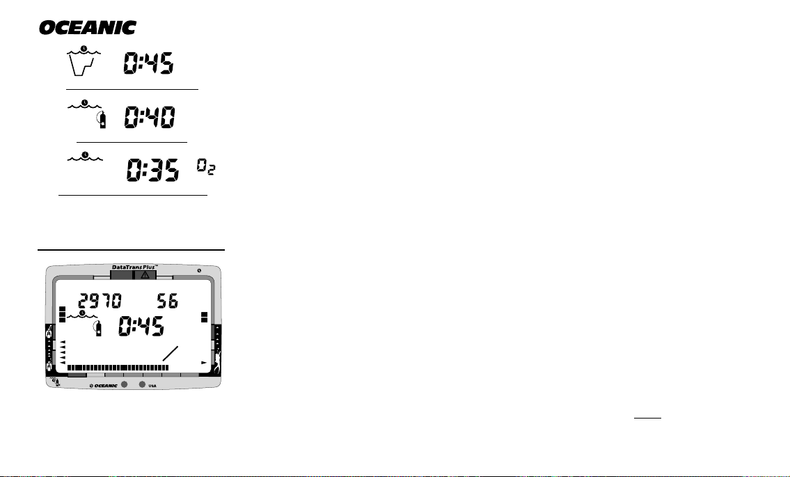
Knowing that you have 45 minutes of no decompression time remaining is not
as critical as knowing that you only have 40 minutes of breathing gas time remaining. Or, knowing that you have 40 minutes of breathing gas time remaining is not as critical as knowing that you only have 35 minutes of oxygen accumulation time remaining. The DataTrans Plus presents the dive time remaining that is considered to be of primary importance. This unique feature of select Oceanic dive computers has been granted U.S. Patent No. 4,586,136.
Breathing Gas Time Remaining
5
10
30
0
20
®
Fig. 13 - Breathing Gas
Time Remaining
12
a
Breathing Gas Time Remaining will appear as the numeric Dive Time Remaining display (Fig. 13) only when it is less than No Decompression Time Remaining and Oxygen Accumulation Time Remaining. Breathing Gas Time Remain-
60
40
50
ing of 60 minutes, or less, will be displayed continuously as the Gas Time Remaining Bar Graph (Fig. 13a) regardless of which time is being displayed as
the numeric Dive Time Remaining. The bar graph represents only Breathing
Gas Time information and it will be the only indication of breathing gas time
Page 25

remaining if you are in a decompression or violation mode.
The DataTrans Plus calculates Breathing Gas Time Remaining using a pat-
ented algorithm that is based on a diver's individual breathing gas consumption rate and depth. Tank pressure is measured once each second, and an average rate of consumption is calculated over a 90 second period. This rate of
consumption is then used in conjunction with a knowledge of the depth dependence to predict the breathing gas required for a safe ascent including any required decompression stops.
Breathing gas consumption and depth are continuously monitored, and
Breathing Gas Time Remaining reflects any change in your circumstances.
For example, when a buddy starts breathing from your octopus or you suddenly find yourself swimming against a strong current and begin breathing
more rapidly, the DataTrans Plus will recognize this change and adjust your
Breathing Gas Time Remaining accordingly.
DataTrans Plus
Remember, the Breathing Gas Time Remaining is the time you can remain at
the present depth and still surface with the tank pressure reserve (Gas Alarm
Set Point) that you set during setup. When Gas Time Remaining indicates
zero, you should immediately initiate a controlled ascent. However, there is no
reason to panic, the DataTrans Plus has allowed for the breathing gas necessary for a safe ascent including any emergency decompression stops.
R
E
S
P
O
N
R
E
V
I
D
E
S
L
I
B
13
Page 26

®
No Decompression Dive Time Remaining
No Decompression Dive Time Remaining is the maximum amount of time that
you can stay at your present depth before entering a decompression situation.
It is calculated based on the amount of nitrogen absorbed by twelve hypothetical tissue compartments. The rates each of these compartments absorb and
release nitrogen is mathematically modeled and compared against a maximum
allowable nitrogen level. Whichever one of the twelve is closest to this maximum level is the controlling compartment for that depth. Its resulting value
will be displayed numerically along with the No Decompression Dive icon and
graphically as the Tissue Loading Bar Graph (Fig. 14).
NO DECO
0
5
C.Z. C.Z.
DECO
PSI
10
30
20
®
O
2
FT
60
40
50
Fig. 14 - No Decompression
Dive Time Remaining
14
As you ascend from depth following a dive that has approached the no decompression limit, the Tissue Loading Bar Graph will diminish as control shifts to
slower compartments. This is a feature of the decompression model that is the
basis for multilevel diving, one of the most important advantages the
DataTrans Plus offers. See the Reference section for more information pertaining to tissue tracking.
The no decompression algorithm is based upon Haldane’s theory using maximum allowable nitrogen levels developed by Merrill Spencer. Repetitive diving
control is based upon experiments designed and conducted by Dr. Ray Rogers
and Dr. Michael Powell in 1987. Diving Science and Technology® (DSAT), a
corporate affiliate of PADI®, commissioned these experiments and now uses
Page 27

the findings in the Recreational Dive Planner™ distributed by PADI.
Oxygen Accumulation Time Remaining
Oxygen accumulation (exposure) during a dive, or 24 hour period, appears
graphically as the O2 Bar Graph. As time remaining before reaching the oxygen exposure limit decreases, segments are added to the O2 bar graph. When
the amount of time remaining before reaching the oxygen limit becomes less
than the No Decompression Dive Time Remaining or Breathing Gas Time Remaining, calculations for the dive will be controlled by oxygen. Oxygen Time
Remaining will then appear as the main numeric time display (Fig. 15a) as signified by the O2 symbol appearing to the right of the display.
As oxygen accumulation continues to increase, the O2 bar graph will enter the
yellow Caution Zone. High O2 Mode is explained in detail in the Handling the
Extremes section.
ALPHA/NUMERIC DISPLAYS
DataTrans Plus
DECO
a
O
2
PSI
FT
b
NO DECO
C.Z. C.Z.
R2
Cylinder Pressure Display
The Cylinder Pressure display, located in the upper/left portion of the screen
(Fig. 15b), indicates how much breathing gas is in your cylinder, up to 5000
PSI (352 BAR) to nearest 10 PSI (.5 BAR).
5
10
30
0
20
®
60
40
50
Fig. 15 - Oxygen Accumula-
tion Time Remaining
15
Page 28
®
The value of pressure will be displayed during all dive modes when the Display
Module is linked to the Transmitter and within the operating range. Linking
is explained in more detail in the Pre Dive and Dive Mode section.
Depth Displays
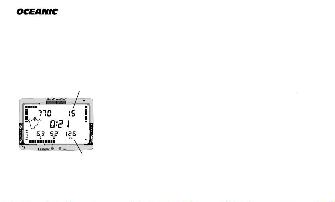
During a dive, the Current Depth display, located in the upper/right portion
of the screen (Fig. 16a), indicates depths from 0 to 330 feet (99.5 meters) in 1
foot (.5 meter) increments.
C.Z. C.Z.
NO DECO
0
DECO
PSI
5
10
40
30
20
®
Fig. 16 - Depth Displays
(Alternate Dive Mode)
16
a
O
2
FT
The value of current depth will be displayed during all dive modes unless you
descend deeper than 330 feet (99.5 meters), at which point the display will
show three dashes ( - - - ) to indicate that you have gone 'out of range'. This is
described in detail in the Handling the Extremes section.
A second depth display located in the lower/right portion of the LCD (Fig. 16b)
indicates the Maximum Depth reached during that dive. If the Alternate
Mode is turned 'off', the display will appear when the Select/Right button is
60
50
pressed. More critical information such as a message will override it.
b
In the event that you descend deeper than 330 feet (99.5 meters), this display
will only show three dashes ( - - - ) as the maximum depth for the remainder of
that dive, and as the Max Depth in the Dive Log for that dive. This is described in detail in the Handling the Extremes section.
Page 29
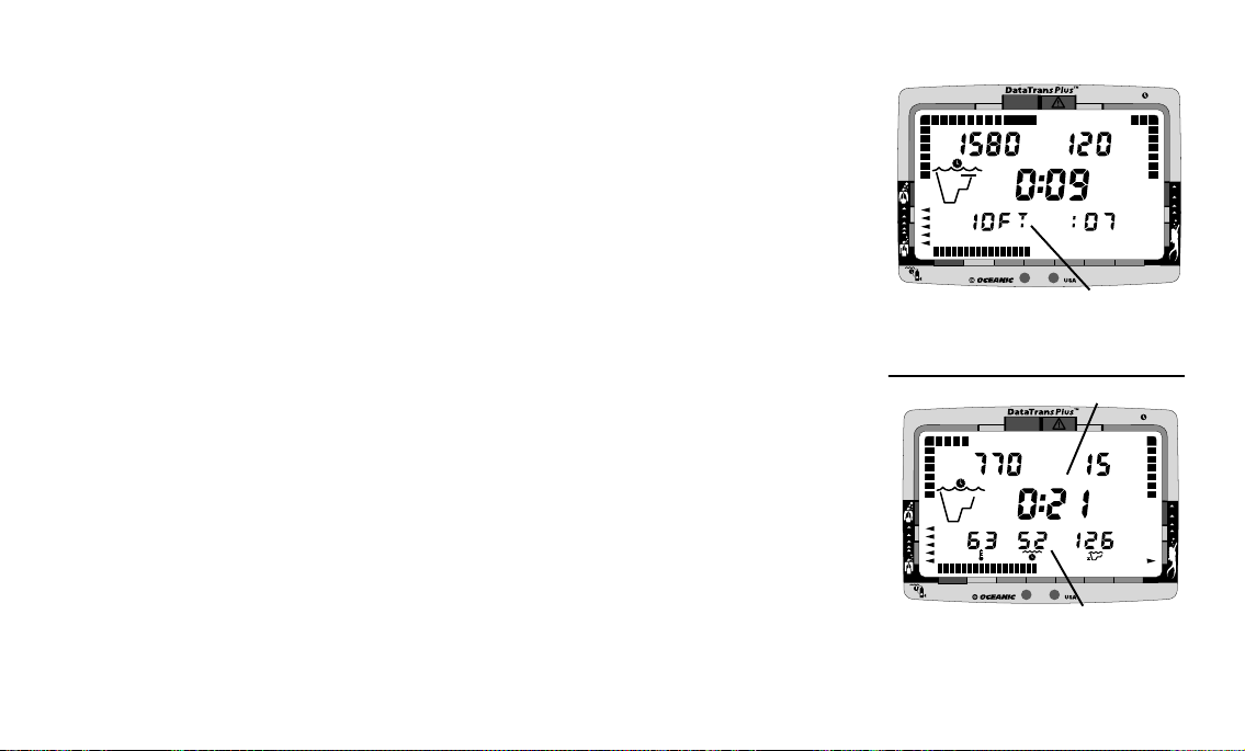
During a Decompression Dive the required Ceiling Stop Depth appears in
the lower/left portion of the screen (Fig. 17a). The display toggles with the
message CEILING once every 15 seconds while in the Decompression Mode.
This is described in detail in the Handling the Extremes section.
Time Displays
DataTrans Plus
NO DECO
C.Z. C.Z.
DECO
PSI
O
2
FT
R2
The Main Time display, located in the center of the screen (Fig. 18a), has
larger digits than the other numerial displays. Depending on the operating
mode that the DataTrans Plus is in at the time, the display indicates elapsed
Surface Time, theoretical Dive Time Available, Dive Time Remaining, or Total
Ascent Time required.
A second Time display appears in the lower portion of the screen. Depending
on the operating mode that the DataTrans Plus is in at the time, the display
indicates Elapsed Dive Time (Fig. 18b), Decompression Stop Time required,
Time of Day, or Time to Fly.
Each display is described in detail in subsequent sections of this owner's guide.
Most of the time displays are shown in hour:minute format (i.e. 1:02 repre-
sents one hour and two minutes, not 102 minutes!). The colon that separates
hours and minutes blinks once per second when the display is indicating real
time such as elapsed Surface Time. Dive Time Available, No Decompression
5
10
30
0
20
®
60
40
50
b
Fig. 17 - Depth Displays
(Decompression Dive Mode)
a
NO DECO
0
5
C.Z. C.Z.
DECO
PSI
10
30
20
®
O
2
FT
60
40
50
b
Fig. 18 - Time Displays
(Alternate Dive Mode)
17
Page 30

®
Dive Time Remaining, Total Ascent Time required, or Time to Fly are calculated projections of time and use a solid (non-blinking) colon to indicate that
they are counting down, rather than counting up.
Elapsed Dive Time, that appears in the lower/center portion of the display
(Fig. 19a) when the Alternate Mode is turned 'on', is in minute format with a
maximum display value of 99 minutes. If the Alternate Mode has been turned
'off', Elapsed Dive Time can be displayed by depressing the Select/Right button.
Ambient Temperature Display
NO DECO
0
5
C.Z. C.Z.
DECO
PSI
10
30
20
®
b
O
2
FT
60
40
50
a
Fig. 19 - Alternate Dive Mode
18
When the Alternate Mode is turned 'on', ambient Temperature will appear in
the lower/left portion of the display(Fig. 19b). If the Alternate Mode has been
turned 'off', Temperature can be displayed by depressing the Select/Right button.
NOTE: More critical information such as Ceiling Stop Depth
required or a message will override the lower displays.
Responsible
Page 31

AUDIBLE ALARM
When you are approaching dangerous situations, the DataTrans Plus alerts
you to check the Message Box, Graphic Diver Interface, and numeric displays.
There are four Audible Alarms.
Potential Danger – One Double Beep
During situations that may pose potential danger, one Double Beep is emitted
from the DataTrans Plus. These situations are as follows:
• Entry into decompression.
• Decreasing to 5 minutes of Breathing Gas Dive Time Remaining.
• Partial pressure of oxygen equal to or greater than 1.40 ATA.
Immediate Danger – continuous One Beep per Second
DataTrans Plus
BEEP!
BEEP!
(Potential Danger)
When the DataTrans Plus senses immediate danger to you, it emits One Beep
per Second until one of the following situations is corrected:
• Descent deeper than the Depth Alarm Set Point.
• Continuous interruption of signal link of more than 60 seconds.
• Ascent to a depth shallower than a required stop depth.
BEEP...
BEEP...
BEEP...
(Immediate Danger)
19
Page 32

®
• Ascent rate that exceeds 60 ft./min (18 m/min).
• Gas Time Remaining equals required Decompression time.
• Gas Time Remaining equals zero (0:00).
• Partial pressure of oxygen equal to or greater than 1.60 ATA.
• Oxygen accumulation greater than the allowed per dive or 24 hour limit.
Permanent Violations – Single Long Beep
If you enter a Delayed or Immediate Violation Mode, a Single Long Beep will
be emitted. This will occur if one of these Violation rules are broken:
20
BEEEEEEP!
(Violation)
BEEP!
(Transition)
• Depth is shallower than the required stop depth for more than 5 minutes.
• Required Decompression exceeds a 60 FT/ 18 M ceiling.
Transition – Short Beep
To indicate that a command has been accepted, the DataTrans Plus will emit a
Short Beep whenever you use the control console, and immediately following
activation and the Diagnostic Mode.
Page 33

MESSAGE BOX
The Message Box, located in the lower portion of the screen (Fig. 20), provides
a visual explanation of what is occurring when the audible alarm sounds,
working in conjunction with the Depth and Gas Alarm Set Points, as well as
Decompression and Violation Modes, and the Variable Ascent Rate Indicator.
Messages such as, “TOO FAST”, “GAS ALARM”, and “VIOLATION” flash on
the display in the language that you set. This is described in detail in the Handling the Extremes section. Also, a language cross reference is provided on
page 118 for your convenience.
BACKLIGHT FEATURE
DataTrans Plus
C.Z. C.Z.
NO DECO
0
DECO
5
10
30
20
®
Fig. 20 - Message Box
O
2
60
40
50
In addition to using a high contrast LCD for easy readability in low light conditions, the DataTrans Plus Oceanglo™ backlight feature evenly and easily illuminates the full display (Fig. 21). This means that on night dives, in caves, or
any other low light situation, you illuminate the display when you wish to view
it with the touch of a button.
Upon activation the Oceanglo™ backlight will illuminate the display while the
unit performs its diagnostic check. To activate the backlight during the Dive
mode, simply press the Advance/Left control button. Oceanglo will remain illuminated as long as the button is depressed, plus 10 seconds after being re-
DECO
20
®
PSI
304050
O
2
FT
60
NO DECO
0
C.Z. C.Z.
5
10
Press
Fig. 21 - Backlight
(Oceanglo™)
21
Page 34

®
140°F (60°C)
NO DECO
0
2
DECO
FT
PSI
5
60
10
304050
20
®
O
C.Z. C.Z.
32°F (0°C)
Fig. 22 - Operating
Temperature Range
leased (for a maximum of 15 seconds).
Oceanic recommends that you always carry primary and backup dive
lights when conducting dives that could include low light situations.
OPERATING TEMPERATURE
The DataTrans Plus will operate in almost any temperature diving environment in the world (Fig. 22) between 32 and 140°F (0 and 60°C). At extremely
low temperatures, the LCD may become sluggish, but this will not affect it's
accuracy. If stored or transported in extremely low temperature areas (below
freezing), you should warm the module and its batteries with body heat before
diving.
Even though the DataTrans Plus will operate in this wide range of temperatures, it is possible to damage the electronics if left exposed to direct
sunlight, or in a hot confined space (like a car trunk). After the dive,
cover the Display Module and keep it out of the sun. If inadvertently left in
the direct sunlight for a long period, the LCD display may become totally
black. If this occurs, immediately immerse the Display Module in water. The
display should recover its normal appearance after a few minutes. Damage
from excess heat, or cold, is not covered by the DataTrans Plus two
year limited warranty.
22
Page 35

SHARING THE DATATRANS PLUS
WARNING: Never participate in sharing or swapping of a dive
computer. Doing so may result in injury or death.
The DataTrans Plus provides information based upon a diver’s personal dive
profile, and therefore must not be “shared” between divers. You should
never, under any circumstances, swap your computer with another unit between dives, or share your computer with another diver underwater. It is impossible for two divers to stay precisely together underwater, and your
computer's dive profile tracking of previous dives will be pertinent to
you only. Nitrogen and oxygen loading of a second user may be significantly
different and thus swapping dive computers could lead to inaccurate and potentially dangerous predictions of decompression and oxygen accumulation
status. This rule applies to the use of all dive computers, but is especially important when using the DataTrans Plus, due to the personal information it
provides.
DataTrans Plus
R
E
S
P
O
N
R
E
V
I
D
E
S
L
I
B
23
Page 36

®
NO DECO
b
C.Z. C.Z.
DECO
PSI
BAR
O
MAX
FT
M
2
c
h
g
Key:
a - Gas Consumption Indicator
b - Tissue Loading Bar Graph
c - O2 Accumulation Bar Graph
d - Variable Ascent Rate Indicator
e - Gas Time Remaining Bar Graph
f - Transmitter Link icon
g - Operating mode icon (detail A)
h - Oxygen mode symbol
i - Low Battery icon (detail B)
j - Maximum Depth icon
k - Elapsed Dive Time icon
l - Temperature icon
m - PC Interface sensors
i
a
d
f
5
0
l
Fig. 23 - Graphic Interface
Legend
24
10
20
30
®
40
50
60
e
k
m
j
Page 37

DataTrans Plus
ACTIVATION
and
SETUP
25
Page 38

®
MAKING THE DATATRANS PLUS PERSONAL
Before you dive with the DataTrans Plus for the first time, you will need to become acquainted with its interactive features, and select your personal display
settings using the Control Console and Mode Menu.
Fig. 24 - Standard
First Stage
Fig. 25 - DX3 Integrated
First Stage
26
The transmitter must first be installed into a high pressure port of your regulator first stage, facing to one side (Fig. 24) - unless you purchased the DX3
™
Integrated first stage in which the transmitter is a built-in component (Fig.
25). Oceanic strongly recommends that installation be performed by an Authorized Oceanic Dealer at the time of purchase. If this is not possible, refer to
the instructions for this procedure on page 102.
NOTE: The DataTrans Plus transmitter is compatible with all
Oceanic first stages, but cannot be guaranteed to fit certain
models produced by other manufacturers. Check with your Authorized Oceanic Dealer to verify compatibility with your regulator first stage.
For the Display Module to receive a tank pressure signal from the Transmitter, the two devices must first be 'Linked'. The code (serial number) of the
Transmitter must be entered as the 'Link' code in the Display Module.
Page 39

If your Display Module and Transmitter were packaged and shipped from the
®
DECO
C.Z. C.Z.
PSI
BAR
M
FT
O
2
NO DECO
0
5
10
20
30
40
50
60
MAX
factory as a complete system, the code of your Transmitter has already been
entered as the 'Link' code in your Display Module. If the two units have been
purchased separately by you or your Authorized Oceanic Dealer, it will be necessary to set the Link code in the Display Module so that a tank pressure signal can be received. If the Display Module has been purchased as a stand
alone computer without the Transmitter, it has been preset at the factory as a
non-linked unit, but can easily be reset at any time to 'Link' with a Transmitter code (serial number) using the Control Console.
ACTIVATING THE DISPLAY
Before activating the Display Module, the regulator containing the transmitter
R2
must be connected to a full tank and pressurized by slowly opening the tank
valve. Tank pressure of 50 psi (3.5 BAR ), or greater, is required for the transmitter to activate. Position the display module within 3 feet (1 m) of and parallel to the transmitter (Fig. 26), and hold it in this location during activation.
WARNING: Never activate the DataTrans Plus underwater.
This may result in inaccurate depth and no-decompression time
displays. If activated deeper than 4 feet (1 meter) underwater a
message "TOO DEEP" will appear and the unit will shut off.
DataTrans Plus
Fig. 26 - Positioning
During Activation
27
Page 40

R2
®
C.Z. C.Z.
NO DECO
0
DECO
PSI
BAR
5
10
40
30
20
®
50
Fig. 27 - Diagnostics
in Progress
C.Z. C.Z.
NO DECO
0
DECO
PSI
5
10
40
30
20
®
50
Fig. 28 - Diagnostics
Successfull
MAX
FT
M
FT
To activate the Display Module, press the Select/Right button once and release.
O
2
R2
The DataTrans Plus will immediately enter Diagnostic Mode, displaying all
“8’s”, followed by “dashes”, and then a countdown from 9 to 0 (Fig. 27). The
Message Box will read SELF - TEST and the Oceanglo backlight will illuminate the display throughout the diagnostic check. A single beep will be emitted to indicate successful completion of the operation.
60
While conducting diagnostics, the DataTrans Plus checks its display functions,
coded frequency link to the transmitter, and battery voltage to ensure that everything is working correctly.
If the Display Module is already set to the Transmitter's link code, the Link
O
2
icon will disappear from the screen and tank pressure will be displayed numerically (Fig. 28).
It will also check the ambient barometric pressure, and calibrate its present
depth as zero. At elevations of 2,000 ft. (610 m) or higher, it will recalibrate
itself to measure depth in feet of fresh water instead of feet of sea water.
60
28
Page 41

During the diagnostic mode, battery voltage level of both the Display Module
and the Transmitter are measured to determine if sufficient voltage is available to maintain operation for one day of diving. If there is not enough battery
voltage in the Display Module, it will deactivate itself or would not have activated at all. If there is not sufficient voltage in the Transmitter, the Link icon
and a tank pressure of "00" PSI will flash on display (Fig. 29). This could also
indicate one of the following conditions:
• The Transmitter was not pressurized prior to activation of the Display
Module.
• The Display Module was not positioned in close proximity to the Transmitter during activation, or not correctly positioned parallel to it.
• The Display Module is not linked to the same coded frequency as the
Transmitter.
If the Display Module is out of the range of the Transmitter while in Surface
Mode, the flashing will stop and the Link icon will disappear within 5 seconds
when the Display Module is returned to its correct proximity to the Transmitter.
R2
In the latter case, it will be necessary to follow the prescribed linking procedure outlined on page 41 to set the Display Module to the Link code that
matches that of the Transmitter's serial number, or to set a specific link code
that will allow the Display Module to function as a stand alone unit.
DataTrans Plus
C.Z. C.Z.
NO DECO
0
DECO
PSI
5
10
30
20
®
Fig. 29 - Unsuccessful Link
O
2
FT
60
40
50
29
Page 42

®
R
E
S
P
O
N
R
E
V
I
D
E
S
L
I
B
Be a -
RESPONSIBLE DIVER
at all times.
Low Battery conditions and battery power conservation are described in more
detail in the Care & Maintenance section.
WARNING: If either or both of the Low Battery icons remain
on display following diagnostics, Oceanic strongly recommends
that you DO NOT dive until the batteries are replaced. See the
battery replacement procedure on page 99.
If no dive is made within 2 hours after initial activation, the Display Module
will automatically deactivate to conserve its battery power. Check your Display Module before entering the water to verify that it is functioning and
doesn’t need reactivation.
To save its battery power while on the surface, the Display Module will stop
searching for a Transmitter signal after 10 minutes. The signal Link can be
restored by depressing the Select/Right button on the Display Module. It will
also be restored automatically upon descent on a dive.
WARNING: During activation and diagnostics, if any display or
message varies from the information presented here, return the
DataTrans Plus to your Oceanic Dealer for inspection.
30
Page 43

SURFACE MODE
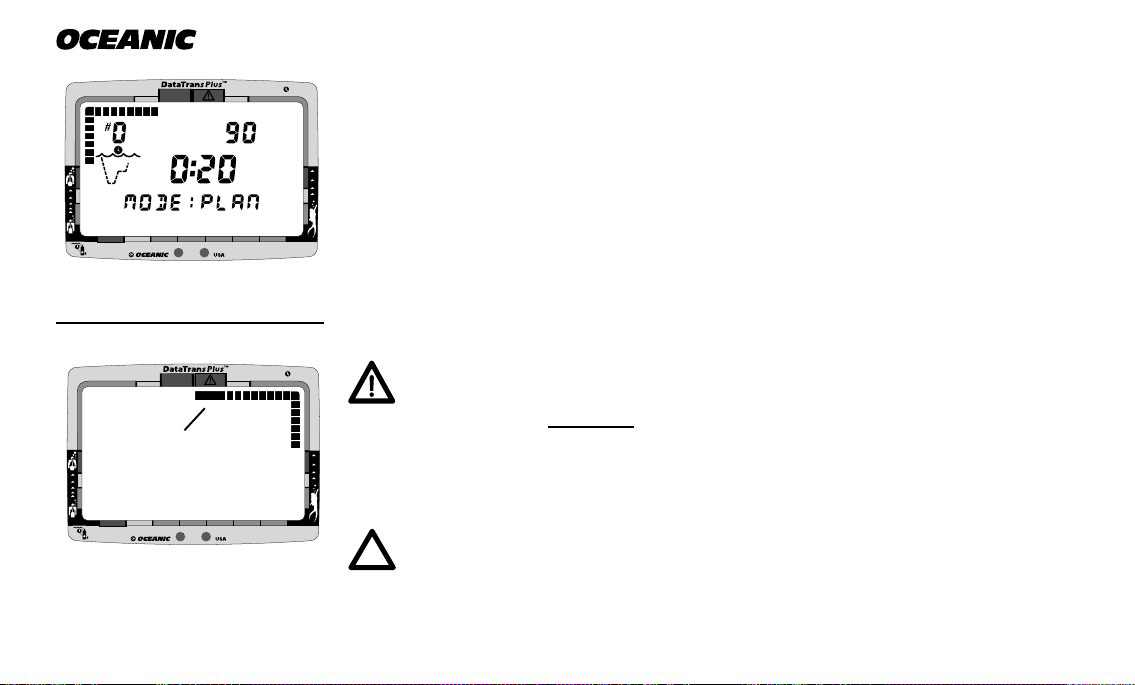
Surface Mode immediately follows Diagnostic Mode after initial activation
(Fig. 30), or after the linking procedure has been performed. It also appears
after a dive when you ascend shallower than 3 feet (1 meter). Surface Mode is
identified by the Surface Time icon. Information displayed includes Tank
Pressure, Depth (00 FT), Surface Time with flashing colon, Temperature, and
Time of Day with colon flashing.
MODE MENU SYSTEM
The Mode Menu system allows you to set the various display options that will
make the DataTrans Plus your personal computer. If you followed the Linking
procedure, you have already developed a feel for how the Control Console
works. The Advance/Left button is used to move through the Mode Menu and
change each setting, and the Select/Right button is used to select (enter) the
mode or setting that is currently on the screen. A brief glossary and hierarchy
of the menu system is as follows:
DataTrans Plus
NO DECO
C.Z. C.Z.
DECO
PSI
O
2
FT
Mode - Each mode provides a different display of information, or access to a
submenu or setting. Some modes, such as Dive Mode and Surface Mode, are
entered into automatically after activation. Others, such as the FO2 Mode,
Plan Mode and Alternate Dive Mode, are accessed using the Control Console,
when you want to view specific information.
5
10
30
0
20
®
60
40
50
Fig. 30 - Surface Mode
31
Page 44

®
Menu - The main menu allows interactive access from the Surface Mode to
various other modes used while on the surface.
Settings - These are display options (settings) that are determined by you before going diving. For example, with 'alarms' you can set the values at which
depth and tank pressure will alert you when you are going too deep or running
low on breathing gas.
32
Responsible
Mode Menu Sequence
• Surface
• FO2
• Plan
• Log
• History
• Set
• External Access
Settings Sequence
• Time
• Date
• Alternate
• Unit
• Alarms
• Link
• Language
NOTE: If the DataTrans Plus is left unattended for five minutes while in the Mode Menu, it will automatically revert to
Surface Mode.
Page 45

ENTERING SETTINGS
®
0
5
10
20
304050
60
®
0
5
10
20
30
40
50
60
Before going diving, enter the general settings to be used for each of your
dives. These include - Time, Date, Alternate Display, Units of Measure, Depth
Alarm, Gas (tank pressure) Alarm, Link code, and Language.
Note that FO2 is a 'pre dive' setting that must be entered prior to each nitrox
dive. Setting the FO2 value for the nitrox mixture being used is described in
the Pre Dive and Dive Mode section.
Set Time
Your DataTrans Plus has been factory set for 12:00 AM. To change to the current Time, follow this procedure, beginning in Surface Mode:
DataTrans Plus
Fig. 31 - Set Mode
1. Press the Advance/Left button 5 times to advance to the Set Mode.
MODE:SET will appear, with SET flashing (Fig. 31). If you accidentally
pass the Set Mode, you will need to press the Advance/Left button repeatedly until MODE:SET reappears.
2. Press the Select/Right button to select (enter) the Set Mode. SET:TIME
will appear, with TIME flashing (Fig. 32).
3. Press the Select/Right button once to select (enter) the Time setting.
Time of day will appear, with the first digit flashing (Fig. 33).
4. To set the time, press the Advance/Left button to change that digit until
Fig. 32 - Set Time
5
10
0
40
30
20
®
50
Fig. 33 - Time of Day
60
33
Page 46

®
it matches that of the current time, and press the Select/Right button to
save the digit shown and move on to the next.
5. Press the Advance/Left button to toggle between AM or PM, and press
the Select/Right button to save the one displayed.
After the time has been set, SET:DATE will appear with DATE flashing. To
5
10
304050
0
20
®
60
set the date, continue with step 4 of the following Set Date procedure, or to return to the Surface Mode press the Advance/Left button 6 times.
Set Date
R2
Fig. 34 - Set Date
5
10
0
20
®
Fig. 35 - Set Month
34
Your unit has been factory set for JAN 1 96. To change to the current Date,
follow this procedure, beginning with step 1 if in Surface Mode; or beginning
with step 4, if you just set the Time:
1. Press the Advance/Left button 5 times to advance to the Set Mode.
2. Press the Select/Right button to select the Set Mode.
3. Press the Advance/Left button 2 times to advance to the Date setting.
SET:DATE will appear, with DATE flashing (Fig. 34).
60
40
30
50
4. Press the Select/Right button to select the Date setting. The date will appear, with the month flashing (Fig. 35).
5. To set the Date, press the Advance/Left button to change the month, and
ress the Select/Right button to save it. Repeat for the day and year.
Page 47

After the year has been set, SET: ALT will appear, with ALT flashing. To set
®
0
5
10
20
30
40
50
60
the Alternate display continue with step 4 of the following Set Alternate Display procedure, or to return to the Surface Mode press the Advance/Left button 5 times.
Set Alternate Display
Your unit has been factory set so the values of Temperature, Elapsed Dive
Time, and Maximum Depth will be displayed continuously during the Dive
Mode. You can turn this Alternate display 'off' and have them appear only
when you wish to see them by depressing the Select/Right button during the
dive. To turn the Alternate Display 'off', follow this procedure, beginning with
step 1 if in the Surface Mode, or beginning with step 4 if you just set the Date:
1. Press the Advance/Left button 5 times to advance to the Set Mode.
2. Press the Select/Right button to select the Set Mode.
3. Press the Advance/Left button 3 times to advance to the Alternate setting. SET: ALT will appear with ALT flashing (Fig. 36).
4. Press the Select/Right button to select the Alternate Display setting.
ALT: ON will appear with ON flashing (Fig. 37).
5. Press the Advance/Left button to toggle between ON and Off, and press
the Select/Right button to select the one displayed.
DataTrans Plus
Fig. 36 - Set Alt
5
10
30
0
20
®
60
40
50
After the Alternate display has been set, SET:UNITS will appear with UNITS
flashing. To set the Units of Measure continue with step 4 of the following Set
Fig. 37 - Alt On/Off
35
Page 48

®
Units of Measure procedure, or to return to the Surface Mode press the Advance/Left button 4 times.
Set Units of Measure
5
10
0
Fig. 38 - Set Units
C.Z. C.Z.
NO DECO
5
10
0
Fig. 39 - Units
36
20
DECO
20
®
60
40
30
®
50
You can choose between Imperial (PSI and Feet) and Metric (BAR and Meters)
units of measure. Your unit has been factory set for FT and PSI. To change to
metric units of measure, follow this procedure, beginning with step 1 if in the
Surface Mode, or beginning with step 4 if you just set the Alternate Display:
1. Press the Advance/Left button 5 times to advance to the Set Mode.
R2
2. Press the Select/Right button to select the Set Mode.
3. Press the Advance/Left button 4 times to advance to the Unit setting.
O
2
PSI
FT
SET:UNIT will appear, with UNIT flashing (Fig. 38).
4. Press the Select/Right button to select the Unit setting. PSI and FT will
appear, flashing (Fig. 39).
5. Press the Advance/Left button to toggle between Imperial and Metric
units, and press the Select/Right button to accept the one displayed.
After the Units have been set, SET:ALRM will appear with ALRM flashing.
60
40
30
50
To set the alarm values continue with step 4 of the Set Gas and Depth Alarm
procedure beginning on page 40, or to return to the Surface Mode press the
Advance/Left button 3 times.
Page 49

BREATHING GAS & DEPTH ALARM SET POINTS
®
DECO
C.Z. C.Z.
PSI
FT
O
2
NO DECO
0
5
10
20
30
40
50
60
™
After planning each dive according to the no-decompression dive
times shown to be available in the Pre Dive Planning Sequence, Oceanic strongly recommends that you utilize one of the greatest safety
features the DataTrans Plus offers - the Gas & Depth Alarm settings.
While the DataTrans Plus uses the Audible Alarm, Message Box, and
Graphic Diver Interface to automatically alert you whenever you enter a potentially dangerous situation, such as Decompression Dive
Mode, ascending too fast, running low on breathing gas, etc., the
Alarm settings allow you to preset more conservative limits to better
avoid these situations.
DataTrans Plus
Depth Alarm Set Point
™
The Depth Alarm will alert you whenever you reach or exceed the maximum
depth Set Point value that you have chosen. Of course, if you set the Depth
Alarm for a depth that is deeper than the no-decompression or decompression
limits for that dive, you will first be alerted by other built-in alarms that you
have exceeded those limits before the Depth Alarm is activated.
When the Depth Alarm is activated by reaching or exceeding your preset maximum depth, the audible alarm will sound once per second, while the Message
Box flashes the words “TOO DEEP” (Fig. 40) until you ascend above the
Fig. 40 - Too Deep Message
(60 FT Set Point)
37
Page 50

®
Depth Alarm Set Point value. The Depth Alarm value may be set for depths
ranging from 30-320 feet (9-97.5 meters), in 10 foot (3 & 3.5 meter) increments. The setting that you choose for the Depth Alarm does not change the
displayed limits of no-decompression dive time remaining.
NO DECO
0
5
C.Z. C.Z.
DECO
PSI
10
30
20
®
O
2
FT
60
40
50
Fig. 41 - Gas Alarm Message
38
Breathing Gas Alarm Set Point
™
The Breathing Gas Alarm is an acoustic alert that indicates you are approaching a critical Breathing Gas Time Remaining. The Breathing Gas Alarm Set
Point refers to the surfacing tank pressure reserve of your choice, which may
be set for tank pressures ranging from 300 to 1000 psi (21 to 70 bar).
You will recall that Breathing Gas Time Remaining is the time that you can
remain at your present depth and, following a safe ascent, still surface with a
prescribed breathing gas reserve (identified here as the Breathing Gas Alarm
Set Point).
When your Breathing Gas Time Remaining reaches 5 minutes, the Gas Alarm
will emit a double beep as a preliminary warning. If you allow your Breathing
Gas Time Remaining to decrease to zero, the tank pressure display will flash
and the Message Box flashes the words "GAS ALARM" (Fig. 41) until you ascend to a depth of 5 feet (1.5 meters) or less.
While an immediate safe ascent is called for if the Breathing Gas Time Re-
Page 51

maining decreases to zero, there is no reason to panic. The DataTrans Plus
®
DECO
C.Z. C.Z.
FT
O
2
NO DECO
0
5
10
20
30
40
50
60
®
0
5
10
20
30
40
50
60
has allowed for the breathing gas you will consume during a safe ascent, including decompression stops if they are required, and still provide the tank
pressure reserve you have chosen, e.g., 300 psi (21 bar).
Set Depth and Breathing Gas Alarms
Your DataTrans Plus alarms have been factory set for 320 FT and 300 PSI.
These set point values will be retained unless you change them.
To set your desired Depth and Breathing Gas Alarm values, or turn the audible alarm off, follow this procedure, beginning with step 1 if in the Surface
Mode, or beginning with step 4 if you just set Units of Measure:
1. Press the Advance/Left button 5 times to advance to the Set Mode.
2. Press the Select/Right button to select the Set Mode.
3. Press the Advance/Left button 5 times to advance to the Alarm setting.
SET:ALRM will appear, with ALRM flashing (Fig. 42).
4. Press the Select/Right button to select the Alarm setting. The current
Depth Alarm Set Point value will appear, flashing (Fig. 43).
5. Press the Advance/Left button repeatedly to change the Depth Alarm Set
Point value to the depth you choose, and press the Select/Right button to
accept (save) that setting. The current Breathing Gas Alarm Set Point
DataTrans Plus
Fig. 42 - Set Alarm
Fig. 43 - Depth Alarm
39
Page 52

NO DECO
®
C.Z. C.Z.
DECO
PSI
value will appear, flashing (Fig. 44).
6. Press the Advance/Left button repeatedly to change the Breathing Gas
O
2
Alarm Set Point value to the pressure you choose, and press the Select/
Right button to save that setting. ALARM:ON will appear, with ON
flashing (Fig. 45).
7. Press the Advance/Left button to toggle between 'on' or 'off', and press the
Select/Right button to accept the one displayed.
5
10
0
20
®
Fig. 44 - Gas Alarm
C.Z. C.Z.
NO DECO
0
DECO
5
10
20
®
Fig. 45 - Alarm On
40
60
40
30
50
Turning Off the Audible Alarm
WARNING: Turning off the audible alarm disables an important tool that can help you avoid decompression diving or low
breathing gas emergencies. Although possible, Oceanic does
O
2
not recommend the disablement of the audible alarm.
The audible portion of the alarm may not be desired by some divers in
certain situations. Underwater photographers, for instance, may find
that the alarm frightens off marine life at a close distance, and will
therefore want to turn it off temporarily before they begin a dive involv-
60
40
30
50
ing that activity. For a reason such as this, the audible portion of the
alarm feature may be turned off at your discretion. The DataTrans Plus
will otherwise continue to display information according to the values
that have been entered for the Alarm settings.
Page 53

After the Alarm values have been set, SET:LINK will appear with LINK flashing. To set the Transmitter Link code continue with step 4 of the following
LINKING procedure, or to return to the Surface Mode press the Advance/Left
button 2 times.
LINKING PROCEDURE
Your DataTrans Plus Display Module has been factory set with the
Transmitter's serial number, or at serial number 999999 if no Transmitter was
purchased. If the DataTrans Plus linked automatically immediately following
activation, there is no need to perform the Linking procedure. However, if the
Link icon and pressure value of 00 PSI remained flashing on the screen, the
Linking procedure must be performed before the Display Module can receive
tank pressure data from the Transmitter.
The Linking procedure may also need to be performed in the event that your
DataTrans Plus Display Module or Transmitter has received factory service,
and is returned to you with a different Linking code. You may also choose to
“unlink” your Display Module from the Transmitter to use the Display Module
as a stand alone computer, without its pressure integrated features, or to link
it to a Transmitter that has been purchased separately at a time in the future.
To set the Display Module with the link code (serial number of the Transmitter), follow this procedure beginning with step 1 if in the Surface Mode, or be-
DataTrans Plus
R
E
S
P
O
N
R
E
V
I
D
E
S
L
I
B
41
Page 54

®
5
10
0
40
30
20
®
50
Fig. 46 - Set Link
5
10
0
40
30
20
®
Fig. 47 - Link Mode
ginning with step 4 if you just set the Alarms:
1. Press the Advance/Left button 4 more times to advance to the Set Mode.
60
2. Press the Select/Right button to select the Set Mode.
3. Press the Advance/Left button 6 times to advance to the LINK setting.
SET:LINK will appear, with LINK flashing (Fig. 46).
4. Press the Select/Right button to select the Link Mode (Fig. 47).
5. Compare the 6 digit serial number code shown on the display to the first
6 digits of the serial number embossed on the Transmitter.
a. If the numbers are the same, press the Select/Right button 6 times to ac-
cept (save) the code number shown. DO NOT press the Advance/Left
button, this will change the code to an incorrect number.
b. If the numbers are not the same, press the Advance/Left button to change
60
50
the first digit of the code as required, then press the Select/Right button
to save that digit. Repeat until all 6 digits are set correctly.
If you would like to set the Display Module to function as a stand alone, non
pressure integrated computer, use the control buttons as described above to
set the code as 999999 (Fig. 48).
5
10
0
20
®
Fig. 48 - Stand Alone
42
60
40
30
50
After the Link code has been set, SET:LANG will appear with LANG flashing.
To set your preferred Language continue with step 4 of the following Set Language procedure, or to return to the Surface Mode press the Advance/Left button once.
Page 55

Set Language
®
0
5
10
20
30
40
50
60
®
0
5
10
20
30
40
50
60
The Message Box displays warning messages in the language that you choose either English, Italian, German, Spanish, or French. The Mode Menu sys-
tem is also displayed in the language selected, so it is very important
that you do not accidentally change this setting to a language that
you do not understand.
Your unit has been factory set for English. To change the language, follow
this procedure beginning with step 1 if in the Surface Mode, or beginning with
step 4 if you just set the Link code:
DataTrans Plus
1. Press the Advance/Left button 4 more times to advance to the Set Mode.
Fig. 49 - Set Language
2. Press the Select/Right button to select the Set Mode.
3. Press the Advance/Left button 7 times to advance to the Language setting. SET:LANG will appear, with LANG flashing (Fig. 49).
4. Press the Select/Right button to select the Language setting. The default
setting ENGLISH will appear, flashing (Fig. 50).
5. Press the Advance/Left button to scroll through the Language setting options until you arrive at the one you prefer.
6. Be careful to ensure that the language selection flashing is the one that
you prefer before you press the Select/Right button.
7. Press the Select/Right button to save the Language chosen and return to
the Surface Mode.
Fig. 50 - Language
43
Page 56

NO DECO
®
C.Z. C.Z.
DECO
Language Correction Procedure
If you accidentally selected a language that you do not prefer or understand,
you may find it very confusing to navigate further in the Mode Menu or understand the Message Box warnings (Fig. 51). To correct the language, it is recommended that you wait 5 minutes to allow the Display Module to default to
the Surface Mode, then carefully perform the following procedure:
1. Press the Advance/Left button 5 times to arrive at the Set Mode.
2. Press the Select/Right button once to enter Set Mode.
3. Press the Advance/Left button 7 times to arrive at the Language submenu.
O
2
4. Press the Select/Right button once to select the Language submenu.
5. Press the Advance/Left button as needed until your preferred language
appears.
6. Press the Select/Right button to save the language chosen and return to
the Surface Mode.
5
10
30
0
20
®
Fig. 51 - Language
(Set: Link - German)
44
60
40
50
Responsible
Page 57

DataTrans Plus
PRE DIVE
and
DIVE MODES
45
Page 58

®
®
DECO
C.Z. C.Z.
PSI
FT
O
2
NO DECO
0
5
10
20
30
40
50
60
®
DECO
C.Z. C.Z.
PSI
FT
O
2
NO DECO
0
5
10
20
30
40
50
60
®
DECO
C.Z. C.Z.
PSI
FT
O
2
NO DECO
0
5
10
20
30
40
50
60
®
DECO
C.Z. C.Z.
PSI
FT
O
2
NO DECO
0
5
10
20
30
40
50
60
Poor reception distance.
(Greater than 3 feet)
Poor
reception
area.
Poor
reception
area.
46
Best
reception
zone.
Page 59

POSITIONING OF THE DISPLAY MODULE
The Transmitter emits a low frequency signal that radiates outward in a semicircular pattern that is parallel to the length dimension of the Transmitter. A
coiled antenna inside the Display Module receives the signal when it is positioned within a zone parallel to or at a 45 degree angle to the Transmitter as
shown on page 46. The Display Module cannot effectively receive the signal
when it is held out to the sides of the Transmitter, or held at distances greater
than 6 feet (2 meters) in front of the Transmitter. Best reception is achieved
when the Display Module is within 3 feet (1 meter) of the Transmitter.
DataTrans Plus
When installed into a high pressure port of your first stage regulator, the
Transmitter must be positioned so that it faces horizontally outward from the
tank valve.
LINK INTERRUPTION UNDERWATER
During a dive, you may at times move the Display Module out of the signal
pattern resulting in a temporary interruption of the link signal.
An interruption greater than 15 seconds will cause the Link icon and tank
pressure display to flash (Fig. 52). Also, an audible alarm will sound once per
second until the link is restored. The link will be restored within 4 seconds
NO DECO
0
5
C.Z. C.Z.
DECO
PSI
10
30
20
®
O
2
FT
60
40
50
Fig. 52 - Underwater Link
Interruption
R2
47
Page 60

Responsible
®
after the Display Module is moved back into its correct position.
An interruption may also occur while the Display Module is in an area 3 to 4
feet (1 meter) of a running dive propulsion vehicle. The link will be restored
within 4 seconds after the vehicle motor is shut off or when the Display Module is moved out of this area.
When using a photo strobe, temporary link interruption may occur shortly after the strobe flashes. The link will be restored in 4 seconds.
WARNING: During the period of link interruption, the Display
Module will temporarily loose transmitted pressure related
functions and displays. These will be regained 4 seconds after
the link is restored.
OPERATIONAL MODES
The DataTrans Plus operates in different operational modes, including the Diagnostic, Surface, and Set Modes which have already been explained in de-
tail in the previous section, “Activation & Setup.” This section describes the
modes that the DataTrans Plus operates in before and during a dive.
48
Page 61

FO2 MODE
®
0
5
10
20
30
40
50
60
WARNING: The percentage of oxygen (FO2) in the nitrox mix
being used must be set 'before each' nitrox dive.
The DataTrans Plus can be used either as an Air computer or a Nitrox computer. After activation, the Display Module will operate as an Air computer
without displaying information associated with oxygen calculations, unless it is
set for a percentage of oxygen (FO2) other than Air (numerical value between
21 and 50 %).
FO2 Set for Air
DataTrans Plus
Fig. 53 - FO2 Mode
If you are using 'Air' as your breathing gas, you can verify that 'Air' is the FO2
value by performing the following procedure beginning in the Surface Mode:
1. Press the Advance/Left button once to enter the Mode Menu. MODE:
FO2 will appear, with FO2 flashing (Fig. 53).
2. Press the Select/Right button once to select the FO2 Mode. FO2 Air will
appear, with Air flashing (Fig. 54).
3. Press the Select/Right once to accept Air as the setting. MODE:PLAN
will appear with PLAN flashing.
4. Press the Advance/Left button 5 times to return to the Surface Mode.
C.Z. C.Z.
NO DECO
0
DECO
5
10
40
30
20
®
Fig. 54 - Air Setting
O
2
60
50
49
Page 62

NO DECO
®
C.Z. C.Z.
DECO
PSI
When set with an FO2 value of 'Air', the DataTrans Plus will perform calcula-
O
2
tions the same as if FO2 were set for 21% oxygen, internally accounting for
oxygen loading for any subsequent Nitrox dives. However, oxygen related dis-
FT
plays, warnings, and the O2 bar graph will not appear on the LCD display for
that dive (Fig. 55), or subsequent dives, unless FO2 is set for a numerical value
(21 to 50 %).
5
10
0
40
30
20
®
Fig. 55 - Dive Mode (Air)
C.Z. C.Z.
NO DECO
0
DECO
5
10
40
30
20
®
Fig. 56 - FO2 Default
(after nitrox dive)
50
60
50
Setting FO2 for a Nitrox Dive
You can program the DataTrans Plus for nitrogen-oxygen (nitrox) mixtures of
21% to 50% oxygen (O2) before each nitrox dive. If FO2 is set at a value of
21%, the unit will remain set as a '21% nitrox computer' for subsequent nitrox
dives until FO2 is set to a higher value, or the Display Module automatically
O
2
turns off. Once FO2 is set to a value 'greater than 21%' to match the nitrox
mix being used for that nitrox dive, the FO2 value displayed during the FO2
Mode that is accessible 10 minutes after that dive will be 50% (Fig. 56).
FO2 must be reset for each repetitive nitrox dive, or the value will automatically default to 50 and the dives will be calculated based on 50% O2 for oxygen
60
50
calculations and 21% O2 (79% nitrogen) for nitrogen calculations. Once a dive
is made with the DataTrans Plus set as a nitrox computer (FO2 set for a numerical value), the unit cannot be programmed to operate as an 'Air' computer
until 24 hours after the last dive. 'Air' will not be displayed as an option in the
FO2 Mode.
Page 63

WARNING: The DataTrans Plus will default to an FO2 value of
®
DECO
C.Z. C.Z.
O
2
NO DECO
0
5
10
20
30
40
50
60
50 after a 10 minute surface interval following a nitrox dive.
Therfore, this procedure must be performed prior to descent on
each and every nitrox dive, even if the percentage of oxygen in
the nitrox mixtures used remains the same.
To set (enter) a numerical value for the percentage of oxygen (FO2) in your
nitrox mix, perform the following procedure beginning in the Surface Mode:
1. Press the Advance/Left button once to enter the Mode Menu. MODE:
FO2 will appear with FO2 flashing.
2. Press the Select/Right button once to select the FO2 Mode. If a previous
dive was made that day with the unit set for Air, FO2 and Air will appear,
with Air flashing. If a previous dive was made with the unit set for a numerical value of FO2, FO2 and 50 will appear, with 50 flashing.
3. Press and hold the Advance/Left button, or press it repeatedly, until the
proper value of FO2 appears (Fig. 57). The percentage displayed will advance 1 (%) per second from 21 to 50 (%), then display 'Air' again.
4. Once the proper value of FO2 is displayed, press the Select/Right once to
save the value shown as the setting for that dive. MODE:PLAN will appear with PLAN flashing.
5. Press the Advance/Left button 5 times to return to the Surface Mode.
DataTrans Plus
Fig. 57 - Setting FO2
51
Page 64

®
PLAN MODE
Oceanic strongly recommends that you access the Plan Mode prior to
every dive to review the Pre Dive Planning Sequence (PDPS) that
will help you plan your dive as required to avoid exceeding no decompression, or oxygen exposure limits. This is especially important for
repetitive dives, when the Pre Dive Planning Sequence will indicate for you
the adjusted no decompression bottom times that are available to you for your
next dive, based on any residual nitrogen or oxygen accumulation (whichever
is in control) following your last dive and surface interval.
WARNING: The Pre Dive Planning Sequence predicts only no
decompression times for subsequent dives. Depending on cylinder size, breathing gas consumption, and oxygen accumulation, you may have less time available than indicated because
of breathing gas quantity or other limitations.
5
10
0
20
®
Fig. 58 - Plan Mode
52
60
40
30
50
To access the Plan Mode, press the Advance/Left button twice beginning in the
Surface Mode. MODE:PLAN will appear, with PLAN flashing (Fig. 58). Press
the Select/Right button once to enter the Plan Mode.
If FO2 was set for 'Air', the PO2 screen will not appear and the DataTrans
Plus will begin to scroll through the Pre Dive Planning Sequence.
Page 65

If FO2 was set for a numerical value, FO2 and the value set will appear as the
®
DECO
C.Z. C.Z.
O
2
NO DECO
0
5
10
20
30
40
50
60
®
DECO
C.Z. C.Z.
FT
O
2
NO DECO
0
5
10
20
30
40
50
60
MAX
first screen (Fig. 59), followed by a screen showing the maximum depth that
can be achieved for an oxygen partial pressure of 1.60 ATA for that FO2 (Fig.
60).
The DataTrans Plus then scrolls through the Pre Dive Planning Sequence
(PDPS), displaying a sequence of depths from 30 to 160 feet (9 to 48 meters) in
10 foot (3 meter) increments. With each depth display, you will see either 'predicted' no decompression limits based upon your previous dive profiles (if calculated to be nitrogen controlled), or 'predicted' oxygen tolerance limits based
upon either a single dive oxygen dose or your 24 hour accumulation of oxygen
(if calculated to be oxygen controlled).
DataTrans Plus
Fig. 59 - FO2 Value Set
Information displayed includes Previous Dive #, Depth, Dive Time available at
that depth (which includes descent time at a rate of 120 ft/min), Plan Mode
icon, and the message MODE:PLAN.
No decompression times are only displayed for depths where there is at least 3
minutes of dive time available at the depth, taking into account a descent rate
of 120 feet (36 meters) per minute. Depths greater than the maximum depth
that can be achieved with a partial pressure of oxygen (PO2) of 1.60 ATA will
not be displayed.
R2
Fig. 60 - Max Allowed Depth
53
Page 66

NO DECO
®
C.Z. C.Z.
DECO
O
2
FT
After scrolling once through depth and dive times available, the DataTrans
Plus will automatically return to the Surface Mode. Plan Mode can be accessed and the sequence repeated as often as you choose. If you wish to interrupt the Pre Dive Planning Sequence to return to the Surface Mode, you may
do so at any time by pressing either control button.
Fig. 61 - Nitrogen Controlled
NO DECO
C.Z. C.Z.
DECO
O
2
FT
Fig. 62 - Oxygen Controlled
NO DECO
C.Z. C.Z.
DECO
O
2
Fig. 63 - Max Daily O2
Limit Exceeded
54
Prior to a Repetitive Nitrox Dive
If the segments of the Tissue Loading Bar Graph are displayed during the Pre
Dive Planning Sequence (Fig 61), that next dive is calculated to be controlled
by nitrogen loading.
If the segments of the O2 bar graph are displayed Pre Dive Planning Sequence
(Fig. 62), that next dive is calculated to be controlled by oxygen loading.
R2
The DataTrans Plus will store oxygen accumulation for up to 10 dives conducted during a 24 hour period. In the event that the maximum limit for oxygen loading has been exceeded for that day (24 hour period), all of the segments of the O2 bar graph will be displayed (Fig. 63). Depth and Time displays will not appear until the O2 bar graph recedes into the green (normal)
zone (i.e., your daily oxygen doseage decreases an amount equivalent to the
amount accumulated during the latest dive completed).
Page 67

WARNING: The DataTrans Plus must be manually activated
®
DECO
C.Z. C.Z.
PSI
FT
O
2
NO DECO
0
5
10
20
30
40
50
60
®
DECO
C.Z. C.Z.
PSI
FT
O
2
NO DECO
0
5
10
20
30
40
50
60
and be in an operating mode prior to start of a dive. The unit
will not activate automatically by immersion in water. Also,
FO2 must be set prior to commencing each nitrox dive.
NO DECOMPRESSION DIVE MODE
After it has been manually activated and completed its diagnostic checks, the
DataTrans Plus will enter the No Decompression Dive Mode when you descend
deeper than 5 feet (1.5 meters). No Decompression Dive Mode (Fig. 64) can be
recognized by the No Decompression Dive Mode icon that is displayed to the
left of the large numeric display of Dive Time Remaining. Also displayed are
Tank Pressure, Current Depth, and the applicable bar graphs.
If you set the Alternate display option 'ON' during setup, the values of Temperature, Elapsed Dive Time, and Maximum Depth will be displayed continuously in the lower portion of the screen (Fig. 65), unless overridden by more
critical information. If you set the Alternate display option 'OFF', the values
can be viewed by depressing the Select/Right button. Time of Day will appear
briefly when the button is released.
To activate the Oceanglo™ backlight during a dive, press the Advance/Left button. The display will be illuminated as long as the button is depressed plus 10
seconds after it is released (for a maxmum illumination time of 15 seconds).
DataTrans Plus
Fig. 64 - No Decompression
Dive Mode
Fig. 65 - Alternate Display
55
Page 68

®
As your depth and elapsed dive time increase, the Tissue Loading Bar Graph
will fill with segments (green to red) to represent the absorption of nitrogen;
and if FO2 was set for a value other than 'Air', the O2 bar graph will fill with
segments (green to red) to represent oxygen accumulation for that dive, or 24
hour period, whichever is greater. The Gas Time Remaining bar graph will
recede from green to red as breathing gas time remaining decreases from 60 to
0 minutes. Segments of the Breathing Gas Consumption and Variable Ascent
Rate Indicator bar graphs fill (and recede) as their respective rates increase
(and decrease) throughout the dive.
Deco Zone
C.Z. C.Z.
NO DECO
0
DECO
PSI
5
10
40
30
20
®
Fig. 66 - Decompression
Dive Mode
56
WARNING: Every effort should be made to keep all of the bar
graphs in the green throughout your dives to reduce your risk
O
2
FT
of exposure to decompression sickness and oxygen toxicity.
DECOMPRESSION DIVE MODE
The DataTrans Plus provides information that will help you avoid, or if necessary, manage emergency decompression.
60
50
The Decompression Dive Mode activates when the No Decompression Limits
are exceeded and the Tissue Loading Bar Graph enters the red decompression
zone (Fig. 66).
Page 69

®
DECO
C.Z. C.Z.
PSI
FT
O
2
NO DECO
0
5
10
20
30
40
50
60
VIOLATION MODES
The DataTrans Plus enters Violation Modes when it is unable to predict an ascent procedure.
GAUGE MODE
If the DataTrans Plus enters a Permanent Violation Mode, it will not display
information relating to nitrogen or oxygen loading for the remainder of that
dive or for subsequent dives conducted during the 24 hour period after surfacing.
NOTE: Decompression Dive Mode, Violation Modes, and Gauge
Mode are each described in the Handling the Extremes section.
ASCENDING TO THE SURFACE
While ascending to shallower depths, the segments that have filled up the Tissue Loading Bar Graph will begin to recede (Fig. 67), offering a graphic representation of your multilevel diving capability. If you entered Decompression
Mode, you must not complete your ascent until the Tissue Loading Bar Graph
is at least inside the yellow Caution Zone.
DataTrans Plus
Fig. 67 - Tissue Loading Bar
Graph Receding
57
Page 70

NO DECO
®
C.Z. C.Z.
DECO
PSI
If you have not entered Decompression Mode, a safety stop made between 15-20 feet (5-6.5 meters) is strongly recommended as a standard procedure before completing your ascent.
You should make every effort to complete all of your ascents with the Tissue
Loading Bar Graph inside of the green zone.
While you cannot provide a guarantee against the occurrence of decompression sickness, you may choose your own personal zone of
caution based upon your individual age, physique, excessive weight,
training, experience, etc. to reduce the statistical risk.
The Variable Ascent Rate Indicator™ shows how fast you are ascending. When
O
2
you exceed the maximum recommended ascent rate of 60 feet per minute (18
meters per minute), the bar graph will enter the red (Too Fast) zone (Fig. 68),
FT
and you will be alerted by the segments flashing. You will also be alerted by
an audible alarm, and the Message Box will flash the message “TOO FAST".
The warnings will stop when your ascent rate is slowed.
5
10
0
40
30
20
®
50
Fig. 68 - Ascent 'Too Fast'
58
60
Page 71

ALTITUDE DIVING
The mathematical model within the DataTrans Plus accounts for the reduced
No Decompression dive time available at higher elevations based on NOAA
(National Oceanic and Atmospheric Administration) guidelines. When diving
in high altitude lakes or rivers from 2,000 to 14,000 feet (610 to 4,268 meters),
the DataTrans Plus will adjust automatically, providing corrected depth and
reduced No Decompression and Oxygen Exposure times.
Also, when above 2,000 feet (610 meters), depth calibration is automatically
changed to read in feet of freshwater rather than feet of seawater.
NOTE: If activated above 14,000 feet (4,268 meters), a message
"TOO HIGH" will appear and the unit will shut off.
DataTrans Plus
More about altitude diving is presented in the Reference section.
WARNING: Until it has shut itself off, you must not use the
DataTrans Plus at a different altitude than the altitude where
it was originally activated. Doing so will result in an error
equal to the difference in barometric pressure, and possibly a
false dive mode with erroneous data.
R
E
S
P
O
N
R
E
V
I
D
E
S
L
I
B
Be a -
RESPONSIBLE DIVER
at all times.
59
Page 72

®
(This page intentionally left blank.)
60
Page 73

DataTrans Plus
POST
DIVE
MODES
61
Page 74

®
NO DECO
0
5
C.Z. C.Z.
DECO
PSI
10
30
20
®
O
2
FT
60
40
50
Fig. 69 - Post Dive
Surface Mode (<10 min)
POST DIVE SURFACE MODE
When you ascend to 3 feet (1 meter) or shallower, the DataTrans Plus will enter Surface Mode (Fig. 69) and begin counting your surface interval.
TRANSITION PERIOD
The first 10 minutes is, in affect, a transition period during which time:
• The main time display starts counting Surface Interval (colon flashing).
• The Surface Mode icon will appear (flashing).
• The Tissue Loading Bar Graph will indicate current nitrogen loading.
• The O2 bar graph will indicate current oxygen loading, if the dive was a
nitrox dive (FO2 set for a numerical value).
• Temperature and Time of Day will also be displayed.
If you descend during the 10 minute transition period, time underwater will be
considered a continuation of that dive. The time at the surface (if less than 10
minutes) will not be added as Elapsed Dive Time. During the 10 minute transition period, the Log Mode is accessible in the Mode Menu and will display
that dive's data, however, the data will not be stored in the unit's memory until
the 10 minute period on the surface is completed. No other modes are accessible in the Mode Menu during the 10 minute transition period.
62
Page 75

Once 10 minutes have elapsed, the Surface Mode icon and Surface Interval
®
DECO
C.Z. C.Z.
PSI
FT
O
2
NO DECO
0
5
10
20
30
40
50
60
time display colon will stop flashing (Fig. 70) indicating that the dive and transition period are completed, and a subsequent descent will be considered a new
dive. Other information will continue to be displayed as described above and
you will have full access to the Mode Menu.
FO2 MODE
If the DataTrans Plus was set for FO2 of 'Air' or 21% prior to the dive, it will
stay set for 'Air' or 21%, respectively, unless you reset it to a higher numeric
value prior to the next dive. If it was set for a numeric value of FO2 greater
than 21% (22 to 50 %) prior to the dive, the FO2 value displayed after the dive
will be 50 % (Fig. 71) and subsequent dives will be calculated based on 50%
oxygen for oxygen calculations and 21% oxygen (79% nitrogen) for nitrogen
calculations, unless you set FO2 for another value.
Remember!! You must set the FO2 to match the specific nitrox mix
for each nitrox dive, even if the percentage of oxygen in the mix is
the same as the previous.
PLAN MODE
DataTrans Plus
Fig. 70 - Surface Mode
(> 10 min)
NO DECO
0
5
C.Z. C.Z.
DECO
10
30
20
®
O
2
60
40
50
When you access the Plan Mode after a dive, the FO2 screen will show the FO2
set point value that you entered for the next dive. The PO2 screen will show
Fig. 71 - FO2 Default
63
Page 76

®
the maximum depth allowed for the FO2 set point and your 24 hour oxygen
accumulation (dose). Time to Fly, described next, will appear prior to the Pre
Dive Planning Sequence.
The Pre Dive Planning Sequence will show 'adjusted' no decompression limits
based on residual nitrogen calculated to be remaining from previous dives.
Calculated dive times and the maximum allowed depth displayed will increase
as the real time surface interval increases after completion of a dive. The Pre
Dive Planning Sequence will only scroll to the maximum depth allowed by the
nitrogen or oxygen limit, whichever is in control. The respective bar graph
will be displayed to indicate which is in control.
C.Z. C.Z.
NO DECO
0
DECO
5
10
20
®
Fig. 72 - Time to Fly
(first 12 hours)
64
O
2
Time to Fly
As you should be aware from your own training, the longer you wait
to fly (or travel to higher elevations) after diving, the more you will
reduce your exposure to decompression sickness.
The Time To Fly counter begins counting down 10 minutes after the last dive
60
40
30
50
has ended to assist you with deciding when enough surface time has elapsed to
fly. It appears prior to the Pre Dive Planning Sequence when you access the
Plan Mode, and shows the word 'FLY' with a countdown (Fig. 72) that starts at
23:50 (hr:min) and counts down to 12:00 (hr:min).
Page 77

Twelve hours after the last dive, the Surface Mode will disappear from the
screen, and the Fly Mode will be displayed continuously, with the final 12 hour
countdown from 11:59 to 0:00.
WARNING: During the final 12 hours, the DataTrans Plus is in
a countdown mode only, and must be 'activated' by depressing
the Select/Right button prior to start of a dive.
After a surface interval of 12 hours, you may choose to fly (or travel to higher
elevations), provided that your dive profile(s) did not enter decompression. If
your diving involved decompression or a repetitive, multi day profile, it is
strongly recommended that you wait a full 24 hours after your last dive to add
a greater degree of protection. More About Flying After Diving and DAN's
guidelines is presented in the Reference section.
DIVE LOG MODE
Dive Log Mode, identified by the Dive Log icon (Fig. 73a), can be accessed using the Mode Menu while on the surface. Information from your 12 latest
dives is stored in the log for viewing, giving you the opportunity to record data
in your log book before it is eventually overwritten by subsequent data. After
12 dives are accumulated, each subsequent dive will overwrite the oldest dive
that exists in the log, i.e. the DataTrans Plus will add the most recent dive
while deleting the oldest. Dive log information will be retained when batteries
DataTrans Plus
a
C.Z. C.Z.
NO DECO
0
DECO
5
10
30
20
®
Fig. 73 - Log Mode Icon
O
2
60
40
50
65
Page 78

®
are removed from the Display Module.
Dives are displayed in a reverse sequence that starts with the dive most re-
cently conducted back to the oldest of the 12 dives stored. Thus, your most recent dive will always be the first shown in the sequence.
5
10
304050
20
0
®
60
To eliminate confusion, each dive is separately 'stamped' (identified) with the
date on which it was made and the time of day that the dive started.
Fig. 74 - Dive Log Mode
C.Z. C.Z.
NO DECO
0
DECO
5
10
40
30
20
®
Fig. 75 - Log Mode
(first screen - date)
66
Each dive has four log screens that display date, time, nitrogen related data,
and oxygen related data, respectively. To access the Dive Log Mode, follow
this procedure, beginning in Surface Mode:
O
2
1. Press the Advance/Left button 3 times to advance to the Log Mode.
MODE:LOG will appear with LOG flashing (Fig. 74).
2. Press the Select/Right button once to select (enter) the Log Mode. If you
accidentally pass Log Mode, press the Select/Right button repeatedly until MODE:LOG appears.
3. The first screen to appear (Fig. 75) will display the most recent dive re-
60
50
corded, identified by the Log Mode icon, the dive Number and dive Date .
4. To bypass the dive currently being displayed to view an older dive, press
the Select/Right button until the desired dive is displayed, identified by
the dive number and date of the dive.
Page 79

5. Press the Advance/Left button once, to display the Time of Day (Fig. 76)
when the dive started.
6. Press the Advance/Left button once more to view the information associated with nitrogen (Fig. 77). Displayed will be: Log Mode icon, dive Number, Surface Time between that dive and the one previous to it, lowest
water Temperature during the dive, Elapsed Dive Time, and Maximum
Depth. If the dive shown in the log display was the only one of the day,
Surface Time will represent the time between initial activation and the
beginning of the first dive. Also shown will be the tissue nitrogen loading
at the time you surfaced from the dive (Tissue Loading Bar Graph), the
maximum rate of breathing gas consumption (Gas Consumption Indicator), and the maximum rate of ascent at any time during the dive (Variable Ascent Rate Indicator).
7. Press the Advance/Left button once to view the information associated
with oxygen (Fig. 78). Displayed will be: Log Mode icon, dive Number,
FO2 symbol and the value that FO2 was set at for the dive. If FO2 was
set for a value other than 'Air', the PO2 symbol and value of the maximum partial pressure of oxygen attained during the dive will also be displayed. Also shown will be the oxygen loading (O2 bar graph) at the time
you surfaced from the dive (maximum for that dive or 24 hour period,
whichever was greater at the time). The O2 bar graph will also display
the segment that represents the maximum level of oxygen exposure
(dose) that you achieved during that dive.
8. Press either button to advance to the first screen (Date) of the next dive
DataTrans Plus
C.Z. C.Z.
NO DECO
DECO
Fig. 76 - Log Mode
(second screen - time)
C.Z. C.Z.
NO DECO
DECO
Fig. 77 - Log Mode
(third screen - nitrogen)
C.Z. C.Z.
NO DECO
DECO
Fig. 78 - Log Mode
(fourth screen - oxygen)
O
2
O
2
O
2
67
Page 80

®
5
10
304050
0
20
®
60
Fig. 79 - History Mode
in the log's reverse sequence.
To exit the Log Mode, press the Select/Right button repeatedly to advance
through all recorded dives and return to the Surface Mode.
HISTORY MODE
The History Mode offers a convenient summary of your DataTrans Plus computer since it was originally purchased, or last received factory service. Information provided on three sequential screens includes total number of all dives,
total number of decompression dives, total elapsed dive time in hours, deepest
maximum depth, and total number of violation dives.
C.Z. C.Z.
NO DECO
0
DECO
5
10
30
20
®
Fig. 80 - History Mode
(first screen - total)
68
O
2
To access the information provided in History Mode, follow this procedure, beginning in the Surface Mode:
1. Press the Advance/Left button 4 times to advance to the History Mode.
MODE:HIST will appear, with HIST flashing (Fig. 79).
2. Press the Select/Right button once to select (enter) the History Mode.
60
40
50
The first screen (Fig. 80) will show the No Decompression icon, total
number of dives, total elapsed dive time, and maximum depth.
3. Press the Advance/Left button once to view the second screen (Fig. 81)
that shows the Decompression Dive icon and the total number of Decompression dives. Total elapsed dive time and maximum depth will remain
Page 81

on display.
®
DECO
C.Z. C.Z.
O
2
NO DECO
0
5
10
20
30
40
50
60
4. Press the Advance/Left button once again to view the third and final
R2
screen (Fig. 82) that shows the Dive Mode icon and the total number of
dives during which the DataTrans Plus entered a Violation Mode.
5. Press either button to return to the Surface Mode.
NOTE: Previous unit history will be erased whenever your
DataTrans Plus receives factory service.
EXTERNAL ACCESS MODE (EACC)
Using special infrared linking hardware and a unique PC software program,
data from your dives can be downloaded (copied) from your DataTrans Plus
into an IBM compatible personal computer program running on a Windows
3.x or Windows® 95 operating system. Instructions for performing the interface and download are provided with the hardware and software package that
is available separately from your Authorized Oceanic Dealer. Ask for
OceanLog™ for DataTrans Plus.
The OceanLog™ software program provides dive profile data, and nitrogen and
oxygen loading information that was sampled throughout the dives that are
downloaded..
Once you have acquired your OceanLink™ package, to access the External Ac-
DataTrans Plus
C.Z. C.Z.
NO DECO
0
DECO
5
10
30
20
®
Fig. 81 - History Mode
(second screen - deco)
®
Fig. 82 - History Mode
(third screen - violation)
O
2
60
40
50
69
Page 82

®
5
10
30
0
20
®
60
40
50
Fig. 83 - External Access
Mode
cess Mode, follow this procedure, beginning in the Surface Mode:
R2
1. Press the Advance/Left button 6 times to advance to the External Access
Mode. MODE:EACC will appear, with EACC flashing (Fig. 83).
2. If you are going to download information, follow the procedures described
in the OceanLog™ User's Manual.
3. If you are not going to download information, press the Advance/Left button once to return to the Surface Mode. If you press the Select/Right button once, the letters EACC will appear with a countdown from '8' to '0'
(Fig. 84). After counting down to '0', the DataTrans Plus will revert to
the Surface Mode.
NO DECO
0
5
C.Z. C.Z.
DECO
10
30
20
®
O
40
50
Fig. 84 - EACC Countdown
70
2
R
E
60
S
P
O
Be a RESPONSIBLE DIVER at all times.
R
E
V
I
D
N
E
S
L
I
B
Page 83

DataTrans Plus
HANDLING
THE
EXTREMES
71
Page 84

®
DECOMPRESSION
RULES
ARE NOT MEANT
TO BE BENT
EMERGENCY DECOMPRESSION
There are few legitimate excuses for making unplanned Decompression dives,
and the consequences of this type of diving can be severe. Decompression diving requires special training and support. The DataTrans Plus is intended
for use by recreational divers not engaged in intentional decompression diving. Decompression features are provided only for emergency situations. By entering decompression, you automatically impose a
“ceiling” above you which you cannot immediately ascend beyond, denying you
free access to the surface.
Professional military and commercial divers plan ahead for this situation by
ensuring that they have complete surface support, including a redundant
breathing gas supply for emergencies. They also navigate very carefully
throughout their dive to ensure that they begin and complete their ascent
while maintaining contact with a rope or a line to the surface. This is necessary for making a well controlled ascent. The DataTrans Plus is not in-
tended for use by military or commercial divers.
72
Responsible
By making an unplanned Decompression dive without the necessary preparation and training, you will have placed yourself in an unnecessarily danger-
ous situation. Consider also, that one mistake can quickly be compounded by
several others.
Page 85

®
DECO
C.Z. C.Z.
PSI
FT
O
2
NO DECO
0
5
10
20
30
40
50
60
The DataTrans Plus is a sophisticated instrument designed with capabilities
that go beyond the range of recreational diving with compressed air. It
should not be considered, however, that these built-in capabilities
provide any implied approval or consent from Oceanic for individuals to exceed the defined limits of recreational dive profiles, as
agreed on by all internationally recognized training agencies.
Decompression diving should therefore be strictly avoided. The
DataTrans Plus is designed to help you by providing a complete representation
of how close you are to entering decompression. In the event that you do inadvertently enter decompression, the red zone of the Tissue Loading Bar Graph
(Fig. 85), the DataTrans Plus can provide you with limited information to help
you ascend to the surface, if you follow the instructions given in this section.
Oceanic strongly recommends that you avoid entering decompression, and reminds you that decompression diving requires special
training.
DataTrans Plus
The DataTrans Plus cannot provide you with a backup breathing gas
supply for emergencies or the ascent line you will need, and decompression diving greatly increases your risk of decompression sickness.
Fig. 85 - Decompression
Mode
73
Page 86

®
R2
NO DECO
0
5
C.Z. C.Z.
DECO
PSI
10
40
30
20
®
Fig. 86 - Decompression Stop
WARNING: Existing data for making planned decompression
dives is extremely limited, and virtually nonexistent for repetitive decompression diving. You must therefore avoid decompression diving and allow a surface interval of at least 24 hours
before reentering the water in the event a dive requiring emergency decompression is made.
If you're not careful, it is possible to enter decompression rapidly, whether at
deep depths or during repetitive dives.
Upon entering decompression, you must immediately change the focus of your
dive to getting safely back to the surface. Upon seeing the Tissue Loading Bar
Graph enter the red decompression (DECO) zone, you should immediately be-
O
2
FT
gin a safe controlled ascent, 60 feet (18 meters) per minute or slower, to a
depth slightly deeper than or equal to the required ceiling stop depth indicated
(Fig. 86).
If you continue the dive at a depth more than a few feet (1 meter)
deeper than the required ceiling stop depth, your exposure to decom-
60
50
pression sickness will increase, and you will risk entering violation
mode and losing the information needed to ascend properly.
74
Page 87

GAS TIME REMAINING DURING DECOMPRESSION
®
DECO
C.Z. C.Z.
PSI
FT
O
2
NO DECO
0
5
10
20
30
40
50
60
Breathing Gas Time Remaining will fluctuate throughout your dive, decreasing as you dive deeper or breath heavier, and increasing as you ascend to shallower depths or relax your breathing efforts. If you inadvertently exceed no
decompression limits, the DataTrans Plus will provide critical information regarding your remaining breathing gas supply.
DataTrans Plus
NO DECO
C.Z. C.Z.
DECO
PSI
O
2
FT
Once you enter Decompression Mode, you will need to refer to the Gas Time
Remaining bar graph for Breathing Gas Dive Time Remaining information.
When Breathing Gas Time Remaining decreases to 5 minutes, the tank pressure numerals will flash and a Double Beep will sound (Fig. 87). This means
that only 5 minutes remain before your breathing gas supply will be reduced to
the minimum level necessary to perform the required decompression stops and
still provide a tank pressure reserve upon surfacing.
When the Breathing Gas Time Remaining decreases to zero minutes, the Audible Alarm will continuously beep once per second (Fig. 88), signaling the
need for an immediate safe ascent to your first decompression stop. However,
there is no need to panic. The DataTrans Plus has allowed for the breathing
gas you will consume during a safe ascent including the required decompression stops and still provide the surfacing tank pressure reserve you chose (entered) during setup, e.g. 500 psi.
5
10
30
0
20
®
60
40
50
Fig. 87 - Gas Time Remain-
ing (5 minutes)
Fig. 88 - Gas Time Remain-
ing (zero minutes)
75
Page 88

®
R2
NO DECO
0
5
C.Z. C.Z.
DECO
PSI
10
30
20
®
Fig. 89 - Caution Zone
(Tissue Loading Bar Graph)
CAUTION ZONE (C.Z.)
Your dive training taught you not to get too close to the No Decompression
limits. The yellow Caution Zone (C.Z.) of the Tissue Loading Bar Graph (Fig.
89) offers you a convenient way to consistently monitor how close you are coming to the No Decompression limit. Oceanic suggests always leaving the water
with the Tissue Loading Bar Graph in the green No Decompression (NO
DECO) zone.
WARNING: Never exit the water with the Tissue Loading Bar
Graph in the red decompression (DECO) zone. Doing so greatly
increases the risk of decompression sickness, and may result in
injury or death.
O
2
FT
Body metabolism varies from person to person, and even from day to day. If
you are feeling slightly less than 100%, or you are in less than perfect physical
shape, use the yellow Caution Zone as a visual reference to place a
wider margin of protection between you and the No Decompression
limit.
60
40
50
Responsible
76
Page 89

DECOMPRESSION DIVE MODE
The DataTrans Plus will help you to avoid and manage decompression.
WARNING: Oceanic recommends the application of responsible diving practices and does not recommend decompression
diving, or diving deeper than 130 feet (39 meters), as these
practices will greatly increase your risk of decompression sickness.
DataTrans Plus
NO DECO
0
5
C.Z. C.Z.
DECO
PSI
10
30
20
®
O
2
FT
60
40
50
Decompression Dive Mode (Fig. 90), identified by the Decompression Dive icon
located to the left of the Main Time Display, activates when the theoretical no
decompression dive/depth limits are exceeded causing the Tissue Loading Bar
Graph to pass the yellow caution (C.Z.) zone and enter the red decompression
(DECO) zone. Also, the audible alarm will emit a double beep to alert you.
The other bar graphs will continue to represent their respective information.
Information displayed includes Tank Pressure, current depth, and total ascent
time that includes stop times required at all ceilings and vertical ascent time
calculated at 60 feet (18 meters) per minute. The Message Box alternately
flashes the required stop depth and time, and CEILING (Fig. 91).
The amount of decompression credit time that you receive is dependent on
depth, with slightly less credit given the deeper you are. Still, you must
Fig. 90 - Decompression
Mode
NO DECO
0
5
C.Z. C.Z.
DECO
PSI
10
30
20
®
O
2
FT
60
40
50
Fig. 91 - Deco Mode
(alternate message)
R2
77
Page 90

®
C.Z. C.Z.
NO DECO
0
DECO
PSI
5
10
40
30
20
®
Fig. 92 - Deco Mode
(managing a stop)
never ascend shallower than your decompression ceiling. Doing so
will greatly increase your risk of decompression sickness, and place
the DataTrans Plus into a Conditional Violation Mode described later. When
coping with surge and swells, it may be difficult to stay at an exact depth.
You should stay slightly deeper (Fig. 92) than the required stop depth indicated until the next shallower stop depth appears. Then, you can ascend to,
but not shallower than, that indicated ceiling stop depth.
Once you have performed the required decompression, the DataTrans Plus
will switch to the No Decompression Dive Mode, allowing additional time underwater. Though more time is theoretically available, it is strongly recommended that you spend the remainder of the dive continuing to decompress
at, or slightly deeper than, 10 feet (3 meters). This will let the Tissue Load-
O
2
ing Bar Graph recede further into the yellow caution (C.Z.) zone or green no
decompression (NO DECO) zone, helping you reduce your tissue nitrogen
FT
loading as much as possible.
Warning: If you exceed certain limits, the DataTrans Plus will
60
50
not be able to tell you how to get safely back to the surface.
These situations will make the DataTrans Plus enter Violation
Modes and must be avoided at all costs. They exceed tested
limits and can result in loss of some DataTrans Plus functions
for 24 hours after the dive in which a violation occurred.
78
Page 91

VIOLATION MODES
The Violation Modes that the DataTrans Plus can enter, depending on the
situation, are termed Conditional, Delayed, and Immediate. Gauge Mode and
Permanent Violation Mode are continuations of these Violation Modes. It is
important to understand each different Violation Mode and how to carry out
emergency procedures in the event you enter one.
CONDITIONAL VIOLATION MODE
The DataTrans Plus will alert you to the possibility of losing decompression
management abilities by entering the Conditional Violation Mode. If properly
handled, the Conditional Violation Mode can assist you in getting back to the
surface and allow continued use of the DataTrans Plus. The situation that will
force the DataTrans Plus to enter a Conditional Violation Mode is: Ascent to
a Depth Shallower than the Required Decompression Ceiling (Fig. 93).
A momentary rise above the ceiling, such as with a surge or swell, could cause
this to happen. Therefore you should stay slightly deeper than the exact ceiling stop depth, watching the DataTrans Plus closely when managing decompression. The audible alarm will beep once per second and the Message Box
will alternately flash CEILING and VIOLATION until you descend below the
required decompression ceiling stop depth.
R2
DataTrans Plus
C.Z. C.Z.
NO DECO
0
DECO
PSI
5
10
30
20
®
Fig. 93 - Conditional Viola-
tion (above ceiling)
O
2
FT
60
40
50
79
R2
Page 92

®
If you descend below the required decompression ceiling before 5 minutes have
elapsed, the DataTrans Plus will continue to function as if no violation had occurred. In this case, no off-gassing credit will be given, and for each minute
above the ceiling 11/2 minutes of penalty time is added to decompression stop
time.
The added penalty decompression time will have to be 'worked off' first, before
obtaining off-gassing credit. Once the penalty time is worked-off, and off-gassing credit begins, required decompression stop depths and time will decrease
and the Tissue Loading Bar Graph will recede into the caution (C.Z.) zone and
revert to the No Decompression Dive Mode.
R2
NO DECO
0
5
C.Z. C.Z.
DECO
PSI
10
30
20
®
Fig. 94 - Delayed Violation
(above ceiling >5min)
80
If you stay above (shallower than) the required ceiling stop depth for more
O
2
than 5 minutes, the Tissue Loading bar Graph segments will flash and the Delayed Violation Mode will be entered.
FT
DELAYED VIOLATION MODE
Three conditions will cause the DataTrans Plus to enter the Delayed Violation
60
40
50
Mode:
1. You remain above the required Decompression Ceiling Stop Depth
for more than 5 minutes (Fig. 94).
Page 93

The audible alarm will beep once per second and the Message Box will alternately flash CEILING and VIOLATION until you descend below the required
ceiling stop depth.
As previously described, you would then need to follow the ceiling stop depths
and times toward the surface as the Tissue Loading Bar Graph recedes into
the caution (C.Z.) zone.
2. Your necessary decompression requires a ceiling stop depth between 60 feet (18 meters) and 70 feet (21 meters).
In this situation the Audible Alarm will emit One Long Beep, the Tissue Loading Bar Graph will flash, and the Message Box alternately flashes EXCEEDED
and CEILING (Fig. 95) four times. Total Ascent Time needed to get back to
the surface will still be displayed numerically in the Main Time display.
To get back to the surface, you must safely ascend to just deeper than 60 feet
(18 meters) staying as close to 60 feet (18 meters) as possible without causing
the Message Box to flash. After waiting until the required ceiling stop depth
display indicates 50 FT/ 15 M, you can ascend to, but no shallower than 50 feet
(15 meters) and continue decompressing. As the required ceiling stop depth
display indicates 40 FT/ 12 M, 30 ft/ 9 M, 20 FT/ 6 M, and then 10 FT/ 3 M, you
can ascend to, but no shallower than the required ceiling stop depth indicated.
DataTrans Plus
C.Z. C.Z.
NO DECO
0
DECO
PSI
5
10
30
20
®
Fig. 95 - Delayed Violation
(>60 FT ceiling required)
O
2
FT
60
40
50
R2
81
Page 94

®
R2
NO DECO
0
5
C.Z. C.Z.
DECO
PSI
10
30
20
®
Fig. 96 - Delayed Violation
(>330 ft / 99.5 m)
After Total Ascent Time reaches zero and the Tissue Loading Bar Graph recedes into the yellow caution (C.Z.) zone, you can surface. However, to add
a greater margin of protection, Oceanic strongly recommends that
you wait until the segments of the Tissue Loading Bar Graph are well
within the 'green' no decompression (NO DECO) zone, unless a low
tank pressure condition requires you to surface.
3. You descend deeper than 330 feet (99.5 meters).
NOTE: Oceanic reminds you that the DataTrans Plus is intended for no decompression diving at depths within 130 feet
(39 meters). Expanded capabilities of the DataTrans Plus are
provided as safety features to assist you with emergency situa-
O
2
tions.
Upon descending deeper than 330 feet (99.5 meters), the Tissue Loading Bar
FT
Graph will flash and the Current Depth and Maximum Depth displays will
only indicate 3 dashes (Fig. 96) until ascent is made to a depth shallower than
330 feet (99.5 meters), at which time the Current Depth display will be restored. Max Depth will continue to display 3 dashes. Exceeding the maximum
60
40
50
operating depth is described in detail on page 85 of this section.
Five minutes after reaching the surface from a dive in which a Delayed Violation occurred, the DataTrans Plus will enter an Immediate Violation Mode and revert to Gauge Mode for 24 hours.
82
Page 95

®
DECO
C.Z. C.Z.
PSI
FT
O
2
NO DECO
0
5
10
20
30
40
50
60
IMMEDIATE VIOLATION MODE
Warning: The DataTrans Plus enters Immediate Violation
Mode when a situation totally exceeds its capacity to predict an
ascent procedure. These dives represent gross excursions into
decompression that are beyond the boundaries and spirit of the
DataTrans Plus design. If you are following these dive profiles,
Oceanic advises you not use a DataTrans Plus dive computer.
Immediate Violation Mode occurs when a Decompression Stop depth
much greater than 60 feet (18 meters) is required. This situation would
be preceded by entering the Delayed Violation Mode previously described.
DataTrans Plus
The DataTrans Plus cannot accurately calculate decompression times for
depths much greater than 60 feet (18 meters) and offers no indication of how
much time spent underwater would result in the need for greater than a 60
foot (18 meter) decompression stop depth.
If a ceiling much greater than 60 feet (18 meters) is required, an Immediate
Violation Mode (Fig. 97) will be entered, and you will be alerted by a Single
Long Beep of the audible alarm. This situation would be preceded by the Delayed Violation Mode. The DataTrans Plus would then operate with limited
functions (current depth, maximum depth, and elapsed dive time) in Gauge
Mode during the remainder of that dive and for 24 hours after surfacing.
R2
Fig. 97 - Immediate
Violation
83
Page 96

C.Z. C.Z.
NO DECO
5
10
0
R2
Fig. 98 - Gauge Mode
(underwater)
C.Z. C.Z.
NO DECO
0
DECO
5
10
20
Fig. 99 - Gauge Mode
(10 min after surfacing)
DECO
20
®
®
®
GAUGE MODE
O
2
PSI
FT
Underwater, the Gauge Mode is a continuation of the Immediate Violation
Mode that turns the DataTrans Plus into a digital instrument without any decompression or oxygen monitoring functions (Fig. 98). The Tissue Loading
Bar Graph and O21 Bar Graph flash, while the Message Box flashes VIOLATION. The numeric Dive Time Remaining will be absent from the screen.
60
40
30
50
The Alternate Dive Mode may still be accessed underwater by pressing the Select/Right button.
After surfacing, Gauge Mode does not provide the FO2, Plan, or Time to Fly
features. A countdown timer beginning 10 minutes after the dive at 23:50
(hr:min) with a “triple dash” display (Fig. 99) will inform you of the time re-
O
2
maining before normal DataTrans Plus operation can resume with full features and functions.
PERMANENT VIOLATION
Entering the Immediate Violation Mode, then Gauge Mode, will result in loss
60
40
30
50
of all DataTrans Plus decompression and oxygen monitoring functions for 24
hours after that dive. This condition is considered a Permanent Violation.
84
Page 97

EXCEEDING MAXIMUM OPERATING DEPTH
Although the DataTrans Plus will withstand the pressures found at 330 feet
(99.5 meters), the depth that you can still use all of its features could be much
shallower.
WARNING: The maximum recommended sport diving depth
limit is 130 feet (39 meters). Any deeper dive should be
avoided. Special training, equipment, and support are necessary for this type of diving. Oceanic does not advocate diving
to depths below 130 feet (39 meters), the basis for which is
purely theoretical.
The maximum depth the DataTrans Plus will display all of its features is 330
feet (99.5 meters). Upon exceeding a depth of 330 feet (99.5 meters), the Tissue Loading Bar Graph will flash, and Depth and Max Depth displays will only
indicate and flash three dashes “ ” signifying that you are 'Out of Range'.
Also, the message box will alternately display TOO DEEP with the Alternate
R2
displays (Fig. 100). The numeric display for current depth will not reappear
until you ascend shallower than 330 feet (99.5 meters). You will also enter the
Delayed Violation Mode. For the remainder of that dive, and in the log for
that dive, only three dashes will be displayed as the value for Maximum Depth.
DataTrans Plus
C.Z. C.Z.
NO DECO
0
DECO
PSI
5
10
30
20
®
Fig. 100 - Out of Range
(>330 ft / 99.5 m))
O
2
FT
60
40
50
R2
85
Page 98

®
R
E
S
P
O
N
R
E
V
I
D
E
S
L
I
B
Be a -
RESPONSIBLE DIVER
at all times.
OXYGEN EXPOSURE
There are few legitimate excuses for exceeding the maximum limits for exposure to oxygen, and the consequences of CNS (Central Nervous System) oxygen toxicity can be severe, resulting in Gran Mal convulsions and drowning.
Diving with enriched nitrogen-oxygen (nitrox) mixtures requires special training and certification.
WARNING: The oxygen features of the DataTrans Plus are intended for use only by recreational divers trained for nitrox
diving by an instructor certified by a recognized training
agency to teach diving with nitrox. The DataTrans Plus is not
intended for use by military or commercial divers.
By making a nitrox dive without the necessary training, preparation, and
equipment, you will have placed yourself in an unnecessarily dangerous situ-
ation. The DataTrans Plus is a sophisticated instrument designed with capabilities that go beyond the range of recreational diving with compressed air. It
should not be considered, however, that these built-in capabilities
provide any implied approval or consent from Oceanic for individuals to exceed the defined limits of oxygen exposure, as agreed on by
all internationally recognized nitrox training agencies. Nitrox diving
should therefore be strictly controlled.
86
Page 99

PARTIAL PRESSURE OF OXYGEN
®
DECO
C.Z. C.Z.
PSI
FT
O
2
NO DECO
0
5
10
20
30
40
50
60
®
DECO
C.Z. C.Z.
PSI
FT
O
2
NO DECO
0
5
10
20
30
40
50
60
As depth increases during the dive, the partial pressure of oxygen increases.
As you approach the depth limit for the FO2 value set before that dive, the
DataTrans Plus will alert you and display the PO2 level while you reduce oxygen partial pressure according to your training.
High PO2 Dive Mode
DataTrans Plus
The DataTrans Plus enters the High PO2 Dive Mode when partial pressure of
oxygen becomes equal to or greater than 1.40 ATA. The audible alarm will
emit a double beep, and the PO2 value and the symbol 'PO2' will appear in the
lower portion of the display (Fig. 101). They will remain on display until partial pressure of oxygen decreases below a value of 1.40 ATA.
If partial pressure of oxygen continues to increase, the value of PO2 displayed
will increase from 1.40 toward a value of 5.00 ATA in increments of '.01' ATA.
When PO2 reaches the maximum limit of 1.60 ATA, the audible alarm continuously emits one beep per second, and the large red segment of the O2 bar
graph, the PO2 value, and PO2 symbol will flash continuously as a warning
(Fig. 102) until the level of PO2 decreases below 1.60 ATA
.
In the event that you enter High PO2 Dive Mode, you must immediately focus
on reducing the partial pressure of oxygen by slowly ascending to a shallower
Fig. 101 - High PO2 Mode
(≥ 1.40 BAR)
Fig. 102 - High PO2 Mode
(≥ 1.60 BAR)
87
Page 100

®
NO DECO
0
5
C.Z. C.Z.
DECO
10
30
20
®
O
2
60
40
50
Fig. 103 - O2 Bar Graph
depth at a safe rate in accordance with your nitrox training. If you continue
the dive at your current depth, or descend deeper, your exposure to
CNS oxygen toxicity will increase.
OXYGEN ACCUMULATION
It is also important that you understand that conducting repetitive dives using
enriched nitrogen-oxygen (nitrox) mixtures can lead to oxygen buildup, reducing oxygen tolerance while increasing the risk of pulmonary oxygen toxicity.
The O2 bar graph (Fig. 103) provides a visual representation of oxygen accumulation for either that dive or 24 hour period, whichever is greater.
Oceanic strongly recommends that you avoid exceeding oxygen exposure limits, and reminds you that nitrox diving requires special training and understanding of the effects of oxygen toxicity.
WARNING: In the event that you exceed the maximum per dive
allowable oxygen exposure (dose), it is recommended that you
allow a surface interval of at least 2 hours before reentering
the water. If you exceed the maximum 24 hour period allowable oxygen exposure (dose), you must allow a surface interval
of at least 24 hours before reentering the water.
88
 Loading...