

Page 1
®
DATATRANS
owner's guide
®
WARNING:
Read and understand the
contents of this guide
prior to using the
DataTrans. You should
seek the advice of your
retailer in its use and
limitations prior to diving
with this product. Should
you not understand the
contents of this guide, or
have any questions, you
should seek additional
training in the use of this
product from your
retailer. This product is
for recreational multilevel
diving use only and is
designed for use by
competently trained
individual divers only.
Page 2

Page 3

Pay special attention to items marked with this Warning symbol.
WARNINGS:
• The DataTrans is intended for use only by recreational divers who have successfully completed a
nationally recognized course in scuba diving.
• It must not be used by untrained persons who may not have knowledge of the potential risks and
hazards of scuba diving.
• You must obtain scuba certification before using the DataTrans if you have not already done so.
• It is NOT for use by commercial divers.
• It should NOT be utilized for any competitive, or repetitive square wave or decompression diving, as it
is intended solely for recreational use and no decompression multilevel diving.
• As with all underwater life support equipment, improper use or misuse of this product can cause
serious injury or death.
• Never participate in sharing or swapping of a dive computer.
• Conduct your dives in such a manner so as to insure that you continuously check the computer's
proper function.
• Read and understand this owner’s guide completely before diving with the DataTrans.
• If you do not fully understand how to use this dive computer, or if you have any questions, you should
seek instruction in its use from your authorized Oceanic dealer before you utilize this product.
iii
Page 4

LIMITED TWO-YEAR WARRANTY
Oceanic guarantees, to the original purchaser only, that the DataTrans will be free of defects in materials and/or craftsmanship under
normal recreational multilevel scuba use for two years from date of purchase, provided proper care and annual service are performed as
described within this owner’s guide. Should your DataTrans prove to be defective for any reason (other than those listed in the limitations
section below) it will be repaired or replaced (at Oceanic’s discretion) free of charge excluding shipping and handling charges. This
warranty will be considered void if the DataTrans was purchased from anyone other than an Authorized Oceanic Dealer,
and/or if the registration card is not filled out completely at the time of purchase and mailed to Oceanic within 30 days of purchase, and/or if
the annual inspection is not done according to this owner’s guide. This warranty is non-transferrable and applies to the original purchaser
only. All correspondence concerning this warranty must be accompanied by a copy of the original sales receipt and a copy of the owner’s
portion of the warranty registration card including the annual inspection record.
Once each year you must return the DataTrans to an Authorized Oceanic Dealer within 30 days of the original purchase date anniversary
to keep the two year limited warranty in force. Annual inspection includes verification of depth accuracy and proper general function.
Labor charges for the annual inspection are not covered by the warranty. You must provide a copy of the original sales receipt and a copy of
the owner’s portion of the warranty registration card including the annual service record to obtain warranty service. If you try to obtain
warranty service for your DataTrans but have not sent in the registration within 30 days of purchase date, you will be charged a twenty-five
dollar late registration processing fee to reinstate the warranty. This charge can be avoided by mailing the registration card immediately
after purchase.
Statement of Limitations - General:
Warranty does not cover damage from accident, abuse, battery leakage, tampering, lack of proper care and maintenance
and/or proper annual servicing, or improper use of the DataTrans. Modifications or repair by anyone other than an Oceanic Sales
& Service Center authorized to service the DataTrans will void the warranty. Oceanic will not be responsible for recovery or replacement of
the product in the event of loss or theft. Oceanic, its distributors, and retailers make no warranties, either expressed or implied, with
respect to this product or its owner’s guide except those stated in the preceding paragraphs. In consideration of the sale of the
DataTrans to you, you agree and understand that in no event will Oceanic, its distributors or retailers, be held liable for
any personal injuries resulting from its operation, or for any other damages whether direct, indirect, incidental, or
consequential even if Oceanic is advised of such damages.
Some states do not allow the exclusion or limitation of implied warranties or liabilities for incidental or consequential damages, so the above
limitation may not apply to you.
Warranty does not extend to plastic gauge face, rubber strap, o-rings, batteries, transmitter fitting corrosion, chrome loss, or damage due to
accident, abuse, modification, or tampering.
iv
Page 5

DECOMPRESSION MODEL
The programs within the DataTrans simulate the absorption of nitrogen into the body by using a mathematical model. This model is
merely a way to apply a limited set of data to a large range of experiences. The DataTrans dive computer model is based upon the latest
research and experiments in decompression theory. Still, using the DataTrans, just as using the U.S. Navy (or other) No Decompression
Tables, is no guarantee of avoiding decompression sickness, i.e. “the bends.” Every diver’s physiology is different, it even varies from day to
day. No machine can predict how your body will react to a particular dive profile.
FCC ID: MH8A
FCC Compliance:
This device complies with Part 15 of the FCC Rules. Operation is subject to the following two conditions: 1) this device may not cause
harmful interference, and 2) this device must accept any interference received, including interference that may cause undesired operation.
FCC Interference Statement:
This equipment has been tested and found to comply with the limits for an Intentional Radiator, a Class B Digital Device, pursuant to Part
15 of FCC Rules, Title 47 of the Code of Federal Regulations. These limits are designed to provide reasonable protection against harmful
interference in a commercial or residential installation. This equipment generates, uses, and can radiate radio frequency energy, and if not
installed and used in accordance with the instructions, may cause interference to radio communications.
There is no guarantee that interference will not occur in a particular installation. If this equipment does cause interference to radio or
television reception, which can be determined by turning the equipment on and off, the user is encouraged to try to correct the interference
by one or more of the following measures:
a. Reorient or relocate the receiving antenna.
b. Increase the separation between the equipment and the affected receiver.
c. Connect the equipment and the affected receiver to power outlets on separate circuits.
d. Consult the dealer or an experienced radio/TV technician for help.
WARNING: Changes or modifications not expressly approved by Oceanic could void the user's authority to operate the equipment.
v
Page 6

COPYRIGHT NOTICE
This owner’s guide is copyrighted, all rights are reserved. It may not, in whole or in part, be copied, photocopied, reproduced, translated, or
reduced to any electronic medium or machine readable form without prior consent in writing from Oceanic.* The Surface Time/Mode, Plan
Mode, Air Time, No Decompression Time, Decompression Stop Time, Dive Log, Transmitter Low Battery, Receiver Low Battery, Link,
Temperature, Bottom Time, Maximum Depth, Ascent Rate, Air Consumption, and Caution Zone icons are protected by copyright, and are
trademarks of Oceanic.
DataTrans Owner's Guide, Product Number 12-1872
© OCEANIC 1995
San Leandro, Ca. USA 94577
TRADEMARK NOTICE
Oceanic, the Oceanic logo, Diving Essentials Redefined, DataTrans, DX3 Integrated, Graphic Diver Interface, Tissue Loading Bar Graph,
Pre Dive Planning Sequence, Variable Ascent Rate Indicator, Air Time Remaining, Message Box, Set Point, Control Console, OceanLink,
and Oceanglo are all registered and unregistered trademarks of Oceanic. All rights are reserved.
PATENT NOTICE
U.S. Patents have been issued, or applied for, to protect the following design features:
Air Time Remaining (U.S. Patent no. 4,586,136), Dive Time Remaining, Graphic Diver Interface, Pre Dive Planning Sequence, Data
Sensing and Processing Device (U.S. Patent no. 4,882,678), Tissue Loading Bar Graph (U.S. Patent no. 4,882,687), Variable Ascent Rate
Indicator Bar Graph (U.S. Patent no. 5,156,055), Air Time Remaining Bar Graph, Variable Air Consumption Bar Graph, DataTrans
Message Box, DataTrans Mode Menu Structure, Air Alarm Set Point, and Depth Alarm Set Point.
* The blank Oceanic DiveLog in the reference section may be duplicated for personal use only, not for resale.
2002 Davis St.
510/ 562-0500
vi
Page 7

CONTENTS
I. FEATURES OVERVIEW..................................................................................................1
II. GETTING STARTED........................................................................................................9
III. DIVING WITH THE DATATRANS ...............................................................................29
IV. HANDLING THE EXTREMES ......................................................................................55
V. CARE AND MAINTENANCE ........................................................................................71
VI. REFERENCE ..................................................................................................................81
LANGUAGE CROSS REFERENCE..............................................................................93
INDEX ............................................................................................................................101
vii
Page 8

®
RESPONSIBLE COMPUTER DIVING
Always Plan Each Dive
◆
◆ Always Limit Your Dive to the Level of Your Training
and Experience
◆ Always Make Your Deepest Dive First
◆ Always Make The Deepest Part of Every Dive First
◆ Check Your Computer Often During the Dive
◆ Do A Safety Stop on Every Dive
◆ Ensure Adequate Surface Interval Between Each Dive
◆ Ensure Adequate Surface Interval Between Each Day of
Diving (12 Hours or Until Your Computer Clears)
COMPUTER
Responsible
®
Read And Understand This Instruction Manual
Thoroughly Before Using the DataTrans.
viii
DIVING
Page 9

FEATURES
OVERVIEW
1
Page 10
INTRODUCTION
Welcome to Oceanic and thank you for choosing DataTrans! We feel that
your new DataTrans will surpass your highest expectations as you become familiar
PSI
FT
with its broad assortment of features and unique, interactive capabilities that give
it the distinction of being a personal diving computer.
The complete DataTrans is a two component, air integrated system that consists
®
of a computer 'display module' and a Radio Frequency (R/F) 'transmitter' that will
be installed into a high pressure port of your first stage, or is built into an Oceanic
DX-2™ Integrated first stage. This transmitter continuously “sends” air supply data
to the display module via a low frequency signal. In addition to no-decompression/
decompression status, air consumption is then calculated and displayed in graphic
and alpha/ numerical formats on the computer’s screen - all without the use of wires
or hoses!
The computer module can also be used without the transmitter as a “standalone,” non air-integrated computer, and will retain full use of all functions except
those that are air related. It can therefore be purchased separately, and a
transmitter can be added at any time in the future to make full use of the DataTrans'
available features.
If navigating through the various modes of the DataTrans’ menu system seems
complicated at first, relax. As you read through this Instruction Guide, you will see
that the mode settings are actually easier to understand and perform than those of
2
Page 11

most digital wrist watches. Refer to the icon legend and menu structure chart on
the following pages, and keep the waterproof Review Card handy during your dive
trips. Although it will require an initial investment of time to become acquainted
with the various icons and bar graphs of the Graphic Diver Interface, you’ll soon
agree that the DataTrans is amazingly easy to use, and intuitively simple to
understand - at a glance! After all, why spend any more time than necessary
studying a computer screen, when there are far more interesting things to look at
underwater?
The DataTrans has a wide array of features that are described in detail
throughout the following pages. It is extremely important that you read this
manual in sequence and understand it completely before attempting to
use the DataTrans. Check the DataTrans frequently during your dive.
You must also be a trained diver, certified by a recognized training agency.
Remember at all times: The rules you were taught in your basic, open water
certification course still apply to the diving you will do while using a dive computer
- some will become doubly important. Technology is no substitute for common
sense, and a dive computer can only be as smart as the person using it.
Be a RESPONSIBLE DIVER at all times.
R
E
S
P
O
N
S
I
R
E
V
I
D
E
L
B
3
Page 12

®
ADVANCE SELECT
Fig. 1 – Interactive Console -
Surface Functions
®
BACKLIGHT ALTERNATE MODE ACCESS
Fig. 2 – Interactive Console -
Dive Mode Functions
4
OVERVIEW OF FEATURES
The DataTrans is very unique among diving computers presently available, due
to its powerful interactive features that allow you - the user - to select various display
options, and to access specific information you need, when you choose to see it. The
key to these features is the Interactive Control Console, which consists of the
ADVANCE button and SELECT button (Fig. 1). On the surface, prior to entering
the water, these controls allow you to preset the following display options:
• Units of Measure - Imperial or Metric
• Message Box™ Language - English, Italian, German, Spanish, or French
• Custom Depth & Air Warning Set Points™
• Date & Time
• Link - Display Module to a Transmitter
You may choose to set these options only one time and leave them at those
settings, or you may set them at different values any time while on the surface.
The controls can be pressed repeatedly , releasing upon hearing a beep, or held in
to scroll and continue as you set or access different display modes that you choose.
On the surface, you may select the Plan mode to plan your next dive, or choose the
Log mode with time and date stamp to access your 12 most recent dives. A History
mode displays the unit's complete history, including total number of dives, maximum depth, etc. After the DataTrans enters Dive mode underwater, the ADVANCE button may be used to backlight the display, and the SELECT button used
to access an Alternate Dive mode, which displays additional information including maximum depth, bottom time and temperature (Fig 2).
Page 13

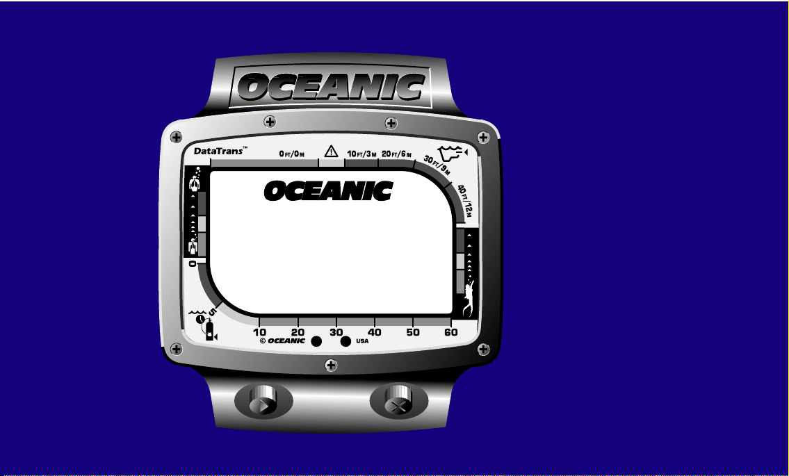
Universal Graphic Diver Interface
PSI
M
FT
20
30 40
50
60
10
5
10FT/3M20FT/6
M
30
FT
/
9
M
40
FT
/
12
M
0FT/0
M
0
Kg/Cm
2
®
One of Oceanic’s primary design objectives for dive computers has always been
to display information in a format which is as easy to read and understand as
possible, without any clutter of unnecessary information that may cause confusion
for the diver. Until now, this has been accomplished by alternately showing
primary and secondary screens of information at preset intervals. This allows the
numerical figures for each display to be as large and as easy to read as possible, but
it comes with the small inconvenience of sometimes waiting until the screen
containing the desired information appears.
The DataTrans offers the best of all worlds, and transcends many language
barriers. With the use of universal icons and four different bar graphs that make
up the Universal Graphic Diver Interface (Fig. 3), information is visually represented and understood at a glance, minimizing the need for numerical displays.
Underwater, the Control Console allows you to access an alternate display of
information containing max depth, bottom time, and temperature, with the touch
of a button - whenever you choose.
In a critical situation, however, icons, bar graphs, and numeric displays may not
be enough to convey an urgent message. The Message BoxTM is an alpha/numeric
display which flashes concise, simple messages, such as “TOO FAST,” or “AIR
ALARM,” while the audible alarm simultaneously sounds to alert you to check this
information. Most incredibly, these messages can be displayed in one of five
language preferences that you choose, using the interactive Control Console before
you enter the water.
Fig. 3 - Universal Graphic
Diver Interface
5
Page 14

d.
0
5
10
0FT/0
a.
10FT/3M20FT/6
M
PSI
2
Kg/Cm
30 40
20
c.
Fig. 4 - Bar Graph Displays
6
Color Coded Bar Graph Displays
The Graphic Diver Interface contains four separate bar graphs that are each color
coded green, yellow, and red, and can be interpreted the same as a traffic signal.
The Tissue Loading Bar Graph® (TLBG) represents (Fig. 4a) nitrogen loading,
showing your relative no-decompression or decompression status. As your depth
and bottom time increase, segments will fill the graph from left to right. As you
ascend to shallower depths, this bar graph will begin to recede, indicating that
additional no decompression time is allowed for multilevel diving. The TLBG also
assists you with managing decompression by indicating four “ceiling” depths. This
is explained in detail in the “Handling the Extremes” section.
The Variable Ascent Rate IndicatorTM (VARI) bar graph (Fig. 4b) shows you
how fast you are ascending, rather than just showing that you are ascending too
M
30
FT
FT
M
fast. You can think of it as an ascent rate speedometer.
/
9
M
40
The Air Time Remaining™ (ATR) bar graph (Fig. 4c) provides a graphic
FT
/
12
M
representation of Air Time Remaining, which represents the time that a diver can
remain at his present depth and then, following a safe ascent, surface with a
predetermined air reserve (e.g., 300 psi). This calculation and display is based on
the diver's individual air consumption rate that is continually monitored by the
50
b.
required decompression stops.
The Air Consumption Indicator™ (ACI) bar graph (Fig. 4d) is a true biofeed-
DataTrans, and it takes into account the air required for a safe ascent including any
60
back monitor that indicates your current breathing rate as compared to your
personally established breathing parameters. The comparison is based upon an
average rate established during the first 70 seconds of breaths.
Page 15

While underwater, you must check each of these four bar graphs on a frequent
basis. Oceanic strongly recommends that every effort should be made to keep each
display “in the green” at all times to minimize any possibility of decompression
sickness or an out-of-air situation. More detailed information regarding these
displays is provided in the following sections.
In addition to it's unique interactive abilities, the DataTrans is fully loaded with
all of the features you would expect from the world's leading manufacturer of dive
computers - and much, much more:
•Universal Graphic Diver Interface™ - Intuitively simple to read and understand
•Air-Integrated™ - Calculates personal air consumption in 3 displays
•Alpha-Numeric Message Box™ - Displays warning messages in preferred language
•Audible Alarm - Alerts you to check Message Box™ and Graphic Diver Interface
•Variable Ascent Rate Indicator™ - Measures ascent rate incrementally
•Dive Log Recall - Recalls 12 most recent dive profiles with time & date stamp
•Backlighted Display - Allows easy viewing at night or in low light situations
•Automatic Altitude Compensation - Fully functional up to 14,000 ft. (4,267 m.)
•Diver Replaceable Batteries
•Ambient Temperature Indication
Before moving on to the next chapter, take the time to familiarize yourself with
the universal icons, Fig. 5 on page 8, which make up the Graphic Diver Interface.
™
7
Page 16
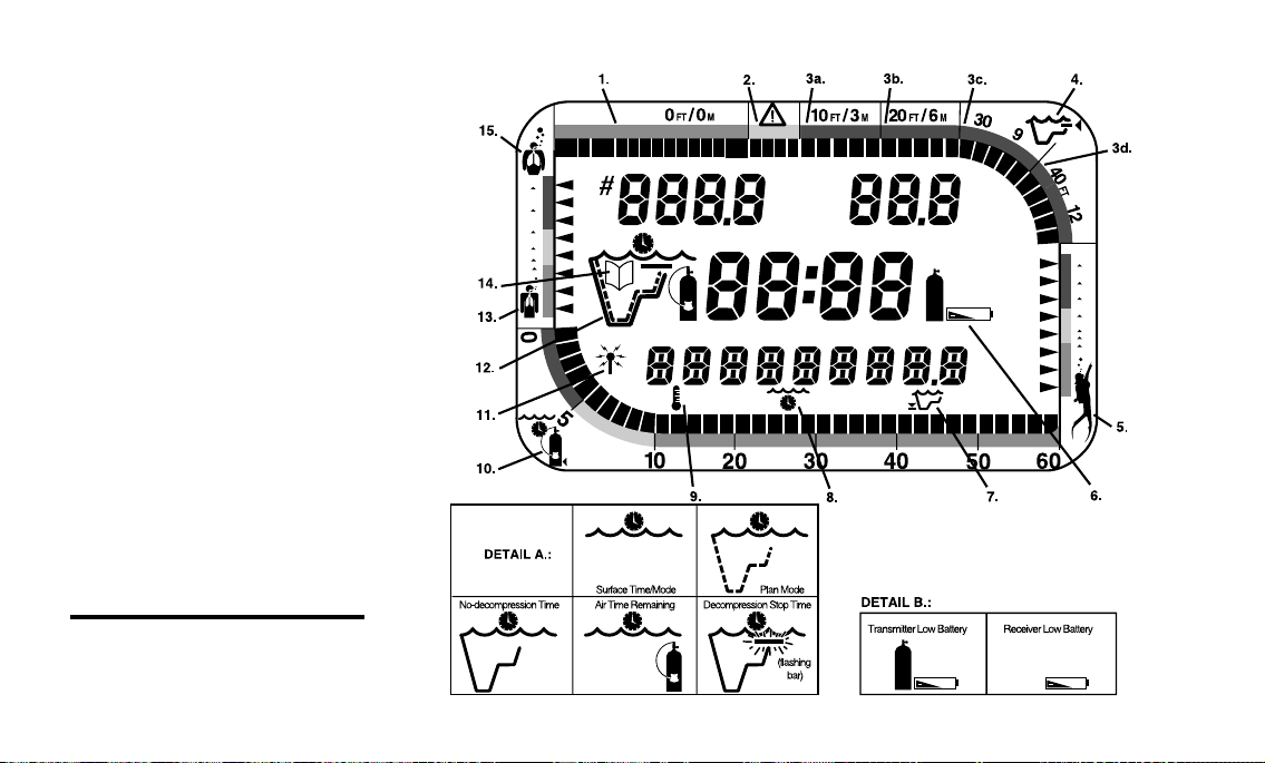
1. Tissue Loading Bar Graph
(NO DECOM ZONE)
2. Tissue Loading Bar Graph
(CAUTION ZONE)
3a. Tissue Loading Bar Graph
(10ft/ 3m DECOM CEILING)
3b. Tissue Loading Bar Graph
(20ft/ 6m DECOM CEILING)
3c. Tissue Loading Bar Graph
(30ft/ 9m DECOM CEILING)
3d. Tissue Loading Bar Graph
(40ft/ 12m DECOM CEILING)
4. Icon - Decompression Zone
5. Icon - Ascent Rate
6. Icon - Low Battery
(See Detail B)
7. Icon - Maximum Depth
8. Icon - Elapsed Bottom Time
9. Icon - Temperature
10. Icon - Air Time Remaining
11. Icon - RF Transmission Link
12. Icon - Dive Time Mode
(See Detail A)
13. Icon - Low Air Consumption
14. Icon - Log Mode
15. Icon - High Air Consumption
Fig. 5 - Graphic Interface
Legend
8
PSI
Kg/Cm
FT
/
M
2
FT
M
/
M
Page 17

GETTING
STARTED
9
Page 18

Fig. 6 - DX-3 Integrated
First Stage
10
MAKING THE DATATRANS PERSONAL
Before you dive with the DataTrans for the first time, you will need to become
acquainted with its interactive features, and select your personal display
settings using the Control Console and Mode Menu.
If you intend to use your DataTrans as a complete system that includes the
high pressure transmitter, the transmitter must first be installed into a high
pressure port of your first stage, facing to one side - unless you purchased the DX3™ Integrated First Stage, which includes the transmitter as a built-in component (Fig. 6). Oceanic strongly recommends that this installation be performed
by an Authorized Oceanic Dealer at the time of purchase. If this is not possible,
refer to the instructions for this procedure on page 80.
NOTE: The DataTrans transmitter is compatible with all Oceanic first stages, but cannot be guaranteed to fit certain models
produced by other manufacturers. Check with your Authorized
Oceanic Dealer for compatibility with your first stage.
If your DataTrans display module and transmitter were packaged and shipped
from the factory as a complete system, the two units have already been “prelinked.” If the two units have been purchased separately by you or your
Authorized Oceanic Dealer, it will be necessary to link the display module to the
transmitter's frequency code. This can be easily verified upon activation.
Page 19

A DataTrans that has been packaged and sold as a stand alone computer
M
®
PSI
FT
Kg/Cm
2
display module has been preset at the factory as a non-linked unit, but can easily
be linked with a transmitter at any time in the future.
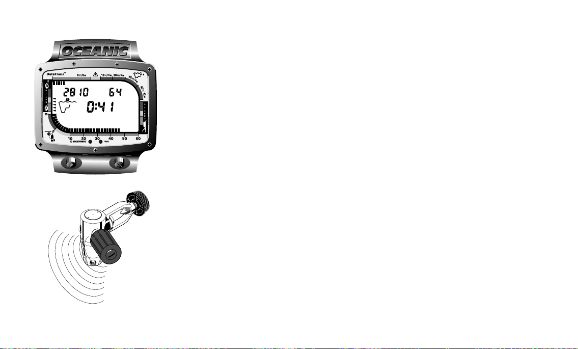
ACTIVATING THE DISPLAY
Before activating the DataTrans display module, it is very important to
connect the first stage containing the transmitter to a full cylinder and pressurize by opening the valve. Air pressure of 50 psi (3.5 kg/cm2 ) or more is necessary
to activate the transmitter. Position the display module within 3 feet (1 m) of
and parallel to the transmitter, and hold it in this location throughout the
activation process.
To activate the display of the display module, press the Select button on the
right side of the Control Console and release. The DataTrans will immediately
enter Diagnostic Mode (Fig. 7), which will display all “8’s,” followed by “dashes,”
and then a countdown from 9 to 0. The Message Box will read SELF - TEST until
the diagnostic check is completed, at which time the DataTrans will emit a single
beep to indicate a successful diagnostic check. If the display module is correctly
set to the same frequency code as the transmitter, the Link icon will disappear
and cylinder pressure will be displayed numerically. Also, the Air Time
Remaining (ATR) bar graph (Fig. 8) will fill indicating 60 minutes.
Throughout this process, the DataTrans checks its display functions, coded
frequency link to the transmitter, and battery voltage to ensure that everything
is working correctly. If any display or message varies from the information
presented here, return the DataTrans to your Oceanic Dealer for inspection. It
Fig. 7 - Diagnostic Mode
BEEEEP!!!
®
Fig. 8 - Link Verification
(ATR Bar Graph)
11
Page 20

will also check the ambient barometric pressure, and calibrate its present depth
as zero. At elevations of 3,000 ft. (915 m) or higher, it will recalibrate itself to
measure depth in feet (meters) of fresh water.
WARNING - Never activate the DataTrans underwater. This may
result in inaccurate depth and no-decompression time displays.
a.
Activation is not possible deeper than 4 ft. (1 m) underwater.
If 2 hours elapse after activation without making a dive, the DataTrans will
self-deactivate to save battery power. Check your display module before entering
the water to ensure that it doesn’t need reactivation.
PSI
FT
During diagnostic mode, the DataTrans measures the battery voltage level of
both the display module and the transmitter to determine whether there is
sufficient voltage to complete a full day of diving.
®
Fig. 9 - Low Battery Warning
12
WARNING - If either or both of the Low Battery icons remain on
display following activation (Fig. 9a), Oceanic strongly recommends that you DO NOT dive until you have obtained battery
replacement. See battery replacement procedure on page 77.
If there is not enough battery voltage in the display module to complete a day
of diving, the DataTrans will either deactivate itself or not activate at all. If there
is not sufficient voltage in the transmitter to complete a full day of diving, the link
Page 21

®
FT
PSI
icon and tank pressure of "00" PSI will flash on display (Fig. 10), indicating that
the display module is not receiving a signal.
FLASHING LINK ICON
If the display module has been successfully linked to the transmitter upon
activation, the Link icon and tank pressure will begin flashing on display
whenever the display module is moved out of the range of the transmitter while
in Surface Mode. When the display module is returned to its correct proximity
to the transmitter, the flashing will stop, and the Link icon will disappear within
5 seconds. Also the Air Time Remaining bar graph will reappear.
If a link was not established during activation, the Link icon will remain
flashing on display immediately following Diagnostic Mode, and tank pressure
of "00" PSI will be displayed, flashing. This indicates one of the following
conditions:
a. The transmitter was not pressurized prior to activation of the display
module.
b. The display module was not positioned in close proximity to the transmitter during activation or correctly positioned parallel to it.
c. The transmitter’s battery voltage has dropped below the level required to
transmit a signal.
d. The display module is not correctly linked to the same coded frequency as
the transmitter.
Fig. 10 - Unsuccessful Link
13
Page 22

In the latter case, it will be immediately necessary to follow the prescribed
linking procedure outlined on page 24 to set the display module to the coded
frequency that matches that of the transmitter, or set a specific link code that
will allow the display module to function as a stand alone unit.
SURFACE MODE
Surface Mode immediately follows Diagnostic Mode after initial activation
(Fig 11), or after the linking procedure has been performed. It also appears after
a dive when you ascend shallower than 3 ft. (1m). Surface Mode is identified by
the Surface Time icon (Fig. 11a). Information displayed in Surface Mode is Tank
Pressure, Depth, Surface Time with flashing colon, Temperature, Time of Day
PSI
FT
with colon flashing, the Air Time Remaining and Tissue Loading Bar Graphs, if
any, and the Air Consumption Indicator. The Date may be viewed as a secondary
display by pressing the Select button.
Surface Mode is also the default mode that the DataTrans will automatically
return to whenever it has been left unattended while in the Mode Menu for a
®
period of more than 5 minutes. You may find yourself automatically returned
there when you have completed a particular setting. While navigating through
the Mode Menu system, you can think of Surface Mode as “home port”.
a.
Fig. 11 - Surface Mode
14
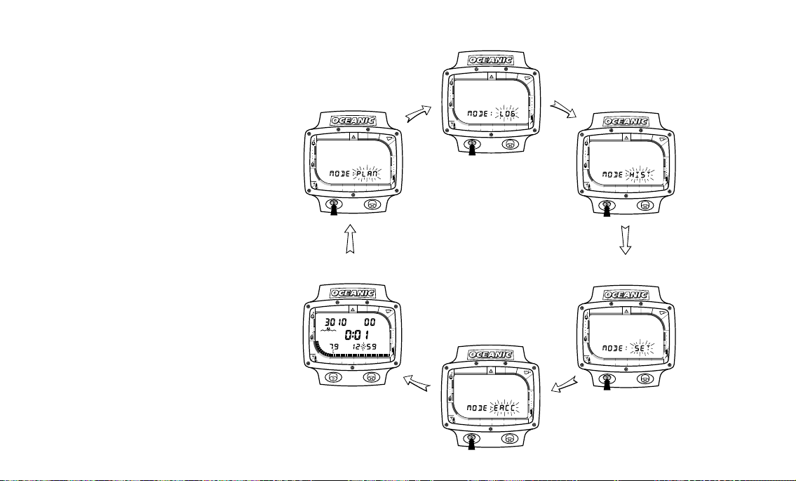
MODE MENU SYSTEM
In just a moment, you’ll begin navigating through the Mode Menu system to
set the various display options that will make the DataTrans your personal
computer. If you followed the Linking procedure, you have already developed a
Page 23

feel for how the Control Console works. The Advance button is used to move
through the Mode Menu and change each setting, and the Select button is used
to select the mode or setting that is currently on-screen. A brief glossary and
hierarchy of the menu system is as follows:
Mode - Each mode provides a different display of information, or access to a
submenu or setting. Some modes, such as Dive Mode and Surface Mode, are
entered into automatically. Others, such as the Plan Mode and Alternate Dive
Mode, are entered into via the Control Console, at the user’s option.
Menu - The main menu allows interactive access from the Surface Mode to Plan,
Log, History, Set, and External Access Modes.
Setting - These are display options, such as time, date, language, link and units
of measure (imperial or metric) that are determined by you - the user. You can
even preprogram your dive by setting the depth and air pressure at which you
will be alerted when you are going too deep or running low on air.
Take the time to become familiar with the Menu System by studying the
flowchart diagrams shown on the following pages.
NOTE: If the DataTrans is left unattended for five minutes while
in the Mode Menu, it will automatically return to Surface Mode.
15
Page 24
Mode Menu
Plan Mode
(Pre Dive Planning Sequence )
0FT/0
M
10FT/3M20FT/6
M
30
FT
/
9
M
40
FT
/
12
M
0
5
10
20
30 40
60
50
Dive Log
(Dive Log Recall)
10FT/3M20FT/6
0FT/0
M
0
5
10
30 40
20
M
30
FT
/
9
M
40
FT
/
12
M
60
50
History Mode
(Complete Unit History)
0FT/0
M
10FT/3M20FT/6
M
30
FT
/
9
M
0
5
10
20
30 40
60
50
40
FT
/
12
M
16
Start in
Surface
Mode
Surface Mode
(Default)
0FT/0
0
5
10
Set Mode
(Access Sub-Menus)
10FT/3M20FT/6
M
M
30
FT
/
9
M
40
FT
FT
PSI
20
30 40
/
12
External Access Mode
M
(Optional External Interface Feature)
60
50
0
5
10FT/3M20FT/6
M
0FT/0
M
30
FT
/
9
M
40
FT
/
12
M
30 40
60
50
10
20
0FT/0
M
10FT/3M20FT/6
M
30
FT
/
9
M
40
FT
/
12
M
0
5
10
20
30 40
60
50
Page 25

Settings
Start
in Set
Mode
Set Mode
(Access Submenus)
0
5
10
20
30 40
60
50
Time Setting
(Set Time of Day)
0
5
10
20
30 40
60
50
Language Setting
(Set Language)
0
5
10
20
30 40
60
50
Date Setting
(Set Today's Date)
0
5
10
20
30 40
60
50
Link Setting
(Set Frequency Link)
0
5
10
20
30 40
60
50
Unit Setting
(Set Units of Measure)
0
5
10
20
30 40
60
50
Alarm Setting
(Set Air & Depth)
0
5
10
20
30 40
60
50
17
Page 26

®
ADVANCE SELECT
®
Fig. 12 - Time of Day Setting
18
SETTING THE MODES
Now you can begin setting your personal display preferences, using the
interactive Control Console and the Setting Submenu. You will initially set Time
and Date, followed by Units of measure and Language.
SET TIME
Time of day is displayed during the Surface and Alternate Dive modes, and
each dive recorded in Log Mode is “stamped” with the time of day that the dive
started. Your DataTrans has been factory set for 12:00 AM. To change to the
current Time, follow this procedure, beginning in Surface Mode:
1. Press the Advance button to enter the MODE Menu. MODE:PLAN will
appear, with PLAN flashing, indicating that Plan Mode is the first available
option.
2. Press the Advance button 3 more times to advance to the Set Mode
(MODE:SET will appear, with SET flashing). If you accidentally pass the Set
Mode, you will need to press the Advance button repeatedly until MODE:SET
appears. Press the Select button to select the Set Mode.
3. SET:TIME will appear, with TIME flashing.
4. Press the Select button to select the Time setting. Time of day will appear,
with the first digit flashing (Fig. 12).
5. To set the time, press the Advance button to change each digit until it
matches that of the current time, and press the Select button to set each digit
and move on to the next. Finally, press the Advance button to display either
Page 27

®
AM or PM, and press the Select button to enter the setting.
®
6. After the time has been set, SET:DATE will appear with DATE flashing.
Press the Advance button 5 times to return to the Surface Mode, or to set the
date continue with step 4 of the following SET DATE procedure.
SET DATE
Each dive shown in Log Mode is “stamped” with the date that the dive was made.
The current date may be viewed in Surface Mode by pressing the Select button.
Your DataTrans has been factory set for JAN 1 96. To change to the current Date,
follow this procedure, beginning in Surface Mode:
1. Press the Advance button to enter the Mode Menu. MODE:PLAN will
appear, with PLAN flashing, indicating that Plan Mode is the first available
option.
2. Press the Advance button 3 more times to advance to the Set Mode
(MODE:SET will appear, with SET flashing). If you accidentally pass the Set
Mode, you will need to press the Advance button repeatedly until MODE:SET
appears. Press the Select button to select the Set Mode.
3. After selecting Set Mode, press the Advance button once to advance to the
Date setting (SET:DATE will appear, with DATE flashing).
4. Press the Select button to select the Date setting. The month will appear,
flashing (Fig. 13).
5. To set the Date, press the Advance button to change month, day, and year
until they each match that of the current date. Press the Select button to set
ADVANCE SELECT
Fig. 13- Date Setting
19
Page 28

®
ADVANCE SELECT
PSI
®
FT
Fig. 14 - Units of Measure
Preference Setting
20
each of these and advance to the next.
6. After the year has been set, SET:UNIT will appear, with UNIT flashing.
Press the Advance button 4 times to return to the Surface Mode, or to set the
units continue with step 4 of the following SET UNIT procedure.
SET UNITS OF MEASURE
You can choose between Imperial (PSI and Feet) and Metric (Kg/Cm2 and
Meters) units of measure to display air pressure and depth information. Your
DataTrans has been factory set for FT and PSI. To change display values to
metric units of measure, follow this procedure, beginning in Surface Mode:
1. Press the Advance button to enter the Mode Menu. MODE:PLAN will
appear, with PLAN flashing, indicating that Plan Mode is the first available
option.
2. Press the Advance button 3 more times to advance to the Set Mode
(MODE:SET will appear, with SET flashing). If you accidentally pass the Set
Mode, you will need to press the Advance button repeatedly until MODE:SET
appears. Press the Select button to select the Set Mode.
3. After selecting Set Mode, press the Advance button twice to advance to the
Unit setting (SET:UNIT will appear, with UNIT flashing).
4. Press the Select button to select the Unit setting. PSI and FT will appear
in the upper portion of the screen, flashing (Fig. 14).
5. You may press the Select button to select Imperial units of measure, or you
may press the Advance button once to display Kg/Cm2 and M, and press the
Page 29

SELECT button to select Metric units of measure.
6. After the Units have been set, SET:ALRM will appear with ALRM flashing.
Press the Advance button 3 times to return to the Surface Mode, or to set the
alarms continue with step 4 of the Set Air and Depth Alarm procedure
beginning on page 23.
AIR & DEPTH ALARM SET POINTS
™
After planning each dive according to the no-decompression bottom
times shown to be available in the PDPS, Oceanic strongly recommends that you utilize one of the greatest safety features the DataTrans
offers - the Air & Depth Alarm settings.
While the DataTrans uses the Audible Alarm, Message Box, and
Graphic Diver Interface to automatically alert you whenever you enter
a potentially dangerous situation, such as Decompression Dive Mode,
ascending too fast, running low on air, etc., the Alarm settings allow
you to preset more conservative limits to better avoid these situations.
Depth Alarm Set Point
™
The Depth Alarm will alert you whenever you reach or exceed the maximum
depth Set Point that you have chosen. Of course, if you set the Depth Alarm for
a depth that is deeper than the no-decompression or decompression limits for
that dive, you will first be alerted by other built-in alarms that you have exceeded
those limits before the Depth Alarm is activated. When the Depth Alarm is
activated by reaching or exceeding your preset maximum depth, the audible
PSI
FT
BEEEEP!!!
®
Fig. 15 - Depth Alarm
(90 FT Set Point)
21
Page 30

Fig. 16 - Air Alarm
(500 PSI Set Point)
22
alarm will sound once per second, while the Message Box flashes the words “TOO
DEEP” (Fig. 15, page 21) until you ascend above the depth Set Point. The Depth
Alarm may be set for depths ranging from 30-250 feet (9-76 m), in 10 ft (3 & 3.5
m) increments. The setting that you choose for the Depth Alarm does not change
the displayed limits of no-decompression dive time remaining.
Air Alarm Set Point
™
The Air Alarm is an acoustic alert that indicates you are approaching a critical
Air Time Remaining. The Air Alarm Set Point refers to the surfacing tank
pressure reserve of your choice, which may be set for pressures ranging from 300
to 1000 psi.
You will recall that Air Time Remaining is the time that you can remain at your
PSI
FT
present depth and, following a safe ascent, still surface with a prescribed air
reserve (identified here as the Air Alarm Set Point).
When your Air Time Remaining reaches 5 minutes, the Air Alarm will emit a
double beep as a preliminary warning. If you allow your Air Time Remaining to
BEEEEP!!!
®
decrease to zero, the tank pressure display will flash and the Message Box flashes
the words "AIR ALARM" (Fig. 16) until you ascend to a depth of 5 feet or less.
While an immediate ascent is called for if the Air Time Remaining decreases
to zero, there is no reason to panic. The DataTrans has allowed for the air you
will consume during a safe ascent, including decompression stops if they are
required, and still provide the tank pressure reserve you have chosen, e.g., 300
psi.
Page 31

Turning Off the Audible Alarm
®
FT
The audible portion of the alarm may not be desired by some divers in certain
situations. Underwater photographers, for instance, may find that the alarm
frightens off marine life at a close distance, and will therefore want to turn it off
temporarily before they begin a dive involving that activity. In other situations,
such as a multiday trip, when spare batteries are in scarce supply, the audible
alarm may be turned off to conserve battery power. For these reasons, the
audible portion of the alarm feature may be turned off at your discretion. The
Graphic Diver Interface and Message Box will continue to display information
according to the values that have been entered in the Alarm settings.
WARNING: Turning off the audible alarm disables an important
tool that can help you avoid decompression diving or low air
emergencies. Although possible, Oceanic does not recommend
the disablement of the audible alarm for any purpose.
Set Air and Depth Alarms
Your DataTrans alarms have been factory set for 250 FT and 300 PSI. To set
with your desired Depth and Air Alarm settings, or turn the audible alarm off,
follow this procedure, beginning in Surface Mode:
1. Press the Advance button to enter the Mode Menu. MODE:PLAN will
appear, with PLAN flashing, indicating that Plan Mode is the first available
option.
2. Press the Advance button 3 more times to advance to the Set Mode
Fig. 17 - Depth Alarm Setting
23
Page 32

(MODE:SET will appear, with SET flashing). If you accidentally pass the Set
Mode, you will need to press the Advance button repeatedly until MODE:SET
appears. Press the Select button to select the Set Mode.
3. After selecting Set Mode, press the Advance button 3 times to advance to
the Alarm setting (SET:ALRM will appear, with ALRM flashing).
4. Press the Select button to select the Alarm setting. The current Depth
Alarm Set Point value will appear, flashing (Fig. 17, page 23).
5. Press the Advance button repeatedly to change the Depth Alarm Set Point
between 30 FT (9M) and 250 FT (76M) in 10 foot (3m) increments to the depth
you choose, and press the Select button to enter that setting. The current Air
Alarm Set Point value will appear, flashing (Fig. 18).
PSI
6. Press the Advance button repeatedly to change the Air Alarm Set Point
between 300 PSI (21 Kg/Cm2) and 1000 PSI (70 Kg/Cm2) in 100 PSI (7 Kg/
Cm2) increments to the pressure you choose, and press the Select button to
enter that setting. ALARM:ON will appear, with the word “ON” flashing
(unless the audible alarm has been previously deactivated).
®
7. Press the Advance button to turn the audible portion of the alarm 'on' or 'off'.
8. After the Alarms have been set, SET:LINK will appear with LINK flashing.
Press the Advance button 2 times to return to the Surface Mode, or to se t the
Link code continue with step 4 of the following LINKING procedure.
Fig. 18 - Air Alarm Setting
24
LINKING PROCEDURE
Your DataTrans display module has been factory set with the transmitter's
Page 33

®
serial number, or at SN999999 if no tranmitter was purchased. If the DataTrans
Linked automatically immediately following activation, there is no need to
perform the Linking procedure. However, if the Link icon and pressure value
of 00 remained flashing on-screen, the Linking procedure must be performed
before the display module can receive air supply data from the transmitter.
The Linking procedure may also need to be performed in the event that your
DataTrans display module or transmitter has received factory service, and is
returned to you with a different frequency code. You may also choose to “unlink”
your display module from the transmitter to use it as a stand alone computer,
without its air-integrated features, or to link it to a transmitter which has been
purchased separately at a time in the future.
While holding the display module within 3 feet (1 m) of the transmitter, which
must be installed into a first stage regulator and pressurized with air, perform
the following steps to link the display module to the transmitter’s frequency
code:
1. Press the Advance button to enter the Mode Menu. MODE:PLAN will
appear, with PLAN flashing, indicating that Plan Mode is the first available
option.
2. Press the Advance button 3 more times to advance to the Set Mode
(MODE:SET will appear, with SET flashing). If you accidentally pass the Set
Mode, you will need to press the Advance button repeatedly until MODE:SET
appears. Press the Select button to select the Set Mode.
3. After selecting the Set Mode, press the Advance button 4 times to advance
ADVANCE SELECT
®
Fig. 19 - Link Setting
25
Page 34

a.
Fig. 20 - Transmitter
Frequency Code (Serial No.)
®
Fig. 21 - Optional Non-Link
Frequency Code
26
to the LINK setting. (SET:LINK will appear, with LINK flashing).
4. Press the Select button to select the Link Mode (Fig. 19, page 25), and
compare the 6 digit frequency code number which is shown on display to the
first 6 digits of the serial number embossed on the transmitter (Fig 20).
4a. If these numbers are the same, check to ensure that the cylinder valve
is open, and that the first stage regulator which contains the transmitter
is pressurized. While holding the display module within 3 feet (1 m) of and
parallel to the transmitter, press the Select button 6 times to select the
same serial code which is on display. DO NOT press the Advance button,
which will change the code to an incorrect number.
5. If the frequency code of the display module does not correspond with the
transmitter’s serial number, you must set the code correctly as follows:
5a. Press the Advance button to change each number of the code as
required. When each number matches the corresponding number of the
transmitter, press the Select button to set that number and move on to
the next. Repeat this procedure until all 6 numbers are set.
6. If you would like to set the display module to allow it to function as a stand
alone, non air-integrated computer, use the Advance and Select buttons as
described above to set the code as 999999 (Fig. 21).
7. After the Link code has been set, SET:LANG will appear with LANG
flashing. Press the Advance button once to return to the Surface Mode, or to
set your preferred Language continue with step 4 of the following SET
LANGUAGE procedure.
Page 35

®
®
SET LANGUAGE
The DataTrans Message Box displays warning messages in one of five lan-
guages that you choose - either English, Italian, German, Spanish, or French.
The Mode Menu system is also displayed in whichever language is
selected, so it is very important that you do not accidentally change
this setting to a language that you do not understand. Your DataTrans
has been factory set for English. If you wish to change the DataTrans’ language,
you may do so by following this procedure, beginning in Surface Mode:
1. Press the Advance button to enter the Mode Menu. MODE:PLAN will
appear, with PLAN flashing, indicating that Plan Mode is the first available
option.
2. Press the Advance button 3 more times to advance to the Set Mode
(MODE:SET will appear, with SET flashing). If you accidentally pass the Set
Mode, you will need to press the Advance button repeatedly until MODE:SET
appears. Press the Select button to select the Set Mode.
3. After selecting Set Mode, press the Advance button 5 times to advance to
the Language setting (SET:LANG will appear, with LANG flashing).
4. Press the Select button to select the Language setting. The default setting
ENGLISH will appear in the lower portion of the screen, flashing (Fig. 22).
5. Press the Advance button to scroll through the Language setting options
until you arrive at the one you prefer.
6. Be careful to ensure that the language selection flashing is the one which
you prefer before you press the Select button.
ADVANCE SELECT
Fig. 22 - Language Preference
Setting
27
Page 36

®
Fig. 23 - Set : Link as seen in
German (Deutsch)
28
7. Press the Select button to set the Language chosen and return to the
Surface Mode.
Language Correction Procedure
If you accidentally selected a language which you do not prefer or understand,
you may find it very confusing to navigate further in the Mode Menu or
understand the Message Box warnings (Fig. 23). To correct the DataTrans to
display your preferred language, it is recommended that you wait 5 minutes to
allow default to the Surface Mode, and carefully perform the steps outlined in the
following procedure:
1. Press the Advance button four times to arrive at the Set Mode.
2. Press the Select button once to enter Set Mode.
3. Press the Advance button five times to arrive at the Language submenu.
4. Press the Select button once to select the Language submenu.
5. Press the Advance button as needed until your preferred language appears.
6. Press the Select button to enter your language preference. You will
automatically return to Surface Mode.
NOTE: See page 93 in the Reference section for a cross reference of terminology using the five available languages.
Page 37

DIVING
WITH THE
DATATRANS
29
Page 38

®
PSI
FT
®
PSI
FT
®
PSI
FT
®
PSI
FT
®
PSI
FT
Poor
reception
area.
Poor reception distance.
(Greater than 3 feet)
Fig. 24 - Radio Frequency (R/F)
Reception
30
Poor
reception
area.
Best
reception
zone.
Page 39

®
PSI
FT
POSITIONING OF THE DISPLAY MODULE
The DataTrans transmitter emits a radio frequency (R/F) signal that radiates
a short distance outward in a semicircular pattern that is parallel to the length
dimension of the transmitter (Fig. 24, page 30). The coiled antenna inside the
display module is designed to receive this signal when the display module is held
in a zone parallel to or at a 45 degree angle to the transmitter. The display
module cannot effectively receive the transmitter's signal when the module is
held out to the sides of the transmitter, or held at distances greater than 6 feet
(2 m) in front of the transmitter. Best signal strength and reception is achieved
when the display module is within 3 feet (1 m) of the transmitter.
When installed into a high pressure port of your first stage regulator, the
transmitter must be positioned so that it faces horizontally outward from the
cylinder valve.
Link Interruption Underwater
It is possible that you may inadvertently move the display module out of the
signal pattern resulting in temporary link interruption.
A link interruption of from 15 to 20 seconds will be indicated by a flashing
Link icon and flashing tank pressure (Fig. 25). Also, an audible alarm will sound
once per second until the link is restored. The link will be restored within 4
seconds after the display module is moved back into its correct position.
A link interruption may also occur while the display module is in an area 3
to 4 feet (1 m) from a running dive propulsion vehicle. The link will be restored
Fig. 25 - Underwater Link
Interruption
31
Page 40

32
4 seconds after the vehicle motor is shut off or when the display module is moved out
of this area.
When using a photo strobe, temporary link interruption may occur shortly after
the strobe flashes. The link will be restored in 4 seconds.
WARNING: During the period of link interrupt the display module
will temporarily loose transmitted pressure related functions and
displays. These will be regained 4 seconds after the link is restored.
Page 41

®
FT
OPERATIONAL MODES
The DataTrans operates in 13 different operational modes, including the
Diagnostic, Surface, and Set Modes which have already been explained in
detail in the previous chapter, “Getting Started.” This chapter will explain the
modes the DataTrans operates in before, during, and after a dive.
PRE DIVE PLANNING SEQUENCE (PLAN MODE)
Prior to every dive, Oceanic strongly recommends that you access
the Plan Mode to review the Pre Dive Planning Sequence (PDPS) that
will help you plan your dive as required to avoid decompression. This
is especially important for repetitive dives, when the PDPS will advise you of the
no-decompression bottom times that are available to you on your next dive,
based on any residual nitrogen following your last dive and surface interval.
To access the Plan Mode, press the Advance button once while in Surface
Mode. MODE:PLAN will appear, with PLAN flashing. Press the Select button
to enter the Plan Mode (Fig. 26).
Upon entering the Plan Mode before a “clean” dive (no dives in 24 hours), the
PDPS will immediately appear and scroll once through depths from 30 to 160 feet
(9 to 48 m) in 10 foot (3 m) increments, showing predicted no-decompression dive
times based upon your previous dive profiles. The information displayed is
Previous Dive #, Depth, No-Decompression Dive Time available at that depth,
and no-decompression dive icon.
Fig. 26 – Plan Mode
33
Page 42

WARNING: The PDPS predicts only no-decompression times for
subsequent dives. Depending on cylinder size and air consumption, you may have less time available than shown in the PDPS
because of air or other limitations.
PDPS no-decompression times are displayed for depths where there is at least
1 minute available. This takes into account a descent rate of 75 ft./min (23 m/
min). Before a “clean” dive (no dives in 24 hours), the PDPS no-decompression
limits are those found on page 84 in the Reference section.
PSI
FT
After scrolling once through depth and bottom times available, the DataTrans
will return to Surface Mode. Plan Mode can be accessed and the PDPS can be
repeated as often as you choose. If you wish to interrupt the PDPS to return to
Surface Mode, you may do so at any time by pressing either control button.
®
Fig. 27 – No Decompression
Dive Mode
34
NO DECOMPRESSION DIVE MODE
The DataTrans will automatically enter No-Decompression Dive Mode when
you descend deeper than 5 feet (1.5 m). This mode can be recognized by the Dive
Time Remaining icon that is displayed immediately to the left of the numeric
display of dive time remaining (Fig. 27). The numeric value displayed will always
represent your true dive time remaining, either Air Dive Time remaining or Nodecompression Dive Time remaining (whichever is less).
At shallower depths and at the beginning of a first dive, the Dive Time
Remaining Icon will represent Air Time, to indicate that available bottom time
at your present depth is limited by your air supply, and is less than the time that
would be allowed by the calculated no-decompression limits.
Page 43

As your depth and bottom time increase, however, No-Decompression Time
eventually becomes the more limiting factor, and the Dive Time Remaining Icon
will indicate that the numeric display is showing this value.
No-Decompression Dive Mode numerically displays Cylinder Pressure, Current Depth, and No Decompression or Air Dive Time Remaining (whichever is
less). The Graphic Diver Interface displays the TLBG, VARI, ATR, and ACI bar
graphs.
As your depth and bottom time increase, the TLBG will fill up with segments
from left to right (green to red) to represent the absorption of nitrogen. Upon
ascent to shallower depths, the TLBG will begin to recede, indicating the
additional no decompression time available through multilevel diving.
ALTERNATE DIVE MODE
To avoid cluttering of the screen, values of Temperature, Maximum Depth,
Bottom Time, and Time of Day are displayed in an Alternate Dive Mode (Fig. 28).
To view the Alternate Dive Mode, simply press and hold the Select button at
any time throughout your dive. Displays of Temperature (28a), Bottom Time
(28b), and Maximum Depth (28c) appear in addition to information displayed in
the normal Dive Mode. When you release the Select button, Time of Day will
appear briefly before the screen returns to the Dive Mode.
FT
PSI
®
a.
b.
c.
Fig. 28 - Alternate Dive Mode
FT
PSI
®
BACKLIGHTING FEATURE
During Dive Mode press the Advance, left, button (Fig. 29) to illuminate the
Oceanglo™ backlight for depression time plus 10 sec, or 15 sec maximum.
Fig. 29 - Oceanglo™ Backlight
35
Page 44

DECOMPRESSION DIVE MODE
The DataTrans will help you to avoid, or easily manage, decompression.
Before explaining further, read the following warning.
PSI
®
c.
Fig. 30 - Decompression Dive
Mode
FT
36
a.
WARNING: Oceanic recommends the application of responsible
diving practices and does not recommend decompression diving
or diving deeper than 130 feet (39 m), as these practices will
greatly increase your risk of decompression sickness.
The Decompression Dive Mode activates when the TLBG enters the red
decompression zone (Fig. 30a). When this occurs, the numeric No-Decompression dive time remaining display becomes zero and switches to Decompression
dive time required (Fig. 30b). The Mode Icon changes from No-Decompression
to Decompression (Fig. 30c). At the same time, the audible alarm will emit a
double beep to alert you of your entry into decompression, while the Message Box
alternately flashes “CEILING” and the time that you must spend decompressing
below the ceiling depth shown in the TLBG (Fig. 31, next page).
Decompression Dive Mode numerically displays Depth, Decompression Time,
and Tank Pressure. In addition to the ATR, ACI, and VARI bar graphs, the
b.
Graphic Diver Interface displays the TLBG, that now acts as a Decompression
“ceiling” indicator. Decompression time displays the total number of minutes
required at all ceilings combined. The TLBG displays the ceiling depth that you
must stay below.
Page 45

When the audible alarm alerts you of entry into decompression, you must
®
®
immediately change the focus of your dive to getting safely back to the surface.
Upon hearing the alarm and seeing the TLBG enter the 10 FT/ 3M STOP zone,
you should immediately begin a safe ascent to a depth slightly deeper than or
equal to 10 feet (3m). The amount of decompression credit time you receive is
dependent on depth, with slightly less credit given the deeper you are.
Still, you must never ascend shallower than your decompression
ceiling. Doing so will place the DataTrans into a Conditional Violation Mode,
and will greatly increase your risk of decompression sickness. Often
while coping with surge and swell, it is difficult to stay at a chosen depth. To
ensure that you do not enter a violation mode you should stay close to, but no
shallower than, the decompression ceiling depth. If the DataTrans requires a 10,
20, 30 or 40 foot (3, 6, 9 or 12 m) decompression ceiling, you should stay slightly
deeper than the depth indicated until the TLBG recedes into the next shallower
zone. When that occurs, you can ascend to, but not shallower than, the indicated
ceiling.
Once you have performed the required decompression, the DataTrans will
switch to No Decompression Dive Mode, allowing additional time underwater.
Though more time may be available, you must spend a portion of this time
continuing to decompress at a safety stop deeper than or equal to 10 feet (3m).
This will let the TLBG recede further into the yellow Caution Zone or green No
Decompression zone. During a dive in which you inadvertently enter decompression, you must focus on reducing your tissue loading as much as possible - by
spending as much time as you can at your final safety stop.
Fig. 31 - Alternating Decom-
pression Message
37
Page 46

Fig. 32 - Gauge Mode
38
VIOLATION MODES
The DataTrans enters one of three Violation Modes when you exceed its
ability to predict an ascent procedure. These modes are explained fully in the
“Handling the Extremes” section beginning on page 55.
GAUGE MODE
If the DataTrans enters a Permanent Violation Mode, it will operate only in
Gauge Mode on subsequent dives. The DataTrans removes the displays that can
no longer provide correct information because of the violation. Only depth and
cylinder pressure will be displayed, with the Message Box flashing “VIOLATION” (Fig. 32), and the audible alarm emitting one beep per second. The
PSI
FT
Alternate Dive Mode can be accessed to display temperature, bottom time, and
max depth.
ASCENDING TO THE SURFACE
As you begin ascending to shallower depths during the later part of your dive,
®
the segments that have filled up the TLBG will begin to recede, offering a graphic
representation of your multilevel diving capability. If you entered Decompression Mode, you must not complete your ascent until the TLBG is at least inside
the yellow Caution Zone. If you have not entered Decompression Mode,
a safety stop made between 15-20 feet (4.5-6m) is strongly recommended as a standard procedure before completing your ascent.
Whenever your air supply allows, you should always make every effort to
Page 47

complete your ascent with the TLBG inside of the green zone. While you
®
PSI
FT
cannot provide a guarantee against the occurrence of decompression
sickness, you may choose your own personal zone of caution based
upon your individual age, physique, excessive weight, training, experience, etc. to reduce the statistical risk.
The Variable Ascent Rate Indicator™ (VARI) will show how fast you are
ascending, in relation to the prescribed ascent rate for the depth zone you are in.
When it enters the red zone, indicating that you have exceeded the maximum
prescribed ascent rate, the DataTrans will also alert you with an audible alarm,
flashing VARI, and the Message Box will flash the words “TOO FAST.”
When you ascend to 3 feet (1m) or shallower, the DataTrans will automatically enter Surface Mode and begin counting your surface interval. For the first
10 minutes after surfacing, the Surface Mode Icon will flash (Fig. 33) to indicate
that if you descend, it will be considered a continuation of that dive. This time
at the surface will not be added as bottom time. During this time, the Mode Menu
cannot be accessed, with the exception of Log Mode. After 10 minutes has
elapsed, the Surface Mode Icon will become solid to indicate that you have full
access to the Mode Menu, and another descent will be considered a separate dive.
Fig. 33 - Surface Interval - First
10 minutes
39
Page 48

DIVE LOG MODE
Log Mode can be accessed using the Mode Menu while on the surface. This
mode displays 3 separate screens of information for each dive recorded, for up to
®
12 of your most recent dives. Log Mode will store this information indefinitely,
until a subsequent (13th) dive displaces the earliest dive recorded, on a first in,
first out basis. To eliminate confusion, each dive is separately “stamped” with
the date on which it was made, and the time of day when it was started.
a.
®
Fig. 34 - Log Mode Date Stamp
40
To access Log Mode, follow this procedure, beginning in Surface Mode:
1. Press the Advance button to enter the Mode Menu. MODE:PLAN will
appear, with PLAN flashing, indicating that Plan Mode is the first available
option.
2. Press the Advance button once to advance to the Log Mode (MODE:LOG
will appear (Fig. 34), with LOG flashing. If you accidentally pass the Log
Mode, you will need to press the Advance button repeatedly until MODE:LOG
appears. Press the Select button to select the Log Mode.
3. The first screen to appear will display the most recent dive recorded,
identified by the Log Mode Icon, the dive number and the date of the dive.
4. If you wish to bypass the dive currently being displayed to view an earlier
dive, you may do so now by pressing the Select button until the desired dive
is displayed, identified by the dive number and date of the dive.
Page 49

5. To display the time of day when the dive started, press the Advance button.
®
6. Press the Advance button once more to view the actual dive information
(Fig. 35). Displayed will be: Log Mode Icon, Dive number (35a), Surface Time
- between that dive and the one previous to it (35b), water Temperature (35c)
at the end of the dive, Bottom Time (35d), and Maximum Depth (35e). If the
dive shown in the log display was the only one of the day, Surface Time will
represent the time between initial activation and the beginning of the first
dive. Also shown will be the TLBG reading recorded at the end of the dive,
and the maximum value reached on the VARI and the ACI bar graphs.
7. Press either button to advance to the date stamp screen of the next dive.
To exit Log Mode, it will be necessary to advance through all recorded dives,
after which you will automatically return to Surface Mode.
a.
®
b.
c.
d.
e.
Fig. 35 – Dive Log Information
41
Page 50

TIME TO FLY MODE
The longer you wait to fly after diving, as you should be aware from
your own training, the more you will reduce your exposure to decompression sickness. The Time To Fly counter begins counting down ten
minutes after the last dive has ended to assist you with deciding when enough
surface time has elapsed to fly. It appears prior to the PDPS when you access
Plan Mode, and shows the word “FLY” with a countdown that starts at 23 hours
and 50 minutes (Fig. 36).
Twelve hours after the last dive, the Surface Mode will disappear from the
screen, and the Time to Fly Mode will display continuously, counting down the
remaining twelve hours to zero. After a surface interval of twelve hours, you may
choose to fly, provided that your dive profile(s) did not enter decompression. If
your diving involved decompression or a repetitive, multiday profile, it is
strongly recommended that you wait a full twenty four hours after your last dive
to add a greater degree of protection. See page 53 for more information about
flying after diving and DAN's guidelines.
®
Fig. 36 - Time to Fly Count-
down
42
WARNING: During the final twelve hours, the DataTrans is in a
countdown mode only and must be reactivated before it can be
used for another dive.
HISTORY MODE
The History Mode offers a complete history of your DataTrans computer
since it was originally purchased or last received factory service, including total
Page 51

number of dives, total decompression dives, total bottom time in hours, deepest
maximum depth, and total violations.
To access the information provided in History Mode, follow this procedure,
beginning in Surface Mode:
1. Press the Advance button to enter the Mode Menu. MODE:PLAN will
appear, with PLAN flashing, indicating that Plan Mode is the first available
option.
2. Press the Advance button 2 more times to advance to the History Mode
(MODE:HIST will appear, with HIST flashing). If you accidentally pass the
History Mode, you will need to press the Advance button repeatedly until
MODE:HIST appears. Press the Select button to select the History Mode.
3. Screen #1 will show the No Decompression Icon, total number of dives (Fig.
37a), total bottom time (Fig. 37b), and max depth (Fig. 37c).
4. Press the Advance button once to view screen #2 that shows the Decompression Icon and the total number of Decompression dives. Total bottom
time and maximum depth will remain on display (Fig. 38).
5. Press the Advance button again to view a third and final screen (#3) which
displays the Dive Mode Icon and the total number of dives during which the
DataTrans entered a Violation Mode (Fig. 39).
6. To return to Surface Mode, press either button.
NOTE: Previous unit history will be erased whenever your
DataTrans receives factory service.
®
Screen #2
(Deco Dives)
a.
®
b.
Fig. 37 – History Mode
Screen #1 (Totals)
®
Screen #3
(Violations)
c.
43
Page 52

®
Fig. 38 - External Access Mode
a.
FT
/
PSI
Kg/Cm
2
FT
M
c.
Fig. 39 - Primary Numeric
Displays
44
EXTERNAL ACCESS MODE (EACC)
“EACC,” referred to as the External Access Mode, is the last mode selection
in the main Mode Menu before Surface Mode (Fig. 38). This special mode enables
you to download recorded log and history information from your DataTrans
computer to an IBM compatible PC using an OceanLink™ download interface kit
that may be purchased separately from your Authorized Oceanic Dealer. Complete instructions for this procedure are included with the kit.
INFORMATIONAL DISPLAYS
b.
It is imperative that you understand the formats, ranges, and values of the
information represented by the DataTrans' numeric and graphic displays to
M
/
M
avoid any possible misunderstanding that could result in an error. This section
describes each display in detail.
Cylinder Pressure Display
The cylinder Pressure Display, located in the upper left portion of the LCD
(Fig. 39a), indicates how much air is in your cylinder, up to 5,000 PSI (352 Kg/
Cm2) to the nearest 10 PSI (.5 Kg/Cm2).
Depth Display
The Depth Display, located in the upper right portion of the LCD (Fig. 39b),
indicates depth from 0 to 250 feet (76 m) in 1 foot (.5 m) increments. In the event
that you descend deeper than 250 feet (76 m), this display will show three dashes
Page 53

to indicate that you have gone out of range until you ascend to 250 feet (76 m)
or shallower.
Time Display
The Time Display, located in the middle of the LCD (Fig. 39c, page 44),
indicates Air Time Remaining, No Decompression Dive Time Remaining, Bottom Time, Total Decompression Ceiling Stop Time or Surface Time, depending
on the mode that the DataTrans is in. Time displays are in hour:minute format,
i.e.; 1:06=one hour and six minutes (not 106 minutes). The colon that separates
the hour and minute display blinks once per second when indicating real time,
such as Surface Time and Bottom Time. Dive Time Remaining is a calculated
projection of time and uses a solid (non-blinking) colon to indicate that it is
counting down, rather than counting up.
UNIVERSAL GRAPHIC DIVER INTERFACE
®
Four different bar graphs are located around the perimeter of the DataTrans
LCD (Fig. 40). They are color coded green, yellow, and red to denote normal,
caution and danger zones, respectively. The Graphic Diver Interface provides
you with quick visual reference underwater to your no decompression status,
ascent rate, air time remaining, and relative air consumption. By keeping these
bar graphs “in the green” at all times, you'll greatly reduce your exposure to
decompression sickness or an out of air situation. A detailed description of each
graph follows.
10FT/3M20FT/6
0FT/0
M
TLBG
M
30
FT
/
9
M
40
ACI
0
5
ATR
10
30 40
20
ARI
50
60
Fig. 40 - Graphic Diver Interface
(Bar Graphs)
45
FT
/
12
M
Page 54

Fig. 41 - Tissue Loading Bar
ft/min
121+
91-120
61-90
51-60
41-50
31-40
21-30
11-20
Fig. 42 - Variable Ascent Rate
Indicator (VARI) Bar Graph
Graph
m/min
37+
28-36
19-27
16-18
12-15
9-12
6-9
3-6
46
FT
/
M
Tissue Loading Bar Graph® (TLBG)
/
M
The Tissue Loading Bar Graph (TLBG), located at the top of the display (Fig.
41) monitors 12 different nitrogen compartments simultaneously and displays
the one that is in control of your dive. The TLBG is divided into 3 sections; green
No Decompression zone, yellow Caution Zone (C.Z.), and red Decompression
zone. The red Decompression zone is further divided into 4 Decompression
“ceiling” zones of 10FT/ 3M, 20FT/ 6M, 30FT/ 9M, and 40FT/ 12M. The TLBG
provides you with a visual representation of nitrogen loading to help you avoid,
or easily manage, decompression.
WARNING: Oceanic advocates responsible diving practices
consistent with your individual level of formal training and
experience, and does not recommend decompression diving or
diving below 130 feet (39 m).
Variable Ascent Rate Indicator™ (VARI)
The Variable Ascent Rate Indicator (VARI), identified by the ascending diver
icon located at the right side of the display (Fig. 42), is provided to help you to
avoid excessive ascent rates by providing a visual representation of ascent speed.
The LCD displays eight triangular segments that may be considered an ascent
rate speedometer. The various speed “zones” are color coded green, yellow, and
red. Actual speeds represented by the VARI segments are at the left. An Audible
Page 55

Alarm and flashing VARI segments will alert you if your ascent rate exceeds 60
ft./min (18 m/ min). The Variable Ascent Rate Indicator is a unique DataTrans
feature that has been granted a U.S. Patent.
Air Consumption Indicator (ACI)
After the DataTrans calculates low and high parameters based on your
personal rate of air consumption, The Air Consumption Indicator (ACI), identified by the partially and fully expanded lung icons at the left of the display, will
provide you with continuous visual indication of your breathing rate as it slows
or increases (Fig. 43). Use of Oceanic's patented air consumption calculation
method makes information accurate even during sudden changes in depth.
Air Time Remaining Bar Graph (ATR)
The Air Time Remaining bar graph (Fig. 44), identified by the cylinder/clock
icon located at the bottom of the display, provides you with a quick visual
indication of remaining air times of 60 minutes or less, based on your pre selected
Air Alarm Set Point. The LCD segments above the green, yellow, and red zones
represent different amounts of time per each segment. The bar graph is more
precise as air time decreases. More information about how the DataTrans
calculates Air Time Remaining is presented in the next section titled, “Dive Time
Remaining.”
Fig. 43 - Air Consumption
Indicator (ACI) Bar Graph
Fig. 44 - Air Time Remaining
(ATR) Bar Graph
47
Page 56

Fig. 45 - Dive Time Remaining
Identification Icons
48
DIVE TIME REMAINING
One of the most important pieces of information on the DataTrans is the
patented Dive Time Remaining numeric display. To numerically display Dive
Time Remaining, the DataTrans constantly monitors two critical pieces of
information; no decompression status and rate of air consumption. The Dive
Time Remaining display will indicate whichever time is more critical for you at
that particular moment in time, either Air Time Remaining or No Decompression Dive Time Remaining, whichever is least available. The indicated Dive
Time Remaining is easily identified by the icon displayed to the left of the
numeric display (Fig. 45).
Knowing that you have 20 minutes of no decompression time remaining is not
as important to you as knowing that you only have 10 minutes of air time
remaining. Conversely, even if you have 20 minutes of air time remaining, more
important would be knowing that you have only 10 minutes no decompression
time remaining. The DataTrans presents a clear, concise, and uncluttered
display of information that is considered to be of primary importance. This
feature is unique to Oceanic dive computers and has been granted a U.S. Patent.
Air Time Remaining
Air Time Remaining will appear as the numeric Dive Time Remaining display
(Fig. 46a, page 49) only when it is less than No Decompression Time Remaining.
Air Time Remaining of 60 minutes, or less, will be continuously displayed by the
Page 57

Air Time Remaining (ATR) bar graph regardless of what is displayed in the
®
PSI
FT
numeric Dive Time Remaining display. The ATR bar graph will provide the only
source of Air Time information if you are in a decompression or violation mode.
The DataTrans calculates Air Time Remaining using a patented algorithm that
is based on a diver's individual air consumption rate and depth. Tank pressure is
measured once each second, and an average rate of consumption is calculated over
a 90 second period. This rate of consumption is then used in conjunction with a
knowledge of the depth dependence to predict the air required for a safe ascent
including any required decompression stops.
Air consumption and depth are continuously monitored, and Air Time Remaining reflects any change in your circumstances. For example, when a buddy starts
breathing from your octopus or you suddenly find yourself swimming against a
strong current, the DataTrans will recognize this change and adjust your Air Time
Remaining accordingly.
Remember, the Air Time Remaining is the time you can remain at the present
depth and still surface with your own personally selected tank pressure reserve
(Air Alarm Set Point). When the ATR indicates zero, you should initiate an
immediate ascent. However, there is no reason to panic. The DataTrans has
allowed for the air necessary for a safe ascent including any decompression stops.
a.
Fig. 46 - Air
Dive Time Remaining
49
Page 58

a.
No Decompression Dive Time Remaining
No Decompression Time is calculated based on the amount of nitrogen
absorbed by twelve hypothetical tissue compartments. The rates each of these
compartments absorb and release nitrogen is mathematically modeled and
compared against a maximum allowable nitrogen level. Whichever one of the
twelve is closest to this maximum level, known as the no decompression limit,
will be considered the controlling compartment for that depth. Its resulting
value will be displayed in the No Decompression Time Remaining display (Fig.
47a) and the TLBG.
As you ascend from depth following a dive that has approached the no
decompression limit, the TLBG will diminish as control shifts to slower compart-
PSI
FT
ments. This is a feature of the decompression model that is the basis for
multilevel diving, one of the most important advantages the DataTrans offers.
The no decompression algorithm is based upon Haldane’s theory using
maximum allowable nitrogen levels developed by Merrill Spencer. Repetitive
diving control is based upon experiments designed and conducted by Dr. Ray
®
Rogers and Dr. Michael Powell in 1987. Diving Science and Technology
®
(DSAT), a corporate affiliate of PADI®, commissioned these experiments and
now uses the findings in the Recreational Dive Planner™ distributed by PADI.
Fig. 47 - No-Decompression
Dive Time Remaining
50
AUDIBLE ALARM
When you are approaching dangerous situations, the DataTrans alerts you to
check the Message Box, Graphic Diver Interface, and numeric displays. There
are two primary and two secondary Audible Alarms (Fig. 48, page 51).
Page 59

PRIMARY ALARMS
1. Potential Danger – One Double Beep
During situations that may pose potential danger, one Double Beep is emitted
from the DataTrans. These situations are as follows:
• Entry into decompression.
• Decreasing to 5 minutes of Air Dive Time Remaining.
• Air Time Remaining is within 5 minutes of required Decompression time.
PRIMARY
1. POTENTIAL DANGER:
BEEP!
BEEP!
2. IMMEDIATE DANGER:
2. Immediate Danger – continuous One Beep per Second
When the DataTrans senses immediate danger to you, it emits One Beep per
Second until one of the following situations is corrected:
• Descent deeper than the Depth Alarm Set Point.
• Continuous interruption of signal link of more than 60 seconds.
• Conditional violation.
• Ascent rate that exceeds 60 ft./min (18 m/min) - VARI red zone.
• Air Time Remaining equals required Decompression time.
• Air Time Remaining equals zero (0:00).
SECONDARY ALARMS
1. Permanent Violations – Single Long Beep
If you enter a Delayed or Immediate Violation Mode, a Single Long Beep will be
emitted. This will occur if one of two Violation rules are broken:
• Depth is shallower than the Decompression ceiling for more than 5 minutes.
BEEP...
BEEP...
BEEP...
SECONDARY
1. VIOLATION:
BEEEEEEP!
2. TRANSITION:
BEEP!
Fig. 48 – Audible Alarms
51
Page 60

Message Box
0FT/0
M
0
5
10
20
Fig. 49 – Message Box
52
10FT/3M20FT/6
30 40
• Required Decompression exceeds a 40 FT/ 12 M ceiling.
2. Transition – Short Beep
To indicate that a command has been accepted, the DataTrans will emit a Short
Beep whenever you use the control console, and immediately following activation and the Diagnostic Mode.
MESSAGE BOX
The Message Box (Fig. 49) provides an unmistakable explanation of what is
occurring when the audible alarm sounds, working in conjunction with the
Depth and Air Alarm Set Points, as well as Decompression and Violation Modes,
M
30
FT
/
9
M
40
FT
/
12
M
and the VARI. The messages, “TOO FAST,” “TOO DEEP,” “AIR ALARM,”
ceiling depth/stop time, “EXCEEDED CEILING,” and “VIOLATION” flash on
display when needed. See page 93 for a language cross reference.
ALTITUDE DIVING
The mathematical model within the DataTrans accounts for the reduced No
Decompression time available at higher elevations based on NOAA (National
60
50
Oceanic and Atmospheric Administration) guidelines. When diving in high
altitude lakes or rivers from 3,000 to 14,000 feet (915 to 4268 m), the DataTrans
will automatically adjust to these conditions providing corrected depth and
reduced No Decompression times. Over 3,000 feet (915 m), depth calibration is
automatically changed to read in feet of freshwater rather than feet of seawater.
Page 61

WARNING: Until it has shut itself off, you must not use the
DataTrans at a different altitude than the altitude where it was
originally activated. Doing so will result in an error equal to the
difference in barometric pressure, and possibly a false dive
mode. Reset is possible by battery removal and replacement.
FLYING AFTER DIVING
In 1990 the Undersea and Hyperbaric Medical Society (UHMS) published a
set of guidelines aimed at minimizing the possibility of decompression sickness
due to flying too soon after diving. The UHMS suggests* divers using standard
air cylinders and exhibiting no symptoms of decompression sickness wait 24
hours after their last dive to fly in aircraft with cabin pressures up to 8,000
ft.(2440 m).
The two exceptions to this recommendation are:
1) If a diver had less than 2 hours total accumulated dive time in the last 48
hours, then a 12 hour surface interval before flying is recommended.
2) Following any dive that required a decompression stop, flying should be
delayed for at least 24 hours, and if possible, for 48 hours.
Since the 1990 UHMS guidelines were introduced, data from the Diver’s Alert
Network (DAN) was introduced that resulted in DAN’s position** that “A
minimum surface interval of only 12 hours would be required in order to be
* excerpted from “The UHMS
Flying After Diving Workshop”
** excerpted from “DAN’s Current
Position on Recreational Flying
After Diving”
53
Page 62

54
reasonably assured a diver will remain symptom free upon ascent to altitude in
a commercial jet airliner (altitude up to 8,000 ft./2440 m). Divers who plan to
make daily, multiple dives for several days, or make dives that require decompression stops, should take special precautions and wait for an extended surface
interval beyond 12 hours before flight”.
Both the UHMS and DAN agree that “There can never be a flying after diving
rule that is guaranteed to prevent decompression sickness completely. Rather,
there can be a guideline that represents the best estimate for a conservative . .
. surface interval for the vast majority of divers. There will always be an
occasional diver whose physiological makeup or special diving circumstances
will result in the bends”.
The Time to Fly display provides a way to help you choose your own degree
of protection by providing two twelve hour countdowns after the dive. The first
display begins 10 minutes after the dive and is shown in the PDPS, displaying
®
the word “FLY” with a countdown from twenty three hours and fifty minutes
(23:50) to twelve hours (12:00). After the first twelve hours, the dive counter
resets to zero and Surface Mode is shut down. A countdown from twelve hours
(12:00) to zero (0:00) will then be displayed. Because the DataTrans provides two
twelve hour countdowns, you can choose whether to fly after twelve hours of
surface interval or wait additional time to add greater protection.
Page 63

HANDLING
THE
EXTREMES
55
Page 64

56
HANDLING THE EXTREMES
There are few legitimate excuses for making unplanned Decompression
dives, and the consequences of this type of diving can be severe. By entering
decompression, you automatically impose a “ceiling” above you which you
R
E
S
P
O
N
S
R
E
V
I
D
E
L
I
B
cannot immediately ascend beyond, denying you free access to the surface.
Professional military and commercial divers plan ahead for this situation by
ensuring that they have complete surface support, including a redundant air
supply for emergencies. They also navigate very carefully throughout their dive
to ensure that they begin and complete their ascent while maintaining contact
with a rope or a line to the surface. This is necessary for making a well controlled
ascent.
By making an unplanned Decompression dive without the necessary preparation and training, you will have placed yourself in an unnecessarily dangerous
situation. You may also find yourself drifting long distances in an ocean current
before you can surface, due to the lack of an ascent line to hold onto. Your buddy
is unable to provide assistance without also risking decompression sickness. It
is easy to see how this one mistake can quickly be compounded by several others.
The DataTrans is a sophisticated instrument designed with capabilities that
go beyond the range of recreational diving with compressed air. It should not
be considered, however, that these built-in capabilities provide any
implied approval or consent from Oceanic for individuals to exceed the
defined limits of recreational dive profiles, as agreed on by all internationally recognized training agencies.
Page 65

Decompression diving should therefore be strictly avoided. The
DataTrans is designed to help you by providing a complete representation of how
close you are to entering decompression. In the event that you do inadvertently
enter decompression, the DataTrans can provide you with limited information
to help you ascend to the surface, if you follow the instructions given in this
chapter. Always remember, however, that the DataTrans cannot pro-
vide you with a backup air supply or the ascent line you will need, and
it cannot provide a guarantee of avoiding decompression sickness.
WARNING: Existing data for making planned Decompression
dives is extremely limited, and virtually nonexistent for repetitive decompression diving. You must therefore avoid decompression diving and allow a surface interval of at least twenty
four hours before reentering the water in the event a dive
requiring decompression is made.
DATATRANS MAXIMUM DEPTH
The maximum depth the DataTrans will display is 250 feet (76 m). If you
exceed 250 feet (76 m), the Depth and Max Depth displays will indicate three
dashes “ ” signifying that you are 'out of range' (Fig. 50a). You will not see
a numeric depth display until you ascend shallower than 250 feet (76 m). You
will also enter the Delayed Violation Mode, immediately (see page 62). For that
dive, Max Depth indication in the dive log will only display the three dashes.
PSI
FT
BEEEEP!!!
®
Fig. 50 – Out of Range
a.
57
Page 66

PSI
®
Fig. 51- Decompression
warning
58
FT
BEEP!
BEEP!
The maximum depth at which you can still use all of the DataTrans' features
is 250 feet (76 m).
WARNING: The maximum recommended sport diving limit is
130 feet (39 m). Any deeper dive should be avoided. Special
training and equipment are necessary for this type of diving.
Oceanic does not advocate diving to depths below 130 feet (39 m),
or decompression diving.
On a first “clean” dive, the DataTrans will allow 7 minutes at 160 feet (48 m).
A clean dive is one where there is no residual nitrogen from previous dives. The
DataTrans will continue to calculate residual nitrogen for up to 24 hours.
Depending on your descent rate, 7 minutes at 160 feet (48 m) can be a very short
amount of time. It is much more practical to stay within the 11 minutes of nodecompression time allowed at 130 feet (39 m). If you exceed 160 feet (48 m),
watch the DataTrans closely because you will enter decompression rapidly.
When you enter decompression, the DataTrans informs you of your status in
several ways. As the TLBG enters the red zone (Fig. 51), the Audible Alarm will
alert you with a Double Beep. The numeric display will change from No
Decompression "dive time remaining" to Decompression "stop time required",
identified by the Decompression Mode Icon with the flashing ceiling bar. The
Message Box will alternately flash “CEILING” and the current ceiling depth
with Decompression Stop Time required below that ceiling.
Page 67

The time indicated in the Message Box represents only the Decompression
®
PSI
FT
Stop Time required below the current ceiling and at your present depth, whereas
the total decompression time required for all decompression stops is presented
in the primary numeric display (Fig. 52).
EMERGENCY DECOMPRESSION
After entering decompression (especially at deeper depths) the TLBG may fill
the 10 FT/ 3M, 20 FT/ 6M, 30 FT/ 9M and 40 FT/ 12M decompression stop zones
rapidly. Once you’ve entered decompression, it is imperative that you immediately begin a safe ascent toward the required decompression ceiling. If you
continue the dive at a greater depth, your exposure to decompression
sickness will increase, and you will risk entering violation mode and
losing the information needed to ascend properly.
Whether at 160 feet (48 m) on a first dive, or 60 feet (18 m) on a third dive,
it is possible to quickly enter decompression if you’re not careful.
Fig. 52 - Ceiling Stop Message
59
Page 68

60
VIOLATION MODES
Warning: If you exceed certain limits, the DataTrans will not
be able to tell you how to get safely back to the surface. These
situations will make the DataTrans enter "violation modes"
and must be avoided at all costs. They push decompression
theory to the limits and can result in loss of some DataTrans
functions for 24 hours after the last dive of a day in which a
violation occurred.
There are three different Violation Modes that the DataTrans can enter
depending on the situation. They are termed “Conditional”, “Delayed ”, and
“Immediate”. It is important to understand how each of these modes function
and how to carry out decompression procedures in the event you enter one.
CONDITIONAL VIOLATION MODE
The DataTrans will alert you to the possibility of losing decompression
management abilities by entering the Conditional Violation Mode.. If properly
handled, the Conditional Violation Mode can assist you in getting back to the
surface and allow continued use of the DataTrans. The situation that will force
the DataTrans to enter a Conditional Violation Mode is:
Page 69

Ascent to Shallower than the Required Decompression Ceiling
®
PSI
FT
BEEP...
BEEP...
BEEP...
The DataTrans will enter the Conditional Violation Mode if you ascend
shallower than the decompression ceiling indicated by the TLBG (Fig. 53). A
momentary rise above the ceiling, such as with a surge or swell, will cause this
to happen. Therefore you should stay slightly deeper than the exact ceiling
depth, watching the DataTrans closely when managing decompression. The
Audible Alarm will Beep once per second and the Message Box will alternately
flash "CEILING" and " VIOLATION" until you descend below the required
decompression ceiling depth.
Once the DataTrans enters a Conditional Violation Mode, no off-gassing
credit will be given. For each minute in Conditional Violation Mode, 11/2 minutes
of penalty time is added to decompression stop time.
For the first five minutes during which the required decompression ceiling is
exceeded, the DataTrans will remain in the Conditional Violation Mode. At five
minutes, it will enter the Delayed Violation Mode (see next section). If the
Conditional Violation is corrected before five minutes have elapsed (meaning
you descend below the ceiling depth), the DataTrans will continue to function as
if no violation had occurred. In this case, the added penalty decompression time
will have to be “worked off” first before obtaining off-gassing credit. Once the
penalty time is worked-off, and off-gassing credit begins, the TLBG will recede
towards the Caution Zone. Upon entry into the Caution Zone the DataTrans will
revert to the No Decompression Mode.
Fig. 53 – Conditional
Violation Mode
61
Page 70

62
DELAYED VIOLATION MODE
When the DataTrans enters the Delayed Violation Mode, it retains the
capacity to tell you how to get back to the surface. A Delayed Violation Mode will
be encountered in the following situations:
Spending More than Five Minutes Above Required Decompression
Ceiling -
As previously described, if you stay above the decompression ceiling for more
than five minutes, you will enter the Delayed Violation Mode. If you descend
below the ceiling after this five minute time window, it is still possible to get back
to the surface with the assistance of the DataTrans. As previously described, you
would then need to follow the ceiling toward the surface as the TLBG recedes
toward the Caution Zone. Upon reaching zero Decompression Time Remaining,
you should continue decompressing until the bar graph segments are well inside
of the green No Decompression zone. Five minutes after reaching the
surface, the DataTrans will enter the Immediate Violation Mode and
will revert to Gauge Mode for twenty four hours.
A Required Decompression Ceiling Greater than 40 feet (12 m), but
Less than 50 feet (15 m) -
If your necessary decompression requires a ceiling depth between 40 feet (12
m) and 50 feet (15 m), you will enter a Delayed Violation Mode. The Audible
Alarm will emit One Long Beep, the TLBG will flash, and the Message Box
Page 71

alternately flashes “EXCEEDED” and “CEILING” (Fig. 54) four times. In this
situation, the amount of decompression time needed to get back to the surface
will still be displayed numerically in the Decompression Time display. To get
back to the surface, you must safely ascend to just deeper than 40 feet (12 m)
staying as close to 40 feet (12 m) as possible without causing the Message Box to
flash.
After waiting until the TLBG recedes into the 30 FT/ 9 M zone, you can then
ascend to, but no shallower than 30 feet (9 m) and continue decompressing. After
more time, the bar graph will recede into the 20 FT/ 6 M and then 10 FT/ 3 M
zones after which you can ascend to less than 20 feet (6m) or 10 feet (3m)
respectively. After Decompression Time reaches zero and the TLBG recedes into
the yellow Caution Zone (C.Z.), you can surface. However, to add a greater
margin of protection, Oceanic strongly recommends that you wait
until the segments are well within the green No Decompression zone,
unless a low air condition requires you to surface. Five minutes after
reaching the surface, the DataTrans will enter the Immediate Violation Mode and will then revert to Gauge Mode for 24 hours (see page 65).
Descent to a Depth Greater than 250 feet (76 m). Below this depth, the
TLBG will flash and the depth display will only indicate three dashes until ascent
to a depth above 250 feet (76 m). Five minutes after reaching the surface,
the DataTrans will enter the Immediate Violation Mode and will then
revert to Gauge Mode for 24 hours (see page 65).
PSI
®
Fig. 54 – Delayed
Violation Mode
FT
BEEEEP!!!
63
Page 72

Fig. 55 – Immediate
Violation Mode
64
IMMEDIATE VIOLATION MODE
Warning: The DataTrans enters Immediate Violation Mode
when a situation totally exceeds its capacity to predict an
ascent procedure. These dives represent gross excursions into
decompression that are beyond the boundaries and spirit of
the DataTrans design. If you are following these dive profiles,
Oceanic advises you not use a DataTrans dive computer.
Immediate Violation Mode occurs when - a Decompression Stop depth
PSI
FT
greater than 50 feet (15 m)is required.
The DataTrans cannot calculate decompression ceilings greater than 40 feet
(12 m). If a ceiling greater than 40 feet (12m) is required, an Immediate Violation
BEEEEP!!!
®
Mode is entered, and you will be alerted by a Single Long Beep (Fig. 55). This
situation would be preceded by entering Delayed Violation Mode, previously
described. The DataTrans offers no indication of how much time spent underwater would result in the need for greater than a 40 FT (12M) decompression
ceiling.
Page 73

PERMANENT VIOLATION MODES
Entering the Immediate Violation Mode, then Gauge Mode, will result in loss
of some DataTrans functions for twenty four hours after that dive. This
condition which involves loss of some decompression monitoring functions is
considered Permanent Violation.
GAUGE MODE
The DataTrans will operate with limited functions in Gauge Mode during the
twenty four hours after a dive in which a Permanent Violation occurred. Gauge
Mode turns the DataTrans into a digital instrument without any decompression
monitoring functions. Figure 56a illustrates the changes effected in Gauge
Mode.
When in Gauge Mode underwater, the DataTrans flashes the TLBG, while
the Message Box flashes “VIOLATION” (Fig. 56). The numeric Dive Time
Remaining will be absent from the screen. The Alternate Dive Mode may still
be accessed underwater by pressing the Select button. If the DataTrans changes
to Gauge Mode while underwater, you have entered an Immediate Violation
Mode, a required decompression stop greater than 50 feet (15 m).
Above water, Gauge Mode is indicated by the lack of a PDPS or Time to Fly
display. A countdown timer beginning ten minutes after the dive at 23:50 with
a “triple dash” display (Fig. 57, page 66) will inform you of the number of hours
remaining before normal DataTrans operation can resume.
FUNCTION STD. GAUGE
underwater displays
Air Time Yes No
No decom time Yes No
Decom Time Yes No
Tissue Bar Graph Yes No
All other displays Yes Yes
surface displays
Surface Time Yes Yes
Dive Log Yes Yes
PDPS Yes No
Time to Fly Yes Yes
MODES MODE
FT
PSI
®
Fig. 56 – Gauge Mode
a.
65
Page 74

AIR TIME REMAINING DURING DECOMPRESSION
Oceanic strongly recommends that you avoid entering decompression. The DataTrans cannot provide you with a backup air supply for
emergencies or the ascent line you will need, and decompression
diving greatly increases your risk of decompression sickness.
If you inadvertently exceed no decompression limits, the DataTrans will
provide critical information regarding your remaining air supply. When the Air
Time Remaining is five minutes, the cylinder pressure numerals will flash and
a Double Beep will sound. This means that only five minutes remain before your
air supply will be reduced to the minimum level necessary to perform the
required decompression stops and still provide a tank pressure reserve.
When the Air Time Remaining decreases to zero, the Audible Alarm will
continuously beep once per second, signaling the need for an immediate ascent
to your first decompression stop. However, there is no need to panic. The
®
DataTrans has allowed for the air you will consume during a safe ascent
including the required decompression stops and still provide the surfacing tank
pressure reserve you have chosen, e.g. 300 psi.
Fig. 57- Triple Dash Display
66
Once you are in a decompression mode, the numerical data displayed by the
DataTrans will be limited to decompression times, and you will need to refer to
the Air Time Remaining bar graph for Air Time Remaining information.
Page 75

CAUTION ZONE (C.Z.)
When you learned how to dive, you were taught not to get too close to the No
Decompression limits. The Tissue Loading Bar Graph Caution Zone (C.Z.) offers
you a way to consistently monitor how close you are coming to the No Decompression limit. Oceanic suggests always leaving the water with the TLBG in the
green No Decompression zone.
WARNING: Never exit the water with the TLBG in the red
decompression zone. Doing so greatly increases the risk of
decompression sickness, and may result in injury or death.
Body metabolism varies from person to person, and even from day to day. If
you are feeling slightly less than 100%, or you are in less than perfect physical
shape, use the Caution Zone as a visual reference to place a wider
margin of protection between you and the No Decompression limit.
MESSAGE BOX WARNINGS
When diving beyond the normal limits of recreational sport diving, it is
possible that you will violate more than one condition at a time, such as exceeding
your ascent rate and ascending above a required ceiling. In these situations, the
DataTrans will decide which Message Box warning is the most important
message to display at that time, allowing more important warnings to displace
others of lesser importance (Fig. 58).
Fig. 58 - Message Box
Hierarchy
67
Page 76

140° F
32° F
Fig. 59 – Operating
temperature range
68
WHAT TO DO IF YOUR DATATRANS QUITS WORKING
While No Decompression diving, if you find that any major piece of
equipment is not working, you must abort the dive immediately and
surface slowly in a controlled manner. If your DataTrans quits for any
reason, it is important that you have anticipated this possibility and are prepared
for it. This is an important reason to avoid pushing the no decompres-
sion limits, and a critical reason to avoid entering decompression.
FT
PSI
Regardless of your diving habits, Oceanic advises you to dive with additional
backup instrumentation that can provide the data necessary to properly surface
if and when your primary instruments fail.
Consider the cost to benefit ratio. No other piece of diving equipment can
®
maximize your bottom time like a dive computer. It is now possible to dive easier,
and longer, because of these technological marvels. Yet, as with any other piece
of equipment, unforeseen things can happen. By preparing ahead of time, you
can spare yourself a great deal of frustration and disappointment. If you dive
in situations where your trip would be ruined or your safety would be
jeopardized by losing the use of your DataTrans, an analog or digital
backup system or use of standard air tables is highly recommended.
OPERATING TEMPERATURE
The DataTrans will operate in almost any temperature diving environment
in the world, between 32° and 140° F (0° and 60° C), Fig. 59. You may notice the
LCD becoming sluggish at extremely low temperatures. This is normal and will
Page 77

not affect the DataTrans' accuracy. If stored or transported in areas below
freezing, you should warm with body heat before diving.
Even though the DataTrans will operate in a wide range of temperatures, it
is possible to damage the electronics if left exposed to direct sunlight, or in a hot
confined space like a car trunk. After a dive, cover the DataTrans and keep it
out of the sun. If inadvertently left in the direct sunlight the LCD may become
totally black. If this occurs, immediately immerse the DataTrans in water. The
display should recover its normal appearance after a few minutes. Damage from
excess heat, or cold, is not covered by the DataTrans 2 year limited warranty.
SHARING THE DATATRANS
WARNING: Never participate in sharing or swapping of a dive
computer. Doing so may result in injury or death.
The DataTrans provides information based upon a diver’s personal dive
profile and breathing rate, and therefore must not be “shared” between divers.
You should never, under any circumstances, swap your computer with another
unit between dives, or share your computer with another diver underwater. It
is impossible for two divers to stay precisely together underwater, and your
computer's dive profile tracking of previous dives will be pertinent to you only.
Nitrogen loading of a second user may be significantly different and thus
swapping dive computers could lead to inaccurate and potentially dangerous
69
Page 78

70
predictions of decompression status. This rule applies to the use of all dive computers,
but is especially important when using the DataTrans, due to the very personal
information it provides.
A FINAL WORD OF CAUTION
Although the DataTrans represents the latest in user friendly dive
computer technology, it cannot force you to understand how to use it.
Before diving with the DataTrans, be sure you thoroughly understand its
functions and displays. Contact your local Authorized Oceanic Dealer if
you have a question. Above all remember, technology is not a replacement
for training, experience, and common sense!
DECOMPRESSION RULES
ARE NOT MEANT
TO BE BENT
Responsible
Page 79

CARE
and
MAINTENANCE
71
Page 80

®
PSI
FT
72
CARE AND MAINTENANCE
The DataTrans is a sensitive electronic instrument. Although it has been
designed to withstand the rigors of diving, it still must be handled carefully to
protect from shock, excessive heat, chemical attack, and tampering.
The DataTrans' housing is made of an impact resistant resin that is extremely
shock resistant but is susceptible to chemical attack and scratches. If the
transparent face becomes scratched, Oceanic can replace it, although small
scratches will naturally disappear underwater.
CAUTION: Never spray aerosols of any kind on, or near, the
DataTrans. The propellants may chemically attack the plastic.
BEFORE THE DIVE
Be careful not to place the DataTrans in an unsupervised, unprotected
location where it might be damaged. Many dive computers (and dive trips) are
ruined due to carelessly tossed weight belts or cylinders. Keep your DataTrans
display module and transmitter protected from undue shock.
AFTER THE DIVE
Soak and rinse the display module in fresh water following each dive, and
check the low pressure sensor guard cap to ensure that it is free of any debris or
obstructions. For the transmitter, soak and rinse the regulator in fresh water
Page 81

following each dive as you normally would, according to the proper maintenance
procedures prescribed for that model. If possible, use lukewarm water to dissolve any
salt crystals. Salt deposits can also be dissolved using a slightly acidic vinegar/water
bath. After removal from a fresh water bath, place the DataTrans under gently
running water and towel dry before storing. Transport your DataTrans cool, dry, and
protected.
WARNING: Never, under any circumstances, poke any object through
any slots or holes of the DataTrans. Doing so may damage the depth
sensor, possibly resulting in erroneous depth and/or dive time remaining displays.
ANNUAL DEALER INSPECTIONS & FACTORY SERVICE
Your DataTrans should be inspected annually by an Authorized Oceanic Dealer
who will perform a factory prescribed function check and inspection for damage or
wear. To keep the 2 year limited warranty in effect, this inspection must be completed
one year after purchase (+/- 30 days). Oceanic recommends that you continue to have
this inspection performed every year to ensure your DataTrans is working properly.
A convenient service record is provided in the rear of this owner's guide. This should
be signed by the service technician after each annual inspection or factory service. The
cost of annual inspections are not covered under the terms of the 2 year limited
warranty.
73
Page 82

OCEANIC CORPORATE H.Q.
San Leandro, California
Tel: 510-562-0500; Fax: 510-569-5404
OCEANIC HAWAII
Ewa Beach, Hawaii
Tel: 808-682-5488; Fax: 808-682-1068
OCEANIC EUROPE
Pomezia, Italy
Tel: 39-6-910-4148; Fax: 39-6-910-4163
OCEANIC SW, LTD
Devon, England
Tel: 44-1-404-89-1819; Fax: 44-1-404-89-1909
OCEANIC DIVING AUSTRALIA PTY LTD
Sorrento, Victoria, Australia
Tel: 61-59-84-4770; Fax: 61-59-84-4307
OCEANIC ASIA PACIFIC PTE LTD
Singapore
Tel: 65-779-3853; Fax: 65-779-3945
Fig. 60 – Oceanic regional
distribution centers
74
WARNING: If you are in doubt about the accuracy of your
DataTrans' depth readings, DO NOT attempt to dive with it
until it has been inspected by Oceanic Customer Service (Fig.
60).
It is possible to damage the DataTrans depth sensor if it is not pressure tested
properly. Please take heed of the following warning:
WARNING: Never pressure test the DataTrans display module in
an air environment. Doing so may damage the depth sensor;
possibly resulting in erroneous depth or time readings.
HOW TO OBTAIN SERVICE
Take your DataTrans to an Authorized Oceanic Dealer.
NOTE: The transmitter and display module must be returned
together, regardless of the reported problem or symptom.
To return your DataTrans to Oceanic:
1. Remove the transmitter from the regulator.
2. Package the display module and transmitter together, using a cushioning
material to keep them isolated from each other.
3. Authorized Oceanic Dealers should use an Oceanic Product Return Form
Page 83

4. Include a legible note stating specific reason for return, your name, address,
daytime phone number, serial number, and a copy of your original sales receipt.
5. Send prepaid and insured to the nearest Oceanic service facility (Fig. 60).
6. If you have any questions regarding DataTrans service, call Oceanic Customer
Service at (510) 562-0500, 8 to 5 PST.
NOTE: Previous dive log and history will be erased whenever your
DataTrans receives factory service.
BATTERY LIFE
The DataTrans battery consumption rate varies throughout periods of operation,
which begin upon activation and continue for 24 hours after surfacing from a dive. The
transmitter and display module consume power any time batteries are installed in
them, even in standby when air to the transmitter is purged and the display unit has
shut down.
The exact number of dives, or hours of operation, that you will obtain with a set of
batteries is subject to variables such as, the number of dives conducted during an
operational period, the manufacturer, model and age of batteries actually used, and
the amount of time batteries remain in the Transmitter and Display Module during
periods of inactivity.
75
Page 84

NOTE: Tests and calculations indicate that the number of dives that
you can obtain from a set of batteries will vary. Approximately 100
dives could be conducted with the recommended Transmitter battery, and approximately 100 dives with the recommended Display
Module battery. This is still considered to be substantial given the
convenience of the user replaceable feature.
a.
Oceanic recommends that the batteries be removed during extended periods of
inactivity (several weeks) and during air travel that is not conducted during repetitive
dive surface intervals.
PSI
®
Fig. 61 – Low Battery
76
FT
NOTE: The disposable batteries supplied with the DataTrans dive
computer are not covered by the DataTrans' limited 2 year warranty.
LOW BATTERY CONDITION
Low Battery Icons appear on display to alert you of the need for a battery change
for either the Transmitter or Display Module (Fig. 61). Usually, the DataTrans will
only activate if there is enough battery power to complete one full day of diving.
Remaining battery life may also be reduced by low temperatures.
Oceanic strongly advises that you replace the batteries and DO NOT
attempt to dive when either battery icon remains on display, and that you
replace the batteries of the Transmitter and Display Module with new prior
Page 85

to any extended multi-day dive trip.
WARNING: Adjusted No Decompression Limits will be erased when
the Display Module batteries are replaced between repetitive dives.
Also, date and time settings will have to be reset.
BATTERY INSTALLATION/REPLACEMENT
The following procedure must be closely adhered to whenever replacing the
batteries. Whenever replacing the batteries of the display module, it is recommended
that you also replace the batteries of the transmitter, and vice-versa.
WARNING: Damage due to improper battery replacement is not
covered by the DataTrans' limited 2 year warranty.
• Apply a coin (not a screwdriver) to the recessed slot of the battery cap, and turn
the cap out counterclockwise to remove it from the housing. Note: The battery
compartment should only be opened in a dry and clean environment, with extreme
care taken to prevent the entrance of moisture or dust.
• Remove the battery from the cap using care not to lose the spring located behind
the battery. Closely examine the metal contact area inside the battery compartment
for any signs of corrosion indicating entrance of moisture into the unit. If found,
return your DataTrans to an Authorized Oceanic Dealer or Oceanic Customer
77
Page 86

78
O-ring
Battery
Cap
Fig. 62 - O-ring
Installation
Service, and DO NOT attempt to use until it has received service.
• Inspect the cap o-ring for nicks or deterioration. To remove the o-ring press the
sides with your fingertips to cause it to protrude slightly from the groove of the
battery cap, then lift it over the slotted end of the cap. DO NOT use tools to remove.
• To install a battery cap o-ring, lubricate it lightly with silicon grease, then stretch
it slightly to work it down over the head of the cap (Fig. 62). Ensure that it is evenly
seated inside the groove above the cap threads. DO NOT roll it over the threads.
• Closely check the threads of the battery cap and the housing for any signs of
damage which might impair proper threading. If found, return your DataTrans to
an Authorized Oceanic Dealer or Oceanic Customer Service, and DO NOT attempt
to use until it has received service.
• Insert the spring into the battery cap with the large end first (small end facing
out), and insert the battery into the housing (Fig. 63, page 79). For the Transmitter,
the positive (+) end of the battery goes into the housing first with the negative (-)
end toward the cap. For the Display Module, the negative (-) end of the battery goes
into the housing first with the positive (+) end toward the cap.
• Carefully insert the assembled battery cap into the housing and turn clockwise
by hand until snug. To ensure correct threading and overcome spring pressure,
apply slight inward pressure as you begin turning the cap. Apply a coin to the
recessed slot and tighten until secure.
Page 87

Final Inspection
• Activate the DataTrans and watch carefully as it performs a full diagnostic and
battery check, and signal link with the Transmitter.
• Examine the LCD display to ensure it is consistently clear and sharp in
contrast throughout the screen. If there are any portions of the display missing
or appearing dim, return your DataTrans to an Authorized Oceanic Dealer or
Oceanic Customer Service to receive factory service.
FLOODED BATTERY COMPARTMENT
If moisture is found in the battery compartment, it is best to have your
DataTrans inspected and cleaned by an Authorized Oceanic Dealer.
-
Battery
Cap
Transmitter
( - )
Battery
1/2AA
3.6 v
Spring
( + )
+
Housing
If you are performing a repair in the field:
• Remove the battery and discard, DO NOT attempt to reuse.
• Check the o-ring for damage (nicks, cuts, divots, etc.). If found, discard and
replace with new.
• Before replacing the o-ring and batteries, flush the battery compartment
with a solution of 50% white vinegar and 50% water. Allow to dry over night,
or blow dry with a hair dryer (set at 'no heat'). Prior to installing the spring and
battery, ensure that no moisture is present around the retaining ring located at
the inside base of the compartment.
Display Module
+
Battery
Cap
Spring
Fig. 63 - Battery
Installation
( + )
Battery
1/2AA
3.6 v
( - )
-
Housing
79
Page 88

80
NOTE: The retainer ring cannot be removed or replaced by the user.
NOTE: For any cause of flooding other than a bad o-ring, return the
complete DataTrans for factory service.
TRANSMITTER INSTALLATION INSTRUCTIONS
Prior to using the DataTrans as an air integrated unit the transmitter must be
connected to your regulator first stage.
CAUTION: Installing the transmitter improperly to your regulator
first stage may damage the transmitter, regulator, or both. Oceanic
strongly recommends that installation should be done by an Authorized Oceanic Dealer.
To install the Transmitter to your regulator first stage.
• Remove your current pressure gauge, or high pressure port plug, from the regulator
first stage port marked “HP” with the proper wrench or hex key.
• Very lightly lubricate the o-ring and threads of the transmitter fitting with food
grade silicon grease, and thread the transmitter clockwise by hand into the regulator
HP port and tighten until secure with a 5/8” open-end wrench.
• Attach the regulator first stage to a full scuba cylinder to test the connection. Open
the cylinder valve slowly, listening for air escaping around the fitting. If air is leaking,
take the complete regulator system to an Authorized Oceanic Dealer for inspection.
Page 89

REFERENCE
81
Page 90

DISPLAY AS SEEN BY DIVER
NO. OF
SEGMENTS
15
14
13
12
DataTrans
DataTrans
DataTrans
DataTrans
DataTrans
DataTrans
DataTrans
0
FT M
/ 0
!
10 / 3
FT M
20 / 6
FT M
30
FT
/ 9
0
FT M
/ 0
!
10 / 3
FT M
20 / 6
FT M
30
FT
/ 9
0
FT M
/ 0
!
10 / 3
FT M
20 / 6
FT M
30
FT
/ 9
0
FT M
/ 0
!
10 / 3
FT M
20 / 6
FT M
30
FT
/ 9
0
FT M
/ 0
!
10 / 3
FT M
20 / 6
FT M
30
FT
/ 9
0
FT M
/ 0
!
10 / 3
FT M
20 / 6
FT M
30
FT
/ 9
0
FT M
/ 0
!
10 / 3
FT M
20 / 6
FT M
30
FT
/ 9
11
TISSUE
M
HALF-TIME
40 / 12
FT
M
M
40 / 12
FT
M
M
40 / 12
FT
M
M
40 / 12
FT
M
M
40 / 12
FT
M
M
40 / 12
FT
M
M
40 / 12
FT
M
20
40
80
120
160
MULTIPLE TISSUE TRACKING
The DataTrans tracks twelve tissue compartments with halftimes ranging
from 5 to 480 minutes. The TLBG always displays the controlling compartment
that is the only one important at that time. Think of the TLBG as twelve
separate transparent displays laid on top of one another (Fig. 64). The tissue
compartment that has filled up fastest is the only one the viewer can see from the
top.
At any particular point, one tissue compartment may be absorbing nitrogen,
while another that was previously higher may be off gassing. Figure 65 on page
83 illustrates the point at which one compartment “hands over” control to
another at a different depth. This feature of the Decompression Model is the
basis of multilevel diving, one of the most important contributions the DataTrans
offers you. Take advantage of this feature and make all of your dives multilevel
dives.
After the dive, the TLBG reading that was recorded at the end of the dive is
recorded in the Dive Log.
etc.
Fig. 64 – Think of the 12 tissues
as overlaid clear displays
showing only the maximum bar
graph reading reached
82
etc.
REPETITIVE DECOMPRESSION DIVING
The decompression model used by the DataTrans is based on the no
decompression multilevel repetitive dive schedules successfully tested by Dr.
Ray Rogers and Dr. Michael Powell. These tests did not include repetitive dives
deeper than 90 feet (27m) or Decompression dives. Due to the present unavail-
Page 91

ability of statistical data, DataTrans decompression predictions are based on
2
U.S. Navy theory . Therefore, pay special attention to the following warnings.
WARNING: Oceanic advocates responsible diving practices and
does not recommend decompression diving or diving below 130
feet (39m). The decompression capabilities of the DataTrans are
intended strictly for emergency use. Decompression diving is
inherently hazardous and greatly increases your risk of decompression sickness - even when performed according to the
computer's calculations. In the event that you must make an
emergency decompression dive, you must not make another dive
for at least twenty four hours.
WARNING: Using the DataTrans, just as using the U.S. Navy (or
other) No Decompression Tables, is no guarantee of avoiding
decompression sickness, i.e. “the bends.”
DISPLAY AS SEEN BY DIVER
NO. OF
SEGMENTS
12
12
DataTrans
0
FT M
/ 0
!
10 / 3
FT M
20 / 6
FT M
v
DataTrans
0
FT M
/ 0
!
10 / 3
FT M
20 / 6
v
DataTrans
0
FT M
/ 0
FT M
!
10 / 3
FT M
20 / 6
FT M
12^
Fig. 65 – As one tissue recedes,
another increases with the
maximum reading being the
only one displayed
30
FT
/ 9
M
40 / 12
FT
30
FT
/ 9
M
40 / 12
FT
30
FT
/ 9
M
40 / 1
FT
83
TISSUE
HALF-TIME
M
20
M
40
Page 92

Depth Data U.S.
Trans Navy
feet mins. mins.
30 260 – –
35 – – 310
40 137 200
50 78 100
60 55 60
70 40 50
80 31 40
90 25 30
100 20 25
110 17 20
120 13 15
130 11 10
140 9 10
150 8 5
160 7 5
170 ––* 5
180 ––* 5
190 ––* 5
* The PDPS will not scroll past 160 feet (48
meters) or if projected bottom /descent time is
less than one minute.
Fig. 66 No Decompression Limits
(DataTrans)
vs.
(U.S. Navy Tables)
84
NO DECOMPRESSION LIMITS
Note how the No Decompression limits for the DataTrans are contrasted
with the U.S. Navy limits (Fig. 66). For most depths, the DataTrans provides
somewhat less no decompression times than the U.S. Navy Tables. However,
while the no decompression limits may be less, you will receive greatly increased
allowable bottom times as you take advantage of the multilevel dive capabilities
offered by the DataTrans.
MAXIMUM NO DECOMPRESSION DIVE PROFILE
Many people ask, “Just how deep can I go, and how long can I stay, with the
DataTrans?” Of course the answer depends on many factors including air
supply, air consumption, previous dives made, etc. Assume for a minute that no
previous dives were made, and that the diver had an unlimited air supply. Figure
67 on page 85 shows the maximum No Decompression dive profile that is possible
with the DataTrans on a first dive. In this test, the DataTrans was taken to a
depth where the No Decompression Dive Time Remaining reached zero minutes.
It was then taken to a shallower depth that gave it one more minute of no
decompression time. When the no decompression time reached zero at this new
depth, it was taken to the next shallower depth. This continued until 33 feet
(10m), where there was obviously more no decompression time available than
possible air time with even the largest scuba cylinder. A safety stop was added
as a precaution to round out this simulated multilevel dive.
Page 93

0 ft.
Safety stops are strongly
recommended for all dives
0 ft.
20 ft.
40 ft.
60 ft.
80 ft.
100 ft.
120 ft.
140 ft.
160 ft.
180 ft.
200 ft.
No-Decompression
WARNING
The DataTrans may
allow dive profiles
deeper or longer than
shown for emergency
130 ft. Sport
Diving Limit
10
purposes only. Oceanic
DOES NOT ADVOCATE
decompression diving
or diving over 130 feet.
DO NOT EXCEED the
sport diving limit and
make safety stops on
all dives.
20 30 40 500
MINUTES
20 ft.
40 ft.
60 ft.
80 ft.
100 ft.
120 ft.
140 ft.
160 ft.
180 ft.
200 ft.
Decompression
LEGEND:
No-decom limit
Decompression
130 ft. Sport
Diving Limit
10
Fig. 68 – First Dive Decompression Violation LimitsFig. 67 – Maximum First Dive No Decompression Profile
20 30 40 500
Violation
Immediate violation
Delayed violation
WARNING
This chart shows
violation limits only. A
dive made to the limits
shown may lose the
assistance of the
DataTrans getting
back to the surface.
MINUTES
85
Page 94

DECOMPRESSION VIOLATION LIMITS
R
E
S
P
O
N
S
I
B
L
E
D
I
V
E
R
As described earlier, the DataTrans has two permanent violation modes,
Delayed and Immediate. If either mode is entered underwater, your DataTrans
will loose some functions. Figure 68, page 85 provides a graph indicating where
permanent violation modes occur on an extreme first dive profile between 160
and 190 feet (49 and 58 m). The graph is only an example and not a
suggestion for planning a dive.
It is possible to exceed the limits shown in Fig. 68 at much shallower depths,
especially on repetitive dives. Watch the DataTrans closely to avoid entering
decompression, or a violation mode.
WARNING: Oceanic recommends that you follow the rules of
responsible diving on every dive and not share or swap your dive
computer with any other diver. Oceanic also strongly recommends against decompression diving or diving below 130 ft
(39m).
CONCLUSION
The DataTrans will provide you with information to help plan your dives,
make mid-dive decisions, and enjoy your time underwater. However, it is only
86
an informational tool whose entire worth depends on using it correctly. Learn
how to use it and use it wisely. Have fun with the DataTrans, your guide to
the Ocean frontier, and thank you for being a responsible diver!
Page 95

SPECIFICATIONS
NO DECOMPRESSION MODEL
Basis:
• Modified Haldanean Algorithm
• 12 tissue compartments
Data Base:
• Diving Science and Technology (DSAT) – Rogers/Powell
Performance:
• Tissue compartment halftimes (in mins.) Spencer’s “M”-values
5, 10, 20, 40, 80, 120, 160, 200, 240, 320, 400, 480
• Reciprocal subsurface elimination
• 60 minute surface credit control for compartments faster than 60 minutes
• Tissue compartments tracked up to 24 hours after last dive
Decompression Capabilities:
• Decompression ceilings at 10, 20, 30 & 40 FT (3, 6, 9 & 12 M)
Altitude Algorithm:
• Based on NOAA tables
OPERATIONAL MODES & DISPLAY RANGE/RESOLUTION
Modes:
• Diagnostic/Activation Mode
• Surface Mode
• Plan Mode (PDPS)
• Log Mode
• History Mode
• Set Mode -
• Time (hour, minute, am/pm)
• Date (month, day, year)
• Unit (imperial / metric)
• Alarm (depth, air, on/off)
• Link (serial no.)
• Language (English, Italian, German, Spanish, French)
• EACC Mode (External Access)
• No Decompression Dive Mode
• Alternate No Decompression Dive Mode
• Decompression Dive Mode
• Alternate Decompression Dive Mode
• Violation Modes (conditional, delayed, & immediate)
• Gauge Mode
• Time to Fly Mode
Numeric Displays: Range: Resolution:
• Dive Number 0 – 9 (12 dives) 1 dive
• Depth 0 – 250 ft. (0 – 76 m) 1 ft. (.5 m)
• Maximum Depth 250 ft. (76 m) 1 ft. (.5 m)
• Air Time Remaining 0 – 9 hr. 59 min. 1 min.
• No Decompression Time 0 – 9 hr. 59 min. 1 min.
• Decompression Time 0 – 9 hr. 59 min. 1 min.
• Bottom Time 0 – 9 hr. 59 min. 1 min.
• Surface Time 0 – 11 hr. 59 min. 1 min.
• Dive Log Surface Interval 0 – 11 hr. 59 min. 1 min.
• Cylinder Pressure 0 – 5000 psi 10 psi
(0 - 352 kg/cm
2
) (.5 kg/cm2)
87
Page 96

Specifications (continued) -
Graphic Diver Interface: Range:
• Tissue Loading Bar Graph (TLBG) Green zone (No Decom) 16 segments
Yellow zone (Caution) 4 segments
Red zone (Decom) 20 segments
• Air Time Remaining Bar Graph (ATR) Green zone 28 segments
Yellow zone 2 segments
Red zone 5 segments
• Variable Ascent Rate Indicator (VARI) -
feet/min. (meters/min.)
Red zone 121+ (37+)
91 – 120 (28 – 36)
61 – 90 (19 – 27)
Yellow zone 51 – 60 (16 – 18)
41 – 50 (12 – 15)
Green zone 31 – 40 (9 – 12)
21 – 30 (6 – 9)
11 – 20 (3 – 6)
• Air Consumption Indicator Bar Graph (ACI) Red zone 3 segments
Yellow zone 2 segments
Green zone 3 segments
88
Special Displays: Occurrence:
• Audible Alarm Access On demand
• Diagnostic Display Activation
• Out of Range 250+ feet (76+ m)
• Gauge Mode Countdown Timer 12 – 24 hours (after violation)
OPERATIONAL PERFORMANCE
Function: Accuracy:
• Depth ± 1% of full scale
• Cylinder Pressure ± 1% of full scale
• Timers 1 minute per day
Dive Counter:
• Displays Dives - 1, 2, 3, 4, 5, 6, 7, 8, 9, 0, 1, 2, etc.
• Resets to Dive '0' twelve hours after last dive
• Cycles to next dive at 5 foot depth after 10 minute surface interval
Dive Log Mode:
• Stores 12 most recent dives indefinitely (until next dive or factory service)
• If more than 12 dives, adds most recent dive in memory, deletes first dive
Altitude:
• Altitude range 0 - 14,000 ft. above sea level (0 - 4267 m)
• Modes Full computer functions up to 14,000 ft. (4267 m)
Recalibration to fresh water depth readings over 3,000 ft. (915 m) elevation
Page 97

Specifications (continued) -
CONSTRUCTION & MATERIALS
Display Module (receiver):
• Weight 7.9 ounces (224 grams)
• Length 3.9 in. (9.9 cm)
• Width 3.3 in. (8.4 cm)
• Depth 1.1 in. (2.8 cm)
Transmitter unit:
• Weight 4.1 ounces (128 grams)
• Length 2.7 in. (6.9 cm)
• Width 1.5 in. (3.8 cm)
Activation:
• Needed before first dive and after a 12 hour surface interval.
• Battery Saver feature automatically shuts unit off if no first dive in 120
minutes after initial activation. Reactivation required.
• Cannot be shut off manually.
(Nitrogen calculations for repetitive dives will be lost when the batteries
are removed).
Power (Transmitter):
• Battery 1 - 3.6 v, 1/2AA, TADIRAN
• Shelf life Up to 10 years
• Low Battery Replace immediately
• Replacement User replaceable. Annual replacement recommended.
• Life expectancy 100 dives, or 1 year, whichever comes first.
Power (Display Unit - Receiver):
• Battery 1 - 3.6 v, 1/2AA, TADIRAN
• Shelf life Up to 10 years
• Low Battery Replace immediately
• Replacement User replaceable. Annual replacement recommended.
• Life expectancy 100 dives, or 1 year, whichever comes first.
NOTE: Battery life is maximized when batteries are removed from the
DataTrans Transmitter and Display Unit during periods of inactivity that
may exceed one week.
®
Lithium Model TL-2150
®
Lithium Model TL-2150
89
Page 98

0 ft.
20 ft.
40 ft.
60 ft.
80 ft.
100 ft.
120 ft.
140 ft.
160 ft.
180 ft.
200 ft.
®
DiveLog Instructions
DIVELOG INSTRUCTIONS:
Make photocopies of following page. Put in small
binder to make log book. Then...
1. Plot PDPS as dots connected by lines. (unless
1st dive in 24 hours already shown in grey)
2. Sketch dive plan with dotted line.
3. Draw actual dive profile using solid line.
4. Fill-in Dive Log readings on DataTrans
display (as shown).
Dive No.
Dive Site
Location
Date
Visibility
Purpose
Max Depth
Bottom Time
Rate Dive Site
Buddy
FT
/
M
TODAY CUMULATIVE
284
A
Dive Site Name
City, State or Country
Today’s Date
Vis in feet or meters
Why you’re there
From Dive Log Mode
From Dive Log Mode
Your Personal Rating Scale
Your Buddy’s Name
S
C
E
N
T
/
M
90
10
20 30 40 500
MINUTES
Buddy Cert. #
Your Buddy’s #
©
1995
®
Page 99

0 ft.
FT
/
M
/
M
20 ft.
40 ft.
60 ft.
80 ft.
100 ft.
120 ft.
®
DiveLog
Dive No.
Dive Site
Location
Date
Visibility
TODAY CUMULATIVE
A
S
C
E
N
T
140 ft.
160 ft.
180 ft.
200 ft.
© 1995
®
Purpose
Max Depth
PROFILE:
PDPS
PLAN
ACTUAL
10
20 30 40 500
MINUTES
Bottom Time
Rate Dive Site
Buddy
Buddy Cert. #
91
Page 100

RESPONSIBLE COMPUTER DIVING
Responsible
Since the advent of dive computers, it is a common mistake to assume that the old traditional rules of diving no
longer apply, but the truth is just the opposite. Before you dive using your DataTrans, keep these basic rules in
mind:
• Plan each dive, and dive your plan - Your computer was not designed to make decisions for you, only to
provide you with the information you need to make responsible decisions for yourself. This begins with a dive
plan that will help you avoid a low air or decompression situation.
• Do not plan any dive that exceeds your training or experience level.
• Inspect your computer before every dive - If it shows any signs of damage or abnormal function, DO NOT
dive with it until it has received factory service.
• Make your deepest dive first - When making repetitive dives, it is imperative to ensure that each consecutive
dive is shallower than the one before. This will allow your body's slower tissues to continue outgassing nitrogen.
• Make the deepest part of your dive first, and gradually work your way to the surface using a
“staircase” profile - The ability to perform multilevel diving is one of the most important contributions of a
dive computer, and you should take advantage of it. It will increase your bottom time and at the same time
decrease your risk of decompression sickness.
• Ascend slowly by following an ascent line whenever possible, or by ascending diagonally toward
the surface - Watch the VARI bar graph while you ascend, and keep it in the green zone as much as possible.
• Make a safety stop at 15-20 feet (4.5-6 m) at the end of every dive - A safety stop of as little as 5 minutes
has been shown to have a dramatic effect on the bubble formation in divers. It's important. Don't forget it.
92
 Loading...