

Oceanic DATA PLUS, Data Plus 2 Owner's Manual

OCEANIC
®
DATA PLUS 2
owner's guide

®
RESPONSIBLE COMPUTER DIVING
• Always Plan Each Dive
• Always Limit Your Dive to the Level of Your Training
and Experience
• Always Make Your Deepest Dive First
• Always Make The Deepest Part of Every Dive First
• Check Your Computer Often During the Dive
• Do A Safety Stop on Every Dive
• Allow Adequate Surface Interval Between Each Dive
• Allow Adequate Surface Interval Between Each Day of
Diving (12 Hours or Until Your Computer Clears)
Read And Understand This Owner's Guide
Thoroughly Before Using the Data Plus 2.
Responsible
ii

Data Plus 2
WARNINGS and SAFETY RECOMMENDATIONS
• The Data Plus 2 is intended for use by recreational divers who have successfully completed a
nationally recognized course in scuba diving, and diving with enriched nitrogen-oxygen
(nitrox) mixtures.
• It is intended only for no decompression diving, NOT intentional decompression diving.
• It must not be used by untrained persons who may not have knowledge of the potential risks
and hazards of scuba diving, and diving with enriched nitrogen-oxygen (nitrox) mixtures.
• You must obtain scuba certification, and certfication in diving with enriched nitrogen-oxygen (nitrox) mixtures before using the Data Plus 2 if you have not already done so.
• It is NOT for use by military and commercial divers.
• It should NOT be utilized for any competitive, or repetitive square wave or decompression
diving, as it is intended solely for recreational use and no decompression multilevel diving.
• As with all underwater life support equipment, improper use or misuse of this product can
cause serious injury or death.
• Never participate in sharing or swapping of a dive computer.
• Conduct your dives in such a manner so as to insure that you continuously check the
computer's proper function.
• Read and understand this owner’s guide completely before diving with the Data Plus 2.
• If you do not fully understand how to use this dive computer, or if you have any questions,
you should seek instruction in its use from your Authorized Oceanic Dealer before you utilize this product.
iii

®
LIMITED TWO-YEAR WARRANTY
For details, refer to the Product Warranty Registration Card provided.
COPYRIGHT NOTICE
This owner’s guide is copyrighted, all rights are reserved. It may not, in whole or in part, be copied, photocopied, reproduced, translated, or reduced to any
electronic medium or machine readable form without prior consent in writing from Oceanic / 2002 Design. The Surface Time/Mode, Plan Mode, No Decompression Time, Decompression Stop Time, Dive Log, Low Battery, Elapsed Dive Time, Maximum Depth, Ascent Rate, and Caution Zone icons are protected by
copyright, and are trademarks of Oceanic.
Data Plus 2 Owner's Guide, Doc. No. 12-2144 (5/99)
TRADEMARK NOTICE
Oceanic, the Oceanic logo, Data Plus 2, the Data Plus 2 logo, Oceanglo, Smart Glo, Graphic Diver Interface, Tissue Loading Bar Graph, Pre Dive Planning
Sequence, Variable Ascent Rate Indicator, Set Point, Control Console, and OceanLog are all registered and unregistered trademarks of Oceanic. All rights are
reserved.
PATENT NOTICE
U.S. Patents have been issued, or applied for, to protect the following design features:
Graphic Diver Interface, Pre Dive Planning Sequence, Dive Time Remaining, Depth Alarm Set Point, Smart Glo, Mode Menu Structure, Data Sensing and
Processing Device (U.S. Patent no. 4,882,678), Tissue Loading Bar Graph (U.S. Patent no. 4,882,687), and Variable Ascent Rate Indicator Bar Graph (U.S.
Patent no. 5,156,055).
DECOMPRESSION MODEL
The programs within the Data Plus 2 simulate the absorption of nitrogen into the body by using a mathematical model. This model is merely a way to apply a
limited set of data to a large range of experiences. The Data Plus 2 dive computer model is based upon the latest research and experiments in decompression
theory. Still, using the Data Plus 2, just as using the U.S. Navy (or other) No Decompression Tables, is no guarantee of avoiding decompres-
sion sickness, i.e. “the bends.” Every diver’s physiology is different, and can even vary from day to day. No machine can predict how your body will react
to a particular dive profile.
© 2002 Design 1999
2002 Davis Street
San Leandro, Ca. USA 94577
510/569-3100
iv

Data Plus 2
CONTENTS
FEA TURES and DISPLAYS ....................................................................................... 1
Introduction ............................................................................................................................................. 2
Interactive Control Console ................................................................................................................... 2
Informational Displays ........................................................................................................................... 3
•• Universal Graphic Diver Interface..................................................................................................... 4
• Tissue Loading Bar Graph............................................................................................................ 4
• Oxygen Accumlation Bar Graph ................................................................................................... 5
• Variable Ascent Rate Indicator ...................................................................................................... 6
•• Dive Time Remaining ....................................................................................................................... 7
• No Decompression Dive Time Remaining .................................................................................... 7
• Oxygen Accumulation Time Remaining ........................................................................................ 8
•• Alpha / Numeric Displays.................................................................................................................. 9
• Depth Displays.............................................................................................................................. 9
• Time Displays ............................................................................................................................... 9
• Ambient Temperature.................................................................................................................. 10
Backlight Feature .................................................................................................................................. 10
Operating Temperature......................................................................................................................... 11
ACTIVATION and SETUP ........................................................................................ 13
Activation ............................................................................................................................................... 14
Surface Mode ........................................................................................................................................ 14
Main Mode Menu ................................................................................................................................... 15
Entering Settings .................................................................................................................................. 16
•• To Set: Alternate On/Off.................................................................................................................. 16
•• To Set: Date/Hour Format/Time...................................................................................................... 17
•• To Set: Sampling Rate .................................................................................................................... 18
•• To Set: Units of Measure ................................................................................................................ 19
•• To Set: FO2 50% Default On/Off .................................................................................................... 19
v

®
CONTENTS (CONTINUED)
EA Mode ................................................................................................................................................. 20
Summary of Access to Set Modes ...................................................................................................... 22
PRE DIVE and DIVE MODES .................................................................................. 23
Operational Modes................................................................................................................................ 24
•• Temperature/Date/Time Mode ........................................................................................................ 24
•• FO2 Mode....................................................................................................................................... 24
• FO2 50% Default ........................................................................................................................ 25
• FO2 Set for an Air Dive............................................................................................................... 25
• Setting FO2................................................................................................................................. 26
• FO2 Set for a Nitrox Dive............................................................................................................ 26
•• Pre Dive Planning Sequence.......................................................................................................... 27
• Prior to a Repetitive Dive ............................................................................................................ 28
•• No Decompression Dive Mode....................................................................................................... 29
• Main Display ............................................................................................................................... 29
• Secondary Display...................................................................................................................... 30
• Alternate Display......................................................................................................................... 30
Ascending to the Surface ..................................................................................................................... 32
Altitude Diving....................................................................................................................................... 33
POST DIVE MODES................................................................................................. 35
First 2 Hours After a Dive ..................................................................................................................... 36
•• Transition Period............................................................................................................................. 36
• To view Temperature/Date/Time ................................................................................................. 36
• To view That Dive's Log .............................................................................................................. 37
vi

Data Plus 2
CONTENTS (CONTINUED)
After the Transition Period ................................................................................................................... 37
•• To view Temperature/Date/Time ..................................................................................................... 37
•• To access FO2 Mode...................................................................................................................... 38
•• To access Pre Dive Planning Sequence......................................................................................... 38
•• To access Time to Fly and Desaturate Countdowns ...................................................................... 39
Log Mode ............................................................................................................................................... 40
After the First 2 Hours .......................................................................................................................... 42
Downloading Data to PC ...................................................................................................................... 42
Summary of Access to Post Dive Modes............................................................................................ 44
HANDLING THE EXTREMES .................................................................................. 45
Avoiding and Managing Decompression............................................................................................ 46
•• Tissue Loading Bar Graph.............................................................................................................. 46
•• Decompression Dive Mode ............................................................................................................ 47
• Main Display ............................................................................................................................... 47
• Secondary Display...................................................................................................................... 48
• Alternate Display......................................................................................................................... 48
•• Managing Decompression Stops.................................................................................................... 48
Violation Modes..................................................................................................................................... 49
•• Conditional Violation Mode............................................................................................................. 49
•• Delayed Violation Mode.................................................................................................................. 50
•• Immediate Violation Mode .............................................................................................................. 51
•• Gauge Mode................................................................................................................................... 52
•• Permanent Violation ....................................................................................................................... 52
Exceeding Maximum Operating Depth ...............................................................................................53
vii

®
CONTENTS (CONTINUED)
Oxygen Exposure ................................................................................................................................. 53
•• Partial Pressure of Oxygen............................................................................................................. 53
•• High PO2 Dive Mode...................................................................................................................... 54
•• High Oxygen Accumulation ............................................................................................................ 54
Unexpected Loss of Displayed Information ....................................................................................... 55
CARE and MAINTENANCE ..................................................................................... 59
Care and Cleaning ................................................................................................................................ 60
•• After the Dive................................................................................................................................. 60
Annual Inspections and Service .......................................................................................................... 60
•• To Obtain Service ........................................................................................................................... 61
Battery Life ............................................................................................................................................ 62
Low Battery Condition.......................................................................................................................... 63
Battery Replacement ............................................................................................................................ 63
•• Module Removal from Boot ............................................................................................................ 63
•• Battery Removal ............................................................................................................................. 64
•• Battery Installation .......................................................................................................................... 66
•• Inspection ....................................................................................................................................... 67
Returning the Module to Boot ............................................................................................................. 67
REFERENCE ............................................................................................................ 69
No Decompression Limits.................................................................................................................... 71
Decompression Model.......................................................................................................................... 71
Oxygen Exposure Limits ...................................................................................................................... 72
Multiple Tissue Tracking ...................................................................................................................... 72
Specifications........................................................................................................................................ 74
Glossary................................................................................................................................................. 77
Service Record ...................................................................................................................................... 80
viii

Data Plus 2
FEATURES
and
DISPLAYS
refer to page 12 for - WARNINGS and SAFETY RECOMMENDATIONS
1
D
.
Z
.
C
O
C
E
D
O
N
OCEANIC
®
INTRODUCTION
Welcome to Oceanic and thank you for choosing the Data Plus 2 !
The Data Plus 2 has a wide array of features described in detail throughout the
pages that follow. Due to the importance that they be understood thoroughly
prior to using the Data Plus 2, information will be expanded upon and some
refreshed as you proceed. Relax and read through the complete guide.
O
C
E
M
FT
MAX
®
Smart
Glo
DataPlus2
™
M
FT
MAX
C
.
Z
.
O
2
O
2
It is extremely important that you read this owner's guide in sequence and understand it completely before attempting to use the
Data Plus 2.
Remember that technology is no substitute for common sense, and a dive computer only provides the person using it with data, not the knowledge to use it.
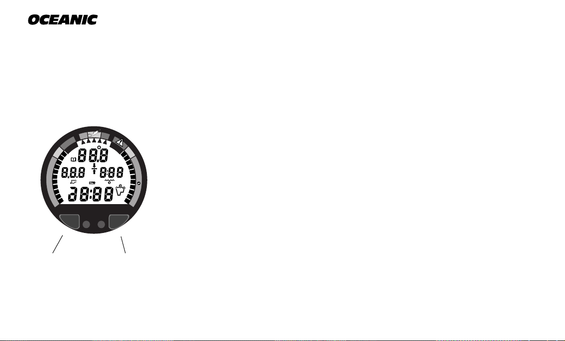
INTERACTIVE CONTROL CONSOLE
Fig. 1 - Interactive
Control Console
2
SelectAdvance
The Interactive Control Console consisting of the Advance (Left) button and
Select (Right) button (Fig. 1) allows you to select various display options and
access specific information when you choose to see it. The buttons can be
pressed repeatedly, or held in to scroll.
INFORMATIONAL DISPLAYS
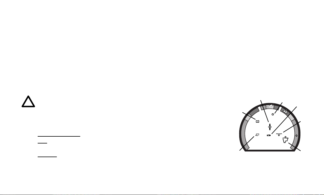
Operational modes and status information are visually represented numerically and/or graphically and can be understood at a glance with the aide of universal icons (Fig. 2) that identify and bring quick focus to the displays. Segmented bar graphs will show how close you are to critical limits.
Each Data Plus 2 numeric and graphic display represents a unique
piece of information. It is imperative that you understand the formats, ranges, and values of the information represented to avoid any
possible misunderstanding that could result in error.
Data Plus 2
a. Operating Mode
b. Elapsed Dive Time
c. Low Battery
d. Temperature
e. Deco Stop
f. Log
g. Maximum Depth
NOTE: Throughout this owner's guide reference is made to the
term ''breathing gas'. The rational being that the Data Plus 2
can be used for 'air' dives or 'nitrox' dives. For clarity these
terms are defined as -
Breathing Gas - the gaseous mixture breathed during a dive.
Air - a breathing gas that contains approximately 21% oxygen
and 79% nitrogen (nature's common nitrogen-oxygen mixture).
Nitrox - a nitrogen-oxygen breathing gas that contains a higher
fraction of oxygen (22 to 50%) than air.
e
f
O
C
E
D
.
Z
.
C
O
C
E
D
O
N
d
O
2
g
Fig. 2 - Universal Icons
c
C
.
Z
.
b
O
2
a
3
®
O
C
E
D
.
Z
.
C
O
C
E
D
O
N
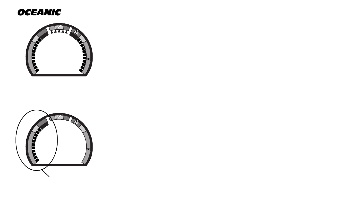
Fig. 3 - Bar Graphs
UNIVERSAL GRAPHIC DIVER INTERFACE
C
.
Z
.
O
2
Three bar graphs referred to as the Universal Graphic Diver Interface™ appear
around the perimeter of the screen (Fig. 3). These segmented bar graphs are
located next to green, yellow, and red color coded portions of the peripheral
decal that denote normal, caution, and danger zones, respectively.
™
When underwater, you can quickly focus on the bar graphs to make sure that
they are in the green. You can quickly verify that you're not getting too close
to the no decompression limit or the limit for exposure to oxygen (accumulation), or ascending too fast.
O
C
E
D
.
Z
.
C
O
C
E
D
O
N
Fig. 4 - Tissue Loading
Bar Graph
4
Tissue Loading Bar Graph
C
.
Z
.
The Tissue Loading Bar Graph™ (TLBG) represents nitrogen loading (Fig. 4),
showing your relative no decompression or decompression status. As your
™
depth and elapsed dive time increase, segments will add to the graph begin-
O
2
ning in the lower left portion of the screen. As you ascend to shallower depths,
this bar graph will begin to recede, indicating that additional no decompression time is allowed for multilevel diving.
The Tissue Loading Bar Graph monitors 12 different nitrogen compartments
simultaneously and displays the one that is in control of your dive. It is divided into a green No Decompression zone (NO DECO), a yellow Caution zone
(C.Z.), and a red Decompression zone (DECO). The bar graph gives a visual
representation of just how close you are to the no decompression limit with a
yellow Caution (C.Z.) Zone.
This Caution Zone portion of the bar graph allows you to make a decision regarding safety stop duration or necessity. While you cannot provide a guarantee against the occurrence of decompression sickness, you may choose your
own personal zone of caution based upon age, physique, excessive weight, etc.,
to reduce the statistical risk.
The Tissue Loading Bar Graph also assists you with managing decompression
(explained later) by filling a large red 'ceiling stop required' segment.
The Tissue Loading Bar Graph™ has been garanted U.S. Patent No. 4,882,687.
Data Plus 2
Oxygen Accumulation (O2) Bar Graph
NOTE: Displays associated with oxygen and the O2 bar graph
will only appear if FO2 has been set at a value other than 'Air'.
The Oxygen Accumulation (O2) Bar Graph (Fig. 5) represents oxygen loading,
your relative oxygen tolerance dosage (OTU), showing the maximum of either
per dive accumulated oxygen, or 24 hour period accumulated oxygen. As your
exposure (accumulation of oxygen) increases during the dive, segments will
add to the bar graph starting in the lower right portion of the screen. As oxy-
O
C
E
D
.
Z
.
C
O
C
E
D
O
N
C
.
Z
.
O
2
Fig. 5 - Oxygen Accumulation
(O2) Bar Graph
5
®
gen loading decreases, the bar graph will begin to recede, indicating that additional exposure (accumulation) is allowed for that dive, and 24 hour period.
Segments = Speed (rate)
0 = 0 - 20 fpm (0 - 6 mpm)
1 = 21 - 30 fpm (6.5 - 9 mpm)
2 = 31 - 40 fpm (9.5 - 12 mpm)
3 = 41 - 50 fpm (12.5 - 15 mpm)
4 = 51 - 60 fpm (15.5 - 18 mpm)
5 = 61+ fpm (18.5+ mpm)
(when 5, all will flash)
O
C
E
D
.
Z
.
C
O
C
E
D
O
N
C
.
Z
.
O
2
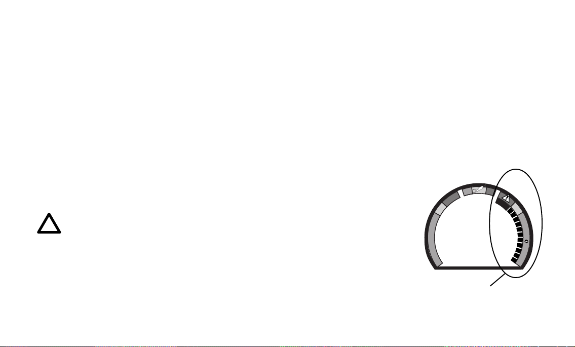
Fig. 6 - Variable Ascent
Rate Indicator
6
The O2 bar graph also assists you with managing high partial pressure of oxygen (PO2) by flashing the large red Danger zone segment as a warning when
the level of PO2 exceeds the maximum allowed limit of 1.60 ATA.
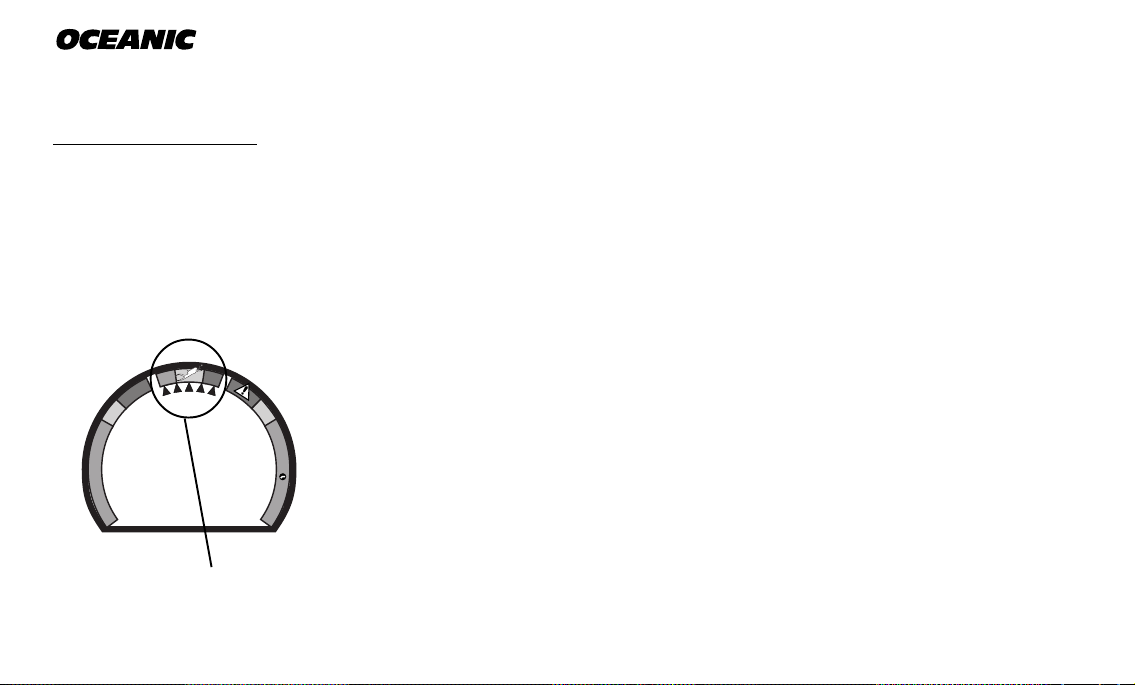
Variable Ascent Rate Indicator
™
The Variable Ascent Rate Indicator™ (VARI), located along the top of the
screen (Fig. 6), is provided to help you to avoid excessive ascent rates by providing a visual representation of ascent speed, rather than just showing that
you are ascending too fast. The Variable Ascent Rate Indicator has been
granted U.S. Patent no. 5,156,055.
The 5 triangular segments of the bar graph, located beside green, yellow, and
red reference zones, appear beginning from the left and may be considered an
ascent rate speedometer. Green is a 'normal' rate, yellow is a 'caution' rate,
and red is 'Too Fast'.
In the event that your ascent rate exceeds the maximum recommended rate of
60 feet (18 meters) per minute, the bar graph segments will enter the red zone
and all 5 segments will flash once per second until your ascent speed is slowed.
If this occurs, you should immediately slow your ascent.
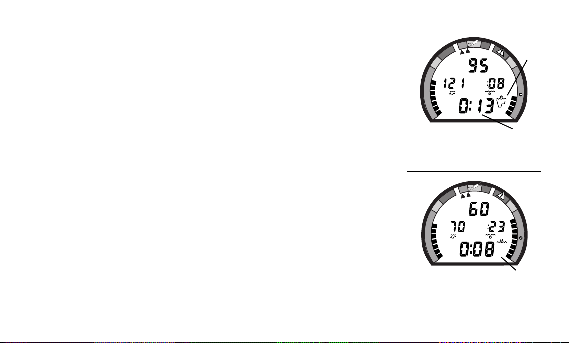
DIVE TIME REMAINING
One of the most important pieces of information on the Data Plus 2 is the patented Dive Time Remaining numeric display. To numerically display Dive Time
Remaining, the Data Plus 2 constantly monitors two critical pieces of information; no decompression status and oxygen accumulation status. The Dive Time
Remaining display will indicate the time that is more critical for you at that particular moment (i.e.; whichever time is the least amount available of the two).
The time being displayed is identified by the No Decompression Dive Time icon
(Fig. 7a), or the O2 Time icon (Fig. 8a). This unique feature has been granted
U.S. Patent No. 4,586,136.
No Decompression Dive Time Remaining
No Decompression Dive Time Remaining is the maximum amount of time that
you can stay at your present depth before entering a decompression situation.
It is calculated based on the amount of nitrogen absorbed by twelve hypothetical tissue compartments. The rates each of these compartments absorb and release nitrogen is mathematically modeled and compared against a maximum allowable nitrogen level. Whichever one of the twelve is closest to this maximum
level is the controlling compartment for that depth. Its resulting value will be
displayed numerically (Fig. 7b) along with the No Decompression Dive icon and
graphically as the Tissue Loading Bar Graph.
Data Plus 2
O
C
E
D
.
Z
.
C
O
C
E
D
O
N
FT
MAX
FT
Fig. 7 - Dive Time Remaining
(No Deco Time is Less)
O
C
E
D
.
Z
.
C
O
C
E
D
O
N
FT
MAX
FT
O
Fig. 8 - Dive Time Remaining
(O2 Accum Time is Less)
a
C
.
Z
.
O
2
b
C
.
Z
.
O
2
2
a
7

®
O
C
E
D
.
Z
.
C
O
C
E
D
O
N
FT
MAX
C
.
Z
.
FT
O
2
O
2
a
Fig. 9 - O2 Time Remaining
As you ascend from depth following a dive that has approached the no decompression limit, the Tissue Loading Bar Graph will recede as control shifts to
slower compartments. This is a feature of the decompression model that is the
basis for multilevel diving, one of the most important advantages the Data
Plus 2 offers.
The no decompression algorithm is based upon Haldane’s theory using maximum allowable nitrogen levels developed by Merrill Spencer. Repetitive diving
control is based upon experiments designed and conducted by Dr. Ray Rogers
and Dr. Michael Powell in 1987. Diving Science and Technology® (DSAT), a
corporate affiliate of PADI®, commissioned these experiments.
Oxygen Accumulation Time Remaining
Oxygen accumulation (exposure) during a dive, or 24 hour period, appears
graphically as the Oxygen Accumulation (O2) Bar Graph. As time remaining
before reaching the oxygen exposure limit decreases, segments are added to
the O2 bar graph. When the amount of time remaining before reaching the
oxygen limit becomes less than the No Decompression Dive Time Remaining,
calculations for the current depth will be controlled by oxygen. Oxygen Time
Remaining will then appear as the main numeric time display (Fig. 9a) as signified by the O2 Time icon appearing to the right of the display. As oxygen accumulation continues to increase, the O2 bar graph will enter the yellow Caution Zone (described later).
8
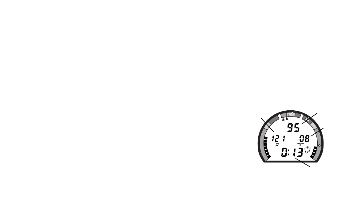
ALPHA/NUMERIC DISPLAYS
Depth Displays
During a dive, CurrentDepth and Maximum Depth reached during that
dive are displayed from 0 to 330 feet (99.5 meters) in 1 foot (.5 meter) increments (Fig. 10 a & b).
During a Decompression Dive, the required Ceiling Stop Depth is displayed
from 60 to 10 feet (20 to 3 meters) in 10 foot (3 meter) increments.
Time Displays (Fig. 10 c & d) are shown in hour:minute format (i.e., 1:02
represents one hour and two minutes, not 102 minutes!). The colon that separates hours and minutes blinks once per second when the display is indicating
real time such as elapsed Surface Time, Elapsed Dive Time, or Time of Day.
Dive Time Available, Dive Time Remaining, Decompression Stop Time, Total
Ascent Time required, Time to Fly, or Desaturation Time are calculated projections of time and use a solid (non-blinking) colon to indicate that they are
counting down, rather than up.
Data Plus 2
b
O
C
E
D
.
Z
.
C
O
C
E
D
O
N
FT
MAX
a
C
.
Z
d
.
FT
O
2
Depth and Time displays will be illustrated and described in more detail as applicable for each of the operating modes.
c
Fig. 10 - Depth & Time
9

®
Responsible
Ambient Temperatures from 0° to 99°F (-9 to 60°C) are displayed when the
Advance (Left) button is pressed while in the Surface Mode or in a dive mode.
BACKLIGHT FEATURE
In addition to using a high contrast LCD for easy readability in low light conditions, the backlight features evenly illuminate the full display.
Smart Glo™, the surface mode backlight, senses the intensity of light that is
passing through the small ports located between the control buttons. If a low
level of light is sensed, the Smart Glo™ backlight will activate and illuminate
the display for button depression time plus 10 seconds when either button is
pressed.
Oceanglo®, the dive mode backlight, will illuminate the display for button depression time plus 5 seconds when the Select (Right) control button is pressed.
Additional illumination time can be obtained by pressing the button again.
NOTE: Extensive use of the backlight reduces estimated battery life. The backlight will not activate during a 'low battery
condition', or when downloading data to a PC.
10

OPERATING TEMPERATURE
The Data Plus 2 will operate in almost any temperature diving environment in
the world between 0 and 140 °F (-9 and 60 °C).
At extremely low temperatures, the LCD may become sluggish, but this will
not affect it's accuracy. If stored or transported in extremely low temperature
areas (below freezing), you should warm the module and its battery with body
heat before diving.
Even though the Data Plus 2 will operate in this wide range of temperatures,
it is possible to damage the electronics if left exposed to direct sunlight, or in a hot confined space (like a car trunk). After the dive, cover
the Data Plus 2 and keep it out of the sun.
If inadvertently left in the direct sunlight for a long period, the LCD display
may become totally black. If this occurs, immediately immerse the Data Plus 2
in water. The display should recover its normal appearance after a few minutes.
Data Plus 2
R
E
S
P
O
N
R
E
V
I
D
E
S
L
I
B
Damage from excess heat, or cold, is not covered by the Data Plus 2
two year limited warranty.
Be a -
RESPONSIBLE DIVER
at all times.
11

®
WARNINGS and SAFETY RECOMMENDATIONS
• Inspect your Data Plus 2 prior to every dive, checking for any signs of the entrance of moisture, damage to the housing, or damage to the LCD display. If these or other signs of damage are found, return the unit to an Authorized Oceanic Dealer. DO NOT attempt to use it
until it has received factory service.
• Oceanic advocates responsible diving practices consistent with your individual level of formal training and experience, and does not recommend decompression diving or diving below
130 feet (39 m).
• Always carry primary and backup dive lights when conducting dives that could include low
light situations.
• You should never, under any circumstances, swap your computer with another unit between
dives, or share your computer with another diver underwater. It is impossible for two divers
to stay precisely together underwater, and your computer's dive profile tracking of previous
dives will be pertinent to you only. Nitrogen and oxygen loading of a second user may be significantly different and thus swapping dive computers could lead to inaccurate and potentially dangerous predictions of decompression and oxygen accumulation status. This rule
applies to the use of all dive computers, but is especially important when using the
DataPlus2, due to the personal information it provides.
12

Data Plus 2
ACTIVATION
and
SETUP
refer to page 21 for - WARNINGS and SAFETY RECOMMENDATIONS
13
®
N
O
D
E
C
O
C
.
Z
.
D
E
C
O
C
.
Z
.
O
2
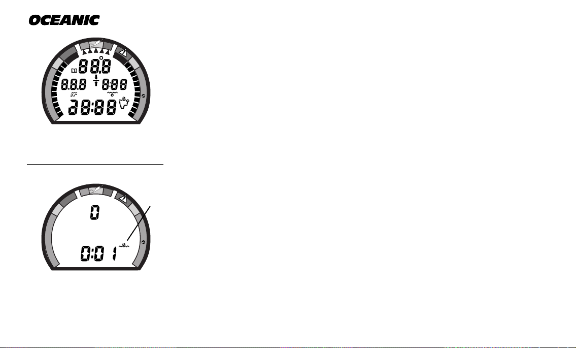
ACTIVATION
O
C
E
D
.
Z
.
C
M
O
C
E
D
O
N
FT
MAX
M
FT
MAX
C
.
Z
.
To activate the Data Plus 2, press the Select (Right) button once and release.
The Data Plus 2 will immediately enter Diagnostic Mode, displaying all “8’s”
O
2
(Fig. 11), followed by “dashes”, and a countdown from 9 to 0. While conducting diagnostics, the display is illuminated by the Smart Glo™ backlight as the
O
2
Data Plus 2 checks its display functions and battery voltage to ensure that everything is working correctly.
Fig. 11 - Diagnostic Mode
Fig. 12 - Surface Mode
14
Upon activation, the Data Plus 2 will also check the ambient barometric pressure, and calibrate its present depth as zero. At elevations of 2,000 ft. (610 m)
or higher, it will recalibrate itself to measure depth in feet of fresh water instead of feet of sea water.
a
If no dive is made within 2 hours after initial activation, the Data Plus 2 will
automatically deactivate to conserve its battery power. Always check the
display before entering the water to ensure that it is activated.
SURFACE MODE
Surface Mode, identified by the Surface Time icon (Fig. 12a), immediately follows Diagnostic Mode after initial activation. Information displayed includes
the Dive Number '0' (no dive made yet) and Surface Time with flashing colon.

If battery voltage is below the level sufficient for a day's operation, the Battery
icon will be displayed, flashing (Fig. 13a). Below 15% of rated voltage, all
graphic displays will shut off except the Battery icon that will flash for 5 seconds, then the unit will shutdown.
MAIN MODE MENU
While on the surface, you can access Temperature/Date/Time mode, FO2 Set
mode, Pre Dive Planning Sequence, Time to Fly/Desaturate, Log mode, and
Set mode. These are described later.
The menu structure of the Set Mode enables you to -
• turn the Dive Mode Alternate display feature On/Off.
• set Year/Month/Day
• select Hour Format (12 or 24 hour).
• set Hour/Minute.
• select the Dive Profile Sampling Rate (for PC download data).
• select Units of Measure (Imperial or Metric).
• turn the FO2 Default feature On/Off.
• initiate download of data (External Access).
Data Plus 2
O
C
E
D
.
Z
.
C
O
C
E
D
O
N
a
C
.
Z
.
O
2
Before going diving, enter settings that will be common for each of your dives
(e.g., Date, Time, Units of Measure, etc.). Setting the FO2 value for a nitrox
mix is a 'pre dive' setting that is entered before nitrox dives.
Fig. 13 - Low Battery
15
®
ENTERING SETTINGS
• The Advance (Left) button is used to gain access to settings.
• The Select (Right) button is used to toggle between, or scroll through, the
individual set points available for each of the settings.
• The Advance (Left) button is then used to accept and save the set point
and revert to Surface Mode, or continue to the next setting.
• See page 22 for a 'Summary of Access to Set Modes' that also
notes 'settings entered by the factory'.
NOTE: While in the Set Mode, if neither button is pressed, the
unit will automatically revert to Surface Mode in 2 minutes.
O
C
E
D
.
Z
.
C
O
C
E
D
O
N
Fig. 14 - Set Alternate
16
C
.
Z
.
'OFF' - Dive Modes will display Max Depth and Elapsed Dive Time
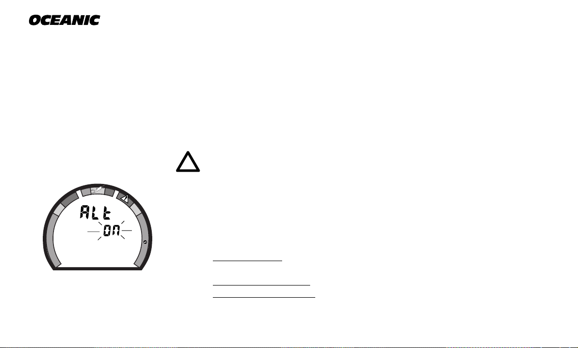
TO SET: ALTERNATE ON/OFF
O
'ON' - Max Depth and Elapsed Dive Time are 'accessed' by pressing button
2
• press BOTH buttons simultaneously, while in Surface Mode
• 'Alt' appears with 'On', or 'Off', flashing (Fig. 14)
• press Select (Right) button to toggle between 'On' and 'Off'
• press Advance (Left) button to accept the setting displayed, and either -
• revert to Surface Mode (this setting changed)
• advance to Set:Year (this setting not changed)
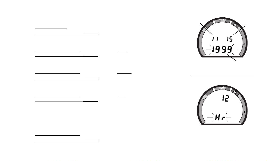
TO SET: DATE//HOUR FORMAT//TIME
• press BOTH buttons simultaneously, while in Surface Mode
• press Advance (Left) button 1 time
• the Date appears with the Year setting flashing (Fig. 15a)
• press Select (Right) button until the correct Year appears
• press Advance (Left) button 1 time to accept the setting displayed
• the Month setting flashes (Fig. 15b)
Data Plus 2
b
O
C
E
D
.
Z
.
C
O
C
E
D
O
N
c
C
.
Z
.
O
2
a
• press Select (Right) button until the correct Month appears.
• press Advance (Left) button 1 time to accept the setting displayed
• the Day setting flashes (Fig. 15c)
• press Select (Right) button until the correct Day appears.
• press Advance (Left) button 1 time to accept the setting displayed
• the Hour Format appears flashing (Fig. 16)
• 12 Hr format = 12: Am to 11: Pm
• 24 Hr format = 0: to 23: (hours)
• press Select (Right) button to toggle between '12' and '24'
• press Advance (Left) button 1 time to accept the setting displayed
Fig. 15 - Set Date
O
C
E
D
.
Z
.
C
O
C
E
D
O
N
C
.
Z
.
O
2
Fig. 16 - Set Hour Format
17
®
FT
N
O
D
E
C
O
C
.
Z
.
D
E
C
O
C
.
Z
.
O
2
O
C
E
D
.
Z
.
C
O
C
E
D
O
N
a
Fig. 17 - Set Time
Fig. 18 - Set Sampling Rate
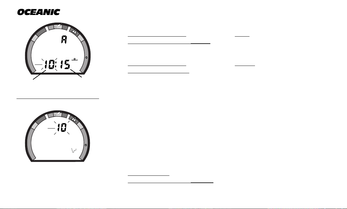
• the Time appears with the Hour setting flashing (Fig. 17a)
C
.
Z
M
.
O
2
• press Select (Right) button until the correct Hour appears.
• press Advance (Left) button 1 time to accept the setting displayed
• the Minute setting flashes (Fig. 17b)
• press Select (Right) button until the correct Minute appears.
• press Advance (Left) button to accept the setting displayed, and either -
b
• revert to Surface Mode (date/time settings changed)
• advance to Set: Sampling Rate (Date/Time settings not changed)
TO SET: SAMPLING RATE
Sampling Rate is the Time, or Depth, interval at which data samples will be
recorded for subsequent download to the OceanLog™ PC software program. It
has 'no effect' upon displayed data or data stored in the unit's viewable Log.
Rates available are 2 FT (.5M), 5 FT (1.5 M), 10 FT (3 M), 2 SEC, 5 SEC, 10
SEC, 15 SEC, 20 SEC, 25 SEC, 30 SEC. Lower rates = more samples and
more memory used per dive (e.g., fewer dives stored for download).
• press BOTH buttons simultaneously, while in Surface Mode
• press Advance (Left) button 7 times
• the Rate setting appears flashing (Fig. 18)
18
• press Select (Right) button until the desired Rate appears.
• press Advance (Left) button to accept the setting displayed, and either -
• revert to Surface Mode (this setting changed)
• advance to Set: Unit (this setting not changed)
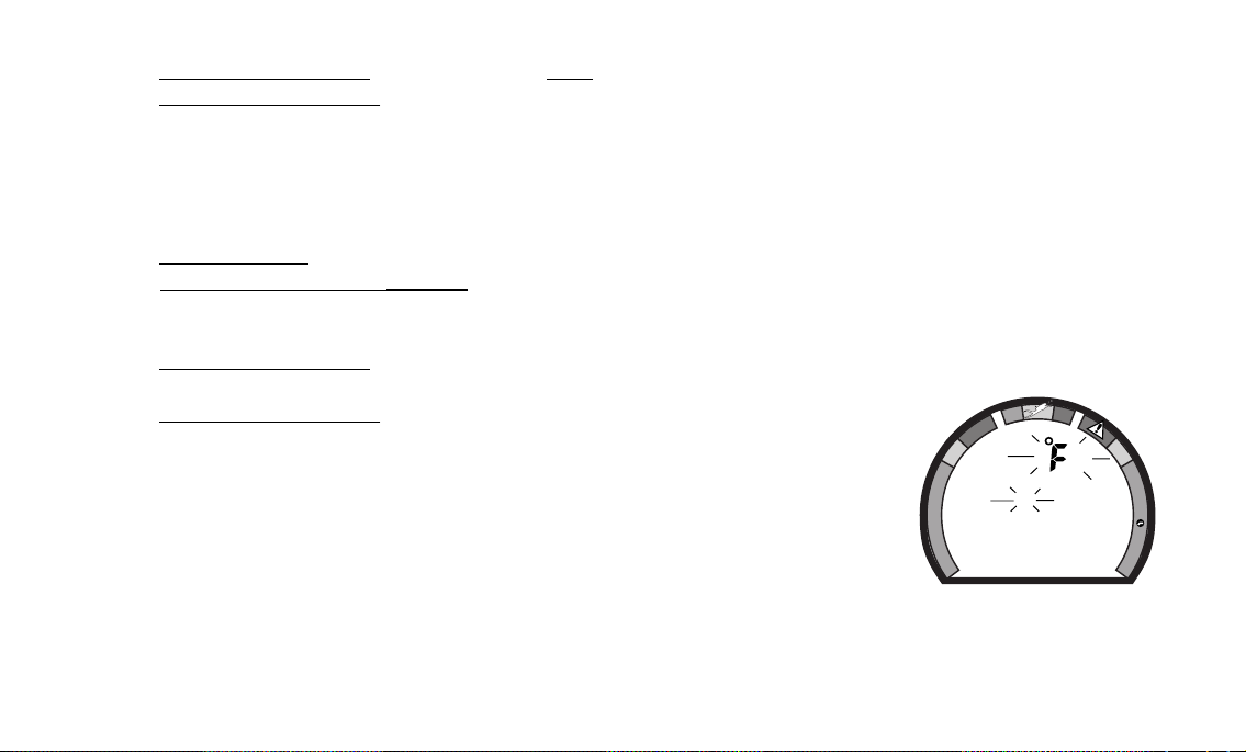
TO SET: UNITS OF MEASURE
• press BOTH buttons simultaneously, while in Surface Mode
• press Advance (Left) button 8 times
• the Units of Measure icons appear flashing (Fig. 19)
• press Select (Right) button to toggle between 'Imperial' (FT/°F) and
'Metric' (M/°C)
• press Advance (Left) button to accept the setting displayed, and either -
• revert to Surface Mode (this setting changed)
• advance to Set: FO2 Default (this setting not changed)
TO SET: FO2 50% DEFAULT ON/OFF
'Off' - FO2 value set point remains at % set
'On' - FO2 value set point reverts to 50% after dives
Data Plus 2
O
C
E
D
.
Z
.
C
O
C
E
D
O
N
FT
FT
C
.
Z
.
O
2
(The FO2 Default feature is described on page 25.)
Fig. 19 - Set Units
19
 Loading...