

Page 1

TM
Mask / Dive Computer
Operating Manual
Page 2
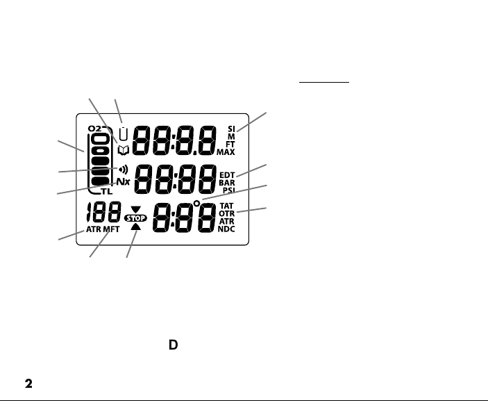
Components:
c
b
a
l
k
j
i
h
a. TLBG / O2BG
b. Icon - Log Mode
c. Icon - Low Battery
d
d. Icons - SI (Surface Interval)
- FT or M (Depth)
- MAX
e. Icons - EDT (Elapsed Dive Time)
e
f
g
- BAR or PSI (Pressure)
f. Icon - Degrees (Temperature)
g. Icons - TAT (Total Ascent Time)
- OTR (O2 Time Remaining)
- ATR (Air Time Remaining)
- NDC (No Deco Time Remaining)
h. Icon - Descend (arrow)
- Stop (bar)
- Ascend (arrow)
i. Icons - M or FT (Depth)
j. Icon - ATR (Air Time Remaining)
DataMask FULL LCD
2
Page 3

CONTENTS
FULL LCD ......................................................................................................................................................................... 2
WARRANTY, NOTICES, DECOMPRESSION MODEL ....................................................................................................7
FCC ID ............................................................................................................................................................................... 8
INTRODUCTION AND GENERAL FEATURES AND DISPLAYS .................................................................................... 9
General Interface and Human Factors ................................................................................................................. 10
Mask Optics and Display Interface ....................................................................................................................... 11
Environmental Capabilities ................................................................................................................................... 11
INTERACTIVE CONTROL CONSOLE ..................................................................................................................... 12
OPERATING MODE STRUCTURE ........................................................................................................................... 13
AUDIBLE ALARM ...................................................................................................................................................... 14
BACKLIGHT .............................................................................................................................................................. 16
POWER SUPPLY ...................................................................................................................................................... 17
BAR GRAPH .............................................................................................................................................................. 18
PC INTERFACE ......................................................................................................................................................... 21
ALPHA / NUMERIC DISPLAYS ................................................................................................................................ 22
Tank Pressure Display .......................................................................................................................................... 22
Depth Displays ...................................................................................................................................................... 22
Air Time Remaining Display ................................................................................................................................. 23
Time, Date, and Temperature Displays ................................................................................................................ 23
SURFACE SEQUENCE AND OPERATING MODES ..................................................................................................... 25
OPERATING MODES ................................................................................................................................................ 26
SURFACE MODE ...................................................................................................................................................... 26
NOR (Normal) Surface Main Display ................................................................................................................... 27
NOR Surface Main Button Operations ................................................................................................................. 28
Transmitter Low Battery .................................................................................................................................... 29
SET MODES .............................................................................................................................................................. 29
SET G GROUP (BACKLIGHT) ................................................................................................................................. 30
Set Backlight Level ............................................................................................................................................... 31
3
Page 4

CONTENTS (continued)
SET F GROUP (FO2) ................................................................................................................................................ 32
Set FO2 for NOR Nitrox Dives ............................................................................................................................. 32
Set FO2 ................................................................................................................................................................ 34
Set FO2 50% Default ........................................................................................................................................... 35
SET A GROUP (NOR/GAU ALARMS) ...................................................................................................................... 35
Set Audible Alarm ................................................................................................................................................. 36
Set Depth Alarm ................................................................................................................................................... 37
Set EDT (Elapsed Dive Time) Alarm ................................................................................................................... 38
Set TLBG (Tissue Loading Bar Graph) Alarm ...................................................................................................... 39
Set DTR (Dive Time Remaining) Alarm................................................................................................................ 40
Set Turn Pressure Alarm ...................................................................................................................................... 41
Set End Pressure Alarm ....................................................................................................................................... 42
Set PO2 Alarm ...................................................................................................................................................... 43
SET U GROUP (UTILITIES) ...................................................................................................................................... 43
Set Wet Activation ................................................................................................................................................ 44
Set Units ............................................................................................................................................................... 45
Set NOR Safety Stop ............................................................................................................................................ 46
Set Conservative Factor ....................................................................................................................................... 47
Set Sampling Rate ................................................................................................................................................ 48
Set Transmitter Link Code .................................................................................................................................... 49
SET T GROUP (TIME/DATE) .................................................................................................................................... 51
Set Hour Format ................................................................................................................................................... 51
Set Time ................................................................................................................................................................ 52
Set Date ................................................................................................................................................................ 53
SERIAL NUMBER (DATAMASK) .............................................................................................................................. 54
NOR SURF ALT DISPLAYS 1 AND 2 ....................................................................................................................... 55
NOR PLAN MODE ..................................................................................................................................................... 56
FLY MODE ................................................................................................................................................................. 59
SAT MODE (DESATURATE) ..................................................................................................................................... 60
NOR/GAU LOG MODE ............................................................................................................................................. 62
NOR/GAU HISTORY MODE ...................................................................................................................................... 66
4
Page 5

CONTENTS (continued)
OVERVIEW OF DIVE MODE INFORMATION ............................................................................................................... 69
POSITIONING A TRANSMITTER AND MASK ......................................................................................................... 70
Link Interruption Underwater ................................................................................................................................ 70
DIVE TIME REMAINING (DTR) ................................................................................................................................. 71
No Decompression Dive Time Remaining (NDC) ................................................................................................ 72
Oxygen Accumulation Time Remaining (OTR) .................................................................................................... 73
Air Time Remaining (ATR) .................................................................................................................................... 74
Air Time Remaining Alarm .................................................................................................................................... 75
ASCENT RATE ALARM ............................................................................................................................................ 76
TURN AND END PRESSURE ALARMS ................................................................................................................... 76
CONTROL OF DISPLAYS ......................................................................................................................................... 76
WET CONTACTS ....................................................................................................................................................... 77
NOR (NORMAL) TYPE DIVE MODES ........................................................................................................................... 79
NOR DIVE MAIN AND ALT DISPLAYS ..................................................................................................................... 80
SETTING BACKLIGHT LEVEL ................................................................................................................................. 82
NOR DIVE NO DECO SAFETY STOP ...................................................................................................................... 83
DECOMPRESSION DIVE MODE .............................................................................................................................. 85
VIOLATION MODES .................................................................................................................................................. 88
HIGH PO2 .................................................................................................................................................................. 93
HIGH O2 .................................................................................................................................................................... 94
NOR POST DIVE MODES .............................................................................................................................................. 97
TRANSITION PERIOD .............................................................................................................................................. 98
AFTER THE TRANSITION PERIOD ....................................................................................................................... 100
GAUGE OPERATING MODE ....................................................................................................................................... 101
GAU SURFACE MAIN AND ALT DISPLAYS .......................................................................................................... 102
GAU DIVE MAIN AND ALT DISPLAYS ................................................................................................................... 104
5
Page 6

CONTENTS (continued)
FREE DIVE OPERATING MODE ................................................................................................................................. 107
FREE SURFACE MAIN AND ALT DISPLAYS ........................................................................................................ 109
FREE SURFACE SET MENU .................................................................................................................................. 111
FREE Surface CDT (Count Down Timer) Status ............................................................................................... 111
Set FREE CDT ................................................................................................................................................... 112
FREE Dive EDT (Elapsed Dive Time) Alarm ..................................................................................................... 113
Set FREE EDT Alarm ......................................................................................................................................... 113
FREE Dive Depth Alarms ................................................................................................................................... 114
Set FREE Dive Depth Alarms ............................................................................................................................. 114
FREE DIVE MAIN, CDT, AND ALT DISPLAYS ....................................................................................................... 117
FREE DIVE ALARMS .............................................................................................................................................. 119
ENTRY INTO DECO DURING A FREE DIVE ......................................................................................................... 121
OCEANIC WORLDWIDE (INTERNATIONAL DISTRIBUTORS) ............................................................................ 122
REFERENCE ................................................................................................................................................................. 123
UPLOADING SETTINGS AND DOWNLOADING DATA ........................................................................................ 124
PC Compatibility Requirements .......................................................................................................................... 125
MASK PREPARATION AND USE ........................................................................................................................... 126
CARE AND CLEANING ........................................................................................................................................... 127
INSPECTIONS AND SERVICE ............................................................................................................................... 127
BATTERY REPLACEMENT .................................................................................................................................... 130
INSTALLING A TRANSMITTER ON A REGULATOR ............................................................................................ 135
TRANSMITTER COMPATIBILITY WITH NITROX .................................................................................................. 135
ALTITUDE SENSING AND ADJUSTMENT ............................................................................................................ 136
CHARTS OF NO DECOMPRESSION LIMITS AT ALTITUDE ................................................................................ 137
CHART OF OXYGEN EXPOSURE LIMITS ............................................................................................................ 138
SPECIFICATIONS ................................................................................................................................................... 139
ABBREVIATIONS .................................................................................................................................................... 146
INSPECTION/ SERVICE RECORD ......................................................................................................................... 147
Pay special attention to items marked
with this Warning symbol.
6
Page 7
LIMITED TWO-YEAR WARRANTY
For details and online registration, visit www.OceanicWorldwide.com
COPYRIGHT NOTICE
This Operating Manual is copyrighted, all rights are reserved. It may not, in whole or in part, be copied, photocopied,
reproduced, translated, or reduced to any electronic medium or machine readable form without prior consent in writing
from Oceanic / 2002 Design.
DataMask Operating Manual, Doc. No. 12-2736
TRADEMARK, TRADE NAME, AND SERVICE MARK NOTICE
Oceanic, the Oceanic logotype, DataMask, the DataMask logo, Air Time Remaining (ATR), Diver Replaceable Batteries,
Graphic Diver Interface, Tissue Loading Bar Graph (TLBG), Pre Dive Planning Sequence (PDPS), Set Point, Control
Console, Turn Gas Alarm, OceanLog, and Digital Optic System are all registered and unregistered trademarks, trade
names, and service marks of Oceanic. All rights are reserved.
PATENT NOTICE
U.S. Patents have been issued, or applied for, to protect the following design features:
Air Time Remaining (U.S. Patent no. 4,586,136 and 6,543,444) and Data Sensing and Processing Device (U.S. Patent
no. 4,882,678). Set TLBG Alarm and other patents pending. User Setable Display (U.S. Patent no. 5,845,235) is
owned by Suunto Oy (Finland).
DECOMPRESSION MODEL
The programs within the DataMask simulate the absorption of nitrogen into the body by using a mathematical model.
This model is merely a way to apply a limited set of data to a large range of experiences. The DataMask dive computer
model is based upon the latest research and experiments in decompression theory.
as using the U.S. Navy (or other) No Decompression Tables, is no guarantee of avoiding decom-
pression sickness, i.e. the bends.
No machine can predict how your body will react to a particular dive profile.
© 2002 Design, 2007
San Leandro, CA USA 94577
Still, using the DataMask, just
Every divers physiology is different, and can even vary from day to day.
7
Page 8
WARNING: If your DataMask stops working for any reason, it is
important that you have anticipated this possibility and are pre-
pared for it. This is an important reason for not pushing the no
decompression and oxygen exposure limits, and a critical reason
to avoid entering decompression. If you dive in situations where
your trip would be ruined or your safety would be jeopardized by
losing the use of your DataMask, a backup instrument system is
highly recommended.
FCC ID: MH8A
FCC COMPLIANCE:
This equipment complies with Part 15 of the FCC Rules. Operation is subject to the following two conditions: 1.) this equipment may not
cause harmful interference, and 2.) this equipment must accept any interference received, including interference that may cause undesired
operation.
FCC INTERFERENCE STATEMENT:
This equipment has been tested and found to comply with the limits for an Intentional Radiator, a Class B Digital Device, pursuant to Part
15 of FCC Rules, Title 47 of the Code of Federal Regulations. These rules are designed to provide reasonable protection against harmful
interference in a commercial or residential installation. This equipment generates, uses and can radiate radio frequency energy and, if
not installed and used in accordance with the instructions, may cause harmful interference to radio communications.
There is no guarantee that interference will not occur in a particular installation. If this equipment does cause interference to radio or
television reception, which can be determined by turning the equipment off and on, the user is encouraged to try to correct the
interference by one or more of the following measures:
Reorient or relocate the receiving antenna.
Increase the separation between the equipment and receiver.
Connect the equipment to an outlet on a circuit different from that to which the receiver is connected.
Consult the dealer or an experienced radio/TV technician.
Warning: Changes or modifications to this unit not expressly approved by Oceanic/2002 Design could
void the user's authority to operate the equipment.
8
Page 9
WARNING: Prior to diving with the DataMask, you must also
read and understand the Oceanic Dive Computer Safety and
Reference Manual, Doc. No. 12-2262, which provides Important
Warnings and Safety Recommendations as well as general
product information.
INTRODUCTION
AND
GENERAL FEATURES AND DISPLAYS
9
Page 10
INTRODUCTION
Welcome to OCEANIC and thank you for choosing the DataMask !
It is extremely important that you read this Operating Manual in sequence and understand
it completely before attempting to use the DataMask as a dive computer.
It is equally important that you read the Oceanic Dive Computer Safety and Reference
Manual (Doc. No. 12-2262) provided with your DataMask. It contains information that
you must become familiar with prior to diving with your DataMask.
Remember that technology is no substitute for common sense, and a dive computer only
provides the person using it with data, not the knowledge to use it.
General Interface and Human Factors
The Mask provides a watertight face seal and comfort level during SCUBA or FREE dives.
The Mask and its components will not interfere with or degrade the user's capability to use
underwater communication or acoustic system headsets that mount over the user's ear(s).
Straps and Strap Adjustments allow for quick and easy donning and doffing of the Mask
as would be done with a typical sport diving Mask.
Mask electronics are activated by manual button operation or by water activation (if set
ON, a predefined user setting).
10
Page 11
A diver who can read his or her instruments with uncorrected vision will be able to read
the Mask display in all the environmental conditions described.
DataMask System components can be located and operated by a diver wearing a 7 mm
thick three finger (lobster claw) wet suit glove. The equipment will not be impaired/
degraded when the diver is wearing a 7 millimeter wet suit or dry suit hood.
Mask Optics and Display Interface
The Display of the Mask is viewed through an integrated Digital Optic System that is
used to display alpha/numeric data and icons/symbols.
After magnification, alpha/numeric characters on the Display can be read by a user who
can read a ½ inch character at a distance of 10" from the eye with uncorrected vision.
NOTE: Characters and symbols (icons) appear as a negative field
which is lighted against a dark background when active and invisible
(dark against a dark background) when not active.
Environmental Capabilities
Functionality is not degraded by exposure to the life cycle environmental profiles and
conditions described. The DataMask meets the manufacturer's environmental test stan-
dards and combined test procedures performed on dive computers and dive masks.
Tests have been conducted to verify performance in the environmental profiles and condi-
tions described.
11
Page 12
Ambient Light Levels
The Mask's display is readable on the surface and while underwater in Ambient Light
Levels ranging from no light to bright light (direct sun). Shading may be required on the
surface in direct sunlight.
Visibility
The Mask's display is readable in external Visibility Conditions ranging from zero to
infinite. It is readable as long as water does not cover the Display Optics. The Mask lens
and Digital Optic System are capable of being prevented from fogging. Water droplets
are prevented from collecting on the Display Optics in wet conditions.
INTERACTIVE CONTROL CONSOLE
The Interactive Control Console consists of 2 Control Buttons that allow you to select mode
options and access specific information. They are also used to link the Transmitter, enter
Settings, activate the Backlight, and acknowledge the Audible Alarm.
Throughout this manual they will be referred to as the A (Top) and S (Side) buttons.
Top = Advance (A) button
Side = Select (S) button
12
Page 13
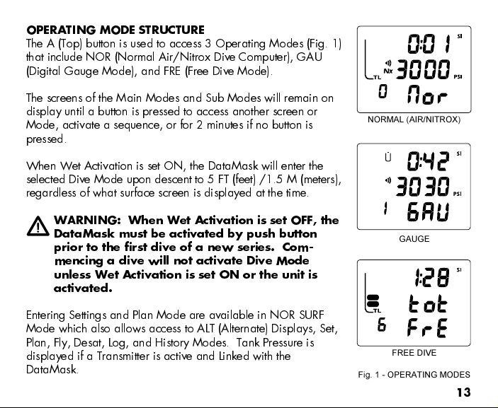
OPERATING MODE STRUCTURE
The A (Top) button is used to access 3 Operating Modes (Fig. 1)
that include NOR (Normal Air/Nitrox Dive Computer), GAU
(Digital Gauge Mode), and FRE (Free Dive Mode).
The screens of the Main Modes and Sub Modes will remain on
display until a button is pressed to access another screen or
Mode, activate a sequence, or for 2 minutes if no button is
pressed.
When Wet Activation is set ON, the DataMask will enter the
selected Dive Mode upon descent to 5 FT (feet) /1.5 M (meters),
regardless of what surface screen is displayed at the time.
WARNING: When Wet Activation is set OFF, the
DataMask must be activated by push button
prior to the first dive of a new series. Com-
mencing a dive will not activate Dive Mode
unless Wet Activation is set ON or the unit is
activated.
Entering Settings and Plan Mode are available in NOR SURF
Mode which also allows access to ALT (Alternate) Displays, Set,
Plan, Fly, Desat, Log, and History Modes. Tank Pressure is
displayed if a Transmitter is active and Linked with the
DataMask.
NORMAL (AIR/NITROX)
GAUGE
FREE DIVE
Fig. 1 - OPERATING MODES
13
Page 14
GAUGE Surface Mode allows access to ALT (Alternate) Displays, Set, Fly, Log, and History
Modes. It also displays Tank Pressure.
FRE Mode allows access to sub modes by first accessing NOR Surface Mode. It does not
display Tank Pressure.
Once a dive is made in GAUGE Mode, the DataMask is locked into that Mode for 24
hours after the dive.
AUDIBLE ALARM
Most warning situations that activate the Audible Alarm while operating in NOR or GAU
Mode cause the DataMask to emit 1 beep per second for 10 seconds, or until the situation
is corrected, or it is acknowledged by momentarily pressing and releasing the A (Top)
button (less than 2 seconds). After being acknowledged and the situation corrected, the
Alarm will sound again upon reentry into the warning situation, or entry into another type
of warning situation.
FRE Dive Mode has its own set of Alarms which emit 3 short beeps either 1 or 3 times
which cannot be acknowledged.
If the Backlight is OFF, it will come ON at any time at the Level set during the time that an
Alarm strikes even when set OFF. It will remain ON until the Alarm condition is corrected
or clears, even if the S (Side) button is pressed in an attempt to turn it OFF.
14
Page 15
Situations that will activate the NOR/GAU 10 second Alarm include -
Air Time Remaining (ATR) at 5 minutes, then again at 0 minutes.
A TR becomes less than No Deco and O2 Time Remaining for 1 minute.
Turn Pressure at the Set Point selected.
End Pressure at the Set Point selected.
Descent deeper than the Max Depth Set Point selected.
Dive Time Remaining at the Set Point selected.
Elapsed Dive Time at the Set Point selected.
PO2 increases to the Set Point selected.
High O2 of 300 OTU (single or daily exposure).
Tissue Loading Bar Graph at the segment Set Point selected.
NOR/GAU Ascent Rate exceeds 60 FPM (18 MPM) when deeper than 60 FT (18 M),
or 30 FPM (9 MPM) at 60 FT (18 M) and shallower.
Loss of the active Transmitter Link signal for more than 15 seconds during a dive.
Entry into Decompression Mode (Deco).
Conditional Violation (above a required Deco Stop Depth for less than 5 minutes).
Delayed Violation (above a required Deco Stop Depth for more than 5 minutes).
Delayed Violation (a Deco Stop Depth greater than 60 FT/18 M is required).
Delayed Violation (Maximum Operating Depth of 330 FT/99.9 M is exceeded).
A single short beep (which cannot be disabled) is emitted for the following -
Upon completion of a Hot Swap battery change.
Change from Delayed to Full Violation 5 minutes after the dive.
15
Page 16
3 short beeps (which cannot be disabled) are emitted for the following -
FREE Dive Elapsed Dive Time Alarm (3 beeps every 30 seconds if set ON).
FREE Dive Depth Alarms 1/2/3 (set sequentially deeper) - each 3 beeps 3 times.
FREE Dive TLBG Alarm (Caution zone, 4 segments) - 3 beeps 3 times.
Entry into Deco during a FREE Dive (Permanent Violation) - 3 beeps 3 times.
FREE Dive Mode Countdown Timer reaches 0:00 - 3 beeps 3 times.
During the following NOR Dive situations, the 10 second Audible Alarm will not turn off
when acknowledged -
Ascending above a required Decompression Ceiling Stop Depth for more than 5
minutes (referred to as a Delayed Violation).
Decompression requires a Ceiling Stop Depth of 70 FT/21 M or deeper.
Being on the Surface for 5 minutes after a Conditional Violation.
BACKLIGHT
When the Backlight is OFF, depressing the S (Side) button will activate the Backlight which
will turn ON upon button depression. The Backlight will be ON, at the Level previously
set, until the S (Side) button is depressed again to turn it OFF.
The Backlight will not be disabled if the S (Side) button is held depressed for any long
time (> 2 seconds) or if a Low Battery Alarm Condition (< 2.50 vdc) is sensed.
If the Backlight is OFF, it will come ON at the Level previously set upon descent on a
dive, during the time that an Alarm strikes, and upon entry into a Set Menu while on
the surface or during a dive, even when set OFF. If the Backlight is ON, it will remain
ON and will not be turned OFF when the S (Side) button is pressed while operating
in the Set Menu.
The Backlight does not operate when the DataMask is connected to a PC.
16
Page 17
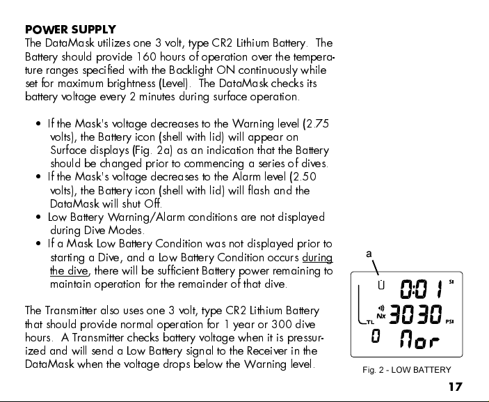
POWER SUPPLY
The DataMask utilizes one 3 volt, type CR2 Lithium Battery. The
Battery should provide 160 hours of operation over the tempera-
ture ranges specified with the Backlight ON continuously while
set for maximum brightness (Level). The DataMask checks its
battery voltage every 2 minutes during surface operation.
If the Mask's voltage decreases to the Warning level (2.75
volts), the Battery icon (shell with lid) will appear on
Surface displays (Fig. 2a) as an indication that the Battery
should be changed prior to commencing a series of dives.
If the Mask's voltage decreases to the Alarm level (2.50
volts), the Battery icon (shell with lid) will flash and the
DataMask will shut Off.
Low Battery Warning/Alarm conditions are not displayed
during Dive Modes.
If a Mask Low Battery Condition was not displayed prior to
starting a Dive, and a Low Battery Condition occurs during
the dive, there will be sufficient Battery power remaining to
maintain operation for the remainder of that dive.
The Transmitter also uses one 3 volt, type CR2 Lithium Battery
that should provide normal operation for 1 year or 300 dive
hours. A Transmitter checks battery voltage when it is pressur-
ized and will send a Low Battery signal to the Receiver in the
DataMask when the voltage drops below the Warning level.
a
Fig. 2 - LOW BATTERY
17
Page 18
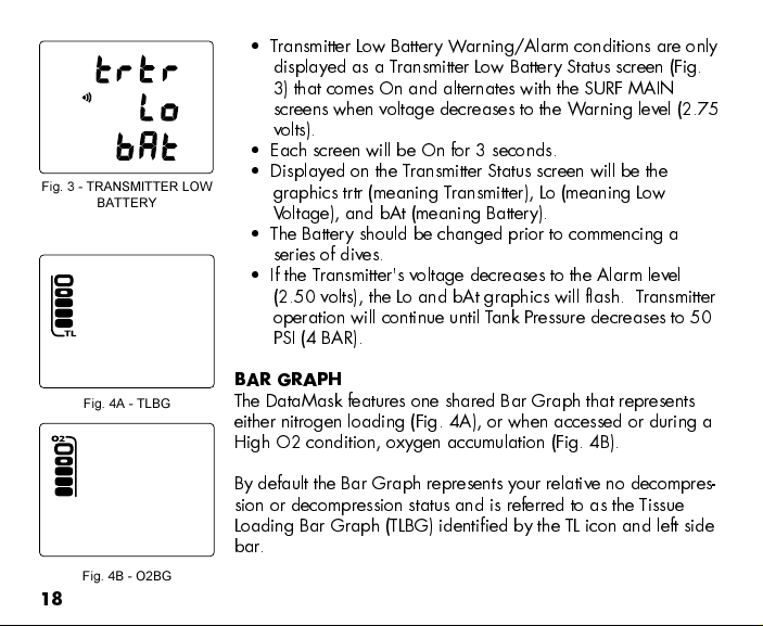
Fig. 3 - TRANSMITTER LOW
BATTERY
Fig. 4A - TLBG
Fig. 4B - O2BG
18
Transmitter Low Battery Warning/Alarm conditions are only
displayed as a Transmitter Low Battery Status screen (Fig.
3) that comes On and alternates with the SURF MAIN
screens when voltage decreases to the Warning level (2.75
volts).
Each screen will be On for 3 seconds.
Displayed on the Transmitter Status screen will be the
graphics trtr (meaning Transmitter), Lo (meaning Low
V oltage), and bAt (meaning Battery).
The Battery should be changed prior to commencing a
series of dives.
If the Transmitter's voltage decreases to the Alarm level
(2.50 volts), the Lo and bAt graphics will flash. Transmitter
operation will continue until Tank Pressure decreases to 50
PSI (4 BAR).
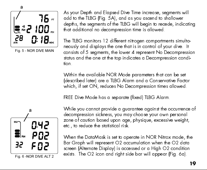
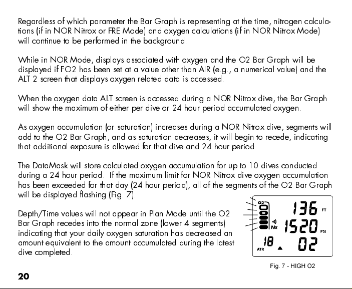
BAR GRAPH
The DataMask features one shared Bar Graph that represents
either nitrogen loading (Fig. 4A), or when accessed or during a
High O2 condition, oxygen accumulation (Fig. 4B).
By default the Bar Graph represents your relative no decompres-
sion or decompression status and is referred to as the Tissue
Loading Bar Graph (TLBG) identified by the TL icon and left side
bar.
Page 19
a
Fig. 5 - NOR DIVE MAIN
As your Depth and Elapsed Dive Time increase, segments will
add to the TLBG (Fig. 5A), and as you ascend to shallower
depths, the segments of the TLBG will begin to recede, indicating
that additional no decompression time is allowed.
The TLBG monitors 12 different nitrogen compartments simulta-
neously and displays the one that is in control of your dive. It
consists of 5 segments, the lower 4 represent No Decompression
status and the one at the top indicates a Decompression condi-
tion.
Within the available NOR Mode parameters that can be set
(described later) are a TLBG Alarm and a Conservative Factor
which, if set ON, reduces No Decompression times allowed.
FREE Dive Mode has a separate (fixed) TLBG Alarm.
a
Fig. 6 -NOR DIVE ALT 2
While you cannot provide a guarantee against the occurrence of
decompression sickness, you may choose your own personal
zone of caution based upon age, physique, excessive weight,
etc., to reduce the statistical risk.
When the DataMask is set to operate in NOR Nitrox mode, the
Bar Graph will represent O2 accumulation when the O2 data
screen (Alternate Display) is accessed or a High O2 condition
exists. The O2 icon and right side bar will appear (Fig. 6a).
19
Page 20
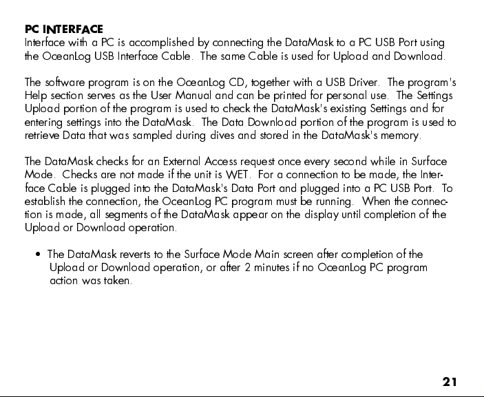
Regardless of which parameter the Bar Graph is representing at the time, nitrogen calcula-
tions (if in NOR Nitrox or FRE Mode) and oxygen calculations (if in NOR Nitrox Mode)
will continue to be performed in the background.
While in NOR Mode, displays associated with oxygen and the O2 Bar Graph will be
displayed if FO2 has been set at a value other than AIR (e.g., a numerical value) and the
ALT 2 screen that displays oxygen related data is accessed.
When the oxygen data ALT screen is accessed during a NOR Nitrox dive, the Bar Graph
will show the maximum of either per dive or 24 hour period accumulated oxygen.
As oxygen accumulation (or saturation) increases during a NOR Nitrox dive, segments will
add to the O2 Bar Graph, and as saturation decreases, it will begin to recede, indicating
that additional exposure is allowed for that dive and 24 hour period.
The DataMask will store calculated oxygen accumulation for up to 10 dives conducted
during a 24 hour period. If the maximum limit for NOR Nitrox dive oxygen accumulation
has been exceeded for that day (24 hour period), all of the segments of the O2 Bar Graph
will be displayed flashing (Fig. 7).
Depth/Time values will not appear in Plan Mode until the O2
Bar Graph recedes into the normal zone (lower 4 segments)
indicating that your daily oxygen saturation has decreased an
amount equivalent to the amount accumulated during the latest
dive completed.
Fig. 7 - HIGH O2
20
Page 21
PC INTERFACE
Interface with a PC is accomplished by connecting the DataMask to a PC USB Port using
the OceanLog USB Interface Cable. The same Cable is used for Upload and Download.
The software program is on the OceanLog CD, together with a USB Driver. The program's
Help section serves as the User Manual and can be printed for personal use. The Settings
Upload portion of the program is used to check the DataMask's existing Settings and for
entering settings into the DataMask. The Data Download portion of the program is used to
retrieve Data that was sampled during dives and stored in the DataMask's memory.
The DataMask checks for an External Access request once every second while in Surface
Mode. Checks are not made if the unit is WET. For a connection to be made, the Inter-
face Cable is plugged into the DataMask's Data Port and plugged into a PC USB Port. To
establish the connection, the OceanLog PC program must be running. When the connec-
tion is made, all segments of the DataMask appear on the display until completion of the
Upload or Download operation.
The DataMask reverts to the Surface Mode Main screen after completion of the
Upload or Download operation, or after 2 minutes if no OceanLog PC program
action was taken.
21
Page 22
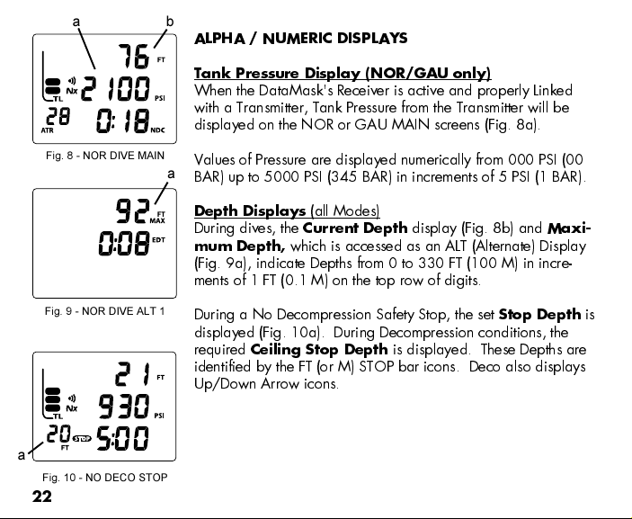
a
Fig. 8 - NOR DIVE MAIN
b
ALPHA / NUMERIC DISPLAYS
Tank Pressure Display (NOR/GAU only)
When the DataMask's Receiver is active and properly Linked
with a Transmitter, Tank Pressure from the Transmitter will be
displayed on the NOR or GAU MAIN screens (Fig. 8a).
Values of Pressure are displayed numerically from 000 PSI (00
a
BAR) up to 5000 PSI (345 BAR) in increments of 5 PSI (1 BAR).
Fig. 9 - NOR DIVE ALT 1
a
Fig. 10 - NO DECO STOP
22
Depth Displays
During dives, the
mum Depth,
(all Modes)
Current Depth
display (Fig. 8b) and
Maxi-
which is accessed as an ALT (Alternate) Display
(Fig. 9a), indicate Depths from 0 to 330 FT (100 M) in incre-
ments of 1 FT (0.1 M) on the top row of digits.
During a No Decompression Safety Stop, the set
Stop Depth
displayed (Fig. 10a). During Decompression conditions, the
required
Ceiling Stop Depth
is displayed. These Depths are
identified by the FT (or M) STOP bar icons. Deco also displays
Up/Down Arrow icons.
is
Page 23
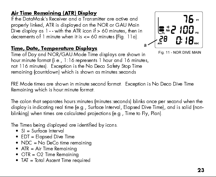
Air Time Remaining (ATR) Display
If the DataMask's Receiver and a Transmitter are active and
properly linked, ATR is displayed on the NOR or GAU Main
Dive display as 1 - - with the ATR icon if > 60 minutes, then in
decrements of 1 minute when it is <= 60 minutes (Fig. 11a).
Time, Date, Temperature Displays
Time of Day and NOR/GAU Mode Time displays are shown in
a
Fig. 11 - NOR DIVE MAIN
hour:minute format (i.e., 1:16 represents 1 hour and 16 minutes,
not 116 minutes). Exception is the No Deco Safety Stop Time
remaining (countdown) which is shown as minutes:seconds
FRE Mode times are shown in minute:second format. Exception is No Deco Dive Time
Remaining which is hour:minute format.
The colon that separates hours:minutes (minutes:seconds) blinks once per second when the
display is indicating real time (e.g., Surface Interval, Elapsed Dive Time), and is solid (non-
blinking) when times are calculated projections (e.g., Time to Fly, Plan).
The Times being displayed are identified by icons.
SI = Surface Interval
EDT = Elapsed Dive Time
NDC = No DeCo time remaining
ATR = Air Time Remaining
OTR = O2 Time Remaining
TAT = Total Ascent Time required
23
Page 24
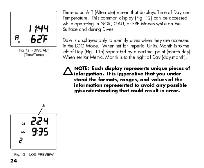
Fig. 12 - DIVE ALT
(Time/Temp)
Fig. 13 - LOG PREVIEW
24
There is an ALT (Alternate) screen that displays Time of Day and
Temperature. This common display (Fig. 12) can be accessed
while operating in NOR, GAU, or FRE Modes while on the
Surface and during Dives.
Date is displayed only to identify dives when they are accessed
in the LOG Mode. When set for Imperial Units, Month is to the
left of Day (Fig. 13a) separated by a decimal point (month.day).
When set for Metric, Month is to the right of Day (day.month).
NOTE: Each display represents unique pieces of
information. It is imperative that you under-
stand the formats, ranges, and values of the
information represented to avoid any possible
misunderstanding that could result in error.
a
Page 25
WARNING: Prior to diving with the DataMask, you must also
read and understand the Oceanic Dive Computer Safety and
Reference Manual, Doc. No. 12-2262, which provides Important
Warnings and Safety Recommendations as well as general
product information.
SURFACE SEQUENCE
AND
OPERATING MODES
25
Page 26

OPERATING MODES
The DataMask features 3 Operating Modes >>
NOR - for Normal Air or Nitrox dives
GAU - for dives with no Nitrogen/Oxygen calculations
FRE - for dives with no SCUBA
Fig. 14A - NOR SURF MAIN
Fig. 14B - GAU SURF MAIN
Fig. 14C - FRE SURF MAIN
26
REMINDER: Once a dive is made in GAU Mode,
the DataMask is locked into that Operating
Mode for 24 hours after the dive.
SURFACE MODE
After activation and while the default Surface Main screen is
displayed, depressing the A (Top) button for 4 sec each time
steps through the operating mode Surface Main screens.
Fig. 14 - NOR MAIN >> GAU MAIN >> FRE MAIN
The Operating Mode selected (NOR, GAU, or FRE) will
remain on display for 2 hours until a dive is made or
another Operating Mode is selected.
If a dive has been conducted within the past 24 hours, the SURF
MAIN screen for that mode will be displayed until changed.
While operating in any Surface Mode, the DataMask will enter
Dive Mode upon descent to 5 FT (1.5 M) for 5 seconds.
Page 27
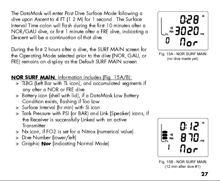
The DataMask will enter Post Dive Surface Mode following a
dive upon Ascent to 4 FT (1.2 M) for 1 second. The Surface
Interval Time colon will flash during the first 10 minutes after a
NOR/GAU dive, or first 1 minute after a FRE dive, indicating a
Descent will be a continuation of that dive.
During the first 2 hours after a dive, the SURF MAIN screen for
the Operating Mode selected prior to the dive (NOR, GAU, or
FRE) remains on display as the Default SURF MAIN screen.
NOR SURF MAIN
, information includes (Fig. 15A/B):
> TLBG (Left Bar with TL icon), and accumulated segments if
any after a NOR or FRE dive.
> Battery icon (shell with lid), if a DataMask Low Battery
Condition exists, flashing if T o o Low.
> Surface Interval (hr:min) with SI icon.
> Tank Pressure with PSI (or BAR) and Link (Speaker) icons, if
the Receiver is successfully Linked with an active
Transmitter.
> Nx icon, if FO2 is set for a Nitrox (numerical value).
> Dive Number (lower/left).
> Graphic
Nor
(indicating Normal Mode).
Fig. 15A - NOR SURF MAIN
(no dive made yet)
Fig. 15B - NOR SURF MAIN
(12 min after dive #1)
27
Page 28
NOR SURF MAIN
Pressing the S (Side) button will turn the Backlight ON/OFF.
Pressing and releasing the A (T op) button repeatedly (< 2 seconds each time) will step
through the NOR Surface Sequence (descriptions start on page 55) -
>> SURF MAIN > SURF ALT1 > SURF ALT2 > PLAN > FLY > SAT > LOG > HISTORY
Depressing S (Side) button repeatedly (2 seconds each time) will step through the SET
Menu screens (descriptions start on page 29) -
>> SURF MAIN > SET G > SET F > SET A > SET U > SET T > SN
Depressing the A (Top) button for 4 seconds will access the GAU SURF MAIN screen
with the graphic GAU flashing, then another 4 second press will access the FRE SURF
MAIN screen with the graphic FRE flashing.
>> NOR SURF MAIN >> GAU SURF MAIN >> FRE SURF MAIN
Pressing and releasing the A (Top) button momentarily (< 2 seconds) while GAU or
FRE is displayed flashing will select that as the Operating Mode which will be
indicated by the graphic becoming solid.
When one Mode graphic in the series is solid, it is the 'selected Operating Mode'.
Ensure it is that Mode that you want and will be diving in.
To activate the DataMask's Receiver and Transmitter Link (for 10 minutes), press and
release the A (Top) button (< 2 seconds). This will cause the ALT1 screen (refer to
page 55) to appear, which will revert to the MAIN screen after 5 seconds.
28
- Button Operations:
Page 29
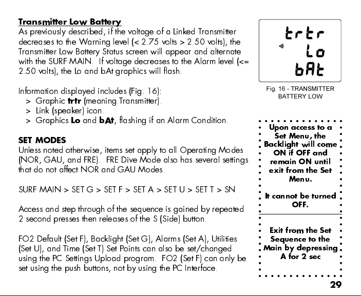
Transmitter Low Battery
As previously described, if the voltage of a Linked Transmitter
decreases to the Warning level (< 2.75 volts > 2.50 volts), the
Transmitter Low Battery Status screen will appear and alternate
with the SURF MAIN. If voltage decreases to the Alarm level (<=
2.50 volts), the Lo and bAt graphics will flash.
Information displayed includes (Fig. 16):
> Graphic
trtr
(meaning Transmitter).
> Link (speaker) icon.
> Graphics Lo and
bAt
, flashing if an Alarm Condition.
SET MODES
Unless noted otherwise, items set apply to all Operating Modes
(NOR, GAU, and FRE). FRE Dive Mode also has several settings
that do not affect NOR and GAU Modes.
SURF MAIN > SET G > SET F > SET A > SET U > SET T > SN
Access and step through of the sequence is gained by repeated
2 second presses then releases of the S (Side) button.
FO2 Default (Set F), Backlight (Set G), Alarms (Set A), Utilities
(Set U), and Time (Set T) Set Points can also be set/changed
using the PC Settings Upload program. FO2 (Set F) can only be
set using the push buttons, not by using the PC Interface.
Fig. 16 - TRANSMITTER
BATTERY LOW
Upon access to a
Set Menu, the
Backlight will come
ON if OFF and
remain ON until
exit from the Set
Menu.
It cannot be turned
OFF.
Exit from the Set
Sequence to the
Main by depressing
A for 2 sec
29
Page 30
GAU and FRE
Operating Modes
are also
described in
separate sections
of this manual.
NOTE: Operation of the S (Side) button while in
a Set Menu will not turn the Backlight OFF as it
does while operating in other modes.
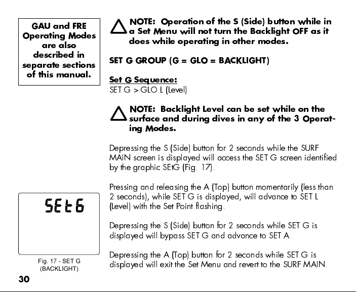
SET G GROUP (G = GLO = BACKLIGHT)
Set G Sequence:
SET G > GLO.L (Level)
NOTE: Backlight Level can be set while on the
surface and during dives in any of the 3 Operat-
ing Modes.
Depressing the S (Side) button for 2 seconds while the SURF
MAIN screen is displayed will access the SET G screen identified
by the graphic SEtG (Fig. 17).
Pressing and releasing the A (Top) button momentarily (less than
2 seconds), while SET G is displayed, will advance to SET L
(Level) with the Set Point flashing.
Depressing the S (Side) button for 2 seconds while SET G is
displayed will bypass SET G and advance to SET A.
30
Fig. 17 - SET G
(BACKLIGHT)
Depressing the A (Top) button for 2 seconds while SET G is
displayed will exit the Set Menu and revert to the SURF MAIN.
Page 31

Set Backlight Level,
information includes (Fig. 18):
Graphic GLO.L
Set Point, flashing
NOTE: GLO Level is the % of the Backlights full
(100%) power of illumination.
While the SET L screen is displayed, pressing and releasing the
S (Side) button momentarily and repeatedly (less than 2 seconds
each time) will step through the Set Points of 5% (Minimum), 25,
50, 75, and 100%, then repeat the step through.
As the Set Point changes, the actual Level of illumination of
the Mask's LCD will change allowing you to determine
which Level setting you prefer.
Pressing and releasing the A (Top) button momentarily (less than
2 seconds) will save the setting and revert back to the SET G
screen.
NOTE: During the first 10 minutes on the surface
following a dive, Backlight Level can be set in
the same manner described above.
Fig. 18 - SET BACKLIGHT
LEVEL
31
Page 32

SET F GROUP (FO2)
Set F Sequence:
SET F > FO2 > FO2 Default.
> Depressing the S (Side) button for 4 seconds while the NOR
Fig. 19 - SET F (FO2)
or GAU SURF MAIN screen is displayed will access SET F
identified by the graphic SEtF (Fig. 19).
> Pressing and releasing the A (Top) button momentarily (< 2
seconds) while SET F is displayed will access the SET FO2
screen with the Set Point flashing.
> Depressing the A (Top) button for 2 seconds while SET F is
displayed will exit the Set Menu and revert to the SURF MAIN.
Setting FO2 for NOR Nitrox Dives:
For each numerical value of FO2 displayed, the MOD (Maximum Operating Depth) that
can be achieved for the PO2 Alarm Set Point limit previously set will be displayed.
NOTE: The MODs will change if the PO2 Alarm Set Point is changed
after setting FO2.
When the FO2 DEFAULT is set ON and FO2 is set for a numerical value, 10 minutes after
surfacing from that dive FO2 will be displayed as 50 (%) and further repetitive dives will
be calculated based on 50% O2 for oxygen calculations and 21% O2 for Nitrogen
calculations (79% Nitrogen), unless FO2 is set to another numerical value before the dive.
32
Page 33

FO2 continues to reset to the FO2 50% DEFAULT after subsequent repetitive dives until 24
hours elapse after the last dive, or the FO2 50% DEFAULT is turned OFF.
When the FO2 50% DEFAULT is set OFF, FO2 for that series of repetitive dives will remain
set at the last FO2 Set Point selected.
The default FO2 for each new dive activation Period is AIR. When FO2 is set for AIR, the
calculations are the same as when it is set for 21%. When FO2 is set to AIR, it remains set
for AIR until it is set for a numerical value (21 to 50%).
When FO2 is set to AIR, the O2 Bar Graph is not displayed at any time during a dive or
on the surface. PO2 values and/or warnings will not be displayed during the dive.
FRE Dive nitrogen calculations are based on AIR and not affected by these FO2 Settings.
Maximum Operating Depths affected by the PO2 limit set will not be displayed when FO2
is set to AIR.
Internally, the DataMask keeps track of the oxygen loading so that if FO2 is subsequently
set for a numerical value, the oxygen loading for previous AIR dives will be accounted for
in the next Nitrox dive (during that dive period and series of repetitive dives).
Once FO2 is set for a numerical value (21 to 50%) and a dive is made, the AIR option is
disabled until 24 hours elapse after the last dive. The AIR option will not be displayed as
Set FO2 option until a full 24 hour Surface Interval has elapsed.
33
Page 34

SET FO2,
information includes:
> Max Depth allowed for the PO2 Alarm Set, if Nitrox
> Nx icon, if Nitrox
> PO2 Alarm Set Point with graphic PO2, if Nitrox
> FO2 Set Point value, flashing
> Graphic FO2
Fig. 20A - SET FO2 = AIR
Fig. 20B - SET FO2 = 32%
34
Depressing and holding the S (Side) button while the Set
Point is flashing will scroll the Set Points from AIR (Fig. 20A)
to 21 through 50% in 1% increments, at a rate of 8 Set
Points per second.
The scroll will stop when the button is released, or
momentarily at 32% (even if the button is held depressed).
Depressing and holding the S (Side) button will resume the
scroll from 32 (Fig. 20B) through 50%, then stop at AIR (or
21%).
Pressing and releasing the S (Side) button (< 2 seconds) will
advance FO2 in increments of 1% per press of the button.
Pressing and releasing the A (Top) button momentarily (< 2
seconds) will save the setting and/or advance to SET FO2
Default with the Set Point flashing.
Pressing and releasing the A (Top) button again (< 2
seconds each) will revert to the SET F screen.
Depressing the A (Top) button for 2 seconds will save the
setting and revert to the SET F screen.
If no button is pressed for 2 minutes, operation will revert to
NOR (or GAU) SURF MAIN screen.
Page 35

SET FO2 50% DEFAULT,
information includes (Fig. 21):
> Graphic dFLt (meaning Default)
> Nx icon
> Set Point graphic ON (or OFF), flashing.
> Graphics 50 and FO2
Pressing and releasing the S (Side) button (< 2 seconds) will
toggle between OFF and ON.
Pressing and releasing the A (Top) button (< 2 seconds) will
save the setting and revert to the SET F screen.
If no button is pressed for a period of 2 minutes, operation
will revert to the NOR (or GAU) SURF MAIN screen.
SET A GROUP (NOR/GAU ALARMS)
Set A Sequence:
SET A > Audible > Depth > EDT > TLBG > DTR > Turn Pressure >
End Pressure > PO2
> The SET A Group items can also be set/changed using the
PC Settings Upload program.
> SET A items do not strike Alarms in FRE Dive Mode.
> SET A Settings remain at the values set until changed.
> Depressing the S (Side) button for 6 seconds while NOR (or
GAU) SURF MAIN is displayed will access SET A identified
by the graphic SEtA (Fig. 22).
Fig. 21 - SET FO2 DEFAULT
FO2 Default can be
set using the push
buttons or the PC
Interface program.
FO2 (%) can only
be set using the
push buttons.
Fig. 22 - SET A (ALARMS)
35
Page 36

> Pressing and releasing the A (Top) button momentarily (< 2 seconds) while SET A is
displayed will advance to SET AUDIBLE ALARM with the Set Point flashing.
> Depressing the A (Top) button for 2 seconds while SET A is displayed will exit the Set
Menu and revert to the SURF MAIN.
SET AUDIBLE ALARM
This option allows the Audible Alarms to be disabled. Some
cautionary situations will cause the Audible Alarm to sound even
if this feature is set to OFF. Setting the Audible OFF will also
prevent it from sounding when FREE Dive Mode Alarms strike.
Fig. 23 - SET AUDIBLE
ALARM
36
SET AUDIBLE ALARM,
information includes (Fig. 23):
> Graphic Aud
> Set Point graphic ON (or OFF), flashing.
Pressing and releasing the S (Side) button (< 2 seconds) will
toggle between ON and OFF.
Pressing and releasing the A (Top) button momentarily (< 2
seconds) will save the setting and/or advance to the SET DEPTH
ALARM screen with the Set Point flashing.
Pressing and releasing the A (Top) button repeatedly (< 2
seconds each) will step through the other SET A screens.
Depressing the A (Top) button for 2 seconds will save the
setting and revert to the SET A screen.
If no button is pressed for 2 minutes, operation will revert to
the NOR (or GAU) SURF MAIN screen.
Page 37

SET DEPTH ALARM,
information includes (Fig. 24):
> FT (or M) and MAX icons
> Set Point Depth value, flashing
> Graphic SdA (meaning Scuba Depth Alarm)
Pressing and releasing the S (Side) button momentarily (< 2
seconds) will step through the Set Points from 30 to 330 FT
(10 to 100 M) in 10 FT (1 M) increments at a rate of 1 Set
Point per press of the button.
Depressing and holding the S (Side) button will scroll
through the Set Points at a rate of 4 Set Points per second
until it is released.
Pressing and releasing the A (Top) button momentarily (< 2
seconds) will save the setting and/or advance to the SET
EDT (Elapsed Dive Time) ALARM screen with the Set Point
flashing.
Pressing and releasing the A (Top) button momentarily and
repeatedly (< 2 seconds each time) will step through the
other SET A screens.
Depressing the A (Top) button for 2 seconds will save the
setting and revert to the SET A screen.
If no button is pressed for a period of 2 minutes, operation
will revert to the NOR (or GAU) SURF MAIN screen.
Fig. 24 - SET DEPTH ALARM
FREE Dive Mode has
separate Depth
Alarms.
37
Page 38

Fig. 25 - Set Depth Alarm
FREE Dive Mode has
a separate (fixed)
EDT Alarm.
38
SET EDT (ELAPSED DIVE TIME) ALARM,
information includes (Fig. 25):
> Graphic Edt (meaning Elapsed Dive Time) and MAX icon
> Set Point value (hr:min), flashing, and EDT icon.
Pressing and releasing the S (Side) button momentarily (< 2
seconds) will increase the Set Point from 0:10 to 3:00
(hours:minutes) in 5 minute (:05) increments.
Depressing the S (Side) button will scroll through the Set
Points at a rate of 4 Set Points per second until it is
released.
Pressing and releasing the A (Top) button momentarily (< 2
seconds) will save the setting and/or advance to the SET
TLBG (Tissue Loading Bar Graph) ALARM screen with the
Set Point flashing.
Pressing and releasing the A (Top) button repeatedly (< 2
seconds each) will step through the other SET A screens.
Depressing the A (Top) button for 2 seconds will save the
setting and revert to the SET A screen.
If no button is pressed for 2 minutes, operation will revert to
the NOR (or GAU) SURF MAIN screen.
Page 39

SET TLBG (TISSUE LOADING BAR GRAPH) ALARM,
information includes (Fig. 26):
> Graphic tLbG (meaning Tissue Loading Bar Graph) and
MAX icon
> TLBG (Left Bar with TL icon) with Set Point (segments),
flashing
Pressing and releasing the S (Side) button momentarily (< 2
seconds) will decrease the Set Point from All 5 segments
(Deco) to 1 in decrements of 1 segment.
Pressing and releasing the A (Top) button momentarily (< 2
seconds) will save the setting and/or advance to the SET
DTR (Dive Time Remaining) ALARM screen with the Set
Point flashing.
Pressing and releasing the A (Top) button repeatedly (< 2
seconds each) will step through the other SET A screens.
Depressing the A (Top) button for 2 seconds will save the
setting and revert to the SET A screen.
If no button is pressed for a period of 2 minutes operation
will revert to the NOR or GAU SURF MAIN screen.
Fig. 26 - SET TLBG ALARM
Setting the TLBG
Alarm to activate
before the
DataMask enters
DECO is highly
recommended.
FREE Dive Mode has
a separate (fixed)
TLBG Alarm.
39
Page 40

SET DTR (DIVE TIME REMAINING) ALARM,
information includes (Fig. 27):
> Graphic dtr (meaning Dive Time Remaining)
> Set Point value (hr:min) flashing.
> OTR, ATR, and NDC icons.
Fig. 27 - SET DTR ALARM
NDC = No Deco Time
ATR = Air Time
OTR = O2 Time
Whichever Time
decreases to the Alarm
Set Point will activate
the Alarm.
40
Pressing and releasing the S (Side) button momentarily (< 2
seconds each time) will increase the Set Point from 0:00 to
0:20 (:minutes) in 1 minute (0:01) increments.
Depressing and holding the S (Side) button will scroll
through the Set Points at a rate of 4 Set Points per second
until it is released.
Pressing and releasing the A (Top) button momentarily (< 2
seconds) will save the setting and/or advance to the SET
TURN PRESSURE ALARM screen with the Set Point flashing.
Pressing and releasing the A (Top) button momentarily and
repeatedly (< 2 seconds each) will step through the other
SET A screens.
Depressing the A (Top) button for 2 seconds will save the
setting and revert to the SET A screen.
If no button is pressed for a period of 2 minutes operation
will revert to the NOR (or GAU) SURF MAIN screen.
Page 41

SET TURN PRESSURE ALARM,
information includes (Fig. 28):
> Graphic turn (TURN)
> Set Point OFF or a numeric value, flashing, and PSI (or BAR)
icon
Pressing and releasing the S (Side) button momentarily (< 2
seconds each time) will step through the Set Points from
OFF then 1000 to 3000 PSI (70 to 205 BAR) in 250 PSI (5
BAR) increments.
Depressing and holding the S (Side) button will scroll
through the Set Points at a rate of 4 Set Points per second
until it is released.
Pressing and releasing the A (Top) button momentarily (< 2
seconds) will save the setting and/or advance to the SET
END PRESSURE ALARM screen with the Set Point flashing.
Pressing and releasing the A (Top) button repeatedly (< 2
seconds each) will step through the other SET A screens.
Depressing the A (Top) button for 2 seconds will save the
setting and revert to the SET A screen.
If no button is pressed for a period of 2 minutes, operation
will revert to the NOR (or GAU) SURF MAIN screen.
Fig. 28 - SET TURN ALARM
Setting the Turn
Pressure Alarm OFF
does not affect the
End Pressure Alarm.
41
Page 42

Fig. 29 - SET END ALARM
End Pressure Alarm
does not have an
OFF Set Point.
42
SET END PRESSURE ALARM,
information includes (Fig. 29):
> Graphic End (END)
> Set Point numeric value, flashing, and PSI (or BAR) icon
Pressing and releasing the S (Side) button momentarily (< 2
seconds each time) will increase the Set Point from 300 to
1500 PSI (20 to 105 BAR) in 100 PSI (5 BAR) increments.
Depressing and holding the S (Side) button will scroll
through the Set Points at a rate of 4 Set Points per second
until it is released.
Pressing and releasing the A (Top) button momentarily (< 2
seconds) will save the setting and/or advance to the SET
PO2 ALARM screen with the Set Point flashing.
Pressing and releasing the A (Top) button repeatedly (< 2
seconds each time) will step through the other SET A
screens.
Depressing the A (Top) button for 2 seconds will save the
setting and revert to the SET A screen.
If no button is pressed for a period of 2 minutes, operation
will revert to the NOR (or GAU) SURF MAIN screen.
Page 43

SET PO2 ALARM,
information includes (Fig. 30):
> Set Point value, flashing, and MAX icon
> Nx icon
> Graphics PO2 and AtA
Pressing and releasing the S (Side) button momentarily (< 2
seconds each time) will increase the Set Point from 1.20
(ATA) to 1.60 (ATA) in .10 (ATA) increments.
Pressing and releasing the A (Top) button momentarily (< 2
seconds) will save the setting and/or revert to the SET A
screen.
If no button is pressed for a period of 2 minutes, operation
will revert to the NOR (or GAU) SURF MAIN screen.
SET U GROUP (UTILITIES)
Fig. 30 - SET PO2 ALARM
Set U Sequence:
SET U > Wet Activation > Units > No Deco Stop > Conservative
Factor > Sampling Rate > Transmitter Link Code
> SET U Settings remain at the values set until changed.
> FRE Mode utilizes these settings for W et Activation and
Units. It has a separate fixed Sampling Rate.
ATA =
Atmospheres
Absolute
43
Page 44

Fig. 31 - SET U (UTILITIES)
Depressing the S (Side) button for 8 seconds while the NOR
(or GAU) SURF MAIN screen is displayed will access SET U
identified by the graphic SEtU (Fig. 31).
> Pressing and releasing the A (Top) button momentarily (< 2
seconds) while SET U is displayed will advance to SET WET
ACTIVATION with the Set Point flashing.
> Depressing the A (Top) button for 2 seconds while SET U is
displayed will exit the Set Menu and revert to the SURF
MAIN.
Fig. 32 - SET WET
ACTIVATION
44
SET WET ACTIVATION,
information includes (Fig. 32):
> Graphics ACt and H2O (meaning W et Activation)
> Set Point graphic ON (or OFF) flashing.
Pressing and releasing the S (Side) button momentarily (< 2
seconds each time) will toggle between ON and OFF.
Pressing and releasing the A (Top) button momentarily (< 2
seconds) will save the setting and/or advance to the SET
UNITS screen with the Set Point flashing.
Pressing and releasing the A (Top) button repeatedly (< 2
seconds each) will step through the other SET U screens.
Depressing the A (Top) button for 2 seconds will save the
setting and revert to the SET U screen.
If no button is pressed for a period of 2 minutes, operation
will revert to the NOR (or GAU) SURF MAIN screen.
Page 45

HINT: To change the Wet Activation setting while operat-
ing in FREE Dive Mode, first access the NOR SURF Mode.
SET UNITS,
information includes (Fig. 33A/B):
> Graphic Unit
> Set Point icons/graphics FT, PSI, and F (or M, BAR, and C),
flashing.
Pressing and releasing the S (Side) button will toggle
between Imperial (FT, PSI, F) and Metric (M, BAR, C).
Pressing and releasing the A (Top) button momentarily (< 2
seconds) will save the setting and/or advance to the SET
NO DECO STOP screen with the Time Set Point flashing.
Pressing and releasing the A (Top) button repeatedly (< 2
seconds each time) will step through the other SET U
screens.
Depressing the A (Top) button for 2 seconds will save the
setting and revert to the SET U screen.
If no button is pressed for a period of 2 minutes, operation
will revert to the NOR (or GAU) SURF MAIN screen.
HINT: To change the Units setting while operating in FREE
Dive Mode, first access the NOR SURF Mode.
Fig. 33A - SET UNITS
(IMPERIAL)
Fig. 33B - SET UNITS
(METRIC)
45
Page 46

SET NOR SAFETY STOP,
information includes (Fig. 34):
> Graphics SAFE and StOP
> Safety Stop Depth Set Point and FT (or M) icon
> STOP Bar icon
> Safety Stop Time Set Point (min:sec), flashing.
Fig. 34 - SET NO DECO
SAFETY STOP
There is no penalty
if you surface before
a No Deco Safety
Stop is completed.
46
Pressing and releasing the S (Side) button momentarily (< 2
seconds each) will step through the Stop Time Set Points of
OFF, 3:00, and 5:00 (min:sec).
Pressing and releasing the A (Top) button momentarily (< 2
seconds) will save the Time setting and the Depth Set Point
will flash, or if Stop Time is set OFF advance to the SET
CONSERVA TIVE FACTOR screen with the Set Point flashing.
Pressing and releasing the S (Side) button momentarily and
repeatedly (< 2 seconds each time) will step through the
Stop Depth Set Points of 10, 15, and 20 FT (or 3, 4, 5,
and 6 M).
Pressing and releasing the A (Top) button momentarily (< 2
seconds) will save the settings and/or advance to the SET
CONSERVA TIVE FACTOR screen with the Set Point flashing.
Pressing the A (Top) button repeatedly (< 2 seconds) will
step through the other SET U screens.
Depressing the A (Top) button for 2 seconds will save the
settings and revert to the SET U screen.
If no button is pressed for a period of 2 minutes, operation
will revert to the NOR (or GAU) SURF MAIN screen.
Page 47

SET CONSERVATIVE FACTOR,
information includes (Fig. 35):
> Graphic CONS (Conservative)
> Set Point ON (or OFF), flashing
> NDC icon
Pressing and releasing the S (Side) button (< 2 seconds each
time) will toggle between ON and OFF.
Pressing and releasing the A (Top) button momentarily (< 2
seconds) will save the setting and/or advance to the SET
SAMPLING RATE screen with the Set Point flashing.
Pressing and releasing the A (Top) button repeatedly (< 2
seconds each time) will step through the other SET U
screens.
Depressing the A (Top) button for 2 seconds will save the
setting and revert to the SET U screen.
If no button is pressed for a period of 2 minutes, operation
will revert to the NOR (or GAU) SURF MAIN screen.
Fig. 35 - SET CONSERVA-
TIVE FACTOR
NOTE: When the Conservative Factor is set ON,
the No Decompression Dive Time Limits are re-
duced to values equivalent to those that would
be available at the next higher 3000 foot (915
meter) Altitude. Refer to the tables in the back
section of the manual.
NDC =
No Deco Dive Time
Remaining
47
Page 48

Fig. 36 - SET SAMPLING
RATE
SAMPLING RATE is
the frequency (time
interval) at which
data is sampled and
stored in memory for
subsequent down-
load to the PC
OceanLog program.
48
SET SAMPLING RATE,
information includes (Fig. 36):
> Graphic Sr (meaning Sampling Rate)
> Set Point (sec), flashing
> Graphic SEC (seconds)
Pressing and releasing the S (Side) button momentarily and
repeatedly (< 2 seconds each time) will step through the Set
Points of 2, 15, 30, 60 (seconds).
Pressing and releasing the A (Top) button momentarily (< 2
seconds) will save the setting and/or advance to the SET
Transmitter Link Code screen with the Set Point flashing.
Pressing and releasing the A (Top) button momentarily and
repeatedly (< 2 seconds each time) will step through the
other SET U screens.
Depressing the A (Top) button for 2 seconds will save the
setting and revert to the SET U screen.
If no button is pressed for a period of 2 minutes, operation
will revert to the NOR (or GAU) SURF MAIN screen.
FREE Dive Mode has a separate fixed Sampling Rate of 1
second.
Page 49

SET TRANSMITTER (trtr) LINK CODE,
information includes
(Fig. 37A/B):
> Graphic trtr (meaning Transmitter)
> Set Point graphic ON (or OFF), flashing
> Link Code Set Point (Transmitter Serial Number)
Pressing and releasing the S (Side) button momentarily (< 2
seconds) will toggle between ON and OFF.
Pressing and releasing the A (Top) button momentarily (< 2
seconds) will accept the ON/OFF selection.
> If OFF is selected, operation will revert to the SET U screen.
> If ON is selected, the First Digit (left) of the Code will flash
(Fig. 37B).
Pressing and releasing the S (Side) button momentarily and
repeatedly (< 2 seconds each time) will increase the First
Digit from 0 to 9 in increments of 1.
Depressing and holding the S (Side) button will scroll
through the Set Points at a rate of 4 per second.
Pressing and releasing the A (Top) button momentarily (< 2
seconds) will accept the First Digit of the Code and/or
advance to the Second Digit which will be flashing.
Pressing and releasing the S (Side) button momentarily and
repeatedly (< 2 seconds each time) will increase the
Second Digit from 0 to 9 in increments of 1.
Depressing and holding the S (Side) button will scroll
through the Set Points at a rate of 4 per second.
Fig. 37A - SET LINK CODE
(ON / OFF)
Fig. 37B - SET LINK CODE
(SERIAL NUMBER)
49
Page 50

Pressing and releasing the A (Top) button momentarily (< 2 seconds) will accept the
Second Digit of the Code and/or advance to the Third Digit which will be flashing.
Pressing and releasing the S (Side) button repeatedly (< 2 seconds each time) will
increase the Third Digit from 0 to 9 in increments of 1.
Depressing and holding the S (Side) button will scroll through the Set Points at a rate
of 4 per second.
Pressing and releasing the A (Top) button (< 2 seconds) will accept the Third Digit of
the Code and/or advance to the Fourth Digit which will be flashing.
Pressing and releasing the S (Side) button repeatedly (< 2 seconds each time) will
increase the Fourth Digit from 0 to 9 in increments of 1.
Depressing and holding the S (Side) button will scroll through the Set Points at a rate
of 4 per second.
Pressing and releasing the A (Top) button momentarily (< 2 seconds) will accept the
Fourth Digit of the Code and/or advance to the Fifth Digit which will be flashing.
Pressing and releasing the S (Side) button repeatedly (< 2 seconds each time) will
increase the Fifth Digit from 0 to 9 in increments of 1.
Depressing and holding the S (Side) button will scroll through the Set Points at a rate
of 4 per second.
Pressing and releasing the A (Top) button momentarily (< 2 seconds) will accept the
Fifth Digit of the Code, save the setting, and revert to the SET U screen.
If no button is pressed for a period of 2 minutes, operation will revert to the NOR (or
GAU) SURF MAIN screen.
50
Page 51

SET T GROUP (TIME/DATE)
Set T Sequence:
SET T > Hour Format > Hour > Minute > Year > Month > Day
> The SET T Group can also be set/changed using the PC
Settings Upload program.
> SET T Settings remain at the values set until changed.
> FREE Dive Mode utilizes these settings.
> Day of the Week is set automatically when the Date is set.
Depressing the S (Side) button for 10 seconds while the
NOR (or GAU) SURF MAIN screen is displayed will access
SET T identified by the graphic SEtt (Fig. 38).
Pressing and releasing the A (Top) button momentarily (< 2
seconds) while SET T is displayed will advance to SET
HOUR FORMAT with the Set Point flashing.
Depressing the A (Top) button for 2 seconds while SET T is
displayed will exit the Set Menu and revert to the SURF
MAIN.
Fig. 38 - SET T (TIME /
DATE)
SET HOUR FORMAT,
information includes (Fig. 39):
> Graphic Hour
> Set Point 12 (or 24), flashing.
Fig. 39 - SET HOUR
FORMAT
51
Page 52

Pressing and releasing the S (Side) button momentarily (< 2 seconds) will toggle
between 12 and 24.
Pressing and releasing the A (Top) button momentarily (< 2 seconds) will save the
Hour Format Set Point and access the SET TIME screen with the HOUR Set Point
flashing.
Depressing and holding the A (Top) button for 2 seconds will save the setting and
revert to the SET T screen.
If no button is pressed for a period of 2 minutes, operation will revert to the NOR (or
GAU) SURF MAIN screen.
SET TIME
(Hour and Minute)
The graphic Am or Pm will be displayed when 12 Hour Format has been selected.
Depressing and holding the S (Side) button while the HOUR Set Point is flashing (Fig.
40) will scroll through the Set Points in 1 Hour increments at a rate of 4 per second
from 12: Am to 11: Pm (or 0: to 23: if set for 24 Hour Format).
Pressing and releasing the A (Top) button momentarily (< 2
seconds) will save the Hour Set Point and/or advance to SET
MINUTE with the MINUTE Set Point flashing.
Depressing and holding the S (Side) button while the MINUTE
Set Point is flashing will scroll through the Set Points in 1 minute
increments at a rate of 4 per second from :00 to :59.
Pressing and releasing the A (Top) button momentarily (< 2
seconds) will save the Minute Set Point and/or advance to the
SET DATE screen with the YEAR Set Point flashing.
Fig. 40 - SET TIME
52
Page 53

Depressing and holding the A (Top) button for 2 seconds
will save the setting and revert to the SET T screen.
If no button is pressed for a period of 2 minutes, operation
will revert to the NOR (or GAU) SURF MAIN screen.
SET DATE
Displayed numerically will be the Month and Day (or Day and
Month if set for metric) and the YEAR Set Point flashing (Fig. 41).
(Year, Month, and Day)
Fig. 41 - SET DATE
Depressing and holding the S (Side) button will scroll
through the YEAR Set Points in 1 year increments at a rate of 4 per second from
2007 to 2050 (with leap year corrections).
Pressing and releasing the A (Top) button momentarily (< 2 seconds) will save the
YEAR Set Point and/or advance to SET MONTH with the Set Point flashing.
Depressing and holding the S (Side) button will scroll through the MONTH Set Points
in 1 month increments at a rate of 4 per second from 1 to 12.
Pressing and releasing the A (Top) button momentarily (< 2 seconds) will save the
Month Set Point and/or advance to SET DAY with the Set Point flashing.
Depressing and holding the S (Side) button will scroll through the DAY Set Points in
one day increments at a rate of 4 per second from 1 to 31.
Pressing and releasing the A (Top) button momentarily (< 2 seconds) will save the
Time/Date Set Points and revert to the SET T screen.
If no button is pressed for a period of 2 minutes, operation will revert to the NOR (or
GAU) SURF MAIN screen.
53
Page 54

SERIAL NUMBER
(DataMask) - view only
Depressing and holding the S (Side) button for 12 seconds
while viewing the NOR (or GAU) SURF MAIN screen will
access the Mask's SERIAL NUMBER screen, displaying (Fig.
42):
Fig. 42 - SERIAL NUMBER
NOR (or GAU)
SURF MAIN >>
SET G >>
SET F >>
SET A >>
SET U >>
SET U >>
SN
54
> Firmware revision number (e.g., graphic r1A)
> Graphic SN (meaning Serial Number)
> Factory programmed Serial Number of the DataMask
Depressing and holding the S (Side) button for 2 seconds
will revert to the SURF (or GAU) SURF MAIN screen.
If no button is pressed during a period of 2 minutes,
operation will revert to the NOR (or GAU) SURF MAIN
screen.
Depressing the A (Top) button for 2 seconds will revert to
the SURF MAIN.
NOTE: The Serial Number and Firmware Revi-
sion will be requested in the event that you
contact Oceanic regarding your DataMask.
Enter them in the Records section provided in the
back of this Manual.
Page 55

SURF ALT 1
, information includes (Fig. 43):
This screen can only be accessed after a NOR Nitrox dive and
is bypassed after NOR Air dives.
Pressing and releasing the A (Top) button momentarily (< 2
seconds) while viewing the NOR SURF MAIN screen will
access the SURF ALT 1 screen, displaying (Fig. 50):
> O2BG (Right Bar with O2 icon) and accumulated segments
> Nx icon
> FO2 Set Point with graphic FO2
Pressing and releasing the A (Top) button momentarily (< 2
seconds) will access the SURF ALT 2 screen.
Depressing the S (Side) button will toggle the Backlight.
The display will revert to the NOR SURF MAIN screen after
5 seconds of no button action.
Fig. 43 - SURF ALT 1
SURF ALT 2
, information includes (Fig. 44):
> Altitude as graphic EL - 2 to EL - 7, when > 3,000 feet
> Time of Day (hr:min), with graphic Am (or Pm) when set for
12 Hour Format
> Temperature with degree icon and graphic F (or C)
Fig. 44 - SURF ALT 2
55
Page 56

After NOR Air dives, pressing and releasing the A (Top) button momentarily (< 2
seconds) while viewing the NOR SURF MAIN screen will access the SURF ALT 2
screen (the SURF ALT 1 screen would not be available).
After NOR Nitrox dives, pressing and releasing the A (Top) button 2 times
momentarily (< 2 seconds each time) while viewing the NOR SURF MAIN screen will
access the SURF ALT 2 screen.
Pressing and releasing the A (Top) button momentarily (< 2 seconds) will then access
the NOR PLAN Lead-in screen.
Pressing the S (Side) button will toggle the Backlight.
The display will revert to the NOR SURF MAIN after 5 seconds of no button action.
NOR PLAN MODE
Oceanic strongly recommends that you review the Pre Dive Planning Se-
quence (PDPS) prior to every NOR dive to help you Plan your dive as
required to avoid exceeding no decompression or oxygen exposure limits.
This is especially important for repetitive dives when the PDPS indicates adjusted dive times
that are available for the next dive, based on residual nitrogen or oxygen accumulation
(whichever is in control) following the last dive and surface interval.
NOTE: No Decompression Dive Time Limits in NOR PLAN MODE are
based on the FO2 Set Point.
Pressing and releasing the A (Top) button momentarily (< 2 seconds) while the SURF
ALT 2 screen is displayed will access the PLAN MODE Lead-in screen (NOR SURF >
PLAN Lead-in).
56
Page 57

While in the PLAN MODE, pressing and releasing the S (Side) button repeatedly (< 2
seconds each time) will increase the Planned Depth in increments of 10 FT (3 M),
displaying the information one screen at a time.
Information provided includes Depths and allowable No Decompression Dive Times. The
screens will sequence through Depths from 30 to 190 FT (9 to 57 M), or the Maximum
Depth that will allow theoretical No Decompression Dive Time of at least 1 minute based
upon the previous dive profiles in a series of repetitive dives and taking into account
descent and ascent rates of 60 FPM (18 MPM).
NOTE: When the Conservative Factor is set ON, No Decompression
Dive times are reduced to the values of the next 3000 foot (915
meter) higher Altitude. See tables in the Reference section.
If FO2 is set for a numerical value (21 to 50%), the Nx (Nitrox) icon and Maximum
Operating Depth defined by the PO2 ALARM Set Point will be displayed.
If the limiting time factor is Nitrogen controlled, the symbols TIME and NDC will be dis-
played. If the limiting time factor is Oxygen controlled, the symbols TIME and O2 will be
displayed.
Prior to a first dive of a series, pressing and releasing the A (Top) button momentarily
(< 2 seconds) will advance to LOG MODE.
After a dive is made, it will advance to FLY MODE.
If no button is pressed during a 2 minute period, operation will revert to the NOR
SURF MAIN screen.
57
Page 58

PLAN MODE LEAD-IN,
information includes (Fig. 45A/B):
> Graphic PLAN
> Nx icon, if set for Nitrox
> PO2 Alarm Set Point, if set for Nitrox.
> FO2 Set Point and graphic FO2, if Nitrox; or graphic Air
Fig. 45A - PLAN (FO2 = AIR)
Fig. 45B - PLAN (FO2 = 32)
Fig. 46 - PDPS
58
Press and release the S (Side) button momentarily (< 2
seconds) to access the first Depth/Time screen (30 FT/9 M)
of the Pre Dive Planning Sequence (PDPS).
PDPS,
information includes (Fig. 46):
> TLBG (Left Bar with TL icon) with 4 segments if calculations
are controlled by Nitrogen, or -
> O2BG (Right Bar with O2 icon) with 4 segments if
calculations are controlled by Oxygen
> Nx icon, if FO2 is set Nitrox
> PO2 Alarm Set Point, if FO2 is set for Nitrox
> Plan Depth values with F (feet) or M (meters) icon
> Dive Time allowed (hr:min) for the FO2 set with NDC icon if
Nitrogen controlled, or OTR icon if Oxygen controlled
> Maximum Depth allowed for the PO2 Alarm value set with
FT (or M) and MAX icons
Page 59

Press and release the S (Side) button momentarily and repeatedly (< 2 seconds each
time) to step through the Planned Depths in increments of 10 FT (3 M), displaying the
information one screen at a time, then reverting to the NOR SURF MAIN screen.
NOTE: While operating in the PDPS, presses of the S (Side) button will
not toggle the Backlight.
FLY MODE
Time to Fly is a counter that begins counting down 10 minutes after surfacing from a dive
from 23:50 to 0:00 (hr:min).
Two hours after a NOR or FRE dive, the FLY screen will alternate with the SAT screen until
the DataMask shuts Off 24 hours after the last dive. When operating in FREE Dive Mode,
the FLY screen can be viewed by first accessing the NOR SURF MAIN screen.
During the first 2 hours after a dive -
while the NOR SURF MAIN screen is displayed after an AIR or FREE dive, pressing
and releasing the A (Top) button 3 times momentarily (< 2 seconds each time) will
access the FLY screen (SURF MAIN > ALT 2 > PLAN > FL Y), or -
after a Nitrox dive, pressing and releasing the A (Top) button 4 times will access the
FLY screen (SURF MAIN > ALT 1 > ALT 2 > PLAN > FLY).
59
Page 60

TIME TO FLY,
information includes (Fig. 47):
> Graphic FLY
> Countdown Time (hr:min).
> Battery icon (shell with lid), if a DataMask Low Battery
Condition exists, flashing if T o o Low.
Fig. 47 - time to fly
Pressing and releasing the A (Top) button momentarily (< 2
seconds) will access the SAT screen.
The display will revert to the NOR SURF MAIN screen after 2
minutes of no button action.
Pressing the S (Side) button will toggle the Backlight.
SAT MODE
The Time to Desaturate counter provides calculated time for Tissue Desatuation at sea level
taking into consideration the Conservation Factor setting. It begins counting down 10
minutes after surfacing from a dive, counting down from 23:50 max to 0:00 (hr:min).
When the Countdown reaches 0:00, which will generally occur prior to the FLY count-
down reaching 0:00, the SAT screen continues to alternate with FLY displaying 0:00 until
the FLY counter shuts the DataMask Off 24 hours after a last dive.
> The SAT screen is not displayed after a V iolation Dive.
> Desaturation requiring Times greater than 24 hours will display 23: - - .
> In the event that Time to Desaturate still remains at the end of 24 hours, the added
time will be zeroed.
60
Page 61

During the first 2 hours after a dive -
while the NOR SURF MAIN screen is displayed after an AIR or FRE dive, pressing
and releasing the A (Top) button 4 times (< 2 seconds each time) will access the SAT
screen (SURF MAIN > ALT 2 > PLAN > FLY > SAT), or -
after a NOR Nitrox dive, pressing and releasing the A (Top) button 5 times will access
the SAT screen (SURF MAIN > ALT 1 > ALT 2 > PLAN > FLY > SAT).
Two hours after a NOR or FRE dive, the SAT screen will alternate with the FLY screen until
the DataMask shuts Off 24 hours after the last dive. When operating in FREE Dive Mode,
the SAT screen can be viewed by first accessing the NOR SURF MAIN screen.
TIME TO DESAT,
information includes (Fig. 48):
> Graphic SAt
> Countdown Time (hr:min).
> Battery icon (shell with lid), if a Low Battery Warning
Condition exists, flashing if T o o Low.
Pressing and releasing the A (Top) button momentarily (< 2
seconds) will access the LOG Preview screen.
The display will revert to the NOR SURF MAIN screen after
2 minutes of no button action.
Pressing the S (Side) button will toggle the Backlight.
Fig. 48 - DESATURATION
TIME
61
Page 62

NOR/GAU LOG MODE
LOG MODE displays information from the latest 24 NOR/GAU dives sequentially in
reverse order (the most recent first).
Dives will be numbered 1 to 24 starting at #1 each time a new series of dives begins.
After it shuts Off 24 hours after a dive, the first dive of the next new series will be #1.
LOG information is retained until deleted by another dive.
> After exceeding 24 dives, the most recent Dive completed will be added to the LOG
and the oldest deleted.
Battery removal will not affect the data stored in the LOG for viewing.
Accessing LOG Mode:
Access to Log Mode is dependent upon diving activity previously conducted.
While operating in Log Mode, presses of the S (Side) button will not toggle the Backlight.
During the first 10 minutes after a dive, pressing and releasing the A (Top) button
momentarily (< 2 seconds) while the NOR SURF MAIN screen is displayed will
access LOG MODE. (SURF MAIN > LOG)
10 minutes after a Non Violation Nitrox Dive, pressing and releasing the A (Top)
button 6 times (< 2 seconds each time) while the NOR SURF MAIN screen is
displayed will access LOG MODE (SURF MAIN > ALT 1 > ALT 2 > PLAN > FL Y > SAT
> LOG).
62
Page 63

10 minutes after a Non Violation AIR Dive, pressing and releasing the A (Top) button
5 times (< 2 seconds each time) while the NOR SURF MAIN screen is displayed will
access LOG MODE (SURF MAIN > ALT 2 > PLAN > FLY > SA T > LOG).
10 minutes after a GAU or Violation Dive, pressing and releasing the A (Top) button
3 times (< 2 seconds each time) while the NOR (or GAU) SURF MAIN screen is
displayed will access LOG MODE (SURF MAIN > ALT 2 > FLY > LOG).
ALT 1, PLAN, and SAT screens will not be available after a Violation (or GAU) Dive.
Upon accessing LOG MODE, the most recent NOR (or GAU) dives LOG PREVIEW screen
will be displayed.
Depressing and holding the S (Side) button for 2 seconds will display the previous
dives PREVIEW screen. Subsequent 2 second presses/releases of the S (Side) button
will step through other previous dives' PREVIEW screens.
Pressing and releasing the S (Side) button momentarily (< 2 seconds) while viewing a
PREVIEW screen will display that dives DATA 1 screen.
Pressing and releasing the S (Side) button momentarily (< 2 seconds) while viewing
the DATA 1 screen will display that dives DAT A 2 screen.
If that was a Nitrox dive, pressing and releasing the S (Side) button momentarily (< 2
seconds) while viewing the DATA 2 screen will display that dives DATA 3 screen.
LOG screens remain on display until further button action occurs.
Once the S (Side) button is pressed, pressing and releasing the A (Top) button
momentarily (< 2 seconds) will revert to the NOR (or GAU) SURF MAIN screen.
If no button is pressed during a 2 minute period, operation will revert to the NOR (or
GAU) SURF MAIN screen.
63
Page 64

Fig. 49 - LOG PREVIEW
LOG PREVIEW,
information includes (Fig. 49):
> Log Mode icon
> Date (month.day, or day.month if set for metric)
> Nx icon, if a Nitrox dive
> Time of Day the dive began (hr:min)
> Dive number (1 to 24) for that series (at lower/left)
Pressing and releasing the S (Side) button momentarily (< 2
seconds) button will advance to the DATA 1 screen.
Pressing and holding the S (Side) button will scroll through
the previous Log Preview screens.
If no button is pressed during a 2 minute period, operation
will revert to the NOR (or GAU) SURF MAIN screen.
Fig. 50 - LOG DATA 1
64
LOG DATA 1,
information includes (Fig. 50):
> Log Mode icon
> Surface Interval (prior to the dive) with SI icon
> Nx icon, if a Nitrox dive
> Graphic No-d (indicating No Decompression), or dECO
(Decompression), or GAU (Gauge), or VIOL (Violation)
identifying the type of dive
> Dive number (1 to 24) for that series (at lower/left)
> T emperature (minimum recorded that dive) with degrees
icon and graphic F (or C)
Page 65

Pressing and releasing the S (Side) button momentarily (< 2
seconds) button will advance to the LOG DATA 2 screen.
If no button is pressed during a 2 minute period, operation
will revert to the NOR (or GAU) SURF MAIN screen.
LOG DATA 2,
information includes (Fig. 51):
> TLBG (left bar and TL icon) with the maximum accumulation
segment flashing, others fixed up to end of dive
accumulation. All segments flashing if a Delayed Violation
# 1 or 2 or Full Violation occurred.
> Log Mode icon
> Maximum Depth and FT (or M) and MAX icons
> Elapsed Dive Tine (hr:min) with EDT icon
Pressing and releasing the S (Side) button momentarily (< 2
seconds) button will advance to the DATA 3 screen.
If no button is pressed during a 2 minute period, operation
will revert to the NOR (or GAU) SURF MAIN screen.
LOG DATA 3,
(if a Nitrox dive) information includes (Fig. 52):
> O2BG (right bar and O2 icon) with the segments
representing Oxygen accumulated at the end of the dive.
> Log Mode icon
> Nx icon
> Maximum level of PO2 reached (ATA) and graphic PO2
> FO2 Set Point for the dive with graphic FO2
Fig. 51 - LOG DATA 2
Fig. 52 - LOG DATA 3
65
Page 66

Pressing and releasing the S (Side) button momentarily (< 2 seconds) will advance to
the previous dive's LOG PREVIEW screen. After viewing the last dive in the Log,
operation will revert to the NOR (or GAU) SURF MAIN screen.
If no button is pressed during a 2 minute period, operation will revert to the NOR (or
GAU) SURF MAIN screen.
FREE Dives are not recorded in the LOG or HISTORY. The data is stored in Memory
for subsequent Download to the Oceanlog PC Interface program.
NOR/GAU HISTORY MODE
HISTORY Mode displays accumulated NOR and GAU dive information.
10 minutes after a NOR Nitrox dive -
pressing and releasing the A (Top) button 7 times momentarily (< 2 seconds each
time) while the NOR (or GAU) SURF MAIN screen is displayed will access History
Mode displaying the HISTORY 1 screen -
(SURF MAIN > ALT 1 > ALT 2 > PLAN > FL Y > SAT > LOG > HISTORY).
10 minutes after a NOR AIR dive -
pressing and releasing the A (Top) button 6 times momentarily (< 2 seconds each
time) while the NOR (or GAU) SURF MAIN screen is displayed will access HISTORY
1 - (SURF MAIN > ALT 2 > PLAN > FLY > SAT > LOG > HISTORY).
10 minutes after a GAU dive -
pressing and releasing the A (Top) button 4 times momentarily (< 2 seconds each
time) while the GAU SURF MAIN screen is displayed will access HISTORY 1 -
(SURF MAIN > ALT 2 > FLY > LOG > HISTORY).
66
Page 67

While operating in History Mode, presses of the S (Side) button
will not toggle the Backlight.
HISTORY 1,
information includes (Fig. 53):
> Graphic HiSt
> Total Hours of Elapsed Dive Time up to 9999 with EDT icon
> Total number of All NOR (and GAU) dives recorded up to
999 with No icon (No meaning Number)
Pressing and releasing the S (Side) button momentarily (< 2
seconds) button will advance to the HISTORY 2 screen.
If no button is pressed during a 2 minute period, operation
will revert to the NOR (or GAU) SURF MAIN screen.
HISTORY 2,
information includes (Fig. 54):
> Maximum Depth achieved during any NOR (or GAU) dive
with FT (or M) and MAX icons
> Graphic EL - 2 to EL - 7, indicating the highest Altitude (>
3,000 feet) at which a NOR (or GAU) dive was conducted.
(EL meaning elevation). No indication means SEA Level.
> Temperature with degrees icon and graphic F (or C), lowest
ever recorded during any NOR (or GAU) dive
Pressing and releasing the S (Side) button momentarily (< 2
seconds) button will advance to the NOR (or GAU) SURF
MAIN screen.
Fig. 53 - HISTORY 1
Fig. 54 - HISTORY 2
67
Page 68

68
WARNING: If your DataMask stops working for any reason
while operating as a Dive Computer, it is important that you
have anticipated this possibility and are prepared for it. This
is an important reason for not pushing the no decompression
and oxygen exposure limits, and a critical reason to avoid
entering decompression. If you dive in situations where your
trip would be ruined or your safety would be jeopardized by
losing the use of your DataMask, a backup instrument sys-
tem is highly recommended.
Page 69

WARNING: Prior to diving with the DataMask, you must also
read and understand the Oceanic Dive Computer Safety and
Reference Manual, Doc. No. 12-2262, which provides Important
Warnings and Safety Recommendations as well as general
product information.
OVERVIEW OF DIVE MODE
INFORMA TION
69
Page 70

Fig. 55 - TRANSMITTER
POSITIONING
70
POSITIONING A TRANSMITTER AND MASK
When installing a Transmitter on a Regulator First Stage (Fig.
55), it is important that it be properly positioned for actual use
with the Mask.
The Transmitter is a Battery powered electronic device that
contains a Pressure Transducer designed to measure Pressure of
a Tank that it is fitted to. It also contains a microcomputer that
converts data from the Pressure Sensor and emits Radio Fre-
quency data signals capable of being received by the electron-
ics of the Mask.
The Transmitter emits a low frequency signal that radiates
outward in a semicircular pattern that is parallel to its length
dimension. A coiled antenna inside the Mask receives the signal
when it is positioned within range of the Transmitter.
Once it is activated by sensing a Pressure of 120 PSI (8.4 BAR),
or greater, it will transmit a signal of sufficient strength to be
received by the Mask at distances up to 3 feet (1 meter).
Link Interruption Underwater
During operation, the Mask (receiving unit) may be moved out of
the signal pattern of the Transmitter, resulting in a temporary
interruption of the transmitted Link signal.
Page 71

An interruption lasting greater than 15 seconds will cause the
Tank Pressure value and the Link (Signal) icon to flash on the
Mask's display (Fig. 56). An interruption of the Link may also
occur while operating -
within 3 feet (1 meter) of a running Dive Propulsion Vehicle.
when using a Strobe (a temporary interruption may occur
shortly after the Strobe flashes).
within 6 feet (2 meters) of a PC CRT monitor, in which case
the Mask and Transmitter may have to be moved to within
inches of each other to maintain the Link.
The Link will be restored within 4 seconds after the above
conditions are corrected.
DIVE TIME REMAINING (DTR)
One of the most important pieces of information on Oceanic
dive computers is the Dive Time Remaining numeric display. The
DataMask constantly monitors No Decompression status, Oxy-
gen Accumulation, and Air Consumption Rate.
The Dive Time Remaining display (Fig. 57a) will indicate the No
Deco (NDC), O2 (OTR), or Air Time (ATR) Remaining, whichever
Time is the least amount available. The specific Time being
displayed is identified by the NDC or OTR or ATR icons.
Fig. 56 - LOSS OF LINK
a
Fig. 57 - DIVE TIME
REMAINING
71
Page 72

Fig. 58 - ATR ALARM
(during No Deco)
Fig. 59 - ATR ALARM
(during other conditions)
72
ATR will be displayed on the Main display (lower/left) when it is
60 minutes or less in decrements of 1 minute).
In the event that ATR becomes less than 5 minutes during No
Deco conditions, the Audible Alarm will sound, and the ATR
value will flash (Fig. 58) until it is > 5 minutes.
During other conditions, the Audible Alarm will sound, and the
graphic ATR will flash in place of Dive Time Remaining (Fig. 59).
The value of ATR can be viewed by pressing and releasing the A
(Top) button (< 2 seconds) to access the ALT 1 screen
No Decompression Dive Time Remaining (NDC)
No Decompression Dive Time Remaining is the maximum
amount of time that you can stay at your present Depth before
entering a Decompression situation. It is calculated based on
the amount of Nitrogen absorbed by hypothetical tissue compart-
ments. The rates each of these compartments absorb and
release Nitrogen is mathematically modeled and compared
against a maximum allowable Nitrogen level.
Whichever one is closest to this maximum level is the controlling
compartment for that Depth. Its resulting value will be displayed
numerically along with the NDC icon and graphically as the
Tissue Loading Bar Graph.
Page 73

As you ascend from Depth following a dive that has approached
the No Decompression Limit, the TLBG segments will recede (Fig.
60a) as control shifts to slower compartments. This is a feature
of the Decompression Model that is the basis for Multilevel
Diving, one of the most important advantages that Oceanic dive
computers offer.
The DataMask's algorithm is based upon Haldanes theory using
maximum allowable nitrogen levels developed by Merrill Spen-
cer. Repetitive diving control is based upon experiments de-
signed and conducted by Dr. Ray Rogers and Dr. Michael
Powell in 1987. Diving Science and Technology® (DSAT), a
corporate affiliate of PADI®, commissioned these experiments.
Oxygen Accumulation Time Remaining (OTR)
When the DataMask is set for Nitrox operation, Oxygen Accu-
mulation (saturation or exposure) during a dive, or 24 hour
period, appears graphically as the O2 Bar Graph (O2BG) (Fig.
61a). As time remaining before reaching the Oxygen Exposure
Limit decreases, segments are added to the O2BG.
When the amount of time remaining before reaching the Oxy-
gen Limit (OTR) becomes less than the No Decompression Dive
Time Remaining (NDC), calculations for that Depth will be
controlled by Oxygen.
a
Fig. 60 - TLBG
a
Fig. 61 - O2BG
73
Page 74

Oxygen Time Remaining (OTR) will then appear as the Dive Time
Remaining (DTR) display (Fig. 62a) as signified by the OTR icon
replacing the NDC icon. As Oxygen Accumulation continues to
increase, segments will add to the O2BG.
Fig. 62 - OTR is DTR
a
Air Time Remaining (ATR)
The DataMask calculates Air Time Remaining (ATR) using a patented Algorithm that is
based on a diver's individual Air Consumption Rate and Current Depth.
> T ank Pressure is measured once each second and an average rate of Consumption is
calculated over a 90 second period.
> This Rate of Consumption is then used in conjunction with a knowledge of the Depth
dependence to predict the Air required for the diver to make a safe controlled Ascent
including a No Deco Safety Stop (if set) and/or any required Decompression Stops.
Air Consumption and Depth are continuously monitored and Air Time Remaining reflects
any change in circumstances. For example, when find yourself swimming against a strong
current and begin breathing more rapidly, the DataMask will recognize the change and
adjust the ATR accordingly.
ATR is the time you can remain at your present Depth and still surface with the Tank
Pressure Reserve that you selected during setup (End Pressure Alarm Setting).
74
Page 75

ATR, identified by the ATR icon, is displayed digitally at the
lower/left of the MAIN Dive screen (Fig. 63a).
In the event that ATR becomes less than NDC and O2 Time, it
will be displayed on the Main Display as Dive Time Remaining
(DTR) until it becomes greater than one or the other.
a
Air Time Remaining (ATR) Alarm
When ATR decreases to 5 minutes (0:05), the Audible Alarm will
sound and the ATR value (lower/left) will flash.
If ATR decreases to 0:00, the Audible will sound again. The
message
Atr
will flash in place of DTR (Fig. 64) until ATR
becomes greater than 5 minutes (0:05).
You should immediately initiate a controlled Ascent while moni-
toring your Tank Pressure. However, there is no reason to
panic, the DataMask has allowed for the Air necessary for a
safe Ascent including the No Deco Safety Stop, if set On, and
any Decompression Stops required. Example:
You set the End Pressure Alarm for 300 PSI (20 BAR)
You are at a Depth of 60 FT (20 M)
Air Time Remaining decreases to 0:00
You Ascend at a maximum rate of 30 FPM (10 MPM)
You surface with 300 PSI (20 BAR) pressure still in your
Tank.
Fig. 63 - MAIN DIVE
DISPLAY
Fig. 64 - ATR ALARM
75
Page 76

ASCENT RATE ALARM
Alarms associated with Ascent Rate are based upon 2 sets of
speeds which change at a reference depth of 60 FT (18 M).
Fig. 65 - ASCENT RATE
ALARM
Fig. 66A - TURN PRESSURE
ALARM
Fig. 66B - END PRESSURE
ALARM
76
The Audible will sound and the graphic
SLO
will flash in place
of DTR (Fig. 65). The Audible will stop when acknowledged by
pressing and releasing the A (Top) button, or after 10 seconds,
or when the Ascent is slowed. The graphic will continue to flash
until Ascent is slowed, then DTR (hr:min) will reappear.
WARNING: At depths greater than 60 FT (18 M),
Ascent Rates should not exceed 60 FPM (18
MPM). At depths of 60 FT (18 M) and shallower,
Rates should not exceed 30 FPM (9 MPM).
TANK PRESSURE ALARMS
Alarms associated with Pressure are set prior to dives utilizing
the NOR/GAU Set A menu selections.
The Audible will sound and the graphic
trn
then
End
will flash
in place of DTR (Fig. 66A/B). The Audible will stop when
acknowledged by pressing and releasing the A (Top) button, or
after 10 seconds. The graphic(s) will flash for 10 seconds, then
DTR (hr:min) will reappear.
Page 77

CONTROL OF DISPLAYS
During Dive Modes, there is a Main (Default) Display of important information relevant to
the specific mode that the DataMask is operating in (No Deco, Deco, GAU, FRE, etc.).
Alternate (ALT) Displays can be accessed by pressing and releasing the A (Top) button to
view additional information. They will automatically revert to the Main Display after 5
seconds unless the A (Top) button is pressed again to view another Alternate Display.
DIVE MAIN > ALT 1 > ALT 2 (only if Nitrox) > ALT 3
Alarms can be acknowledged/silenced by pressing the A (Top) button for 2 seconds.
The S (Side) button is used to toggle the Backlight On/Off.
When Alarms strike, the Backlight will come On if set Off and remain On until the
Alarm condition clears.
The Backlight will not activate during a Low Battery condition.
WET CONTACTS
The Wet Contact Dive Mode Activation feature is active when it is set ON. The DataMask
is configured with contacts that will automatically activate Dive Mode when the space
between the contacts is bridged by a conductive material (immersed in water) and it
senses a Depth of 5 FT (1.5 M) for 5 seconds.
When the Wet Activation feature is set OFF, the DataMask will not enter Dive Mode upon
descent unless it is first Activated by push button and operating in one of the Dive Com-
puter modes (menus) at that time, a mode such as Surface, Fly, Log, etc.
77
Page 78

78
(This page intentionally left blank.)
Page 79

WARNING: Prior to diving with the DataMask, you must also
read and understand the Oceanic Dive Computer Safety and
Reference Manual, Doc. No. 12-2262, which provides Important
Warnings and Safety Recommendations as well as general
product information.
NOR TYPE DIVE MODES
79
Page 80

Fig. 67 - NOR DIVE MAIN
NOR DIVE MAIN
(Default), information includes (Fig. 67) -
> TLBG (Left Border with TL icon), segments representing
Nitrogen Loading
> Current Depth with FT (or M) icon
> Tank Pressure with the PSI (or BAR) and Link icons, if a TRTR
is active and linked, flashing after 1 minute of Lost Link
> Nx icon, if a Nitrox dive
> ATR (decrements of 1 min), if =< 60 min. If ATR is
displayed as DTR, it will not be displayed at the lower/left.
> DTR (hr:min) with NDC (or OTR or ATR) icon
Press/release the A (Top) button (< 2 seconds) to view the
NOR DIVE ALT 1 screen.
Fig. 68 - NOR DIVE ALT 1
80
NOR DIVE ALT 1,
information includes (Fig. 68)
> Max Depth with FT (or M) and MAX icons
> Elapsed Dive Time (hr:min) with EDT icon
> If ATR is displayed on the Main screen as DTR, NDC or
OTR (whichever is less) will be displayed with the TLBG or
O2BG.
The display will revert to the MAIN Display after 5 seconds
unless A is pressed to access another ALT display.
Press/release the A (Top) button (< 2 sec) to view ALT 2, or
if FO2 is set for AIR bypass ALT 2 and view ALT 3.
Page 81

NOR DIVE ALT 2
(if Nitrox), information includes (Fig. 69) -
> O2BG (Right Bar with O2 icon), segments representing
Oxygen accumulated
> Nx icon
> PO2 (ATA) level with graphic PO2
> FO2 Set Point (21 to 50%) with graphic FO2
The display will revert to the MAIN Display after 5 seconds
unless A is pressed to access the ALT 3 display.
Press and release the A (Top) button (< 2 seconds) to view
ALT 3.
Fig. 69 - NOR DIVE ALT 2
NOR DIVE ALT 3,
information includes (Fig. 70) -
> Time of Day (hr:min)
> Graphic Am or Pm, if set for 12 Hour Format
> Temperature with degrees icon and graphic F (or C)
The display will revert to the MAIN Display after 5 seconds
or if A is pressed and released (< 2 seconds).
NOTE: The Alternate Displays cannot be ac-
cessed during the time (10 seconds) when an
Alarm is sounding.
Fig. 70 - NOR DIVE ALT 3
81
Page 82

SETTING THE BACKLIGHT LEVEL
> Backlight Level is the % of the Backlights full (100%) power of illumination.
> Backlight Level can be set during dives in any of the 3 Operating Modes.
Depressing the S (Side) button for 2 seconds while the DIVE MAIN screen is displayed
will access the Set Backlight Level (GLO.L) screen.
Set Backlight Level,
information includes (Fig. 71):
> Graphic GLO.L (GLO means Backlight, L means Level)
> Set Point (%), flashing
Pressing and releasing the S (Side) button repeatedly (< 2 sec each time) will step
through the Set Points of 5 (minimum), 25, 50, 75, and 100%, then repeat the step
through.
> As the Set Point changes, the actual Level of illumination of the Mask's LCD will
change allowing you to see which Level setting you prefer.
pressing and releasing the A (Top) button (< 2 sec) will save
the setting and revert back to the NOR DIVE MAIN screen.
If no button is pressed during a period of 30 seconds,
the Set Point will remain as previously set and operation will
revert to the MAIN screen.
Fig. 71 - SET BACKLIGHT
LEVEL
82
Page 83

NOR DIVE NO DECO SAFETY STOP (if set)
Upon ascending to 5 FT (1.5 M) below the No Deco Safety Stop Depth set on any NOR
No Decompression dive in which Depth exceeded 30 FT (9 M), a short beep will be
emitted and a Stop at the Depth set will appear on the display with a countdown timer that
begins at the Stop Time set and counts down to 0:00 (min:sec).
The No Deco Safety Stop will be displayed until the countdown times out, or you descend
below 30 FT (10 M) at which time it resets, or you surface. There is no Penalty if you
surface prior to completing the No Deco Safety Stop.
If the No Deco Safety Stop was set to OFF, the screen will not appear during the ascent.
NO DECO SAFETY STOP MAIN,
information includes (Fig. 72) -
> TLBG (Left Bar with TL icon), segments representing
Nitrogen Tissue Loading
> Current Depth with FT (or M) icon
> Tank Pressure with the PSI (or BAR) and Link icons, if a TRTR
is active and linked, flashing after 1 minute of Lost Link
> Nx icon, if a Nitrox dive
> Stop Depth with FT (or M) icon
> STOP Bar icon, flashing during the first 10 seconds.
> Stop Time (min:sec), counting down
Press and release the A (Top) button momentarily (< 2
seconds aec) to view the NO DECO SAFETY STOP ALT 1
Display.
Fig. 72 - NO DECO SAFETY
STOP MAIN
83
Page 84

NOTE: The Alternate Displays cannot be ac-
cessed during the time (10 seconds) when an
Alarm is sounding.
Fig. 73 - NO DECO SAFETY
STOP ALT 1
Fig. 74 - NO DECO SAFETY
STOP ALT 2
84
NO D SAFETY STOP ALT 1,
information includes (Fig. 73) -
> Max Depth with FT (or M) and MAX icons
> Elapsed Dive Time (hr:min) with EDT icon
> Air Time Remaining with ATR icon.
> DTR (Dive Time Remaining) as NDC or OTR, whichever is
less, (hr:min) with NDC or OTR icon
The display will revert to the MAIN Display after 5 seconds
unless A is pressed to access the ALT display.
Press/release the A (Top) button (< 2 sec) to view ALT 2, or
if FO2 is set for AIR bypass ALT 2 and view ALT 3.
NO D SAFETY STOP ALT 2
, information includes (Fig. 74)
> O2BG (Right Bar with O2 icon), segments representing
Oxygen accumulated
> Nx icon
> PO2 (ATA) level with graphic PO2
> FO2 Set Point (21 to 50%) with graphic FO2
The display will revert to the MAIN Display after 5 seconds
unless A is pressed to access the ALT 3 display.
Press/release the A (Top) button (< 2 sec) to view ALT 3.
Page 85

NO D SAFETY STOP ALT 3,
information includes (Fig. 75) -
> Time of Day (hr:min)
> Graphic Am or Pm, if set for 12 Hour Format
> Temperature with degrees icon and graphic F (or C)
The display will revert to the MAIN Display after 5 seconds
or if A is pressed/released (< 2 seconds).
DECOMPRESSION DIVE MODE
The DataMask is designed to help you by providing a represen-
tation of how close you are to entering Decompression. Decom-
pression Dive Mode activates when theoretical No Decompres-
sion time and depth limits are exceeded.
Upon Entry into Decompression, the Audible Alarm will sound
and the TLBG and UP Arrow will flash (Fig. 76) until acknowl-
edged or for 10 seconds (unless set OFF), then the TLBG will
stop flashing.
Depress the A (Top) button for 2 seconds to acknowledge/
silence the Audible Alarm.
> The UP Arrow will flash if you are greater than 10 FT (3 M)
deeper than the Required Stop Depth.
> Once you are within 10 FT (3 M) of, and below, the
Required Stop Depth, the UP Arrow will stop flashing and
both Arrows and the STOP Bar icon will be On solid.
Fig. 75 - NO DECO SAFETY
STOP ALT 3
Fig. 76 - ENTRY INTO DECO
85
Page 86

To fulfill your decompression obligation, you should make a safe controlled Ascent to a
depth slightly deeper than (Fig. 77a), or equal to, the Required Ceiling Stop Depth indi-
cated (Fig. 77b) and decompress for the Stop Time indicated (Fig. 77c).
The amount of decompression Credit Time that you receive is dependent on Depth, with
slightly less Credit given the deeper you are below the Stop Depth indicated.
You should stay slightly deeper than the Required Stop Depth indicated until the next
shallower Stop Depth appears. Then, you can slowly ascend to, but not shallower than
that indicated Ceiling Stop Depth.
DECO STOP MAIN,
information includes (Fig. 77) -
> TLBG (Left Bar with TL icon), all 5 segments (= DECO)
> Current Depth with FT (or M) icon
> Tank Pressure with the PSI (or BAR) and Link icons, if a TMT
is active and linked, flashing after 1 minute of Lost Link
> Nx icon, if a Nitrox dive
> Stop Depth with FT (or M) icon
> Down Arrow, STOP Bar, and UP Arrow icons
> Stop Time (hr:min)
Press/release the A (Top) button (< 2 sec) to view ALT 1,
then ALT 2 and ALT 3. AL T 2 is bypassed if FO2 is set for
AIR.
Depress the S (Side) button for 2 seconds to access Set
Backlight (GLO) Level. Refer to page 82.
86
a
b
Fig. 77 - DECO STOP MAIN
c
Page 87

DECO STOP ALT 1,
information includes (Fig. 78) -
> Max Depth with FT (or M) and MAX icons
> Elapsed Dive Time (hr:min) with EDT icon
> Air Time Remaining (hr:min) with ATR icon
> Total Ascent Time (hr:min) with TAT icon
The display will revert to the DECO STOP MAIN after 5
seconds unless a button is pressed.
Fig. 78 - DECO ALT 1
Press/release the A (Top) button to view ALT 2, or ALT 3 if
FO2 is set for AIR.
Total Ascent Time (TAT) includes Stop Times at all required decompression ceilings (Stops)
and vertical Ascent Time to the surface calculated at 60 FPM (18 MPM) for depths deeper
than 60 FT (18 M), and 30 FPM (9 MPM) for depths of 60 FT (18 M) and shallower, and
the Safety Stop time (if one has been set).
DECO STOP ALT 2
, information includes (Fig. 79)
> O2BG (Right Bar with O2 icon), segments representing
Oxygen accumulated
> Nx icon
> PO2 (ATA) level with graphic PO2
> FO2 Set Point (21 to 50%) with graphic FO2
Press/release the A (Top) button (< 2 sec) to view ALT 3.
The display will revert to the MAIN Display after 5 seconds
unless A is pressed to access the ALT 3 display.
Fig. 79 - DECO ALT 2
87
Page 88

DECO STOP ALT 3,
information includes (Fig. 80) -
> Time of Day (hr:min)
> Graphic Am or Pm, if set for 12 Hour Format
> Temperature with degrees icon and graphic F (or C)
The display will revert to the MAIN Display after 5 seconds if
Fig. 80 - DECO STOP ALT 3
A is not pressed.
Press/release the A (Top) button (< 2 sec) to revert to the
MAIN display.
NOTE: The Alternate Displays cannot be accessed during the time (10
seconds) when an Alarm is sounding.
VIOLATION MODES
While in Violation Modes, the Alternate Displays can be accessed using the A (Top)
button, the Backlight can be toggled using the S (Side) button, Alarms can be acknowl-
edged and silenced with the A (Top) button, and the Backlight Level can be set (refer to
page 82).
Alternate Displays will be similar to the DECO screens and are not repeated here.
They revert to the MAIN (Default) Display after 5 seconds unless A is pressed.
88
Page 89

CONDITIONAL VIOLATION
If you ascend shallower (Fig. 81a) than a Required Decompres-
sion Ceiling Stop Depth (Fig. 81b), the Audible Alarm will sound
and the Full TLBG will flash. The Down Arrow will flash until you
descend below the Required Stop Depth.
a
If you descend to within < 9 FT (3 M) below the required Decom-
pression Stop Depth before 5 minutes have elapsed, the
DataMask will continue to function in Decompression Dive
Fig. 81 - CONDITIONAL
VIOLATION MAIN
b
Mode. In this case, no off gassing Credit will be given and for
each minute above the Ceiling 11/2 minutes of
Penalty Time
will be added to the Required Stop Time.
> The added Penalty (decompression) Time will have to be 'worked off' first, before
obtaining off gassing Credit.
> Once the Penalty Time is worked off, and off gassing Credit begins, required Deco
Stop Depths and Times will decrease toward zero. The TLBG will recede into the No
Deco Zone (4 segments) and the DataMask will revert to the No Deco Dive Mode.
NOTE: Upon entry into any of the following Delayed Violation Modes,
the Audible Alarm will sound, even if Set OFF. When these events
occur, the Alarm cannot be acknowledged (silenced) by pressing the A
(Top) button. It will sound for 10 seconds.
89
Page 90

Fig. 82 - DELAYED
VIOLATION # 1
DELAYED VIOLATION # 1
(Fig. 82)
If you remain above the Required Deco Stop Depth for more
than 5 minutes, the full TLBG and DOWN Arrow will flash until
you descend below the Required Stop Depth.
After the Audible stops (10 seconds), the TLBG will stop flashing.
The Down Arrow will continue to flash until you descend below
the required Decompression Stop Depth.
> Delayed Violation #1 is a continuation of a Conditional
Violation.
Fig. 83 - DELAYED
VIOLATION # 2
90
DELAYED VIOLATION # 2
(Fig. 83)
The DataMask cannot calculate Decompression times for Stop
Depths much greater than 60 FT (18 M) and offers no indication
of how much time spent underwater would result in the need for
a greater Stop Depth.
If the Decompression obligation requires a Ceiling Stop Depth
between 60 FT (18 M) and 70 FT (21 M), the Audible will sound
(10 seconds) and the TLBG and UP Arrow will flash.
Page 91

After the Audible stops (10 seconds), the TLBG will stop flashing. The UP Arrow will
continue to flash until you ascend to within 10 FT (3 M) below the 60 FT (18 M) Deco Stop
Depth.
When Delayed Violation #2 occurs, you must make a controlled Ascent to just deeper than
and stay as close as possible to 60 FT (18 M) without causing the UP Arrow to flash.
When the Required Stop Depth indicates 50 FT (15 M), etc., you can ascend to those Stop
Depths and continue decompressing.
NOR/GAU DELAYED VIOLATION #3
(Fig. 84)
If you descend deeper than the Maximum Operating Depth of 330 FT (100 M), the Au-
dible will sound (10 seconds) and the Current Depth displayed only as 3 dashes ( - - - )
and UP Arrow will flash.
Max Depth (on ALT 1) will only display 3 dashes ( - - - ) signifying that you are/were Out
of Range.
Upon ascending above 330 FT (100 M), the numerical Current
Depth display will be restored solid and the UP Arrow will turn
Off.
Max Depth (on ALT 1) will continue to display 3 dashes for the
remainder of that dive and the Log for that dive will display 3
dashes as the Max Depth achieved.
Fig. 84 - DELAYED
VIOLATION # 3
91
Page 92

IMMEDIATE VIOLATION AND VIOLA GAUGE MODE
If a Decompression Ceiling Stop Depth much greater than 60 FT
(18 M) is required, an Immediate Violation Mode will be en-
tered. This situation would be preceded by entering Delayed
Violation #2.
Fig. 85 - VIOLATION GAUGE
MODE MAIN
The DataMask would then operate in Violation Gauge Mode
during the remainder of that dive and for 24 hours after surfac-
ing. Violation Gauge Mode turns the DataMask into a digital
instrument without any Deco or O2 monitoring functions.
VIOLATION GAUGE MODE MAIN DISPLAY,
information includes (Fig. 85) -
> TLBG (Left Bar with TL icon), all 5 segments flashing while the Audible sounds. When
the Audible stops (10 seconds), the TLBG will be removed.
> Current Depth with FT (or M) icon
> Tank Pressure with the PSI (or BAR) and Link icons, if a TMT is active and linked,
flashing after 1 minute of Lost Link
> Nx icon, if a Nitrox dive
> Air Time Remaining with ATR icon (lower/left)
> UP Arrow and graphic Vio flashing. The graphic Vio will continue to flash until 10
minutes after surfacing, then it will alternate with the graphic Nor (or GAU).
Press/release the A (Top) button (< 2 sec) to view ALT 1, then ALT 2 and AL T 3. ALT 2
is bypassed if FO2 is set for AIR.
Depress the S (Side) button for 2 seconds to access Set Backlight Level. Refer to page
82.
92
Page 93

The DataMask will also enter a Violation Gauge Mode 5 minutes after surfacing from a
dive in which a Delayed Violation occurred.
Violation Gauge Mode on the Surface
does not allow access to the SET F, PLAN,
FLY, and SAT features/screens.
The countdown timer that appears when you try to access the FLY screen does not repre-
sent Time to Fly. It is only provided to inform you of the time remaining before normal
operation can resume with full DataMask features and functions.
In the event that a dive is made during the 24 hour period following the dive, a full 24
hour surface interval must then be served before all functions are restored.
HIGH PO2 (PARTIAL PRESSURE OF OXYGEN)
When PO2 becomes equal to or greater than 0.20 (ATA) less than the PO2 Alarm Set
Point (a SET A selection); the Audible Alarm will sound (10 seconds).
> The graphic PO2 will replace the time displayed on the
lower/right (DTR) and the UP Arrow will appear solid on
the MAIN Display (Fig. 86) as a warning.
> After the Audible stops (10 seconds), the graphic PO2 will
be replaced by the DTR time, if PO2 is less than the Alarm
Set Point. The Up Arrow will remain On until PO2
decreases to 0.20 (ATA) less than the PO2 Alarm Set Point.
The PO2 value can be viewed by pressing/releasing the A
(Top) button 2 times to access the ALT 2 screen.
Fig. 86 - HIGH PO2 MAIN
93
Page 94

If PO2 continues to increase, the value displayed on the ALT 2 screen will increase in
increments of 0.01 (ATA) to a maximum value of 5.00 (ATA).
When PO2 reaches the PO2 Alarm Set Point, the Audible Alarm will sound again (10
seconds).
> The graphic PO2 and UP Arrow will flash as a warning until PO2 decreases below
the Alarm Set Point.
The PO2 value can be viewed by pressing/releasing the A (Top) button 2 times to
access the ALT 2 screen.
HIGH O2
The O2BG (Oxygen Accumulation Bar Graph) displays either
oxygen accumulated during that Nitrox dive, or during the
repetitive dives you conduct during a 24 hour period, whichever
of the two is greater at that time. The O2BG lets you monitor
how close you are coming to the limits of oxygen exposure.
If the theoretical amount of oxygen accumulated equals, or
exceeds, 80% (240 OTU) of the limit for a single exposure, or
the exposure limit for a 24 hour period, the Audible Alarm will
sound (10 seconds), the UP Arrow and graphic O2 will come
On flashing (Fig. 87). After the Audible stops (10 seconds), the
O2 graphic will stop flashing. The UP Arrow will remain On
flashing until you surface.
Fig. 87 - HIGH O2 MAIN
94
Page 95

If oxygen accumulation continues to increase and becomes
100% of the limit (300 OTU), the Audible Alarm will sound
again (10 seconds), the O2BG (Right Border with O2 icon) with
all 5 segments solid will be displayed, and the UP Arrow and
graphic O2 will flash and continue to flash until you surface.
Press/release the A (Top) button to view the Alternate
displays.
> The Backlight Level can be set. Refer to page 82.
If a High PO2 condition occurs while in Deco Mode, the graphic
PO2 and UP Arrow will appear flashing for 10 seconds once
per minute in place of Stop Depth/Time until PO2 is less than the
PO2 Alarm Set Point.
Upon surfacing the O2 graphic will flash for the first 5 minutes
(Fig. 88A), then it will alternate with the graphic Vio (Fig. 88B)
until O2 decreases to < 300 OTU, then Vio will alternate with
the graphic Nor. Operation will lock into NOR Mode, blocking
access to GAU and FRE, until the O2BG recedes to 4 segments.
Fig. 88A - HIGH O2 SURF
(< 5 min)
Fig. 88B - HIGH O2 SURF
(> 5 min)
95
Page 96

96
(This page intentionally left blank.)
Page 97

WARNING: Prior to diving with the DataMask, you must also
read and understand the Oceanic Dive Computer Safety and
Reference Manual, Doc. No. 12-2262, which provides Important
Warnings and Safety Recommendations as well as general
product information.
NOR POST DIVE MODES
97
Page 98

POST DIVE SURFACE MODE
When you ascend to 2 FT (0.6 M), the DataMask will enter Surface Mode and begin
counting your Surface Interval.
TRANSITION PERIOD
If you descend during the first 10 minutes after surfacing (referred to as the Transition
Period), time underwater will be considered a continuation of that dive. The time at the
surface (if less than 10 minutes) will not be added as Dive Time.
During the Transition Period, the SURF ALT 1, ALT 2, and LOG screens for that dive can be
accessed. Other screens/modes (e.g., Plan, Fly, Sat, Hist, Set) will be accessible after 10
minutes on the surface.
Information on the surface includes (Fig. 89):
> TLBG (Left Bar with TL icon), and accumulated segments if any
after a NOR or FRE dive.
> Battery icon (shell with lid), if a DataMask Low Battery
Warning Condition exists, flashing if Too Lo w.
> Surface Interval (hr:min, colon flashing) with SI icon.
> Tank Pressure with PSI (or BAR) and Link icons, if
the Receiver is successfully Linked with an active Transmitter .
> Nx icon, if FO2 is set for a Nitrox (numerical value).
> Dive Number (lower/left)
Fig. 89 - SURF TRANSITION
PERIOD
> Graphic
Nor
(indicating Normal Mode).
98
Page 99

SURF Displays during the Transition Period -
To access SURF ALT 1, press and release the A (Top) button (< 2 seconds) while
viewing the SURF MAIN.
Press and release the A (Top) button (< 2 seconds) while viewing SURF ALT 1 display
to access SURF ALT 2.
> The ALT screens will revert to SURF MAIN after 5 seconds unless the A (Top) button is
pressed.
Press the S (Side) button to toggle the Backlight.
To set the Backlight, access Set G (GLO) by pressing the S (Side) button for 2 seconds
while viewing the SURF MAIN.
To access the LOG Preview screen for that dive, press and release the A (Top) button
3 times (< 2 seconds each time) while viewing the SURF MAIN.
Press/release the S (Side) button to view the LOG 1 screen.
Press/release the S (Side) button again to view the LOG 2 screen.
Press/release the S (Side) button again to view the LOG 3 screen, if a Nitrox dive.
Press/release the S (Side) button again to return to the SURF MAIN screen.
The screen will revert to NOR SURF MAIN after 2 minutes if no button is pressed.
Data for that dive will not be stored in the DataMask's Log or Download memory until the
10 minute Transition Period on the surface is completed.
Once 10 minutes have elapsed, the Surface Interval time display colon will stop flashing
indicating that the Dive and Transition Period are completed, and a subsequent descent
will be considered a new dive.
99
Page 100

AFTER THE TRANSITION PERIOD (> 10 MINUTES)
Once the Transition Period has ended, you will then have full access to other Modes (e.g.,
GAU SURF, FRE SURF, PLAN, FLY, SAT, LOG, HISTORY, SET, etc.).
Press the S (Side) button to toggle the Backlight.
Depress the A (Top) button as required (4 seconds each time) to access GAU and FRE.
NOR SURF MAIN > GAU SURF MAIN > FRE SURF MAIN
Press/release the A (Top) button as required to access SURF ALT 1, ALT 2, PLAN, etc.
NOR SURF MAIN > ALT 1 > ALT 2 > PLAN > FLY > SAT > LOG > HIST
> The Planning Sequence now displays adjusted No Decompression Limits based on
residual nitrogen and accumulated oxygen calculated to be remaining from the
previous NOR and/or FRE dives.
> The Time to Desaturate (SAT) counter provides calculated time for tissue desaturation
at sea level.
> If a Violation occurred during the dive, the SAT screen (Desaturation Time) will not be
displayed.
> After 2 hours on the surface, the FLY and SAT screens will alternate until the DataMask
shuts Off after 24 hours.
100
 Loading...