

Page 1
FEATURES AND USE
WARNING: Improper use of Dive Instruments may result in serious
injury or death. Read and understand these instructions thoroughly
before you dive with any Oceanic Analog Instrument.
Oceanic Instruments should not be used by anyone who has not re-
ceived proper training and certification in scuba diving.
Oceanic promotes responsible diving practices.
Never spray aerosols of any kind on, or near , an Instrument. Pr o-
pellants may chemically attack the plastic.
Never poke any object through slots or holes on the rear of the In-
strument. Doing so may damage mechanism resulting in inaccurate
readings.
Never attempt to disassemble an Instrument Module for any rea-
son.
SLIMLINE PRESSURE GAUGE:
Maximum Pressure = 5,000 psi (350 BAR)
Temperature = 0 to 100°F (-5° to 45°C)
Thread Size = 7/16 - 20 UNF
Attachment of the high pressure Hose to the Regulator First Stage should be performed
by your Authorized Oceanic Dealer. If this is not possible, proceed as follows:
Locate your Regulators high pressure Port (marked HP) and remove the Port Plug.
If there is more than one HP Port Plug, determine proper orientation of the First
Stage on the tank before selecting a Port.
Place a small dab of halocarbon based lubricant (Christo-Lube MCG 111) on the
hose end threads and o-ring.
Thread the Hose into the HP Port and tighten until secure (35 to 40 inch pounds).
To test the connection, attach the Regulator to a full Tank, pressurize the system,
and listen for leaks.
WARRANTY
Refer to the Warranty Registration Card provided by your Authorized Oceanic Dealer.
ANNUAL INSPECTION
Once each year, return the Gauge(s) to your Authorized Oceanic Dealer for inspection.
The authorized dealer service technician will inspect the gauges, verify accuracies, and
replace the Pressure Gauge High Pressure Swivel (Air Spool). Note that the cost of in-
spection is not covered by the product's limited warranty.
POST DIVE MAINTENANCE
After each day of diving:
Immerse the instrument in fresh water (warm water is best).
Soaking for one hour minimum is best.
Flush with running fresh water, flushing any holes or slots on the rear of the Instru-
ment Boot.
T owel dry before transporting or storing.
Keep out of direct sunlight.
Transport in a padded carrying case or equipment bag separated from heavy
items (i.e., first stage) that might
damage the instrument face. Do Not transport in the hot trunk of a car.
Store in a cool, dry place.
R
R
E
E
S
V
P
I
O
D
N
E
S
L
I
B
© 2002 Design 1998 Doc. No. 12-2124-r05 (4/19/06)
Always keep the Pressure Gauge dial away from your face when
turning on your tank valve.
Never obstruct the one-way vent valve located on the back side of
the Gauge.
Never attempt to remove the Hose Coupling from the Pressure
Gauge Module.
MAX DEPTH GAUGE:
The Black Needle with the Red Tip indicates Current Depth and as depth increases it
pushes the thinner Needle. As depth decreases, the Black Needle with the Red Tip con-
tinues to indicate Current Depth while the thinner Needle remains at the Maximum
Depth reading achieved.
To reset the Max Depth (thinner) Needle for a new dive, turn the slotted Knob located in
the center of the gauge face counter clockwise until it just makes contact with the Black
Needle with the Red Tip.
Never obstruct the Depth Sensor opening located on the back side
of the Gauge.
COMPASS:
The Compass has a luminous card (instead of a needle) that allows use of either the
relative or bearing methods of navigation. A side window with numeric heading assists
you in keeping on course. See your Authorized Oceanic Dealer for more information
about Navigation courses or Navigation methods.
ANALOG INSTRUMENT
(Pressure Gauge, Depth Gauge, Compass)
Owner's Guide
and
Boot Installation/Removal Instructions
for
Analog Instruments and Dive Computers
NOTE: This information does not apply to the SWIV or V eo line.
Page 2
INSTALLATION/REMOVAL INSTRUCTIONS
INSTRUMENT BOOT
REMOVAL OF INSTRUMENTS FROM WRIST BOOTS:
Peel the lips of the Boot downward off the Module while applying pressure from
underneath, working the Module out slowly.
Only if necessary and using extreme care not to damage the instrument case, in-
sert a blunt screwdriver down between the Boot and the Module until the tip rests
just underneath the Module.
DO NOT pry the Module from the Boot! Slowly increasing pressure under the
Module will cause it to slide up the screwdriver and out of the Boot.
INSTALLING INSTRUMENTS IN WRIST BOOTS:
Orient the Module over the cavity in the Boot and dip the bottom edge into the
cavity while pressing the top edge with the palm of your hand. Stop pressing
when the bottom ridge of the Module has just entered the Boot.
Correct the alignment of the Module as needed so that it is straight.
Press the Module completely into place, watching the alignment, until it snaps into
the Boot.
NOTE: The Removal Procedures for the Navcon and Combo style
Consoles are similar. Remove the Compass (or Slate) first, then the
Pressure Gauge, then the Depth Gauge (or Dive Computer module).
If the Console is rigid (Versa style), do not attempt to bend it during
these procedures.
REMOVAL OF INSTRUMENTS FROM NAVCON AND COMBO BOOTS:
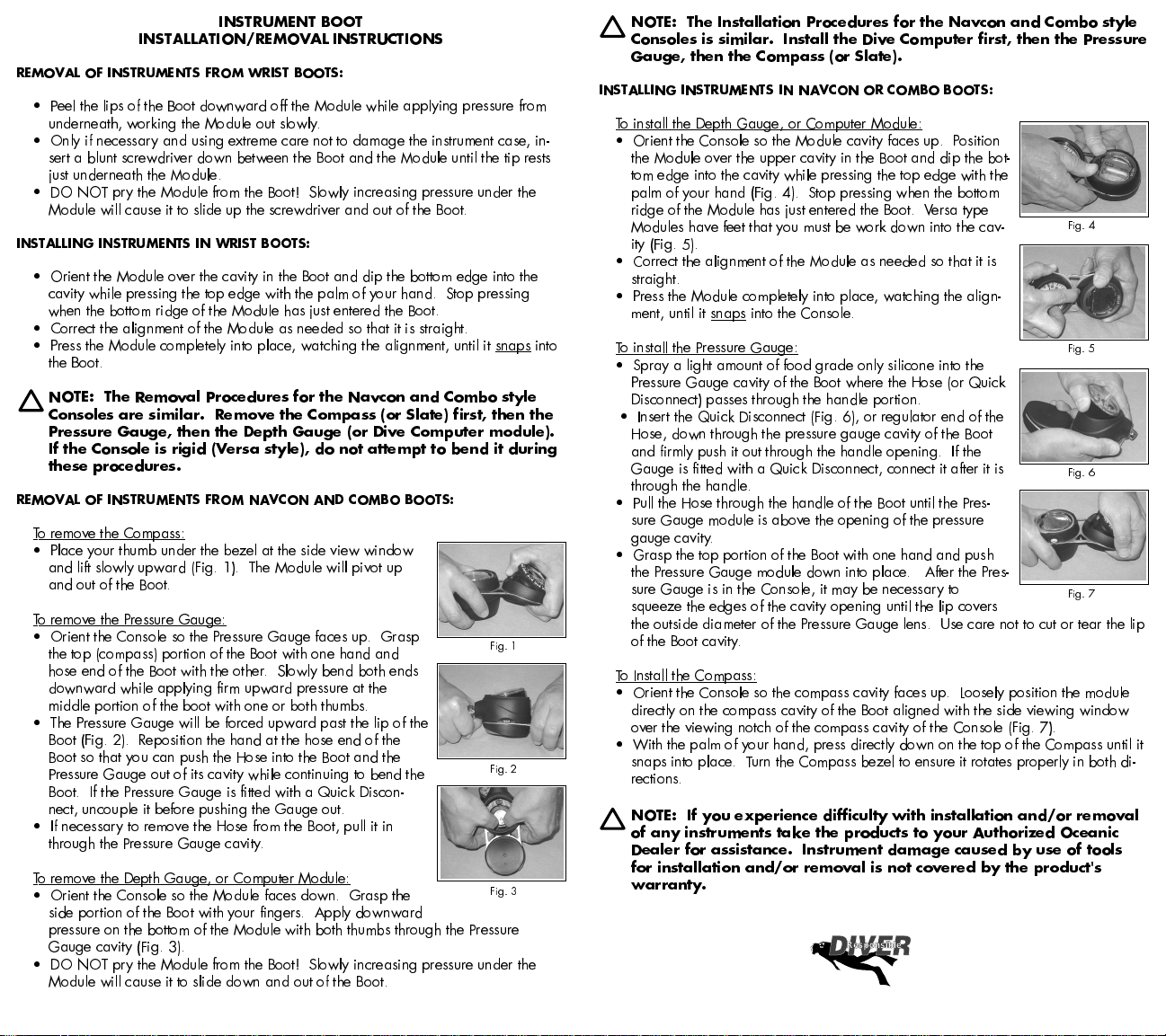
To remove the Compass:
Place your thumb under the bezel at the side view window
and lift slowly upward (Fig. 1). The Module will pivot up
and out of the Boot.
To remove the Pressure Gauge:
Orient the Console so the Pressure Gauge faces up. Grasp
the top (compass) portion of the Boot with one hand and
Fig. 1
hose end of the Boot with the other. Slowly bend both ends
downward while applying firm upward pressure at the
middle portion of the boot with one or both thumbs.
The Pressure Gauge will be forced upward past the lip of the
Boot (Fig. 2). Reposition the hand at the hose end of the
Boot so that you can push the Hose into the Boot and the
Pressure Gauge out of its cavity while continuing to bend the
Fig. 2
Boot. If the Pressure Gauge is fitted with a Quick Discon-
nect, uncouple it before pushing the Gauge out.
If necessary to remove the Hose from the Boot, pull it in
through the Pressure Gauge cavity.
To remove the Depth Gauge, or Computer Module:
Orient the Console so the Module faces down. Grasp the
Fig. 3
side portion of the Boot with your fingers. Apply downward
pressure on the bottom of the Module with both thumbs through the Pressure
Gauge cavity (Fig. 3).
DO NOT pry the Module from the Boot! Slowly increasing pressure under the
Module will cause it to slide down and out of the Boot.
NOTE: The Installation Procedures for the Navcon and Combo style
Consoles is similar. Install the Dive Computer first, then the Pressure
Gauge, then the Compass (or Slate).
INSTALLING INSTRUMENTS IN NAVCON OR COMBO BOOTS:
To install the Depth Gauge, or Computer Module:
Orient the Console so the Module cavity faces up. Position
the Module over the upper cavity in the Boot and dip the bot-
tom edge into the cavity while pressing the top edge with the
palm of your hand (Fig. 4). Stop pressing when the bottom
ridge of the Module has just entered the Boot. Versa type
Modules have feet that you must be work down into the cav-
Fig. 4
ity (Fig. 5).
Correct the alignment of the Module as needed so that it is
straight.
Press the Module completely into place, watching the align-
ment, until it snaps into the Console.
To install the Pressure Gauge:
Fig. 5
Spray a light amount of food grade only silicone into the
Pressure Gauge cavity of the Boot where the Hose (or Quick
Disconnect) passes through the handle portion.
Insert the Quick Disconnect (Fig. 6), or regulator end of the
Hose, down through the pressure gauge cavity of the Boot
and firmly push it out through the handle opening. If the
Gauge is fitted with a Quick Disconnect, connect it after it is
through the handle.
Fig. 6
Pull the Hose through the handle of the Boot until the Pres-
sure Gauge module is above the opening of the pressure
gauge cavity.
Grasp the top portion of the Boot with one hand and push
the Pressure Gauge module down into place. After the Pres-
sure Gauge is in the Console, it may be necessary to
squeeze the edges of the cavity opening until the lip covers
Fig. 7
the outside diameter of the Pressure Gauge lens. Use care not to cut or tear the lip
of the Boot cavity.
To Install the Compass:
Orient the Console so the compass cavity faces up. Loosely position the module
directly on the compass cavity of the Boot aligned with the side viewing window
over the viewing notch of the compass cavity of the Console (Fig. 7).
With the palm of your hand, press directly down on the top of the Compass until it
snaps into place. Turn the Compass bezel to ensure it rotates properly in both di-
rections.
NOTE: If you experience difficulty with installation and/or removal
of any instruments take the products to your Authorized Oceanic
Dealer for assistance. Instrument damage caused by use of tools
for installation and/or removal is not covered by the product's
warranty.
Responsible
 Loading...