

Page 1

Page 2
NOTICE
STORAGE and INITIAL ACTIVATION
Beginning with firmware revision 2E, ATOM Watch/Dive Computers are placed
in a Deep Sleep mode prior to being shipped from the factory. The intent is to
extend storage life of the Battery for up to 7 years, before the unit is initially
placed in service.
In this mode, Date and Time are updated as they normally would be. However,
they are not displayed. Upon waking the ATOM up, the correct Date and
Pacific Time will be displayed and it will be ready to operate with full functions.
To wake the ATOM up from Deep Sleep mode, simultaneously depress the
upper/right (S) and lower/left (A) buttons for 2 to 3 seconds until the display
comes full ON displaying the MAIN TIME screen, then release them.
NOTE: Once the ATOM is brought out of the Deep Sleep
mode, it can only be placed back in it by the factory .
2
Page 3

CONTENTS
WARRANTY, NOTICES, DECOMPRESSION MODEL ....................................................................................................7
FULL DISPLAY ................................................................................................................................................................. 8
INTRODUCTION AND GENERAL FEATURES AND DISPLAYS .................................................................................... 9
INTERACTIVE CONTROL CONSOLE ..................................................................................................................... 10
OPERATING MODE STRUCTURE ........................................................................................................................... 11
OPERATION AS A DIVE COMPUTER ...................................................................................................................... 12
PC INTERFACE ......................................................................................................................................................... 13
SYMBOLS AND ALPHA NUMERIC GRAPHICS ...................................................................................................... 13
AUDIBLE ALARM ...................................................................................................................................................... 14
BACKLIGHT .............................................................................................................................................................. 16
POWER SUPPLY ...................................................................................................................................................... 16
WATCH FEATURES AND DISPLAYS ............................................................................................................................ 19
LOCAL DEFAULT TIME ............................................................................................................................................ 20
MAIN TIME ................................................................................................................................................................. 21
SET MAIN TIME ......................................................................................................................................................... 22
ALTERNATE TIME ..................................................................................................................................................... 25
SET ALTERNATE TIME ............................................................................................................................................. 26
COUNTDOWN TIMER ............................................................................................................................................... 27
SET COUNTDOWN TIMER ...................................................................................................................................... 28
CHRONOGRAPH ...................................................................................................................................................... 29
DAILY ALARM ........................................................................................................................................................... 31
SET DAILY ALARM .................................................................................................................................................... 32
DIVE COMPUTER FEATURES AND DISPLAYS ........................................................................................................... 33
BAR GRAPH .............................................................................................................................................................. 34
ALPHA / NUMERIC DISPLAYS ................................................................................................................................ 36
Tank Pressure Display .......................................................................................................................................... 36
Depth Displays ...................................................................................................................................................... 36
Time and Date Displays ....................................................................................................................................... 37
Temperature Display ............................................................................................................................................. 38
3
Page 4

CONTENTS (continued)
DIVE COMPUTER SURFACE SEQUENCE AND OPERATING MODES...................................................................... 39
SURFACE MODE ...................................................................................................................................................... 40
Normal Surface Main Display ............................................................................................................................... 41
Normal Surface Main Button Operations ............................................................................................................. 43
ATOM Battery Status .......................................................................................................................................... 44
Transmitter Status .............................................................................................................................................. 45
Normal Surface Secondary Display ..................................................................................................................... 45
Normal Surface Alternate Display ........................................................................................................................ 46
NORMAL AND GAUGE SURFACE SET MODES .................................................................................................... 47
SET F GROUP (FO2) ................................................................................................................................................ 47
Set FO2 for NORM Nitrox Dives .......................................................................................................................... 48
Set FO2 GAS 1 ..................................................................................................................................................... 50
Set FO2 GAS 2 ..................................................................................................................................................... 51
Set FO2 GAS 3 ..................................................................................................................................................... 52
Set FO2 50% Default ........................................................................................................................................... 53
SET A GROUP (NORM/GAUG ALARMS) ................................................................................................................ 54
Set Audible Alarm ................................................................................................................................................. 55
Set Depth Alarm ................................................................................................................................................... 56
Set EDT (Elapsed Dive Time) Alarm ................................................................................................................... 57
Set TLBG (Tissue Loading Bar Graph) Alarm ...................................................................................................... 58
Set DTR (Dive Time Remaining) Alarm................................................................................................................ 59
Set Turn Pressure Alarm (TMT1) ......................................................................................................................... 60
Set End Pressure Alarm ....................................................................................................................................... 61
Set PO2 Alarm ...................................................................................................................................................... 62
SET U GROUP (UTILITIES) ...................................................................................................................................... 63
Set Wet Activation ................................................................................................................................................ 64
Set Units of Measure ............................................................................................................................................ 65
Set NORM Safety Stop ......................................................................................................................................... 66
Set Conservative Factor ....................................................................................................................................... 67
Set Backlight Duration .......................................................................................................................................... 68
Set Sampling Rate ................................................................................................................................................ 69
4
Page 5

CONTENTS (continued)
Set TMT1 (Transmitter 1 Link Code) .................................................................................................................... 70
Set TMT (Transmitter) 2-3 Use ............................................................................................................................ 72
Set TMT2 (Transmitter 2 Link Code) ................................................................................................................... 73
Set TMT3 (Transmitter 3 Link Code) ................................................................................................................... 75
SERIAL NUMBER (ATOM) ........................................................................................................................................ 77
NORM (Normal Dive) PLAN MODE ......................................................................................................................... 78
FLY MODE ................................................................................................................................................................. 81
SAT MODE (NORM) .................................................................................................................................................. 82
NORM/GAUG LOG MODE ........................................................................................................................................ 83
HISTORY MODE (NORM/GAUG) ............................................................................................................................ 87
OVERVIEW OF DIVE MODE INFORMATION ............................................................................................................... 91
POSITIONING OF THE ATOM .................................................................................................................................. 93
Link Interruption Underwater ................................................................................................................................ 93
DIVE TIME REMAINING (DTR) ................................................................................................................................. 94
No Decompression Dive Time Remaining (NDC) ................................................................................................ 95
Oxygen Accumulation Time Remaining (OTR) .................................................................................................... 96
Air Time Remaining (ATR) .................................................................................................................................... 96
Air Time Remaining Alarm .................................................................................................................................... 97
VARIABLE ASCENT RATE ....................................................................................................................................... 98
ELAPSED DIVE TIME ............................................................................................................................................... 99
CONTROL OF DISPLAYS ......................................................................................................................................... 99
NORM TYPE DIVE MODES (AIR/NITROX) ................................................................................................................. 101
WET CONTACTS ..................................................................................................................................................... 102
NORM NO DECOMPRESSION DIVE MODE ......................................................................................................... 103
NORM Dive No Deco Safety Stop ..................................................................................................................... 106
DECOMPRESSION DIVE MODE ............................................................................................................................ 107
VIOLATION MODES ................................................................................................................................................ 111
HIGH PO2 ................................................................................................................................................................ 116
HIGH OXYGEN ACCUMULATION.......................................................................................................................... 117
SUMMARY OF WARNING AND ALARM MESSAGES .......................................................................................... 118
5
Page 6

CONTENTS (continued)
SWITCHING GAS MIXES AND BUDDY PRESSURE CHECK....................................................................................119
SWITCHING GAS MIXES (NORM ONLY) .............................................................................................................. 120
BUDDY PRESSURE CHECK (NORM ONLY) ......................................................................................................... 125
NORM POST DIVE MODES ......................................................................................................................................... 129
TRANSITION PERIOD ............................................................................................................................................ 130
AFTER THE TRANSITION PERIOD ....................................................................................................................... 131
GAUGE OPERATING MODE ....................................................................................................................................... 133
GAUG SURFACE DISPLAYS.................................................................................................................................. 134
GAUG DIVE DISPLAYS .......................................................................................................................................... 135
FREE DIVE OPERATING MODE ................................................................................................................................. 137
FREE SURFACE DISPLAYS ................................................................................................................................... 138
FREE COUNTDOWN TIMER (CDT) ....................................................................................................................... 140
SET FREE CDT ....................................................................................................................................................... 142
SET FREE ALARMS (EDT, FDA) ............................................................................................................................ 143
FREE DIVE DISPLAYS............................................................................................................................................ 148
REFERENCE ................................................................................................................................................................. 153
UPLOADING SETTINGS AND DOWNLOADING DATA ........................................................................................ 154
CARE AND CLEANING ........................................................................................................................................... 156
INSPECTIONS AND SERVICE ............................................................................................................................... 156
BATTERY REPLACEMENT .................................................................................................................................... 158
INSTALLING A TRANSMITTER ON A REGULATOR ............................................................................................ 164
TRANSMITTER COMPATIBILITY WITH NITROX .................................................................................................. 164
ALTITUDE SENSING AND ADJUSTMENT ............................................................................................................ 165
CHARTS OF NO DECOMPRESSION LIMITS AT ALTITUDE ................................................................................ 166
CHART OF OXYGEN EXPOSURE LIMITS ............................................................................................................ 167
SPECIFICATIONS ................................................................................................................................................... 168
INSPECTION/ SERVICE RECORD ......................................................................................................................... 174
OCEANIC WORLD WIDE ....................................................................................................................................... 175
6
Page 7
LIMITED TWO-YEAR WARRANTY
For details, refer to the Product Warranty Registration Card provided. Register on-line at www.OceanicWorldwide.com
COPYRIGHT NOTICE
This operating manual is copyrighted, all rights are reserved. It may not, in whole or in part, be copied, photocopied,
reproduced, translated, or reduced to any electronic medium or machine readable form without prior consent in writing
from Oceanic / 2002 Design.
ATOM 2.0 Operating Manual, Doc. No. 12-2698
TRADEMARK, TRADE NAME, AND SERVICE MARK NOTICE
Oceanic, the Oceanic logotype, the Oceanic 'O' symbol, ATOM, the ATOM 2.0 logo, Air Time Remaining (ATR), Diver
Replaceable Batteries, Graphic Diver Interface, Tissue Loading Bar Graph (TLBG), Pre Dive Planning Sequence (PDPS),
Set Point, Control Console, Turn Gas Alarm, and OceanLog are all registered and unregistered trademarks , trade
names, and service marks of Oceanic. All rights are reserved.
PATENT NOTICE
U.S. Patents have been issued, or applied for, to protect the following design features:
Air Time Remaining (U.S. Patent no. 4,586,136 and 6,543,444) and Data Sensing and Processing Device (U.S. Patent
no. 4,882,678). Set TLBG Alarm and other patents pending. User Setable Display (U.S. Patent no. 5,845,235) is
owned by Suunto Oy (Finland).
DECOMPRESSION MODEL
The programs within the ATOM simulate the absorption of nitrogen into the body by using a mathematical model. This
model is merely a way to apply a limited set of data to a large range of experiences. The ATOM dive computer model
is based upon the latest research and experiments in decompression theory.
the U.S. Navy (or other) No Decompression Tables, is no guarantee of avoiding decompression
sickness, i.e. the bends.
can predict how your body will react to a particular dive profile.
Every divers physiology is different, and can even vary from day to day. No machine
© 2002 Design, 2005
San Leandro, CA USA 94577
Still, using the ATOM, just as using
7
Page 8
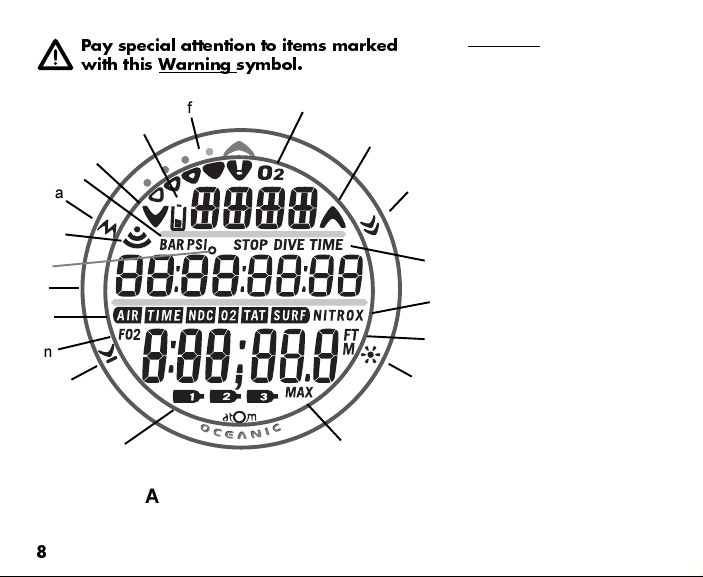
Pay special attention to items marked
with this Warning symbol.
f
t
s
r
a
q
p
e
o
n
d
m
ATOM 2.0 FULL LCD
8
Components:
a. Mode (M) Button
b. Select (S) Button
c. Light (L) Button
g
h
d. Advance (A) Button
e. LED Warning Light
f. Bar Graph
g. Icon - indicates O2BG
h. Icon - Ascend Arrow
i. Symbol - STOP TIME
b
j. Symbol - NITROX (Mode)
k. Symbol - FT or M (Depth)
l. Symbol - MAX
m. Icons - Tank 1, 2, 3
n. Symbol - FO2
i
o. Symbols - AIR TIME
j
k
p. Icon - degrees (Temperature)
q. Icon - Daily Alarm, or -
c
Transmitter Link
r. Symbol - PSI or BAR (Pressure)
s. Icon - Descend Arrow
t. Icon - Low Battery
DIVE TIME
TIME NDC
TIME O2
TIME TAT
TIME SURF
l
Page 9

WARNING: Prior to diving with the ATOM 2.0,
you must also read and understand the Oce-
anic Dive Computer Safety and Reference
Manual, Doc. No. 12-2262, which provides
Important Warnings and Safety Recommenda-
tions as well as general product information.
INTRODUCTION
GENERAL FEATURES AND DISPLAYS
AND
9
Page 10
INTRODUCTION
Welcome to OCEANIC and thank you for choosing the ATOM 2.0 !
It is extremely important that you read this Operating Manual in sequence and understand
it completely before attempting to use the ATOM 2.0 as a dive computer.
It is equally important that you read the Oceanic Dive Computer Safety and Reference
Manual (Doc. No. 12-2262) provided with your ATOM 2.0. It contains information that
you must become familiar with prior to diving with your ATOM 2.0.
Remember that technology is no substitute for common sense, and a dive computer only
provides the person using it with data, not the knowledge to use it.
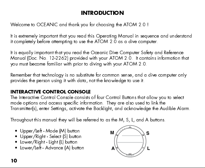
INTERACTIVE CONTROL CONSOLE
The Interactive Control Console consists of four Control Buttons that allow you to select
mode options and access specific information. They are also used to link the
Transmitter(s), enter Settings, activate the Backlight, and acknowledge the Audible Alarm.
Throughout this manual they will be referred to as the M, S, L, and A buttons.
Upper/Left - Mode (M) button
Upper/Right - Select (S) button
Lower/Right - Light (L) button
Lower/Left - Advance (A) button
10
M
A
S
L
Page 11
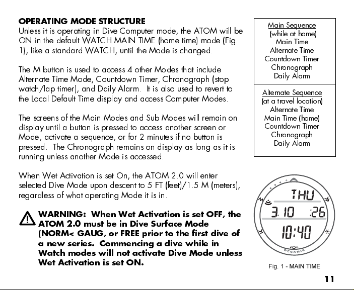
OPERATING MODE STRUCTURE
Unless it is operating in Dive Computer mode, the ATOM will be
ON in the default WATCH MAIN TIME (home time) mode (Fig.
1), like a standard WATCH, until the Mode is changed.
The M button is used to access 4 other Modes that include
Alternate Time Mode, Countdown Timer, Chronograph (stop
watch/lap timer), and Daily Alarm. It is also used to revert to
the Local Default Time display and access Computer Modes.
The screens of the Main Modes and Sub Modes will remain on
display until a button is pressed to access another screen or
Mode, activate a sequence, or for 2 minutes if no button is
pressed. The Chronograph remains on display as long as it is
running unless another Mode is accessed.
When Wet Activation is set On, the ATOM 2.0 will enter
selected Dive Mode upon descent to 5 FT (feet)/1.5 M (meters),
regardless of what operating Mode it is in.
WARNING: When Wet Activation is set OFF, the
ATOM 2.0 must be in Dive Surface Mode
(NORM< GAUG, or FREE prior to the first dive of
a new series. Commencing a dive while in
Watch modes will not activate Dive Mode unless
Wet Activation is set ON.
Main Sequence
(while at home)
Main Time
Alternate Time
Countdown Timer
Chronograph
Daily Alarm
Alternate Sequence
(at a travel location)
Alternate Time
Main Time (home)
Countdown Timer
Chronograph
Daily Alarm
Fig. 1 - MAIN TIME
11
Page 12
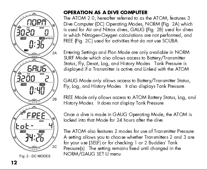
Fig. 2 - DC MODES
12
OPERATION AS A DIVE COMPUTER
The ATOM 2.0, hereafter referred to as the ATOM, features 3
Dive Computer (DC) Operating Modes, NORM (Fig. 2A) which
is used for Air and Nitrox dives, GAUG (Fig. 2B) used for dives
in which Nitrogen-Oxygen calculations are not performed, and
FREE (Fig. 2C) used for activities that do not use SCUBA.
Entering Settings and Plan Mode are only available in NORM
2A
SURF Mode which also allows access to Battery/Transmitter
Status, Fly, Desat, Log, and History Modes. Tank Pressure is
displayed if a Transmitter is active and Linked with the ATOM.
GAUG Mode only allows access to Battery/Transmitter Status,
Fly, Log, and History Modes. It also displays Tank Pressure.
FREE Mode only allows access to ATOM Battery Status, Log, and
2B
History Modes. It does not display Tank Pressure.
Once a dive is made in GAUG Operating Mode, the ATOM is
locked into that Mode for 24 hours after the dive.
The ATOM also features 2 modes for use of Transmitter Pressure.
A setting allows you to choose whether Transmitters 2 and 3 are
for your use (SELF) or for checking 1 or 2 Buddies' Tank
2C
Pressure(s). The setting remains fixed until changed in the
NORM/GAUG SET U menu.
Page 13
PC INTERFACE
Interface with a PC is accomplished by connecting the ATOM to a PC USB Port using the
USB Interface Cable provided. The same Cable is used for Upload and Download.
The software program is on the CD provided, together with a USB Driver. The program's
Help serves as the user manual and can be printed for personal use. The Settings Upload
program is used to check the ATOM's existing Settings and for entering Time, Alarm, and
Dive Computer settings into the ATOM. The Data Download program is used to retrieve
Data that was sampled during dives and stored in the ATOM's memory.
The ATOM checks for an External Access request once every second while in the Watch
Main Time. Checks are not made if the unit is WET. For a connection to be made, the
Interface Cable is clipped onto the ATOM's Data Port and plugged into a PC USB Port. To
establish the connection, the PC program must be running. When the connection is made,
all segments of the ATOM appear on the display until completion of the Upload or Down-
load operation.
The ATOM reverts to the Watch Main Time screen after completion of the Upload or
Download operation, or after 2 minutes if no PC action was taken.
SYMBOLS AND ALPHA NUMERIC GRAPHICS
The upper line of digits on the LCD screen is used to convey alpha Messages such as Day
of the Week, Operating Modes, items being Set, Gas and Transmitter identification,
Altitude level, and Alarm identification. At times, the second line is also used to display
alpha numeric graphics such as PO2 and On/Off. The FO2 setting of a selected Gas will
appear in the lower line.
13
Page 14
AUDIBLE ALARM
Most warning situations that activate the Audible Alarm while operating in NORM or
GAUG Mode cause the ATOM to emit 1 beep per second for 10 seconds, or until the
situation is corrected, or it is acknowledged by momentarily pressing and releasing the S
button (less than 2 seconds). After being acknowledged and the situation corrected, the
Alarm will sound again upon reentry into the warning situation, or entry into another type
of warning situation.
FREE Dive Mode has its own set of Alarms which emit 3 short beeps either 1 or 3 times
which cannot be acknowledged or set Off.
A red LED Warning Light, located on the left side of the housing, is synchronized with the
Audible Alarm. It will flash as the Audible Alarm sounds. It will turn Off when the Alarm is
acknowledged or the situation is corrected. The Audible and LED will not be active if the
Alarm is Set OFF (a group A setting).
Situations that will activate the NORM/GAUG 10 second Alarm include -
Air Time Remaining (ATR) at 5 minutes, then again at 0 minutes.
ATR becomes less than No Deco and O2 Time Remaining for 1 minute.
Turn Pressure at the Set Point selected (Transmitter 1).
End Pressure at the Set Point selected (active Transmitter).
Descent deeper than the Max Depth Set Point selected.
Dive Time Remaining at the Set Point selected.
Elapsed Dive Time at the Set Point selected.
High PO2 of 1.60 ATA or the Set Point selected.
High O2 of 300 OTU (single or daily exposure).
14
Page 15
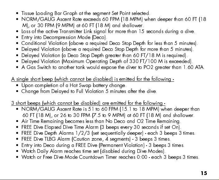
Tissue Loading Bar Graph at the segment Set Point selected.
NORM/GAUG Ascent Rate exceeds 60 FPM (18 MPM) when deeper than 60 FT (18
M), or 30 FPM (9 MPM) at 60 FT (18 M) and shallower.
Loss of the active Transmitter Link signal for more than 15 seconds during a dive.
Entry into Decompression Mode (Deco).
Conditional Violation (above a required Deco Stop Depth for less than 5 minutes).
Delayed Violation (above a required Deco Stop Depth for more than 5 minutes).
Delayed Violation (a Deco Stop Depth greater than 60 FT/18 M is required).
Delayed Violation (Maximum Operating Depth of 330 FT/100 M is exceeded).
A Gas Switch to another tank would expose the diver to PO2 greater than 1.60 ATA.
A single short beep (which cannot be disabled) is emitted for the following -
Upon completion of a Hot Swap battery change.
Change from Delayed to Full Violation 5 minutes after the dive.
3 short beeps (which cannot be disabled) are emitted for the following -
NORM/GAUG Ascent Rate is 51 to 60 FPM (15.1 to 18 MPM) when deeper than
60 FT (18 M), or 26 to 30 FPM (7.5 to 9 MPM) at 60 FT (18 M) and shallower.
Air Time Remaining becomes less than No Deco and O2 Time Remaining.
FREE Dive Elapsed Dive Time Alarm (3 beeps every 30 seconds if set On).
FREE Dive Depth Alarms 1/2/3 (set sequentially deeper) - each 3 beeps 3 times.
FREE Dive TLBG Alarm (Caution zone, 4 segments) - 3 beeps 3 times.
Entry into Deco during a FREE Dive (Permanent Violation) - 3 beeps 3 times.
Watch Daily Alarm reaches time set (disabled during Dive Modes).
Watch or Free Dive Mode Countdown Timer reaches 0:00 - each 3 beeps 3 times.
15
Page 16
During the following NORM Dive situations, the 10 second continuous tone will be fol-
lowed by a 5 second steady beep that will not turn off when acknowledged -
Ascending above a required Decompression Ceiling Stop Depth for more than 5
minutes (referred to as a Delayed Violation).
Decompression requires a Ceiling Stop Depth of 70 FT/21 M or deeper.
Being on the Surface for 5 minutes after a Conditional Violation (Permanent
Violation).
BACKLIGHT
To activate the Backlight - press the L button.
The Backlight will activate and illuminate the display for button depression time* plus
the user set Duration time of 0, 5, or 10 seconds, for a maximum of 20 seconds.
(*The Backlight will turn Off if the button is held depressed for more than 10
seconds.)
Press the button again to activate as desired.
NOTE: Extensive use of the Backlight reduces estimated Battery life.
Also, the Backlight does not operate during a Low ATOM Battery
Condition or when the ATOM is connected to a PC.
POWER SUPPLY
The ATOM (Watch) utilizes one 3 volt CR2430 Lithium Battery. When used as a Dive
Computer, the ATOM's battery should operate normally for 1 year or 300 dive hours if 2
dives are conducted during each dive period. The ATOM checks its battery voltage every
2 minutes during surface operation.
16
Page 17
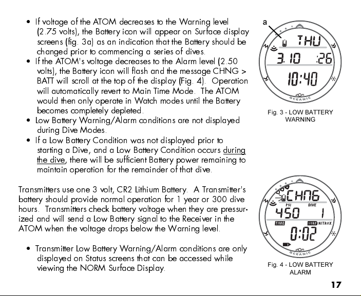
If voltage of the ATOM decreases to the Warning level
(2.75 volts), the Battery icon will appear on Surface display
screens (fig. 3a) as an indication that the Battery should be
changed prior to commencing a series of dives.
If the ATOM's voltage decreases to the Alarm level (2.50
volts), the Battery icon will flash and the message CHNG >
BATT will scroll at the top of the display (Fig. 4). Operation
will automatically revert to Main Time Mode. The ATO M
would then only operate in Watch modes until the Battery
becomes completely depleted.
Low Battery Warning/Alarm conditions are not displayed
during Dive Modes.
If a Low Battery Condition was not displayed prior to
starting a Dive, and a Low Battery Condition occurs during
the dive, there will be sufficient Battery power remaining to
maintain operation for the remainder of that dive.
Transmitters use one 3 volt, CR2 Lithium Battery. A Transmitter's
battery should provide normal operation for 1 year or 300 dive
hours. Transmitters check battery voltage when they are pressur-
ized and will send a Low Battery signal to the Receiver in the
ATOM when the voltage drops below the Warning level.
Transmitter Low Battery Warning/Alarm conditions are only
displayed on Status screens that can be accessed while
viewing the NORM Surface Display.
a
Fig. 3 - LOW BATTERY
WARNING
Fig. 4 - LOW BATTERY
ALARM
17
Page 18
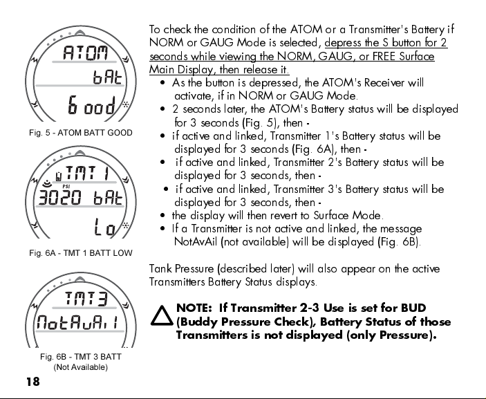
Fig. 5 - ATOM BATT GOOD
Fig. 6A - TMT 1 BATT LOW
Fig. 6B - TMT 3 BATT
(Not Available)
18
To check the condition of the ATOM or a Transmitter's Battery if
NORM or GAUG Mode is selected, depress the S button for 2
seconds while viewing the NORM, GAUG, or FREE Surface
Main Display, then release it.
As the button is depressed, the ATOM's Receiver will
activate, if in NORM or GAUG Mode.
2 seconds later, the ATOM's Battery status will be displayed
for 3 seconds (Fig. 5), then -
if active and linked, Transmitter 1's Battery status will be
displayed for 3 seconds (Fig. 6A), then -
if active and linked, Transmitter 2's Battery status will be
displayed for 3 seconds, then -
if active and linked, Transmitter 3's Battery status will be
displayed for 3 seconds, then -
the display will then revert to Surface Mode.
If a Transmitter is not active and linked, the message
NotAvAil (not available) will be displayed (Fig. 6B).
Tank Pressure (described later) will also appear on the active
Transmitters Battery Status displays.
NOTE: If Transmitter 2-3 Use is set for BUD
(Buddy Pressure Check), Battery Status of those
Transmitters is not displayed (only Pressure).
Page 19

WARNING: Prior to diving with the ATOM,
you must also read and understand the Oce-
anic Dive Computer Safety and Reference
Manual, Doc. No. 12-2262, which provides
Important Warnings and Safety Recommenda-
tions as well as general product information.
FEA TURES AND DISPLAYS
WATCH
19
Page 20
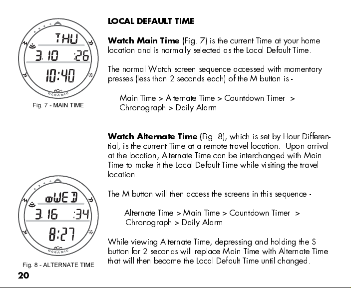
LOCAL DEFAULT TIME
Fig. 7 - MAIN TIME
Fig. 8 - ALTERNATE TIME
20
Watch Main Time
(Fig. 7) is the current Time at your home
location and is normally selected as the Local Default Time.
The normal Watch screen sequence accessed with momentary
presses (less than 2 seconds each) of the M button is -
Main Time > Alternate Time > Countdown Timer >
Chronograph > Daily Alarm
Watch Alternate Time
(Fig. 8), which is set by Hour Differen-
tial, is the current Time at a remote travel location. Upon arrival
at the location, Alternate Time can be interchanged with Main
Time to make it the Local Default Time while visiting the travel
location.
The M button will then access the screens in this sequence -
Alternate Time > Main Time > Countdown T imer >
Chronograph > Daily Alarm
While viewing Alternate Time, depressing and holding the S
button for 2 seconds will replace Main Time with Alternate Time
that will then become the Local Default Time until changed.
Page 21
While viewing any of the Watch Mode displays, pressing and
holding the M button for 2 seconds or if no button is pressed for
2 minutes, operation will revert to the Watch Time screen se-
lected to be the Local Default Watch Time (Main or Alternate).
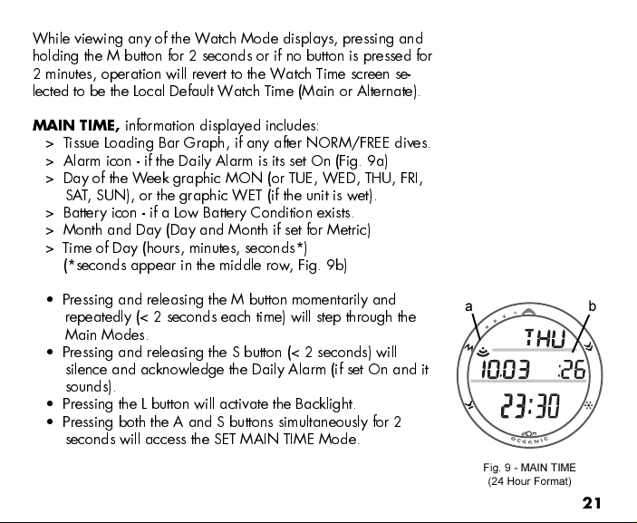
MAIN TIME,
information displayed includes:
> Tissue Loading Bar Graph, if any after NORM/FREE dives.
> Alarm icon - if the Daily Alarm is its set On (Fig. 9a)
> Day of the Week graphic MON (or TUE, WED, THU, FRI,
SAT, SUN), or the graphic WET (if the unit is wet).
> Battery icon - if a Low Battery Condition exists.
> Month and Day (Day and Month if set for Metric)
> Time of Day (hours, minutes, seconds*)
(*seconds appear in the middle row, Fig. 9b)
Pressing and releasing the M button momentarily and
repeatedly (< 2 seconds each time) will step through the
Main Modes.
Pressing and releasing the S button (< 2 seconds) will
silence and acknowledge the Daily Alarm (if set On and it
sounds).
Pressing the L button will activate the Backlight.
Pressing both the A and S buttons simultaneously for 2
seconds will access the SET MAIN TIME Mode.
a b
Fig. 9 - MAIN TIME
(24 Hour Format)
21
Page 22
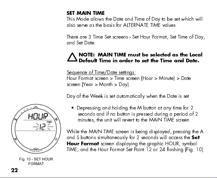
Fig. 10 - SET HOUR
FORMAT
22
SET MAIN TIME
This Mode allows the Date and Time of Day to be set which will
also serve as the basis for ALTERNATE TIME values.
There are 3 Time Set screens - Set Hour Format, Set Time of Day,
and Set Date.
NOTE: MAIN TIME must be selected as the Local
Default Time in order to set the Time and Date.
Sequence of Time/Date settings:
Hour Format screen > Time screen (Hour > Minute) > Date
screen (Year > Month > Day)
Day of the Week is set automatically when the Date is set.
Depressing and holding the M button at any time for 2
seconds and if no button is pressed during a period of 2
minutes, the unit will revert to the MAIN TIME screen.
While the MAIN TIME screen is being displayed, pressing the A
and S buttons simultaneously for 2 seconds will access the
Hour Format
screen displaying the graphic HOUR, symbol
Set
TIME, and the Hour Format Set Point 12 or 24 flashing (Fig. 10).
Page 23
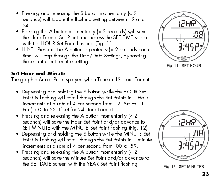
Pressing and releasing the S button momentarily (< 2
seconds) will toggle the flashing setting between 12 and
24.
Pressing the A button momentarily (< 2 seconds) will save
the Hour Format Set Point and access the SET TIME screen
with the HOUR Set Point flashing (Fig. 11).
HINT - Pressing the A button repeatedly (< 2 seconds each
time) will step through the Time/Date Settings, bypassing
those that don't require setting.
Set Hour and Minute
The graphic Am or Pm displayed when Time in 12 Hour Format.
Depressing and holding the S button while the HOUR Set
Point is flashing will scroll through the Set Points in 1 Hour
increments at a rate of 4 per second from 12: Am to 11:
Pm (or 0: to 23: if set for 24 Hour Format).
Pressing and releasing the A button momentarily (< 2
seconds) will save the Hour Set Point and/or advance to
SET MINUTE with the MINUTE Set Point flashing (Fig. 12).
Depressing and holding the S button while the MINUTE Set
Point is flashing will scroll through the Set Points in 1 minute
increments at a rate of 4 per second from :00 to :59.
Pressing and releasing the A button momentarily (< 2
seconds) will save the Minute Set Point and/or advance to
the SET DATE screen with the YEAR Set Point flashing.
Fig. 11 - SET HOUR
Fig. 12 - SET MINUTES
23
Page 24
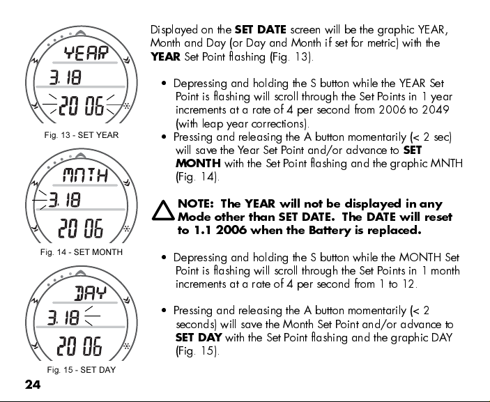
Fig. 13 - SET YEAR
Fig. 14 - SET MONTH
Fig. 15 - SET DAY
24
Displayed on the
SET DATE
screen will be the graphic YEAR,
Month and Day (or Day and Month if set for metric) with the
YEAR
Set Point flashing (Fig. 13).
Depressing and holding the S button while the YEAR Set
Point is flashing will scroll through the Set Points in 1 year
increments at a rate of 4 per second from 2006 to 2049
(with leap year corrections).
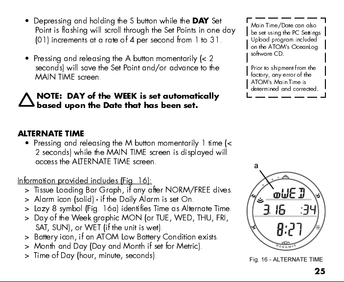
Pressing and releasing the A button momentarily (< 2 sec)
will save the Year Set Point and/or advance to
MONTH
with the Set Point flashing and the graphic MNTH
SET
(Fig. 14).
NOTE: The YEAR will not be displayed in any
Mode other than SET DATE. The DATE will reset
to 1.1 2006 when the Battery is replaced.
Depressing and holding the S button while the MONTH Set
Point is flashing will scroll through the Set Points in 1 month
increments at a rate of 4 per second from 1 to 12.
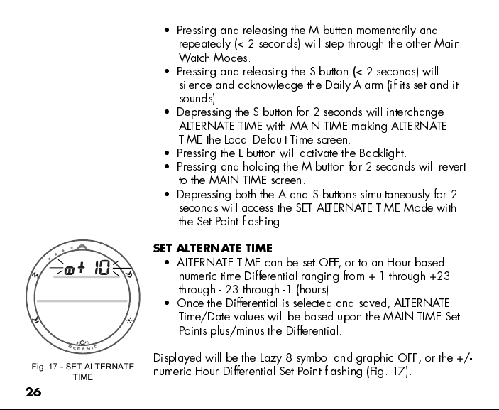
Pressing and releasing the A button momentarily (< 2
seconds) will save the Month Set Point and/or advance to
SET DAY
with the Set Point flashing and the graphic DA Y
(Fig. 15).
Page 25
Depressing and holding the S button while the
DAY
Set
Point is flashing will scroll through the Set Points in one day
(01) increments at a rate of 4 per second from 1 to 31.
Pressing and releasing the A button momentarily (< 2
seconds) will save the Set Point and/or advance to the
MAIN TIME screen.
NOTE: DAY of the WEEK is set automatically
based upon the Date that has been set.
ALTERNATE TIME
Pressing and releasing the M button momentarily 1 time (<
2 seconds) while the MAIN TIME screen is displayed will
access the ALTERNATE TIME screen.
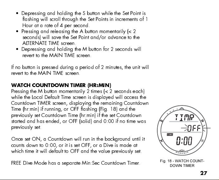
Information provided includes (Fig. 16):
> Tissue Loading Bar Graph, if any after NORM/FREE dives.
> Alarm icon (solid) - if the Daily Alarm is set On.
> Lazy 8 symbol (Fig. 16a) identifies Time as Alternate Time.
> Day of the Week graphic MON (or TUE, WED, THU, FRI,
SAT, SUN), or WET (if the unit is wet).
> Battery icon, if an ATOM Low Battery Condition exists.
> Month and Day (Day and Month if set for Metric).
> Time of Day (hour , minute, seconds).
Main Time/Date can also
be set using the PC Settings
Upload program included
on the ATOM's OceanLog
software CD.
Prior to shipment from the
factory, any error of the
ATOM's Main Time is
determined and corrected.
a
Fig. 16 - ALTERNATE TIME
25
Page 26
Pressing and releasing the M button momentarily and
repeatedly (< 2 seconds) will step through the other Main
W atch Modes.
Pressing and releasing the S button (< 2 seconds) will
silence and acknowledge the Daily Alarm (if its set and it
sounds).
Depressing the S button for 2 seconds will interchange
ALTERNATE TIME with MAIN TIME making ALTERNATE
TIME the Local Default Time screen.
Pressing the L button will activate the Backlight.
Pressing and holding the M button for 2 seconds will revert
to the MAIN TIME screen.
Depressing both the A and S buttons simultaneously for 2
seconds will access the SET ALTERNATE TIME Mode with
the Set Point flashing.
SET ALTERNATE TIME
ALTERNATE TIME can be set OFF, or to an Hour based
numeric time Differential ranging from + 1 through +23
through - 23 through -1 (hours).
Once the Differential is selected and saved, ALTERNATE
Time/Date values will be based upon the MAIN TIME Set
Points plus/minus the Differential.
Fig. 17 - SET ALTERNATE
TIME
26
Displayed will be the Lazy 8 symbol and graphic OFF, or the +/-
numeric Hour Differential Set Point flashing (Fig. 17).
Page 27
Depressing and holding the S button while the Set Point is
flashing will scroll through the Set Points in increments of 1
Hour at a rate of 4 per second.
Pressing and releasing the A button momentarily (< 2
seconds) will save the Set Point and/or advance to the
ALTERNATE TIME screen.
Depressing and holding the M button for 2 seconds will
revert to the MAIN TIME screen.
If no button is pressed during a period of 2 minutes, the unit will
revert to the MAIN TIME screen.
WATCH COUNTDOWN TIMER (HR:MIN)
Pressing the M button momentarily 2 times (< 2 seconds each)
while the Local Default Time screen is displayed will access the
Countdown TIMER screen, displaying the remaining Countdown
Time (hr:min) if running, or OFF flashing (Fig. 18) and the
previously set Countdown Time (hr:min) if the set Countdown
started and has ended, or OFF (solid) and 0:00 if no time was
previously set.
Once set ON, a Countdown will run in the background until it
counts down to 0:00, or it is set OFF, or a Dive is made at
which time it will default to OFF and the value previously set.
FREE Dive Mode has a separate Min:Sec Countdown Timer.
Fig. 18 - WATCH COUNT-
DOWN TIMER
27
Page 28
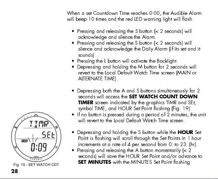
When a set Countdown Time reaches 0:00, the Audible Alarm
will beep 10 times and the red LED warning light will flash.
Pressing and releasing the S button (< 2 seconds) will
acknowledge and silence the Alarm.
Pressing and releasing the S button (< 2 seconds) will
silence and acknowledge the Daily Alarm (if its set and it
sounds).
Pressing the L button will activate the Backlight.
Depressing and holding the M button for 2 seconds will
revert to the Local Default Watch Time screen (MAIN or
ALTERNATE TIME).
Depressing both the A and S buttons simultaneously for 2
seconds will access the
TIMER
screen indicated by the graphics TIMR and SEt,
SET WATCH COUNT DOWN
symbol TIME, and HOUR Set Point flashing (Fig. 19).
If no button is pressed during a period of 2 minutes, the unit
will revert to the Local Default Watch Time screen.
Fig. 19 - SET WATCH CDT
28
Depressing and holding the S button while the
HOUR
Point is flashing will scroll through the Set Points in 1 hour
increments at a rate of 4 per second from 0: to 23: (hr).
Pressing and releasing the A button momentarily (< 2
seconds) will save the HOUR Set Point and/or advance to
SET MINUTES
with the MINUTES Set Point flashing.
Set
Page 29
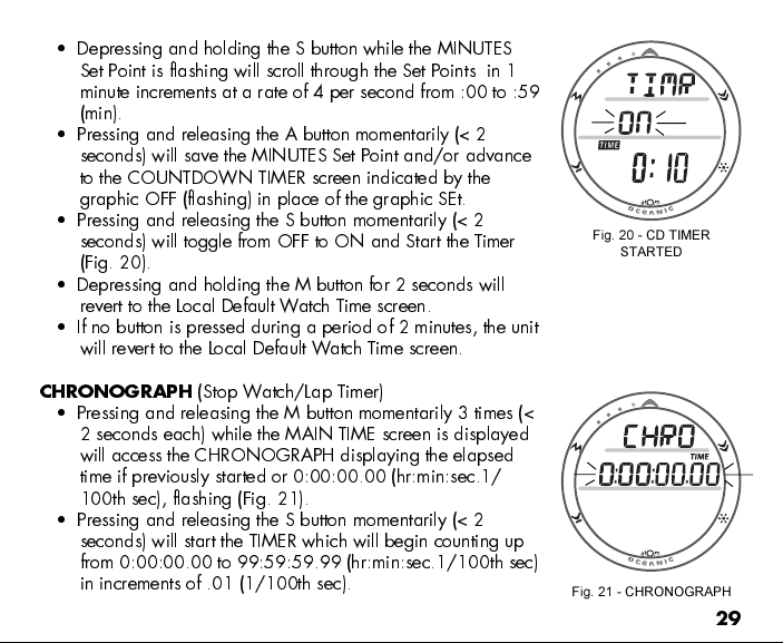
Depressing and holding the S button while the MINUTES
Set Point is flashing will scroll through the Set Points in 1
minute increments at a rate of 4 per second from :00 to :59
(min).
Pressing and releasing the A button momentarily (< 2
seconds) will save the MINUTES Set Point and/or advance
to the COUNTDOWN TIMER screen indicated by the
graphic OFF (flashing) in place of the graphic SEt.
Pressing and releasing the S button momentarily (< 2
seconds) will toggle from OFF to ON and Start the Timer
(Fig. 20).
Depressing and holding the M button for 2 seconds will
revert to the Local Default Watch Time screen.
If no button is pressed during a period of 2 minutes, the unit
will revert to the Local Default Watch Time screen.
Fig. 20 - CD TIMER
STARTED
CHRONOGRAPH
(Stop Watch/Lap Timer)
Pressing and releasing the M button momentarily 3 times (<
2 seconds each) while the MAIN TIME screen is displayed
will access the CHRONOGRAPH displaying the elapsed
time if previously started or 0:00:00.00 (hr:min:sec.1/
100th sec), flashing (Fig. 21).
Pressing and releasing the S button momentarily (< 2
seconds) will start the TIMER which will begin counting up
from 0:00:00.00 to 99:59:59.99 (hr:min:sec.1/100th sec)
in increments of .01 (1/100th sec).
Fig. 21 - CHRONOGRAPH
29
Page 30
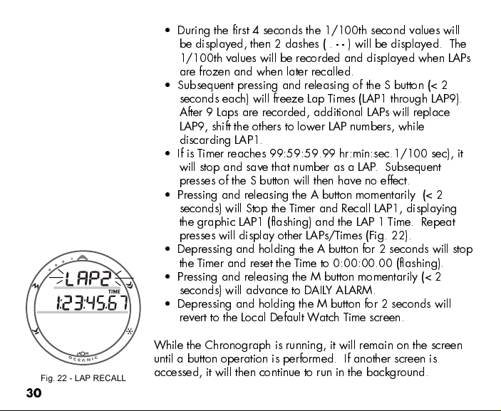
Fig. 22 - LAP RECALL
30
During the first 4 seconds the 1/100th second values will
be displayed, then 2 dashes ( . - - ) will be displayed. The
1/100th values will be recorded and displayed when LAPs
are frozen and when later recalled.
Subsequent pressing and releasing of the S button (< 2
seconds each) will freeze Lap Times (LAP1 through LAP9).
After 9 Laps are recorded, additional LAPs will replace
LAP9, shift the others to lower LAP numbers, while
discarding LAP1.
If is Timer reaches 99:59:59.99 hr:min:sec.1/100 sec), it
will stop and save that number as a LAP. Subsequent
presses of the S button will then have no effect.
Pressing and releasing the A button momentarily (< 2
seconds) will Stop the Timer and Recall LAP1, displaying
the graphic LAP1 (flashing) and the LAP 1 Time. Repeat
presses will display other LAPs/Times (Fig. 22).
Depressing and holding the A button for 2 seconds will stop
the Timer and reset the Time to 0:00:00.00 (flashing).
Pressing and releasing the M button momentarily (< 2
seconds) will advance to DAILY ALARM.
Depressing and holding the M button for 2 seconds will
revert to the Local Default Watch Time screen.
While the Chronograph is running, it will remain on the screen
until a button operation is performed. If another screen is
accessed, it will then continue to run in the background.
Page 31

Upon descending on a dive, the Chronograph operation will be
terminated and reset to 0:00:00.0.
DAILY ALARM
When set ON, the DAILY ALARM will sound the Audible Alarm
and flash the Red LED at the Time set every day.
Pressing the M button momentarily 4 times (< 2 seconds
each time) while the MAIN TIME screen is displayed will
access the DAILY ALARM STATUS screen.
DAILY ALARM STATUS, information provided includes (Fig. 23):
> Alarm icon
> Graphics ALRM and ON (or OFF), flashing.
> Alarm Time Set Point (hr:min).
Pressing and releasing the S button momentarily (< 2
seconds) will toggle between ON and OFF.
Upon being toggled to ON, the Alarm will be set to sound
every day at the Time indicated.
Depressing both the A and S buttons simultaneously for 2
seconds will access the SET DAILY ALARM screen allowing
a new Time to be set.
Depressing and holding the M button for 2 seconds will
revert to the Local Default Watch Time screen.
Pressing the L button will activate the Backlight.
Fig. 23 - DAILY ALARM
31
Page 32

If no button is pressed during a period of 2 minutes, the unit
will revert to the Local Default Watch Time screen.
Fig. 24 - SET DAILY ALARM
32
SET DAILY ALARM
, information provided includes (Fig. 24):
> Alarm icon
> Graphics ALRM and SEt.
> Alarm Time previously set (hr:min) with the HOUR Set Point
flashing.
Depressing and holding the S button while the
HOUR
Point is flashing will scroll through the Set Points in 1 hour
increments at a rate of 4 per second from 12: Am to 11:
Pm (or 0: to 23: if 24 hour format). The graphic Am or Pm
will be displayed when setting Time in 12 Hour Format.
Pressing and releasing the A button momentarily (< 2
seconds) will save the HOUR Set Point and/or advance to
SET MINUTE with the Set Point flashing.
Depressing and holding the S button while the
MINUTE
Point is flashing will scroll through the Set Points in 1 minute
increments at a rate of 4 per second from :00 to :59.
Pressing and releasing the A button momentarily (< 2
seconds) will save the MINUTE Set Point and/or advance
to the DAILY ALARM screen indicated by the graphic ON
(or OFF) flashing.
Depressing and holding the M button for 2 seconds will
revert to the Local Default Watch Time screen.
Set
Set
Page 33

WARNING: Prior to diving with the ATOM,
you must also read and understand the Oce-
anic Dive Computer Safety and Reference
Manual, Doc. No. 12-2262, which provides
Important Warnings and Safety Recommenda-
tions as well as general product information.
DIVE COMPUTER
FEATURES AND DISPLAYS
33
Page 34

a
34
Fig. 25 - TLBG
Fig. 26 - O2BG
BAR GRAPH
The ATOM features one shared Bar Graph that represents either
nitrogen loading, or when accessed, oxygen accumulation. By
default the Bar Graph (Fig. 25a), referred to as the Tissue
Loading Bar Graph (TLBG), represents your relative no decom-
pression or decompression status.
As your Depth and Elapsed Dive Time increase, segments will
add to the TLBG, and as you ascend to shallower depths, the
segments of the TLBG will begin to recede, indicating that
additional no decompression time is allowed.
The Tissue Loading Bar Graph monitors 12 different nitrogen
compartments simultaneously and displays the one that is in
control of your dive. It consists of 5 segments, the lower 4
represent No Decompression status and the fifth at the top
a
indicates a Decompression condition.
When the ATOM is set to operate in NORM Nitrox mode, the
Bar Graph will represent oxygen accumulation when the oxygen
data screen (Alternate Display) is accessed temporarily. The O2
icon (Fig. 26a) will appear as an indication.
Regardless of which parameter the Bar Graph is representing at
the time, nitrogen (if NORM or FREE) and oxygen (if NORM)
calculations will continue to be performed in the background.
Page 35

Displays associated with oxygen and the O2 Bar Graph will be
displayed if FO2 for any Gas (1, 2, or 3) has been set at a
value other than 'Air' (e.g., a numerical value) and the Alternate
screen that displays oxygen related data is accessed.
When the oxygen data screen is accessed during a NORM dive,
the Bar Graph will show the maximum of either per dive accumu-
lated oxygen or 24 hour period accumulated oxygen.
As your oxygen exposure (accumulation) increases during a
NORM dive, segments will add to the O2 Bar Graph, and as
saturation decreases, it will begin to recede, indicating that
additional exposure is allowed for that dive and 24 hour period.
The ATOM will store oxygen accumulation calculations for up to
10 dives conducted during a 24 hour period. If the maximum
limit for NORM dive oxygen loading has been exceeded for that
day (24 hour period), all of the segments of the O2 Bar Graph
will be displayed flashing (Fig. 27).
Depth/Time values will not appear in Plan Mode until the O2
Bar Graph recedes into the normal zone (lower 4 segments)
indicating that your daily oxygen dosage has decreased an
amount equivalent to the amount accumulated during the latest
dive completed.
Fig. 27 - O2 EXCEEDED
35
Page 36

a
Fig. 28 - DIVE MAIN
Fig. 29 - DIVE ALTERNATE
36
While you cannot provide a guarantee against the occurrence of
decompression sickness, you may choose your own personal
zone of caution based upon age, physique, excessive weight,
etc., to reduce the statistical risk.
Within the available NORM Mode parameters that can be set
(described later) are a TLBG Alarm and a Conservative Factor
which if set ON reduces No Decompression times allowed.
b
FREE Dive Mode has a separate (fixed) TLBG Alarm.
ALPHA / NUMERIC DISPLAYS
Tank Pressure Display (NORM/GAUG only)
When the ATOM's Receiver is set ON and active, Tank Pres-
sure from the active Transmitter that is properly linked will be
displayed on the NORM or GAUG MAIN screens (Fig. 28a).
Values of Pressure are displayed numerically from 000 PSI (00
BAR) up to 5,000 PSI (345 BAR) in increments of 5 PSI (1 BAR).
Depth Displays (all Modes)
During dives, the
Maximum Depth
(Fig. 29a) indicate Depths from 0 to 330 FT (100 M) in incre-
a
ments of 1 FT (.1 M).
Current Depth
display (Fig. 28b) and
which is accessed as an Alternate Display
Page 37

During a No Decompression Safety Stop, the set
Stop Depth
(Fig. 30a) is displayed and during a Decompression condition,
the required
Ceiling Stop Depth
is displayed.
Time and Date Displays
Time of Day and NORM/GAUG Mode displays
are
shown in hour:minute format (i.e., 1:16 represents 1 hour and
16 minutes, not 116 minutes!).
FREE Dive Mode displays
are shown in minute:second format. The colon that separates
hours and minutes (minutes and seconds) blinks once per second
when the display is indicating real time (e.g., Surface Interval,
Elapsed Dive Time), and is solid (non-blinking) when times are
calculated projections (e.g., Time to Fly, Plan).
The
Primary Time
largest digits of the display (Fig. 30b). Another
display, at the bottom of the screen, has the
time
display
(Fig. 30c) is located in the middle row. Both displays are
identified by the symbol TIME.
When the ATOM is operating in Dive Computer mode,
Date
is
displayed only to identify dives when they are accessed in the
LOG Mode (Fig. 31). When Units of Measure are set for
Imperial, Month appears to the left of Day (Fig. 31a) separated
by a decimal point (month.day). When set for Metric units, the
Month appears to the right of Day (day.month).
a
b
Fig. 30 - NO DECO SAFETY
STOP
a
Fig. 31 - LOG PREVIEW
c
37
Page 38

Temperature Display
Ambient Temperature
can be viewed on the surface and
during dives by accessing a Secondary Display (Fig. 32a).
The lowest Temperature recorded during each NORM/GAUG
dive is recorded in the LOG for that dive.
NOTE: Each display represents unique pieces of
information. It is imperative that you under-
stand the formats, ranges, and values of the
information represented to avoid any possible
misunderstanding that could result in error.
You must also understand the icons, symbols,
and alpha/numeric messages presented.
a
Fig. 32 - TEMPERATURE
(Secondary Display)
38
The Informational Displays are described in
detail as the various operating modes they
appear in are presented throughout this
manual.
R
R
E
E
S
V
P
I
O
D
N
E
S
L
I
B
Page 39

WARNING: Prior to diving with the ATOM,
you must also read and understand the Oce-
anic Dive Computer Safety and Reference
Manual, Doc. No. 12-2262, which provides
Important Warnings and Safety Recommenda-
tions as well as general product information.
DIVE COMPUTER
SURFACE SEQUENCE
OPERATING MODES
AND
39
Page 40

Fig. 33 - NORM SURF MAIN
( no dive made)
40
DIVE COMPUTER (DC) OPERATING MODES
As described on page 12, the ATOM features 3 selectable DC
Operating Modes -
NORM - for Normal Air or Nitrox dives
GAUG - for dives with no Nitrogen/Oxygen calculations
FREE - for dives with no SCUBA
REMINDER: Once a dive is made in GAUG Mode,
the ATOM is locked into that Mode for 24 hours
after the dive.
SURFACE MODE
Pressing and holding the M button for 2 seconds while the Local
Default Watch TIME screen is displayed (Main Time or Alternate
Time, whichever was selected as the Default) accesses the
selected SURFACE MODE screen (NORM, GAUG, or FREE).
If no dive has been taken within the past 24 hours, the NORM
SURF MAIN screen will appear as the default (Fig. 33).
The GAUG and FREE SURF MAIN screens can be accessed
by subsequent 2 second presses of the M button.
The Operating Mode selected (NORM, GAUG, or FREE)
will remain on display for 2 hours until a dive is made or
another Operating Mode is selected.
Page 41

If a dive has been conducted within the past 24 hours, the SURF
MAIN screen for that Operating Mode (NORM, GAUG, or
FREE) will be displayed.
At any time while operating in Surface Modes, the ATOM will
enter Dive Mode upon descent to 5 FT (1.5 M).
During the 2 hour pre dive surface period, if the M button is
pressed to access other screens in the Watch Mode
sequence, Surface Mode must again be accessed prior to
the first dive of a series (if WET ACTIVATION is set OFF).
When WET ACTIVATION is set ON, the Wet Contacts will
activate the selected Dive Mode regardless of what Mode
the ATOM is operating in at the time of the descent.
The ATOM will enter POST DIVE SURFACE MODE following a
dive upon ascent to 4 FT (1.2 M). The Surface Interval Time
colon will flash during the first 10 minutes after a NORM/GAUG
dive (Fig. 34), or 1 minute after a FREE dive.
During the first 10 minutes after a dive, the SURF MAIN screen
for the Operating Mode selected prior to the dive (NORM,
GAUG, or FREE) remains on display as the Default SURF MAIN
screen. Main Watch Time can be viewed for 3 seconds during
that period by pressing and releasing the M button momentarily
(less than 2 seconds).
Fig. 34 - NORM SURFACE
MODE
(Post Dive Unit WET)
41
Page 42

When the 10 minute Surface Time has elapsed, the Local Default
Watch TIME screen (Main or Alternate Time) will replace the
Surface Mode display. The SURF MAIN screen can then be
accessed by pressing the M button for 2 seconds.
Fig. 35 - NORM SURF MAIN
42
NORM SURF MAIN
, information provided includes (Fig. 35):
> LINK symbol, if the Receiver is successfully Linked with a
Transmitter. (Note that this is the same icon used in Watch
Mode to signify that the Daily Alarm is set On.)
> Graphic NORM alternating with the Altitude Level graphic
SEA (or EL2 through EL13) and WET (if the unit is wet),
each On 3 seconds then 1/4 second blank.
> Battery icon if an ATOM Low Battery W arning Condition
exists, flashing if Too Low
> Tank Pressure and symbol PSI (or BAR), if the Receiver is
successfully Linked with an active Transmitter .
> Symbol DIVE and Number of that dive (0 if no dive has
been made yet).
> Symbols TIME and SURF, and Surface Interval Time
(hour:minutes) .
> NITROX symbol, if any GAS is set for a Nitrox dive.
> Tank 1 icon representing GAS 1, which is the default start
Gas and default Gas 10 minutes after a dive.
> Tissue Loading Bar Graph (TLBG), if any after a NORM or
FREE dive.
Page 43

NORM SURF MAIN
- Button Operations:
Pressing the L button will activate the Backlight.
Pressing and releasing the A button repeatedly (< 2 seconds
each time) will step through the NORM Surface Sequence -
SURF > PLAN > FLY > SAT > LOG > HISTORY.
Depressing and holding the A button for 2 seconds will
access the Surface Secondary Display for 3 seconds
followed by the Surface Alternate Display for 3 seconds.
Depressing both the A and S buttons simultaneously for 2
seconds will access the SET Menu (F > A > U) and an
A TOM Serial Number display.
SURF > SET FO2 > SET Alarms > SET Utilities > SN
Pressing and holding the M button for 2 seconds will
access the GAUG SURF MAIN screen, then another 2
second press will access the FREE SURF MAIN screen.
NORM SURF > GAUG SURF > FREE SURF
Pressing and releasing the M button momentarily (< 2
seconds) will revert to the Watch TIME screen.
M
A
Upper/Left - Mode (M)
Upper/Right - Select (S)
Lower/Right - Light (L)
Lower/Left - Advance (A)
Button Locations
S
L
43
Page 44

Fig. 36 - ATOM BATT GOOD
Depressing and holding the S button for 2 seconds while
viewing the NORM Surface screen will activate the
A TOM's Receiver and access a series of screens that will
indicate the Status of the system's Batteries and Pressures of
the Tanks in use. Transmitter Battery Status is not displayed
for TMT 2 and 3 if TMT 2-3 USE is set for BUD (Buddy
Check).
If a Transmitter is not active and linked to the ATOM, the
message NotAvAil (Not Available) will appear.
Each screen will be displayed for 3 seconds. AT O M
Battery Status, then Transmitter 1 Battery Status and Tank
Pressure, then Transmitter 2 Battery Status and Tank
Pressure, then Transmitter 3 Battery Status and Tank
Pressure.
The screen will then revert to NORM SURF MAIN Display.
Fig. 37 - ATOM BATT LOW
44
ATOM BATTERY STATUS
, information includes (Fig. 36/37):
> Graphics ATOM and bAt
> Graphic Good or Lo
> Battery icon, if a Low Battery Warning Condition exists.
Flashing if an Alarm Condition exists.
Transmitters (referred to as TMTs) that are active and Linked will
transmit signals conveying Tank Pressure and Battery Status for
display on the Status screens. If a TMT is not active or active but
not Linked, the Status screen(s) will display Not Available.
Page 45

TRANSMITTER STATUS
, information includes:
> Graphics TMT1 (then TMT2 and TMT3), identifying the
reporting Transmitter, and bAt.
> Graphic Good or Lo, or NotAvAil (Fig. 38A/38B)
> Battery icon, if a Low Battery Warning Condition exists.
Flashing if an Alarm Condition exists.
> Link icon and Tank Pressure for the TMT reporting and
symbol PSI (or BAR).
NOTE: If TMT 2-3 USE is set for BUD (Buddy
Pressure Checks), TMT2 and TMT3 screens will
not display Battery Status (only Pressure).
Fig. 38A - TMT2 BATT LOW
NORM SURF SECONDARY
, information includes (Fig. 39):
> Day of the Week graphic (SAT, SUN, MON, TUE, WED,
THU, FRI).
> Temperature with degree icon and graphic F (or C)
> Time of Day (hour: minute), seconds (:xx) on middle row.
After 3 seconds, the NORM SURF ALTERNATE screen will
appear.
Pressing and releasing the A button momentarily (< 2
seconds) will revert to the NORM SURF MAIN screen.
Pressing the L button will activate the Backlight.
Fig. 38B - TMT3 BATT
(Not Available)
Fig. 39 - NORM SURF SEC
45
Page 46

Fig. 40 - NORM SURF ALT
46
NORM SURF ALTERNATE
, information includes (Fig. 40):
> Bar Graph representing Oxygen accumulation with the
O2BG icon.
> LINK symbol, if the A TOM's Receiver is successfully Linked
with a Transmitter.
> Altitude Level graphic SEA (or EL2 through EL13).
> Battery icon if an ATOM Low Battery W arning Condition
exists, flashing if Too Low
> Tank Pressure and symbol PSI (or BAR), if the Receiver is
successfully Linked with an active Transmitter .
> Symbol DIVE and Number of that dive.
> GAS 1 FO2 Set Point and symbol FO2.
> NITROX symbol, if any GAS is set for a Nitrox dive.
> Tank 1 icon representing GAS 1, which is the default start
Gas and default Gas 10 minutes after a dive.
The display will revert to the NORM SURF MAIN screen
after 3 seconds.
Pressing and releasing the A button momentarily (< 2
seconds) will revert to the NORM SURF MAIN screen.
Pressing the L button will activate the Backlight.
GAUG and FREE Operating Modes are
described in separate sections after NORM Mode.
Page 47

NORM AND GAUG SURFACE SET MODES
NORM/GAUG Set Mode Sequence:
SURF MAIN > SET F > SET A > SET U > ATOM Serial Number.
Access and step through of the sequence is gained by repeated
simultaneous 2 second presses of the A and S buttons.
Alarms (Set A) and Utilities (Set U) Set Points can also be set/
changed using the PC Settings Upload program. FO2 (Set F)
entries must be made using only the push buttons.
SET F GROUP (FO2)
Set F Sequence:
SET F > FO2 GAS 1 > FO2 GAS 2 > FO2 GAS 3 > FO2 50%
Default.
> Depressing the A and S buttons simultaneously for 2
seconds while the NORM or GAUG SURF MAIN screen is
displayed will access SET F identified by the graphic SETF
(Fig. 41).
> Pressing and releasing the A button momentarily (< 2
seconds) while SET F is displayed will advance to SET FO2
(GAS 1) with the Set Point flashing.
The ATOM reverts to
the last Settings
entered/saved when
24 hours elapse
without a dive or
after a dive.
Fig. 41 - SET F
47
Page 48

Setting FO2 for NORM Nitrox Dives:
For each value of FO2, the Maximum Operating Depth (MOD) that can be achieved for
the PO2 Alarm Set Point limit previously set, will be displayed.
When the FO2 50% DEFAULT is set ON and FO2 GAS 1 is set for a numerical value, 10
minutes on the surface after that dive, the FO2 for GAS 1 will be displayed as 50 and
further dives will be calculated based on 50% O2 for oxygen calculations and 21% O2
for Nitrogen calculations (79% Nitrogen) unless the FO2 for GAS 1 is set before the dive.
FO2 for GAS 1 continues to reset to the FO2 50% DEFAULT after subsequent repetitive
dives until 24 hours elapse after the last dive, or the FO2 50% DEFAULT is turned OFF in
the Set FO2 50% DEFAULT ON/OFF MODE.
When the FO2 50% DEFAULT is set OFF, the ATOM will remain set at the last FO2 GAS 1
Set Points for that series of repetitive dives.
The default FO2 for GAS 1 each new dive Period is AIR.
When FO2 for GAS 1 is set for AIR, the calculations are the same as when it is set to an
FO2 of 21%. When FO2 for GAS 1 is set to AIR, it remains set for AIR until it is set for a
numerical FO2 value (21 to 50%).
When FO2 is set only to AIR, the O2 Bar Graph is not displayed at any time during a dive
or on the surface. PO2 values and/or warnings will not be displayed during the dive.
FREE Dive nitrogen calculations are based on AIR and not affected by these FO2 Settings.
48
Page 49

Maximum Operating Depths affected by the PO2 limit set will not be displayed when FO2
for GAS 1 is set to AIR.
Internally, the ATOM keeps track of the oxygen loading so that if FO2 for GAS 1 is
subsequently set for a numerical value, the oxygen loading for previous AIR dives will be
accounted for in the next Nitrox dive (during that dive period and series of repetitive
dives).
Once FO2 GAS 1 is set for a numerical value (21 to 50%) and a dive is made, the AIR
option is disabled until 24 hours elapse after the last dive. The AIR option will not be
displayed in Set FO2 GAS 1 until a full 24 hour Surface Interval has elapsed.
If FO2 for GAS 1 is set for 21%, it will remain set for 21% for that series of dives until set
for a higher numerical value.
If the FO2 50% DEFAULT is set OFF, FO2 for GAS 2 and 3 will remain at their respective
Set Points previously selected until they are changed. If the FO2 50% DEFAULT is set ON,
FO2 for GAS 2, and 3 will Default to 50% after the dive.
The ATOM is programmed to prevent FO2 for GAS 2 and 3 from being set at values
lower than the FO2 Set Point for GAS 1. GAS 2 and 3 can only be set to values equal to
or higher than the FO2 Set Points of GAS 1 and 2, respectively.
When setting FO2 for GAS 2 and 3, the lowest values available will be the Set Point of the
previous Gas set (e.g., If FO2 GAS 1 is set for 32%, FO2 GAS 2 can only be set at values
from 32 to 100%. Likewise, FO2 GAS 3 will depend on the setting for FO2 GAS 2.
49
Page 50

SET FO2 GAS 1,
information includes:
> Graphic GAS1
> PO2 Alarm Set Point with graphic PO2
> Symbol FO2 and FO2 Set Point value, flashing
> Tank 1 icon representing GAS 1
> Symbol NITROX (if set for a numerical value).
> Max Depth allowed for the PO2 Alarm Set (if 21 to 50%)
Fig. 42 - SET FO2 GAS1
(AIR setting)
Fig. 43 - SET FO2 GAS1
(32% O2 setting)
50
Depressing and holding the S button while the Set Point is
flashing will scroll the Set Points from AIR (Fig. 42) to 21
through 50% in 1% increments, at a rate of 8 per second.
Hint: The scroll will stop when the button is released, or
momentarily at 32% (even if the button is held depressed).
Pressing and holding the S button will resume the scroll from
32 (Fig. 43) through 50%, then stop at AIR (or 21%).
Pressing and releasing the S button will advance FO2 in
increments of 1% per press of the button.
Pressing and releasing the A button momentarily (< 2
seconds) will save the setting and/or advance to SET FO2
GAS 2 with the Set Point flashing.
Pressing and releasing the A button momentarily and
repeatedly (< 2 seconds) will step through the other SET F
screens.
Depressing the A and S buttons simultaneously for 2
seconds will save the setting and revert back to the SET F
screen.
Page 51

Depressing and holding the M button for 2 seconds or if no
button is pressed for a period of 2 minutes operation will
revert to the NORM or GAUG SURF MAIN screen.
SET FO2 GAS 2,
information includes:
> Graphic GAS2
> PO2 Alarm Set Point with graphic PO2
> Symbol FO2 and FO2 Set Point value, flashing
> Tank 2 icon representing GAS 2
> Symbol NITROX (if set for a numerical value).
> Max Depth allowed for the PO2 Alarm Set (if 21 to 100%)
Depressing and holding the S button while the FO2 Set
Point is flashing will scroll the Set Point from AIR to 21
through 100% in 1% increments, at a rate of 8 per second.
The scroll will start at the FO2 GAS 1 Set Point and stop
when the button is released, or momentarily at 50% (Fig.
44), then 80% (even if the button is held depressed).
Depressing and holding the S button will resume the scroll
through 100%, then stop at AIR (or 21 or the GAS1
setting).
Pressing and releasing the S button (< 2 seconds) will
advance FO2 in increments of 1% per press of the button.
Pressing and releasing the A button momentarily (< 2
seconds) will save the setting and/or advance to SET FO2
GAS 3 with the Set Point flashing.
Fig. 44 - SET FO2 GAS2
(50% O2 setting)
51
Page 52

Pressing and releasing the A button momentarily and
repeatedly (< 2 seconds) will step through the other SET F
screens.
Depressing the A and S buttons simultaneously for 2
seconds will save the setting and revert back to the SET F
screen.
Depressing and holding the M button for 2 seconds or if no
button is pressed for a period of 2 minutes operation will
revert to the NORM or GAUG SURF MAIN screen.
Fig. 45 - SET FO2 GAS3
(100% O2 setting)
52
SET FO2 GAS 3
information includes:
> Graphic GAS3
> PO2 Alarm Set Point with graphic PO2
> Symbol FO2 and FO2 Set Point value, flashing
> Tank 3 icon representing GAS 3
> Symbol NITROX (if set for a numerical value).
> Max Depth allowed for the PO2 Alarm Set (if 21 to 100%)
Depressing and holding the S button while the FO2 Set
Point is flashing will scroll the Set Point from AIR to 21
through 100% (Fig. 45) in 1% increments, at a rate of 8
per second.
The scroll will start at the FO2 GAS 2 Set Point and stop
when the button is released, or momentarily at 50% then
80% (even if the button is held depressed).
Page 53

Depressing and holding the S button will resume the scroll
through 100%, then stop at AIR (or 21 or the GAS2
setting).
Pressing and releasing the S button (< 2 seconds) will
advance FO2 in increments of 1% per press of the button.
Pressing and releasing the A button momentarily (< 2
seconds) will save the setting and/or advance to SET FO2
50% DEF A U LT with the Set Point flashing.
Pressing and releasing the A button momentarily and
repeatedly (< 2 seconds) will step through the other SET F
screens.
Depressing the A and S buttons simultaneously for 2
seconds will save the setting and revert back to the SET F
screen.
Depressing and holding the M button for 2 seconds or if no
button is pressed for a period of 2 minutes operation will
revert to the NORM or GAUG SURF MAIN screen.
SET FO2 50% DEFAULT
information includes (Fig. 46):
> Graphics DFLT and 50
> Set Point graphic OFF (or ON), flashing.
> Symbols FO2 and NITROX.
Pressing and releasing the S button (< 2 seconds) will
toggle between OFF and ON.
Fig. 46 - SET FO2 DEFAULT
53
Page 54

54
Fig. 47 - SET A
Pressing and releasing the A button momentarily (< 2
seconds) will save the setting and revert to the SET F
screen.
Pressing and releasing the A button momentarily and
repeatedly (< 2 seconds) will step through the other SET F
screens.
Depressing and holding the M button for 2 seconds or if no
button is pressed for a period of 2 minutes operation will
revert to the NORM or GAUG SURF MAIN screen.
SET A GROUP (NORM/GAUG ALARMS)
Set A Sequence:
SET A > Audible > Depth > EDT > TLBG > DTR > Turn Pressure >
End Pressure > PO2
HINT: The SET A Group can also be set/changed
using the PC Settings Upload program.
> SET A Settings remain at the values set until changed.
> Depressing the A and S buttons simultaneously for 4
seconds while NORM or GAUG SURF MAIN is displayed
will access SET A identified by the graphic SET A (Fig. 47).
> Pressing and releasing the A button momentarily (< 2
seconds) while SET A is displayed will advance to SET
AUDIBLE ALARM with the Set Point flashing.
Page 55

SET AUDIBLE ALARM
This option allows the Audible Alarms and the associated red
warning LED function to be disabled.
Some cautionary situations will cause the Audible alarm to
sound and the LED to flash even if this feature is set to OFF.
SET AUDIBLE ALARM
information includes (Fig. 48):
> Graphic AUD
> Set Point graphic ON (or OFF), flashing.
Pressing and releasing the S button (< 2 seconds) will
toggle between ON and OFF.
Pressing and releasing the A button momentarily (< 2
seconds) will save the setting and/or advance to the SET
DEPTH ALARM screen with the Set Point flashing.
Pressing and releasing the A button momentarily and
repeatedly (< 2 seconds each time) will step through the
other SET A screens.
Depressing the A and S buttons simultaneously for 2
seconds will save the setting and revert back to the SET A
screen.
Depressing and holding the M button for 2 seconds or if no
button is pressed for a period of 2 minutes operation will
revert to the NORM or GAUG SURF MAIN screen.
Fig. 48 - SET AUDIBLE
55
Page 56

SET DEPTH ALARM
information includes (Fig. 49):
> Graphic DPTH
> Symbols MAX and FT (or M)
> Set Point graphic value, flashing.
Pressing and releasing the S button momentarily (< 2
seconds) will step through the Set Points from 30 to 330 FT
(10 to 100 M) in 10 FT (1 M) increments at a rate of 1 Set
Point per press of the button.
Depressing and holding the S button will scroll through the
Set Points at a rate of 4 Set Points per second until it is
released.
Pressing and releasing the A button momentarily (< 2
seconds) will save the setting and/or advance to the SET
EDT (Elapsed Dive Time) ALARM screen with the Set Point
flashing.
Pressing and releasing the A button momentarily and
repeatedly (< 2 seconds each time) will step through the
other SET A screens.
Pressing the A and S buttons simultaneously for 2 seconds
will save the setting and revert back to the SET A screen.
Depressing and holding the M button for 2 seconds or if no
button is pressed for a period of 2 minutes operation will
revert to the NORM or GAUG SURF MAIN screen.
Fig. 49 - SET DEPTH
56
FREE Mode has separate Depth Alarms.
Page 57

SET EDT (ELAPSED DIVE TIME) ALARM
Information includes (Fig. 50):
> Graphic EDT
> Symbols DIVE and TIME.
> Set Point value (hr:min), flashing.
Pressing and releasing the S button momentarily (< 2
seconds) will increase the Set Point from 0:10 to 3:00
(hours:minutes) in 5 minute (:05) increments.
Depressing and holding the S button will scroll through the
Set Points at a rate of 4 Set Points per second until it is
released.
Pressing and releasing the A button momentarily (< 2
seconds) will save the setting and/or advance to the SET
TLBG (Tissue Loading Bar Graph) ALARM screen with the
Set Point flashing.
Pressing and releasing the A button momentarily and
repeatedly (< 2 seconds) will step through the other SET A
screens.
Depressing the A and S buttons simultaneously for 2 seconds
will save the setting and revert back to the SET A screen.
Depressing and holding the M button for 2 seconds or if no
button is pressed for a period of 2 minutes operation will
revert to the NORM or GAUG SURF MAIN screen.
FREE Mode has a separate EDT Alarm.
Fig. 50 - SET EDT
57
Page 58

Setting the TLBG
Alarm to activate
before the ATOM
enters DECO is highly
recommended.
SET TLBG (TISSUE LOADING BAR GRAPH) ALARM
Information includes (Fig. 51):
> Graphic TLBG
> TLBG Set Point (segments), flashing.
Pressing and releasing the S button momentarily (< 2
seconds) will decrease the Set Point from All 5 segments
(Deco) to 1 in increments of 1 segment.
Depressing and holding the S button will scroll through the
Set Points at a rate of 4 Set Points per second until it is
released.
Pressing and releasing the A button momentarily (< 2
seconds) will save the setting and/or advance to the SET
DTR (Dive Time Remaining) ALARM screen with the Set
Point flashing.
Pressing and releasing the A button momentarily and
repeatedly (< 2 seconds each time) will step through the
other SET A screens.
Depressing the A and S buttons simultaneously for 2
seconds will save the setting and revert back to the SET A
screen.
Depressing and holding the M button for 2 seconds or if no
button is pressed for a period of 2 minutes operation will
revert to the NORM or GAUG SURF MAIN screen.
Fig. 51 - SET TLBG
58
FREE Mode has a separate TLBG Alarm.
Page 59

SET DTR (DIVE TIME REMAINING) ALARM
Information includes (Fig. 52):
> Graphic DTR
> Symbols AIR, TIME, NDC, and O2.
> Set Point value, flashing.
Pressing and releasing the S button momentarily (< 2
seconds) will increase the Set Point from 0:00 to 0:20
(:minutes) in 1 minute (0:01) increments.
Depressing and holding the S button will scroll through the
Set Points at a rate of 4 Set Points per second until it is
released.
Pressing and releasing the A button momentarily (< 2
seconds) will save the setting and/or advance to the SET
TURN PRESSURE ALARM screen with the Set Point flashing.
Pressing and releasing the A button momentarily and
repeatedly (< 2 seconds each time) will step through the
other SET A screens.
Depressing the A and S buttons simultaneously for 2
seconds will save the setting and revert back to the SET A
screen.
Depressing and holding the M button for 2 seconds or if no
button is pressed for a period of 2 minutes operation will
revert to the NORM or GAUG SURF MAIN screen.
Whichever Time (No
Decompression, O2,
or Air Time Remain-
ing) decreases to the
Alarm Set Point will
activate the Alarm.
Fig. 52 - SET DTR
59
Page 60

The TURN Pressure
Alarm only applies
to TMT 1.
Fig. 53 - SET TURN
60
SET TURN PRESSURE ALARM
(for Transmitter 1 only)
Information includes (Fig. 53):
> Graphic TURN
> Set Point OFF or a numeric value, flashing.
> Symbol PSI (or M)
Pressing and releasing the S button momentarily (< 2
seconds) will step through the Set Points from OFF to 1000
to 3000 PSI (70 to 205 BAR) in 250 PSI (5 BAR)
increments.
Depressing and holding the S button will scroll through the
Set Points at a rate of 4 Set Points per second until it is
released.
Pressing and releasing the A button momentarily (< 2
seconds) will save the setting and/or advance to the SET
END PRESSURE ALARM screen with the Set Point flashing.
Pressing and releasing the A button momentarily and
repeatedly (< 2 seconds each time) will step through the
other SET A screens.
Depressing the A and S buttons simultaneously for 2
seconds will save the setting and revert back to the SET A
screen.
Depressing and holding the M button for 2 seconds or if no
button is pressed for a period of 2 minutes operation will
revert to the NORM or GAUG SURF MAIN screen.
Page 61

SET END PRESSURE ALARM
information includes (Fig. 54):
> Graphic END
> Set Point numeric value, flashing.
> Symbol PSI (or M)
Pressing and releasing the S button momentarily (< 2
seconds) will increase the Set Point from 300 to 1500 PSI
(20 to 105 BAR) in 100 PSI (5 BAR) increments.
Depressing and holding the S button will scroll through the
Set Points at a rate of 4 Set Points per second until it is
released.
Pressing and releasing the A button momentarily (< 2
seconds) will save the setting and/or advance to the SET
PO2 ALARM screen with the Set Point flashing.
Pressing and releasing the A button momentarily and
repeatedly (< 2 seconds each time) will step through the
other SET A screens.
Depressing the A and S buttons simultaneously for 2
seconds will save the setting and revert back to the SET A
screen.
Depressing and holding the M button for 2 seconds or if no
button is pressed for a period of 2 minutes operation will
revert to the NORM or GAUG SURF MAIN screen.
The END Pressure
Alarm will activate
when Pressure in the
Tank being used at
the time (TMT 1, 2 ,
or 3) decreases to the
Alarm Set Point.
Fig. 54 - SET END PRESSURE
61
Page 62

Setting the PO2
Alarm to activate
before reaching the
Max allowed limit of
1.60 ATA is highly
recommended.
Fig. 55 - SET PO2
62
SET PO2 ALARM
information includes (Fig. 55):
> Graphics PO2 and AtA
> Set Point value, flashing.
> Symbol MAX
Pressing and releasing the S button momentarily (< 2
seconds) will increase the Set Point from 1.20 (ATA) to 1.60
(ATA) in .10 (ATA) increments.
Depressing and holding the S button will scroll through the
Set Points at a rate of 4 Set Points per second until it is
released.
Pressing and releasing the A button momentarily (< 2
seconds) will save the setting and/or advance to the SET A
screen.
Pressing and releasing the A button momentarily and
repeatedly (< 2 seconds each time) will step through the
other SET A screens.
Depressing the A and S buttons simultaneously for 2
seconds will save the setting and revert back to the SET A
screen.
Depressing and holding the M button for 2 seconds or if no
button is pressed for a period of 2 minutes operation will
revert to the NORM or GAUG SURF MAIN screen.
Page 63

SET U GROUP (UTILITIES)
Set U Sequence:
SET U > Wet Activation > Units > Safety Stop > Conservative
Factor > Backlight Duration > Sampling Rate > TMT 1 > TMT 2-3
USE > TMT 2 (or BUD 1) > TMT 3 (or BUD 2).
HINT: The SET U Group can also be set/changed
using the PC Settings Upload program.
FREE Mode utilizes these settings for Wet Activa-
tion, Units, and Backlight Duration. It has a
separate Sampling Rate fixed at a 1 second
interval not affected by the SET U setting.
> SET U Settings remain at the values set until changed.
> Depressing the A and S buttons simultaneously for 6
seconds while the NORM or GAUG SURF MAIN screen is
displayed, will access SET U identified by the graphic SETU
(Fig. 56).
> Pressing and releasing the A button momentarily (< 2
seconds) while SET U is displayed will advance to SET WET
ACTIVATION with the Set Point flashing.
TMT is the abbrevia-
tion for Transmitter.
BUD is the abbrevia-
tion for Buddy.
Fig. 56 - SET U
63
Page 64

Prior to the first dive
of a repetitive
series, WET Activa-
tion must be set ON
for the ATOM to
enter Dive Mode
while operating as a
Watch.
Fig. 57 - SET WET
ACTIVATION
64
SET WET ACTIVATION
information includes (Fig. 57):
> Graphic WET
> Set Point graphic ON (or OFF) flashing.
Pressing and releasing the S button will toggle between ON
and OFF.
Pressing and releasing the A button momentarily (< 2
seconds) will save the setting and/or advance to the SET
UNITS screen with the Set Point flashing.
Pressing and releasing the A button momentarily and
repeatedly (< 2 seconds each time) will step through the
other SET U screens.
Depressing the A and S buttons simultaneously for 2
seconds will save the setting and revert back to the SET U
screen.
Depressing and holding the M button for 2 seconds or if no
button is pressed for a period of 2 minutes operation will
revert to the NORM or GAUG SURF MAIN screen.
HINT: To change this setting while operating in
FREE Mode, first access the NORM SURF Mode.
Page 65

SET UNITS
information includes (Fig. 58):
> Graphic UNIT
> Set Point symbols/graphics PSI, F, and FT (or BAR, C, and
M), flashing.
Pressing and releasing the S button will toggle between
Imperial (F, FT, PSI) and Metric (C, M, BAR).
Pressing and releasing the A button momentarily (< 2
seconds) will save the setting and/or advance to the SET
SAFETY STOP screen with the Time Set Point flashing.
Pressing and releasing the A button momentarily and
repeatedly (< 2 seconds each time) will step through the
other SET U screens.
Depressing the A and S buttons simultaneously for 2
seconds will save the setting and revert back to the SET U
screen.
Depressing and holding the M button for 2 seconds or if no
button is pressed for a period of 2 minutes operation will
revert to the NORM or GAUG SURF MAIN screen.
HINT: To change this setting while operating in
FREE Mode, first access the NORM SURF Mode.
UNITS set will apply
to NORM, GAUG,
and FREE Modes.
Fig. 58 - SET UNITS
65
Page 66

Refer to page 106
for a description of
the No Decompres-
sion dive mode
Safety Stop feature.
Fig. 59 - SET SAFETY STOP
66
SET NORM SAFETY STOP
information includes (Fig. 59):
> Graphic SAFE
> Symbols STOP and TIME.
> Safety Stop Time Set Point, flashing.
> Safety Stop Depth Set Point and symbol FT (or M).
Pressing and releasing the S button momentarily (< 2
seconds each time) will step through the Stop Time Set
Points of OFF, 3:00, and 5:00 (minutes:seconds).
Pressing and releasing the A button momentarily (< 2
seconds) will save the Stop Time setting and the Stop Depth
Set Point will flash, or if Stop Time is set OFF advance to
the SET CONS (Conservative Factor) screen with the Set
Point flashing.
Pressing and releasing the S button momentarily (< 2
seconds each time) will step through the Stop Depth Set
Points of 10, 15, and 20 FT (or 3, 4, 5, and 6 M).
Pressing and releasing the A button momentarily (< 2 sec)
will save the Safety Stop settings and/or advance to the
SET CONS screen with the Set Point flashing.
Pressing the A button momentarily and repeatedly (< 2
seconds) will step through the other SET U screens.
Depressing the A and S buttons simultaneously for 2
seconds will save the settings and revert back to the SET U
screen.
Page 67

Depressing and holding the M button for 2 seconds or if no
button is pressed for a period of 2 minutes operation will
revert to the NORM or GAUG SURF MAIN screen.
SET CONSERVATIVE FACTOR
information includes (Fig. 60):
> Graphic CONS
> Set Point ON (or OFF), flashing.
> Symbols TIME and NDC.
Pressing and releasing the S button (< 2 seconds) will
toggle between ON and OFF.
Pressing and releasing the A button momentarily (< 2
seconds) will save the setting and/or advance to the SET
BACKLIGHT DURATION screen with the Set Point flashing.
Pressing and releasing the A button momentarily and
repeatedly (< 2 seconds each time) will step through the
other SET U screens.
Depressing the A and S buttons simultaneously for 2
seconds will save the setting and revert back to the SET U
screen.
Depressing and holding the M button for 2 seconds or if no
button is pressed for a period of 2 minutes operation will
revert to the NORM or GAUG SURF MAIN screen.
Use the Conserva-
tive Factor option to
help reduce your
exposure to Decom-
pression Sickness.
Fig. 60 - SET CONSERVA-
TIVE FACTOR
67
Page 68

The Backlight will
not remain On for
the additional
Duration time set if
the L button is held
depressed longer
than 10 seconds.
Fig. 61 - SET BACKLIGHT
DURATION
68
NOTE: When the Conservative Factor is set ON,
the No Deco Limit times are reduced to values
equivalent to those that would be available at
the next higher 3000 foot (915 meter) Altitude.
Refer to the tables on Pages 166/167.
SET BACKLIGHT DURATION
information includes (Fig. 61):
> Graphic GLO.
> Symbol TIME.
> Set Point, flashing.
Pressing and releasing the S button momentarily (< 2
seconds each time) will step through the Set Points of 0, 5,
and 10 (:XX seconds).
Pressing and releasing the A button momentarily (< 2
seconds) will save the setting and/or advance to the SET
SAMPLING RATE screen with the Set Point flashing.
Pressing and releasing the A button momentarily and
repeatedly (< 2 seconds each time) will step through the
SET U screens.
Depressing the A and S buttons simultaneously for 2
seconds will save the setting and revert back to the SET U
screen.
Depressing and holding the M button for 2 seconds or if no
button is pressed for a period of 2 minutes operation will
revert to the NORM or GAUG SURF MAIN screen.
Page 69

HINT: To change the Duration while operating in
FREE Mode, first access the NORM SURF Mode.
SET SAMPLING RATE
information includes (Fig. 62):
> Graphic SAMP
> Symbol TIME.
> Set Point, flashing.
Pressing and releasing the S button momentarily (< 2
seconds) will step through the Set Points of 2, 15, 30, 60
(:XX seconds).
Depressing and holding the S button will scroll through the
Set Points at a rate of 4 Set Points per second until it is
released.
Pressing and releasing the A button momentarily (< 2
seconds) will save the setting and/or advance to the SET
TMT 1 screen with the Set Point flashing.
Pressing and releasing the A button momentarily and
repeatedly (< 2 seconds each time) will step through the
other SET U screens.
Depressing the A and S buttons simultaneously for 2
seconds shall save the setting and revert back to the SET U
screen.
Depressing and holding the M button for 2 seconds or if no
button is pressed for a period of 2 minutes operation will
revert to the NORM or GAUG SURF MAIN screen.
SAMPLING RATE is
the frequency (time
interval) at which
data is sampled and
stored in memory for
subsequent down-
load to the PC
OceanLog program.
FREE Mode has a
fixed 1 second
Sampling Rate.
Fig. 62 - SET SAMPLING
RATE
69
Page 70

TMT 1 is the Default
Transmitter while on
the Surface, prior to
a dive and 10
minutes after a dive.
Fig. 63 - SET TMT 1
70
SET TMT 1
information includes (Fig. 63):
> Graphics TMT1 and ON (or OFF) flashing.
> Set Point (Transmitter's Serial Number (Link Code).
Pressing and releasing the S button momentarily (< 2
seconds) will toggle between ON and OFF.
Pressing and releasing the A button momentarily (< 2
seconds) will accept the ON/OFF selection.
If OFF is selected, SET TMT 2 and TMT 3 will be bypassed
and the operation reverts to the SET U screen.
If ON is selected, the first (left) digit of the Code will flash.
Pressing and releasing the S button momentarily and
repeatedly (< 2 seconds each time) will increase the First
Digit from 0 to 9 in increments of 1.
Depressing and holding the S button will scroll through the
Set Points at a rate of 4 per second.
Pressing and releasing the A button (< 2 seconds) will
accept the First Digit of the Code and/or advance to the
Second Digit which will be flashing.
Pressing and releasing the S button shall increase the
Second Digit from 0 to 9 in increments of 1.
Depressing and holding the S button will scroll through the
Set Points at a rate of 4 per second.
Pressing and releasing the A button (< 2 seconds) will
accept the Second Digit of the Code and/or advance to the
Third Digit which will be flashing.
Page 71

Pressing and releasing the S button momentarily and repeatedly (< 2 seconds each
time) will increase the Third Digit from 0 to 9 in increments of 1.
Depressing and holding the S button will scroll through the Set Points at a rate of 4
per second.
Pressing and releasing the A button (< 2 seconds) will accept the Third Digit of the
Code and/or advance to the Fourth Digit which will be flashing.
Pressing and releasing the S button momentarily and repeatedly (< 2 seconds each
time) will increase the Fourth Digit from 0 to 9 in increments of 1.
Depressing and holding the S button will scroll through the Set Points at a rate of 4
per second.
Pressing and releasing the A button (< 2 seconds) will accept the Fourth Digit of the
Code and/or advance to the Fifth Digit which will be flashing.
Pressing and releasing the S button momentarily and repeatedly (< 2 seconds each
time) will increase the Fifth Digit from 0 to 9 in increments of 1.
Depressing and holding the S button will scroll through the Set Points at a rate of 4
per second.
Pressing and releasing the A button will accept the Fifth Digit of the Code and/or
advance to the Sixth Digit which will be flashing.
Pressing and releasing the S button momentarily and repeatedly (< 2 seconds each
time) will increase the Sixth Digit from 0 to 9 in increments of 1.
Depressing and holding the S button will scroll through the Set Points at a rate of 4
per second.
Pressing and releasing the A button (< 2 seconds) will accept the TMT 1 Link Code
and/or advance to SET TMT 2 (or BUD 1) with the Set Point flashing.
Depressing the A and S buttons simultaneously for 2 seconds will save the setting and
revert back to the SET U screen.
71
Page 72

Fig. 64 - SET TMT 2-3 USE
72
SET TMT 2-3 USE
information includes (Fig. 64):
> Graphics TMT and 2-3 USE.
> Set Point graphic SELF (or bud) flashing.
Pressing and releasing the S button momentarily (< 2
seconds) will toggle between SELF and bud.
Pressing and releasing the A button momentarily (< 2
seconds) will accept the setting and/or advance to SET
TMT 2 (or BUD 1) with ON or OFF flashing.
Depressing the A and S buttons simultaneously for 2
seconds shall save the setting and revert back to the SET U
screen.
Depressing and holding the M button for 2 seconds or if no
button is pressed for a period of 2 minutes operation will
revert to the NORM or GAUG SURF MAIN screen.
When set for SELF, TMT 2 and TMT 3 are associated with
Transmitters to be used by a diver using the ATOM for Gas
Switching.
When set for BUD, TMT 1 is associated with the user of the
ATOM and TMT 2 and TMT 3 are associated with Transmitters
to be used by other divers (Buddies) whose Pressure can be
checked by the user of the ATOM.
Page 73

SET TMT 2 (or BUD 1)
information includes (Fig. 65):
> Graphics TMT2 (or BUD1) and ON (or OFF) flashing.
> Set Point (Transmitter's Serial Number (Link Code)).
Pressing and releasing the S button momentarily (< 2
seconds) will toggle between ON and OFF.
Pressing and releasing the A button momentarily (< 2
seconds) will accept the ON/OFF selection.
If OFF is selected, SET TMT 3 (or BUD 2) will be bypassed
and the operation reverts to the SET U screen.
If ON is selected, the first (left) digit of the Code will flash.
Pressing and releasing the S button momentarily and
repeatedly (< 2 seconds each time) will increase the First
Digit from 0 to 9 in increments of 1.
Depressing and holding the S button will scroll through the
Set Points at a rate of 4 per second.
Pressing and releasing the A button (< 2 seconds) will
accept the First Digit of the Code and/or advance to the
Second Digit which will be flashing.
Pressing and releasing the S button shall increase the
Second Digit from 0 to 9 in increments of 1.
Depressing and holding the S button will scroll through the
Set Points at a rate of 4 per second.
Pressing and releasing the A button (< 2 seconds) will
accept the Second Digit of the Code and/or advance to the
Third Digit which will be flashing.
If TMT 2-3 USE is set for Gas
Switching
- OR -
If TMT 2-3 USE is set for
Buddy Presssure Check
Fig. 65 - SET TMT 2
73
Page 74

Pressing and releasing the S button momentarily and repeatedly (< 2 seconds each
time) will increase the Third Digit from 0 to 9 in increments of 1.
Depressing and holding the S button will scroll through the Set Points at a rate of 4
per second.
Pressing and releasing the A button (< 2 seconds) will accept the Third Digit of the
Code and/or advance to the Fourth Digit which will be flashing.
Pressing and releasing the S button momentarily and repeatedly (< 2 seconds each
time) will increase the Fourth Digit from 0 to 9 in increments of 1.
Depressing and holding the S button will scroll through the Set Points at a rate of 4
per second.
Pressing and releasing the A button (< 2 seconds) will accept the Fourth Digit of the
Code and/or advance to the Fifth Digit which will be flashing.
Pressing and releasing the S button momentarily and repeatedly (< 2 seconds each
time) will increase the Fifth Digit from 0 to 9 in increments of 1.
Depressing and holding the S button will scroll through the Set Points at a rate of 4
per second.
Pressing and releasing the A button will accept the Fifth Digit of the Code and/or
advance to the Sixth Digit which will be flashing.
Pressing and releasing the S button momentarily and repeatedly (< 2 seconds each
time) will increase the Sixth Digit from 0 to 9 in increments of 1.
Depressing and holding the S button will scroll through the Set Points at a rate of 4
per second.
Pressing and releasing the A button (< 2 seconds) will accept the TMT 2 (or BUD 1)
Link Code and/or advance to SET TMT 3 (or BUD 2) with ON or OFF flashing.
Depressing the A and S buttons simultaneously for 2 seconds will save the setting and
revert back to the SET U screen.
74
Page 75

SET TMT 3 (or BUD 2)
information includes (Fig. 66):
> Graphics TMT3 (or BUD2), and ON (or OFF) flashing.
> Set Point (Transmitter's Serial Number (Link Code)).
Pressing and releasing the S button momentarily (< 2
seconds) will toggle between ON and OFF.
Pressing and releasing the A button momentarily (< 2
seconds) will accept the ON/OFF selection.
If OFF is selected, the operation reverts to the SET U screen.
If ON is selected, the first (left) digit of the Code will flash.
Pressing and releasing the S button momentarily and
repeatedly (< 2 seconds each time) will increase the First
Digit from 0 to 9 in increments of 1.
Depressing and holding the S button will scroll through the
Set Points at a rate of 4 per second.
Pressing and releasing the A button (< 2 seconds) will
accept the First Digit of the Code and/or advance to the
Second Digit which will be flashing.
Pressing and releasing the S button shall increase the
Second Digit from 0 to 9 in increments of 1.
Depressing and holding the S button will scroll through the
Set Points at a rate of 4 per second.
Pressing and releasing the A button (< 2 seconds) will
accept the Second Digit of the Code and/or advance to the
Third Digit which will be flashing.
If TMT 2-3 USE is set for Gas
Switching
- OR -
If TMT 2-3 USE is set for
Buddy Presssure Check
Fig. 66 - SET TMT 3
75
Page 76

Pressing and releasing the S button momentarily and repeatedly (< 2 seconds each
time) will increase the Third Digit from 0 to 9 in increments of 1.
Depressing and holding the S button will scroll through the Set Points at a rate of 4
per second.
Pressing and releasing the A button (< 2 seconds) will accept the Third Digit of the
Code and/or advance to the Fourth Digit which will be flashing.
Pressing and releasing the S button momentarily and repeatedly (< 2 seconds each
time) will increase the Fourth Digit from 0 to 9 in increments of 1.
Depressing and holding the S button will scroll through the Set Points at a rate of 4
per second.
Pressing and releasing the A button (< 2 seconds) will accept the Fourth Digit of the
Code and/or advance to the Fifth Digit which will be flashing.
Pressing and releasing the S button momentarily and repeatedly (< 2 seconds each
time) will increase the Fifth Digit from 0 to 9 in increments of 1.
Depressing and holding the S button will scroll through the Set Points at a rate of 4
per second.
Pressing and releasing the A button will accept the Fifth Digit of the Code and/or
advance to the Sixth Digit which will be flashing.
Pressing and releasing the S button momentarily and repeatedly (< 2 seconds each
time) will increase the Sixth Digit from 0 to 9 in increments of 1.
Depressing and holding the S button will scroll through the Set Points at a rate of 4
per second.
Pressing and releasing the A button (< 2 seconds) will accept the TMT 3 (or BUD 2)
Link Code and/or advance to the SET U screen.
76
Page 77

SERIAL NUMBER (ATOM)
Depressing the A and S buttons simultaneously for 8
seconds while viewing the NORM SURF MAIN screen will
access the ATOM's SERIAL NUMBER screen displaying
(Fig. 67):
> Graphic SN
> Factory programmed Serial Number of the ATOM.
> Firmware revision number (e.g., graphic r1A).
Depressing the A and S buttons simultaneously for 2
seconds will revert to the NORM SURF MAIN screen.
Depressing and holding the M button for 2 seconds will
revert to the NORM SURF MAIN screen.
If no button is pressed during a period of 2 minutes, the unit
will revert to the NORM SURF MAIN screen.
NOTE: The Serial Number and Firmware Revi-
sion will be requested in the event that you
contact Oceanic regarding the ATOM. Enter
them in the Records section provided in the back
of this Manual.
SN and Firmware
Rev are set by the
factory and cannot
be changed by the
user.
Fig. 67 - SERIAL NUMBER
(of the ATOM)
77
Page 78

NORM PLAN MODE
Oceanic strongly recommends that you review the Pre Dive Planning Se-
quence (PDPS) prior to every NORM dive to help you Plan your dive as
required to avoid exceeding no decompression or oxygen exposure limits.
This is especially important for repetitive dives when the PDPS indicates adjusted dive times
that are available for the next dive, based on residual nitrogen or oxygen accumulation
(whichever is in control) following the last dive and surface interval.
NOTE: No Decompression Dive Times in PLAN MODE are based on the
FO2 setting for GAS 1. The FO2 settings for GAS2 and GAS3 are not
utilized for Plan calculations.
Pressing and releasing the A button momentarily (< 2 seconds) 1 time while in the
NORM SURF MAIN screen is displayed will access PLAN MODE (NORM SURF >
PLAN).
While in the PLAN MODE, pressing and releasing the S button momentarily and
repeatedly (< 2 seconds each time) will increase the Planned Depth in increments of
10 FT (3 M), displaying the information one screen at a time.
Information provided includes Depths and allowable No Decompression Dive Times. The
Pre Dive Planning Sequence will sequence through Depths from 30 to 190 FT (9 to 57 M),
or the Maximum Depth that will allow theoretical No Decompression Dive Time of at least
1 minute based upon the previous dive profiles in a series of repetitive dives and taking
into account descent and ascent rates of 60 FPM (18 MPM).
78
Page 79

NOTE: When the Conservative Factor is set ON,
No Decompression Dive times are reduced to the
values of the next 3000 foot (915 meter) higher
Altitude.
If FO2 for GAS1 is set for a numerical value (21 to 50%), the
NITROX graphic and Maximum Operating Depth defined by the
PO2 ALARM Set Point will be displayed.
If the limiting time factor is Oxygen controlled, the symbols TIME
and O2 will be displayed.
If Nitrogen controlled, the symbols TIME and NDC will be
displayed.
Prior to a first dive of a series, pressing and releasing the A
button momentarily (< 2 seconds) will advance to LOG
MODE (PLAN Lead-in > LOG > HISTORY > NORM SURF).
After a dive is made, it will advance to FLY MODE (PLAN
Lead-in > FLY > SAT > LOG > HISTORY > NORM SURF).
Depressing and holding the M button for 2 seconds or if no
button is pressed during a 2 minute period operation will
revert to the NORM SURF MAIN screen.
DEPTH NDL
FT (M) HR:MIN
30 (9) 4:20 (4:43)
40 (12) 2:17 (2:24)
50 (15) 1:21 (1:25)
60 (18) :57 (:59)
70 (21) :40 (:41)
80 (24) :30 (:32)
90 (27) :24 (:25)
100 (30) :19 (:20)
110 (33) :16 (:17)
120 (36) :13 (:14)
130 (39) :11 (:11)
140 (42) :09 (:09)
150 (45) :08 (:08)
160 (48) :07 (:07)
170 (51) :07 (:06)
180 (54) :06 (:06)
190 (57) :05 (:05)
NDLs, AIR Dive at Sea
Level (no dive made yet)
Refer to the charts on
pages 166 and 167
for complete listings of
No Decompression
Limits for Sea Level and
Altitudes up to 14,000
feet (4,270 meters).
79
Page 80

Fig. 68 - PLAN MODE
LEAD-IN SCREEN
Fig. 69 - PDPS
80
PLAN MODE LEAD-IN
information includes (Fig. 68):
> Graphic PLAN.
> PO2 Alarm Set Point and graphic PO2, if set for Nitrox.
> FO2 icon and FO2 Set Point for GAS 1.
> Tank 1 icon representing GAS 1.
> Symbol NITROX, if set for Nitrox.
Press and release the S button momentarily (< 2 seconds) to
access the first screen (30 FT/9 M) of the Pre Dive Planning
Sequence (PDPS).
PDPS
information includes (Fig. 69):
> Plan Depth values and symbol F (feet) or M (meters).
> PO2 Alarm Set Point and graphic PO2, if set for Nitrox.
> Symbols TIME and NDC (or O2 if in control).
> Dive Time (HR:MIN) allowed for the FO2 set for GAS 1.
> Tank 1 icon representing GAS 1.
> Symbol NITROX, if set for a Nitrox dive.
> Maximum Depth allowed and symbols MAX and FT (or M).
Press and release the S button momentarily and repeatedly
(< 2 seconds each time) to increase the Planned Depth in
increments of 10 FT (3 M), displaying the information one
screen at a time.
Depressing and holding the M button for 2 seconds to
revert to the NORM SURF MAIN screen.
Page 81

FLY MODE
Time to Fly is a counter that begins counting down 10 minutes
after surfacing from a dive from 23:50 to 0:00 (hr:min).
Two hours after a dive, the ATOM's operation reverts to the
Watch Local Time screen (Main or Alternate, whichever one was
selected as the Default screen) at which time the Time to Fly
Countdown continues in the background. Access to the FLY
screen is then gained by first accessing the NORM or GAUG
SURF MAIN screen.
Pressing and releasing the A button 2 times momentarily (<
2 seconds each time) while the NORM SURF MAIN screen
is displayed will access FLY MODE (NORM SURF > PLAN
> FLY, or pressing and releasing the A button 1 time
momentarily (< 2 seconds) while the GAUG SURF MAIN
screen is displayed will access FLY MODE (GAUG SURF >
FLY).
Time to Fly is not a
calculation, it is a
24 hour countdown
timer provided for
your post dive
reference.
TIME TO FLY
information includes (Fig. 70):
> Graphic FLY and symbol TIME.
> Countdown Time (hr:min).
> Battery icon if an ATOM Low Battery W arning Condition
exists, flashing if Too Low
Fig. 70 - TIME TO FLY
81
Page 82

Pressing and releasing the A button momentarily (< 2 seconds) will advance to SA T
MODE.
Depressing and holding the M button for 2 seconds will revert to the NORM SURF
MAIN screen.
If no button is pressed during a 2 minute period, operation will revert to the NORM
SURF MAIN screen.
Pressing the L button will activate the Backlight.
SAT MODE (NORM only)
The Time to Desaturate counter provides calculated time for Tissue Desatuation at sea level
taking into consideration the Conservation Factor setting. It begins counting down 10
minutes after surfacing from a dive, counting down from 23:50 max to 0:00 (hr:min).
When the Countdown reaches 0:00, which will generally occur prior to the FLY count-
down reaching 0:00, the SAT screen remains in the sequence of accessible screens
displaying 0:00 until the FLY counter shuts the Dive Computer operations Off 24 hours
after a last dive.
> The SAT screen is not displayed after a Violation Dive.
> Desaturation requiring Times greater than 24 hours will display 23: - - .
> In the event that Time to Desaturate still remains at the end of 24 hours, the added
time will be zeroed.
> Two hours after a dive, the ATOM's operation reverts to the Watch TIME screen
(Main or Alternate, whichever one was selected as the Default screen) at which time
the Time to Desaturate Countdown continues in the background. Access to the SAT
screen is then gained by first accessing the NORM SURF MAIN screen.
82
Page 83

Depressing and releasing the A button momentarily and
repeatedly 3 times (< 2 seconds each time) while viewing
the NORM SURF MAIN screen will access SAT MODE.
(NORM SURF > PLAN > FLY > SAT)
TIME TO DESAT
information includes (Fig. 71):
> Graphic SAT and symbol TIME.
> Countdown Time (hr:min).
> Battery icon (if an ATOM Low Battery Warning Condition
exists), flashing if Too Low
Pressing and releasing the A button momentarily (< 2
seconds) will advance to LOG MODE.
Depressing and holding the M button for 2 seconds will
revert to the NORM SURF MAIN screen.
If no button is pressed during a 2 minute period, the unit
will revert to the NORM SURF MAIN screen.
Pressing the L button will activate the Backlight.
NORM/GAUG LOG MODE
LOG MODE displays information from the latest 24 NORM/
GAUG dives sequentially in reverse order (the most recent first).
LOG information is retained until deleted by another dive.
Battery removal will not affect the LOG data stored for viewing.
Time to Desaturate
is a calculation
based upon calcu-
lated residual
nitrogen.
Fig. 71 - TIME TO DESAT
83
Page 84

After exceeding 24 dives, the most recent Dive completed will be added to the LOG and
the oldest deleted.
Dives will be numbered 1 to 24 starting at #1 each time a new series of dives begins.
After it shuts Off 24 hours after a dive, the first dive of the next new series will be #1.
During the first 10 minutes after a dive, pressing and releasing the A button
momentarily (< 2 seconds) 1 time while the NORM SURF MAIN screen is displayed
will access LOG MODE. (NORM SURF > LOG)
10 minutes after a Non-Violation Dive, pressing and releasing the A button
momentarily and repeatedly 4 times (< 2 seconds each time) while the NORM SURF
MAIN screen is displayed will access the LOG MODE (NORM SURF > PLAN > FLY >
SA T > LOG).
10 minutes after a Violation Dive, pressing and releasing the A button momentarily
and repeatedly 2 times (< 2 seconds each time) will access LOG MODE (NORM
SURF > FLY > LOG). PLAN and S AT screens will not be available after a Violation
Dive.
Upon entering LOG MODE the most recent dives LOG PREVIEW screen will be displayed.
Depressing the S button for 2 seconds will display the previous dives PREVIEW
screen. Subsequent presses of S will step through other previous dives' PREVIEW
screens.
Pressing and releasing the S button momentarily (< 2 seconds) while viewing a
PREVIEW screen will display that dives LOG DATA 1 screen (Nitrogen Data).
84
Page 85

If that was a Nitrox dive, pressing and releasing the S
button again will display that dives LOG DATA 2 screen
(Oxygen Data). If in GAUGE MODE (Violated or User
Selected), this screen will not be displayed.
LOG screens remain on display until further button occurs.
Pressing and releasing the A button momentarily (< 2
seconds) button will advance to the NORM SURF MAIN
screen.
Depressing and holding the M button for 2 seconds or if no
button is pressed during a 2 minute period operation will
revert to the NORM SURF MAIN screen.
Pressing the L button will activate the Backlight.
FREE Dives are not
recorded in the LOG,
they are stored in
Memory for Download.
LOG PREVIEW screen
information includes (Fig. 72):
> Graphic LOG.
> Date (month . day or day . month if set for metric).
> Symbol DIVE and dive number (1 to 24) for that series.
> Time of Day the dive began (HR:MIN) with graphic Am/Pm
if set for 12 Hour Format. This will be the Local Default
Time selected, either Main or Alternate (with lazy 8 symbol
if Alternate).
> Symbol NITROX if a Nitrox dive, none if an AIR, GAUG, or
FREE dive.
Pressing and releasing the S button momentarily (< 2
seconds) button will advance to the LOG DATA 1 screen.
Fig. 72 - LOG PREVIEW
85
Page 86

Fig. 73 - LOG DATA 1
86
LOG DATA 1
information includes (Fig. 73):
> Alpha graphic NO-D, DECO, GAUG, or VIOL.
> TLBG with the maximum accumulation segment flashing,
others fixed up to end-of-dive accumulation. All segments
flashing for delayed and full violation.
> Temperature (minimum recorded that dive) and graphic F
(or C if metric).
> Symbol DIVE TIME and Elapsed Dive Time (hours:minutes).
> Symbols TIME and SURFACE.
> Pre dive Surface Interval time (hr:min), 10 - through 23 - for
times greater than 9 hours and 59 minutes, blank for Dive
#1 of a series.
> Maximum Depth and symbol FT (or M).
> Operating Mode symbol NITROX, none if an AIR or GAUG
dive.
Pressing and releasing the S button momentarily (< 2
seconds) button will advance to the LOG DATA 2 screen.
Depressing and holding the M button for 2 seconds or if no
button is pressed during a 2 minute period operation will
revert to the NORM SURF MAIN screen.
Pressing the L button will activate the Backlight.
Page 87

LOG DATA 2
(if a Nitrox dive) information includes (Fig. 74):
> Graphic O2.
> O2 bar graph segments representing Oxygen accumulated
at the end of the dive and symbol O2BG.
> V alue of Max PO2 achieved (ATA) and graphic PO2.
> FO2 Set (GAS 1) for that dive and symbol FO2.
> Tank 1 icon representing GAS 1.
> Symbol NITROX.
Pressing and releasing the S button momentarily (< 2
seconds) button will advance to the previous dive's LOG
PREVIEW screen.
Depressing and holding the M button for 2 seconds or if no
button is pressed during a 2 minute period operation will
revert to the NORM SURF MAIN screen.
Pressing the L button will activate the Backlight.
HISTORY MODE
HISTORY Mode displays accumulative information for up to
9999 Dives, 9999 Dive Hours, and the Maximum Depth
achieved. HISTORY information is retained indefinitely. Battery
removal will not affect the HISTORY data stored for viewing.
Fig. 74 - LOG DATA 2
87
Page 88

10 minutes after a Non Violation Dive, pressing and
releasing the A button momentarily and repeatedly 5 times
(< 2 seconds each time) while the NORM SURF MAIN
screen is displayed will access the HISTORY MODE
(NORM SURF > PLAN > FLY > SAT > LOG > HIST).
10 minutes after a Violation Dive, pressing and releasing
the A button 3 times will access LOG MODE (SURF > FL Y >
LOG > HIST). PLAN and SAT MODES will not be available
after a Violation Dive.
Pressing and releasing the A button momentarily (< 2
seconds) will advance to the NORM SURF MAIN screen.
Depressing and holding the M button for 2 seconds or if no
button is pressed during a 2 minute period operation will
revert to the NORM SURF MAIN screen.
Pressing the L button will activate the Backlight.
Fig. 75 - HISTORY 1
88
HISTORY 1
screen information includes (Fig. 75):
> Graphic HIST.
> Symbol DIVE and total number of All dives recorded up to
9999. Includes No Deco, Deco, GAUG, FREE, and VIOL.
> Symbol TIME and graphic Hr with the Total Hours of
Elapsed Dive Time (1 to 9,999).
Pressing and releasing the S button momentarily (< 2
seconds) button will advance to the HISTORY 2 screen.
Page 89

HISTORY 2
screen information includes (Fig. 76):
> Graphic SEA (or EL 2 through EL 13), Altitude conducted.
> Temperature, lowest recorded of all dives.
> Maximum Depth achieved during all dives with symbols FT
(or M) and MAX.
Pressing and releasing the S button momentarily (< 2
seconds) button will advance to the NORM SURF MAIN
screen.
Depressing and holding the M button for 2 seconds or if no
button is pressed during a 2 minute period operation will
revert to the NORM SURF MAIN screen.
Pressing the L button will activate the Backlight.
NOTE: FREE Dives are not recorded in the
ATOM's LOG or HISTORY. The data is stored in
Memory for subsequent Download to the
Oceanlog PC Interface program.
Fig. 76 - HISTORY 2
89
Page 90

OVERVIEW OF DISPLAYED SYMBOLS AND ICONS
SYMBOLS MEANING
BAR (or) PSI Selected Tank's Pressure Units
STOP TIME (or) DIVE TIME Ceiling Stop Time or Elapsed Dive Time (hr:min) or Dive #
AIR TIME (or) - Air Time Remaining (hr:min)
TIME NDC (or) - No Decompression Dive Time Remaining (hr:min)
TIME O2 (or) - O2 Dive Time Remaining (hr:min)
TIME TAT (or) - Ascent Time plus Deco Stop Times (hr:min)
TIME SURF Elapsed Surface Interval Time (hr:min)
NITROX FO2 for any GAS is set at a numerical value (=>21%)
FO2 FO2 set point is being displayed
FT (or) M Depth Units (Feet or Meters)
MAX Maximum (Depth or PO2)
ICONS
ATOM Battery Low
Descend
TMT Linked or
Daily Alarm set
Degrees
(F or C)
GAS in use
Bar Graph is O2
Ascend
90
Page 91

WARNING: Prior to diving with the ATOM,
you must also read and understand the Oce-
anic Dive Computer Safety and Reference
Manual, Doc. No. 12-2262, which provides
Important Warnings and Safety Recommenda-
tions as well as general product information.
OVERVIEW OF DIVE MODE
INFORMA TION
91
Page 92

Poor
Reception
Area
Poor
Reception
Distance
(greater than 6 feet/2 meters)
Best
Reception
Area
Poor
Reception
Area
92
Poor
Reception
Area
Transmitter Signal Reception Guide
Poor
Reception
Area
Page 93

POSITIONING OF THE ATOM
The Transmitters (TMTs) emit low frequency signals that radiate
outward in semicircular patterns that are parallel to the length
dimension of the TMT. A coiled antenna inside the ATOM
receives the signals when it is positioned within a zone parallel
to or at a 45 degree angle to the TMT as illustrated on page 92.
The ATOM cannot effectively receive a signal when it is held out
to the sides of the TMT or held at distances greater than 6 feet (2
meters) in front of the TMT. Best reception is achieved when the
ATOM is within 3 feet (1 meter) of the TMT.
When installed into the high pressure ports of the Regulator First
Stages, the TMTs must be positioned so that they face horizon-
tally outward from the Tank Valves.
Link Interruption Underwater
During a dive, you may at times move the ATOM out of the
signal pattern of the TMT, resulting in a temporary interruption of
the Link signal.
An interruption lasting greater than 15 seconds will cause the
Tank Pressure value to flash, the Link icon to flash, the Audible
Alarm to sound, and message TMTx > LINK > LOST to scroll
(Fig. 77). The Link will be restored within 4 seconds after the
ATOM is moved back into its correct position.
Fig. 77 - LOST LINK
UNDERWATER
93
Page 94

No
Deco
O2
Air
Fig. 78 DIVE TIME REMAIN-
ING
94
An interruption of the TMT Link may also occur while the ATOM
is in an area within 3 to 4 feet (1 meter) of a running Dive
Propulsion Vehicle. The Link will be restored within 4 seconds
after the Vehicle is shut off or the ATOM is moved out of that
area. When using a Strobe, a temporary interruption may occur
shortly after the Strobe flashes. The Link will be restored within 4
seconds.
DIVE TIME REMAINING (DTR)
One of the most important pieces of information on Oceanic
dive computers is the Dive Time Remaining numeric display. The
ATOM constantly monitors No Decompression status, Oxygen
Accumulation, and Breathing Gas Consumption Rate.
The Dive Time Remaining display (Fig. 78) will indicate the No
Deco, O2, or Air Time, whichever Time is the least amount
available. The specific Time being displayed is identified by the
symbols TIME and NDC (or O2 or AIR).
In the event that Air Time Remaining (ATR) becomes less than
NDC and O2 Time, after 1 minute the Audible Alarm will sound,
the LED will flash, and the Pressure value will flash.
Page 95

No Decompression Dive Time Remaining (NDC)
No Decompression Dive Time Remaining is the maximum
amount of time that you can stay at your present Depth before
entering a Decompression situation. It is calculated based on
the amount of Nitrogen absorbed by hypothetical tissue compart-
ments. The rates each of these compartments absorb and
release Nitrogen is mathematically modeled and compared
against a maximum allowable Nitrogen level. Whichever one is
closest to this maximum level is the controlling compartment for
that Depth. Its resulting value will be displayed numerically
along with the symbols TIME and NDC (Fig. 79a) and graphi-
cally as the Tissue Loading Bar Graph (Fig. 79b).
As you ascend from Depth following a dive that has approached
the No Decompression Limit, the Nitrogen Bar Graph segments
will recede as control shifts to slower compartments. This is a
feature of the Decompression Model that is the basis for Multi-
level Diving, one of the most important advantages that Oceanic
dive computers offer.
The ATOM's algorithm is based upon Haldanes theory using
maximum allowable nitrogen levels developed by Merrill Spen-
cer. Repetitive diving control is based upon experiments de-
signed and conducted by Dr. Ray Rogers and Dr. Michael
Powell in 1987. Diving Science and Technology® (DSAT), a
corporate affiliate of PADI®, commissioned these experiments.
b
a
Fig. 79 - NO DECO DTR
95
Page 96

a
Oxygen Accumulation Time Remaining (OTR)
When the ATOM is set for Nitrox operation, Oxygen Accumula-
tion (saturation or exposure) during a dive, or 24 hour period,
appears graphically as the O2 Bar Graph (Fig. 80a) when the
Alternate #2 (O2) screen is accessed. As time remaining before
reaching the Oxygen Exposure Limit decreases, segments are
added to the O2 Bar Graph.
Fig. 80 - O2BG
a
Fig. 81 - O2 TIME REMAIN-
ING
96
When the amount of time remaining before reaching the Oxy-
gen Limit becomes less than the No Decompression Dive Time
Remaining, calculations for that Depth will be controlled by
Oxygen. Oxygen Time Remaining will then appear as the Dive
Time Remaining display (Fig. 81a) as signified by the symbols
O2 and TIME. As Oxygen Accumulation continues to increase,
segments will add to the O2 Bar Graph.
Air Time Remaining (ATR)
The ATOM calculates Air Time Remaining using a patented
algorithm that is based on a diver's individual Air Consumption
Rate and Current Depth. Tank Pressure is measured once each
second and an average rate of Consumption is calculated over a
0 second period. This Rate of Consumption is then used in
conjunction with a knowledge of the Depth dependence to
predict the Air required for the diver to make a safe controlled
Ascent including any required Decompression Stops.
Page 97

Air Consumption and Depth are continuously monitored and Air
Time Remaining reflects any change in circumstances. For
example, when a buddy starts breathing from your Octopus or
you suddenly find yourself swimming against a strong current
and begin breathing more rapidly, the ATOM will recognize the
change and adjust the Air Time Remaining accordingly.
Air Time Remaining is the time you can remain at the present
Depth and still safely surface with the Tank Pressure Reserve that
you selected during setup (End Pressure Alarm Setting).
Air Time Remaining (Fig. 82a), identified by the symbols AIR
and TIME, can be viewed when the Alternate #1 Display is
accessed during dive modes. In the event that ATR becomes less
than No Deco and O2 Time, it will be displayed on the Main
Display as Dive Time Remaining until it becomes greater than
one or the other.
Air Time Remaining (ATR) Alarm
When Air Time Remaining (ATR) decreases to 5 minutes (0:05),
the Audible Alarm will sound and the LED will flash. If it de-
creases to 0:00, the Audible will sound again and the LED will
flash. The message LOW > AIR > TIME will scroll at the top of
the screen (Fig. 83) until Air Time Remaining becomes greater
than 5 minutes (0:05).
a
Fig. 82 - AIR TIME REMAIN-
ING
Fig. 83 - ATR WARNING
97
Page 98

Fig. 84 - ASCENT RATE
WARNING
98
You should immediately initiate a controlled Ascent while moni-
toring your Tank Pressure. However, there is no reason to
panic, the ATOM has allowed for the Air necessary for a safe
Ascent including the No Deco Safety Stop, if set On, and any
Decompression Stops required.
Example:
You set the End Pressure Alarm for 300 PSI (20 BAR)
You are at a Depth of 60 FT (20 M)
Air Time Remaining decreases to 0:00
You Ascend at a maximum rate of 30 FPM (10 MPM)
You surface with 300 PSI (20 BAR) pressure still in your Tank
VARIABLE ASCENT RATE
Alerts associated with Ascent Rate are based upon 2 sets of
speeds which change at a reference depth of 60 FT (18 M).
WARNING: At depths greater than 60 FT (18 M),
Ascent Rates should not exceed 60 FPM (18
MPM). At depths of 60 FT (18 M) and shallower,
Rates should not exceed 30 FPM (9 MPM).
Ascent Rate Warning
At depths deeper than 60 FT (18 M), a Warning (Fig. 84) will
be given when Ascent Rates exceed 50 FPM (15 MPM). The
message SLOW > SLOW will scroll until the Ascent is slowed.
Page 99

At 60 FT (18 M) and shallower, the Warning will be given when Ascent Rates exceed 25
FPM (7.5 MPM).
Ascent Rate Alarm
At depths deeper than 60 FT (18 M), an Alarm will sound when Ascent Rates exceed 60
FPM (20 MPM).
At 60 FT (18 M) and shallower, the Alarm will sound when Ascent Rates exceed 30 FPM
(10 MPM).
The Audible will sound, the red LED will flash, and the message SLOW > SLOW will scroll
on/off at the top of the screen. The Audible and LED will stop when acknowledged with
the S button or when the Ascent is slowed. After acknowledged, the Alpha message
SLOW > SLOW will continue to scroll until the Ascent is slowed below the Alarm rate.
ELAPSED DIVE TIME
The maximum duration that Elapsed Dive Time will be displayed is 9 hours and 59 minutes
(9:59). In the event that the ATOM is at depth for a greater time, it will cease operation
as a Dive Computer and revert to operation as a Watch, displaying the Main Time screen.
CONTROL OF DISPLAYS
During Dive Modes, there is a Main (Default) Display of important information relevant to
the specific mode that the ATOM is operating in (No Deco, Deco, GAUG, FREE, etc.).
Alternate Displays can be accessed by pressing and releasing the A button to view addi-
tional information. They will automatically revert to the Main Display after 3 seconds.
99
Page 100

Dive Main > Alternate 1 (ATR) > Alternate 2 (O2 Data, if set for Nitrox)
A Secondary Display can be accessed by pressing the A button for 2 seconds. It will also
automatically revert to the Dive Main Display after 3 seconds.
Main > Secondary (Temperature and Time of Day)
The S button is used to acknowledge and silence Alarms.
The L button is used to activate the Backlight.
The display will be illuminated as long as the L button is depressed, plus the Backlight
Duration time that has been set (0, 5, or 10 seconds) for a maximum of 20 seconds
The Backlight will not activate during a Low Battery condition.
When TMT 2-3 USE is set for SELF, the M button is used for viewing Gas Switch Preview
screens (FO2) and Switching Gas. When TMT2-3 USE is set for BUD, the M button is used
for viewing Tank Pressure of 1 or 2 buddies whose TMTs have been coded as the ATOM's
Set TMT 2 and TMT 3.
_____________________________________________________________________________
Upper/Left - Mode (M) button
Upper/Right - Select (S) button
Lower/Right - Light (L) button
Lower/Left - Advance (A) button
100
M
A
S
L
 Loading...