

Oce VarioPrint 6180 Titan, VarioPrint 6270 Titan, VarioPrint 6220 Titan, VarioPrint 6330 Titan, VarioPrint 6000 Plus Line Maintenance Manual
Page 1
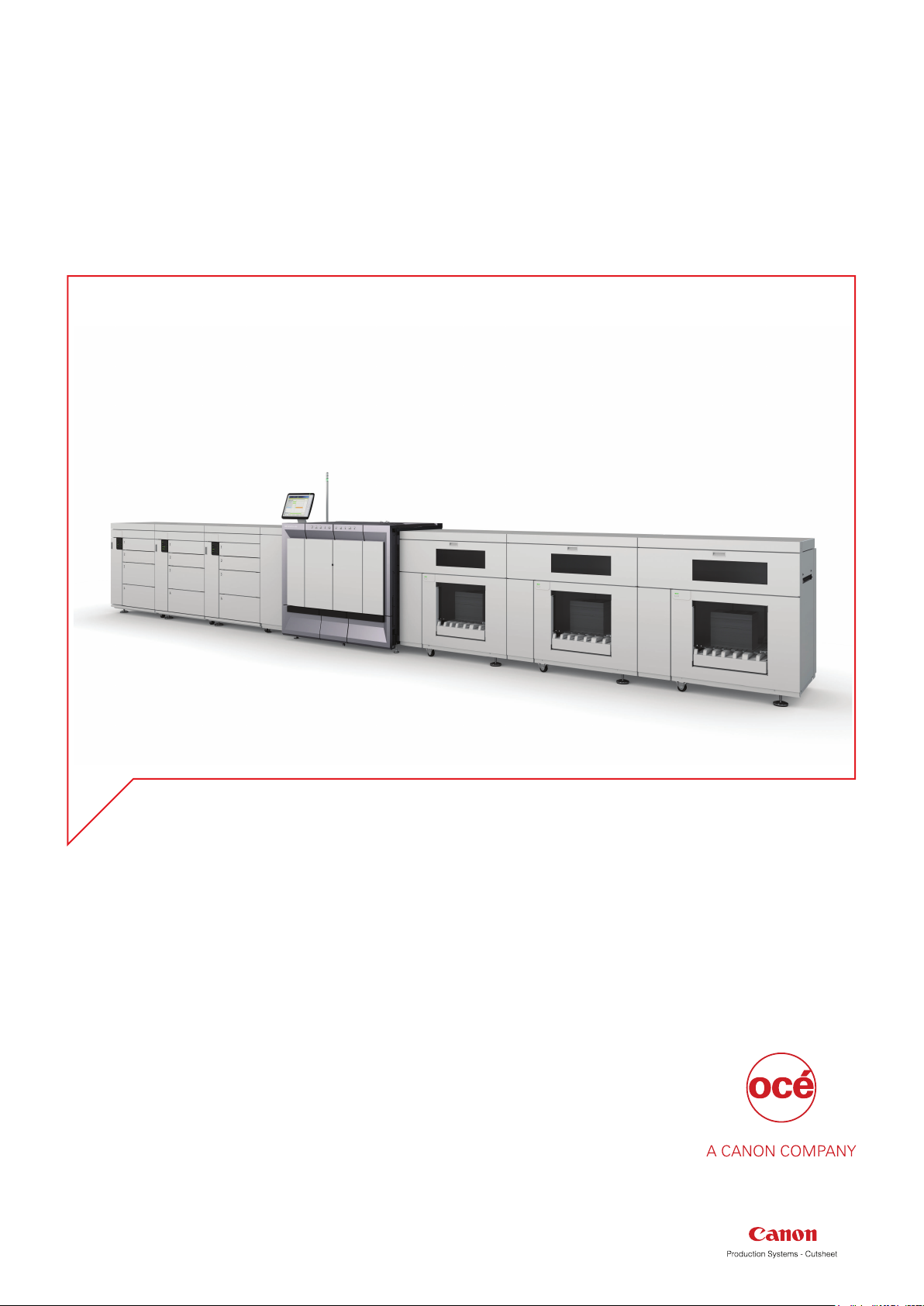
Maintenance guide
Océ VarioPrint® 6000 line
VarioPrint 6180, 6220, 6270, 6330
Page 2

Copyright and Trademarks
Copyright
Copyright 2006-2017 Océ.
Illustrations and specifications do not necessarily apply to products and services offered in each
local market. No part of this publication may be reproduced, copied, adapted or transmitted,
transcribed, stored in a retrieval system, or translated into any language or computer language in
any form or by any means, electronic, mechanical, optical, chemical, manual, or otherwise,
without the prior written permission of Océ.
OCÉ MAKES NO WARRANTY OF ANY KIND WITH REGARD TO THE CONTENTS OF THIS
PUBLICATION, EITHER EXPRESS OR IMPLIED, EXCEPT AS PROVIDED HEREIN, INCLUDING
WITHOUT LIMITATION, THEREOF, WARRANTIES AS TO MARKETABILITY, MERCHANTABILITY,
FITNESS FOR A PARTICULAR PURPOSE OF USE OR NON-INFRINGEMENT. OCÉ SHALL NOT BE
LIABLE FOR ANY DIRECT, INCIDENTAL, OR CONSEQUENTIAL DAMAGES OF ANY NATURE, OR
LOSSES OR EXPENSES RESULTING FROM THE USE OF THE CONTENTS OF THIS PUBLICATION.
Océ reserves the right to revise this publication and to make changes from time to time in the
content hereof without obligation to notify any person of such revision or changes.
Language
Translation of the original instructions that are in British English.
Trademarks
Océ, Océ VarioPrint are registered trademarks of Océ-Technologies B.V. Océ is a Canon company.
All other trademarks are the property of their respective owners.
Edition 2017-07
Software version 7.1
US
Page 3

Contents
Contents
Chapter 1
Introduction.........................................................................................................................5
Notes for the reader......................................................................................................................................... 6
Available documentation.................................................................................................................................8
Introduction to the maintenance tasks........................................................................................................... 9
Determine the required maintenance...........................................................................................................12
Chapter 2
Maintenance tasks - Level 1.............................................................................................13
Replace the cleaners...................................................................................................................................... 14
Open the doors and covers.....................................................................................................................14
Unlock the clean units............................................................................................................................. 17
Lift the clean units....................................................................................................................................18
Remove the sheet cleaners..................................................................................................................... 19
Remove the spiral cleaners.....................................................................................................................21
Recondition the sheet cleaners...............................................................................................................23
Install the spiral cleaners.........................................................................................................................24
Install the sheet cleaners.........................................................................................................................25
Lower the clean units...............................................................................................................................26
Lock the clean units................................................................................................................................. 27
Close the covers.......................................................................................................................................28
Clean the frame unit................................................................................................................................ 30
Finish the maintenance task....................................................................................................................33
Lock the clean unit (left).................................................................................................................................34
Lock the clean unit (right).............................................................................................................................. 36
Chapter 3
Maintenance tasks - Level 2.............................................................................................39
Remove sheets from the process modules..................................................................................................40
Remove sheets from the interface module............................................................................................40
Open the doors.........................................................................................................................................41
Remove sheets at the top cover............................................................................................................. 42
Remove sheets at the inner covers........................................................................................................ 43
Remove sheets from the registration unit............................................................................................. 46
Remove the preheat unit.........................................................................................................................48
Disassemble and assemble the preheat unit.........................................................................................50
Install the preheat unit.............................................................................................................................52
Unlock the clean units............................................................................................................................. 54
Lift the clean units....................................................................................................................................55
Lower the clean units...............................................................................................................................56
Lock the clean units................................................................................................................................. 57
Close the covers.......................................................................................................................................58
Finish the maintenance task....................................................................................................................60
Clean the OPC belt (left).................................................................................................................................61
Open the doors.........................................................................................................................................61
Unlock the OPC unit (left)........................................................................................................................62
Clean the OPC belt (left).......................................................................................................................... 63
Lock the OPC unit (left)............................................................................................................................65
Finish the maintenance task....................................................................................................................66
Océ VarioPrint 6000 line
3
Page 4

Contents
Clean the OPC belt (right).............................................................................................................................. 67
Open the doors.........................................................................................................................................67
Unlock the OPC unit (right)..................................................................................................................... 68
Clean the OPC belt (right)........................................................................................................................69
Lock the OPC unit (right)......................................................................................................................... 71
Finish the maintenance task....................................................................................................................72
Clean the glue cleaning rollers......................................................................................................................73
Open the doors and covers.....................................................................................................................73
Unlock the clean units............................................................................................................................. 76
Lift the clean units....................................................................................................................................77
Lift the TTF units...................................................................................................................................... 78
Prepare for cleaning.................................................................................................................................80
Clean the glue cleaning rollers............................................................................................................... 81
Close the TTF units.................................................................................................................................. 82
Lower the clean units...............................................................................................................................85
Lock the clean units................................................................................................................................. 86
Close the covers.......................................................................................................................................87
Finish the maintenance task....................................................................................................................89
Chapter 4
Optional light-weight media module..............................................................................91
Check the filter................................................................................................................................................92
Replace the filter.............................................................................................................................................93
Remove the air guidance unit....................................................................................................................... 95
Install the air guidance unit........................................................................................................................... 97
Index...................................................................................................................................99
4
Océ VarioPrint 6000 line
Page 5

Chapter 1
Introduction
Page 6
Notes for the reader
Notes for the reader
Typography
This manual uses the following typography to indicate elements that are part of the user
interface.
Typography Indicates
[Text between square brackets] Name of a button, tile, setting, value, or other
<Text between angle brackets> • Name of a key on a keyboard
option of the user interface
• Name of a variable: item that varies according to the context
Text displayed in courier font
[Text]→[displayed in]→[menucascade] Names of options to be used in a fixed order
Safety symbols
Before you use this product, make sure you read and understand the safety information that
belongs to the product. Find the safety information on
follow all warnings and instructions marked on the product.
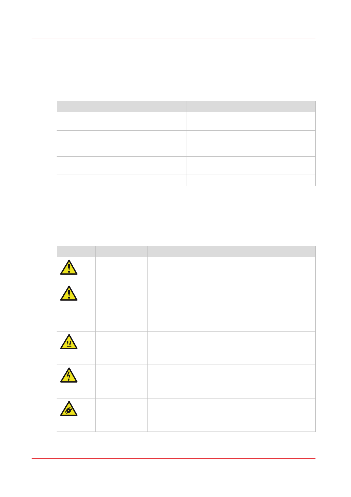
This manual uses the following safety symbols to indicate hazards and precautions.
Symbol Type of symbol Indicates
WARNING
CAUTION
• File path
• Command Prompt comment
http://downloads.oce.com
Indicates a warning concerning operations that may lead to
death or injury to persons if not performed correctly. To use
the machine safely, always pay attention to these warnings.
Indicates a caution concerning operations that may lead to injury to persons if not performed correctly. To use the machine safely, always pay attention to these cautions.
This indication can concern hazards that have a specific CAUTION symbol. The 'hot surface', 'electric shock', 'moving
parts' and 'laser beam' cautions are listed below.
. Also be sure to
Chapter 1 - Introduction
6
CAUTION Hot surface
Indicates a caution concerning operations that may lead to injury to persons if not performed correctly. To use the machine safely, always pay attention to these cautions.
CAUTION Electric shock
Indicates a caution concerning operations that may lead to injury to persons if not performed correctly. To use the machine safely, always pay attention to these cautions.
CAUTION Moving parts
Indicates a caution concerning operations that may lead to injury to persons if not performed correctly. To use the machine safely, always pay attention to these cautions.
4
Océ VarioPrint 6000 line
Page 7
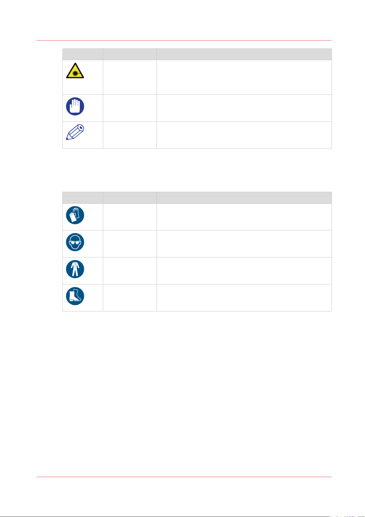
Symbol Type of symbol Indicates
CAUTION Laser beam
Indicates a caution concerning operations that may lead to injury to persons if not performed correctly. To use the machine safely, always pay attention to these cautions.
Notes for the reader
IMPORTANT
NOTE
Body protection symbols
This manual uses the following body protection symbols to indicate that it is important to protect
yourself before performing a specific task or action.
Symbol Type of symbol Indicates
IMPORTANT Hand protection
IMPORTANT Eye protection
IMPORTANT Body protection
Indicates operational requirements and restrictions. Be sure
to read these items carefully to operate the machine correctly
and to avoid damaging the machine or property.
Indicates a clarification of an operation or contains additional
explanations for a procedure. Reading these notes is highly
recommended.
Wear the mentioned type of gloves when you perform this
task or action.
Use the mentioned type of eye protection when you perform
this task or action.
Wear the mentioned type of body protection when you perform this task or action.
IMPORTANT Foot protection
Wear the mentioned type of safety footwear when you perform this task or action.
Océ VarioPrint 6000 line
Chapter 1 - Introduction
7
Page 8

Available documentation
Available documentation
Introduction
This machine is delivered with the following items:
• A 'Documentation and Driver Notice'
• A 'Safety Information Sheet'.
Main Content of the User Manuals
NOTE
Please check downloads.oce.com for the latest version of the documentation.
The following table provides an overview of the main content of the user manuals.
User Manual Main content
User Manual • Overview of the main system components
• Work with the control panel
• Handle and manage the jobs on the control panel
• Optional finishers and other devices
• Add media, toner and staples
Maintenance tasks • Replacing parts
• Cleaning parts
• Solve a paper jam in the engine module
Extended key operator
maintenance guide
Safety Information • Instructions for Safe Use
• TTF maintenance
• OPC maintenance
• Registration adjustment
• Optional light-weight media module
Chapter 1 - Introduction
8
Océ VarioPrint 6000 line
Page 9
Introduction to the maintenance tasks
Introduction
This manual is intended for trained and certified operators who received the special maintenance
training for the printer. Therefore, this manual is only intended as a reference guide for the
described maintenance procedures.
On the control panel, you must always press [Next] to continue with the next step, or [Finish] to
complete a maintenance task. After you finished a maintenance task, the control panel will also
ask you to restart the system. The procedures in this manual only describe the physical
maintenance actions.
NOTE
In this manual and on the control panel, the trained and certified operator is referred to as the
key operator.
NOTE
Only a key operator is allowed to perform the maintenance tasks that are described in this
manual. You need to have access rights to perform maintenance tasks. A maintenance session
can involve more than 1 maintenance task. A maintenance session ends when you leave the
maintenance screen that displays the maintenance tasks.
Introduction to the maintenance tasks
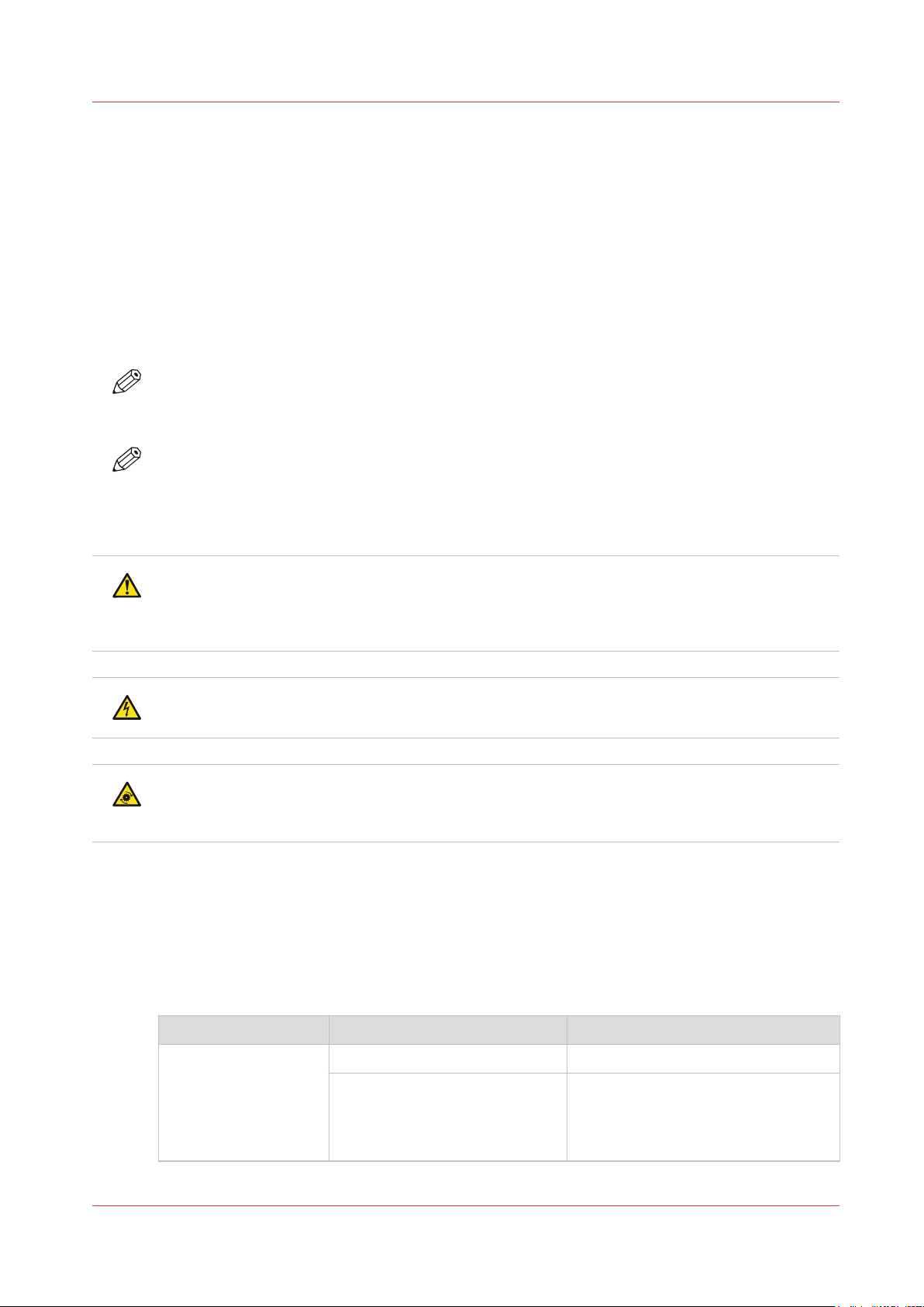
CAUTION
The key operator executes the maintenance tasks inside the machine. The key operator must be
aware of the risks of working inside the machine. The key operator must be trained to execute
the described maintenance actions before the key operator can execute these actions.
CAUTION
When you do not follow the procedures as described, there is a risk of electrical shock.
CAUTION
When you do not follow the procedures as described, there is a risk of injury because of moving
parts.
The maintenance levels
The machine is a high-volume production printer. Therefore, a short downtime due to required
maintenance is very important to you. To help you reduce the downtime, 2 levels of maintenance
tasks which key operators can carry out are defined. The following table gives an overview of the
maintenance levels and the respective maintenance tasks.
Overview of the maintenance tasks
Maintenance level
Maintenance task Where to find more information
1 Replace the cleaners
Océ VarioPrint 6000 line
Lock the clean units •
Replace the cleaners
on page 14
Lock the clean unit (left)
page 34
•
Lock the clean unit (right)
page 36
Chapter 1 - Introduction
on
on
4
9
Page 10
Introduction to the maintenance tasks
Maintenance level Maintenance task Where to find more information
2 Solve paper jams in hot areas of
the printer
Clean the OPC belts •
Clean the glue cleaning rollers
Optional light-weight media module
To print light-weight media the optional light-weight media module must be installed. The
maintenance actions for the light-weight media module are:
• Check the filter:
• Replace the filter:
Check the filter
Replace the filter
• Remove the air guidance unit to access the TTF:
• Install the air guidance unit:
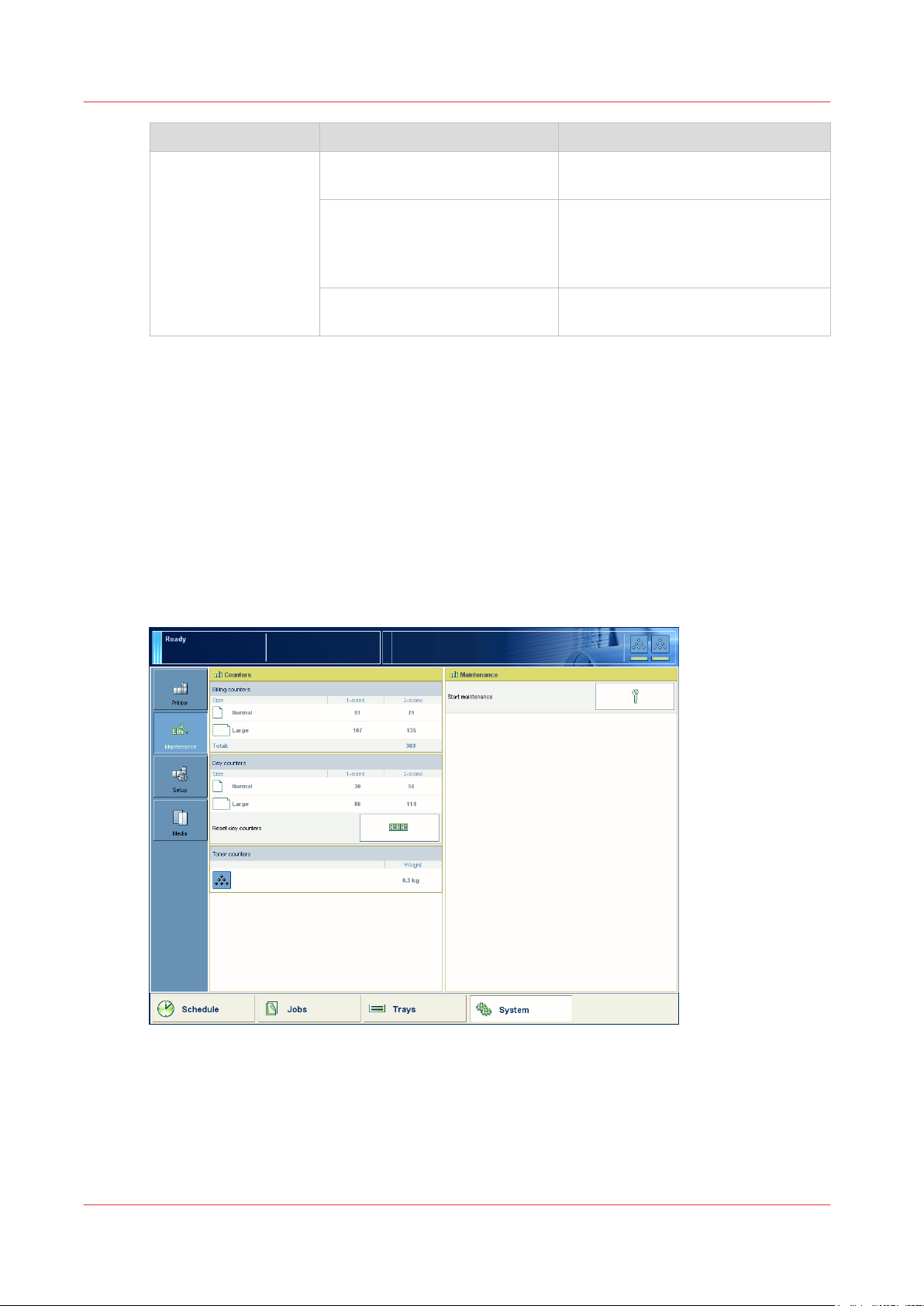
Begin maintenance
The maintenance section of the [System] view shows the required or suggested maintenance
tasks. Here, you can only view the maintenance tasks.
on page 92
on page 93.
Remove the air guidance unit
Install the air guidance unit
Remove sheets from the process
modules
on page 40
Clean the OPC belt (left)
on
page 61)
•
Clean the OPC belt (right)
on
page 67)
Clean the glue cleaning rollers
page 73
on page 95.
on page 97.
on
[1] Begin maintenance
When you press the [Start maintenance] button, the actual maintenance screen appears.
The maintenance screen
After you press the [Start maintenance] button in the [System] view, the maintenance screen
appears. The maintenance screen shows the required and suggested maintenance tasks. A red
Chapter 1 - Introduction
10
Océ VarioPrint 6000 line
Page 11

Introduction to the maintenance tasks
icon indicates required tasks. An orange icon indicates suggested tasks. These tasks may be
required soon. You can select a maintenance task from the list and press [Start] to start the
maintenance wizard.
Océ VarioPrint 6000 line
Chapter 1 - Introduction
11
Page 12

Determine the required maintenance
Determine the required maintenance
Introduction
The operator panel indicates that maintenance is required, and when maintenance is required.
The operator panel also leads you through all the steps of each maintenance task. This section
describes how the operator panel indicates that the machine requires maintenance.
Replace the cleaners
The sheet cleaners and the spiral cleaners are consumables. The cleaners have counters. If
maintenance is required immediately or soon, the color of the maintenance icon changes.
The [Maintenance] section of the [System] view on the operator panel indicates that you can or
must replace the cleaners. There, the counter information is regularly updated.
The following table describes what you must do when the maintenance icon is blue, orange or
red.
When to replace the cleaners
Maintenance icon Description
The maintenance icon is blue. Maintenance is currently not required.
The maintenance icon is orange. The machine can print another 20,000
images before you must replace the cleaners. Your service technician
can change this to another number within the range of 10,000 and
50,000.
The maintenance icon is red. The counter is 0. The machine stops. You
must replace the cleaners. Only then, the machine can continue printing.
Solve a paper jam in hot areas of the machine
When a paper jam occurs in the hot areas of the machine, the procedure is as follows.
• The machine stops.
• The operator panel displays the maintenance screen with this maintenance task.
• Select the maintenance task and press [Start].
• If applicable, enter the maintenance PIN.
• Follow the instructions on the operator panel to solve the paper jam.
Chapter 1 - Introduction
12
Océ VarioPrint 6000 line
Page 13

Chapter 2
Maintenance tasks - Level 1
Page 14

Replace the cleaners
Replace the cleaners
Open the doors and covers
Introduction
This procedure is only intended for key operators who received the special maintenance training.
When to do
If the maintenance icon in the dashboard indicates that maintenance is required soon or
immediately.
Before you begin
Make sure that you have 2 new spiral cleaners and 2 new sheet cleaners at hand.
Service key (supplied with the machine)
Socket wrench 10 (supplied with the machine)
Heat-resistant gloves (supplied with the machine)
Adhesive tape (supplied with the machine)
CAUTION
Certain parts of the machine may be hot. Therefore, always use the special heat- and oilresistant fuser gloves.
Procedure
Select the maintenance task from the list of the required and suggested maintenance tasks.
1.
[System] view -> maintenance section -> press the [Start maintenance] button.
Press [Start] to start the maintenance wizard.
2.
At the start of the procedure, the machine is turned off.
Use socket wrench 10 to loosen the bolt of the front doors (2).
3.
CAUTION
Wait until the machine is turned off. Opening the doors too soon can possibly cause
injury.
Chapter 2 - Maintenance tasks - Level 1
14
Océ VarioPrint 6000 line
Page 15
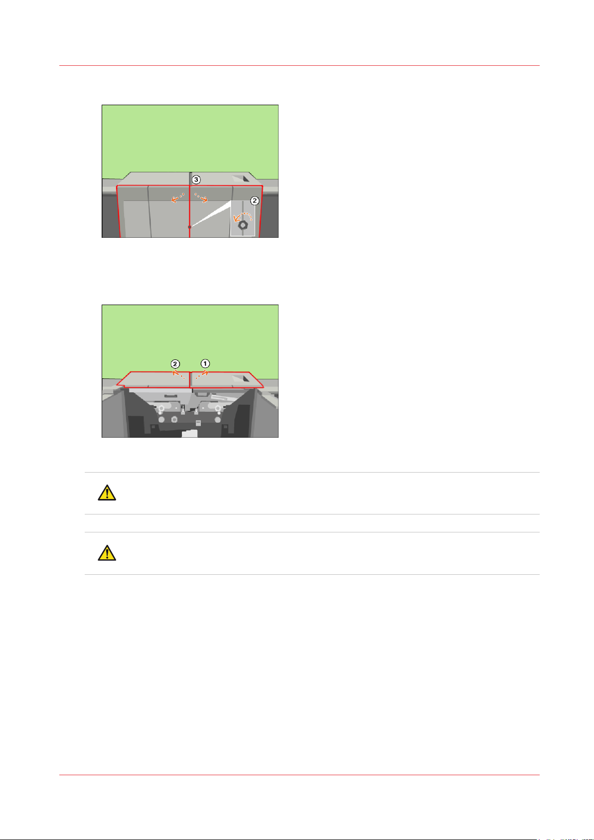
Open the lower door. Open the front doors (3).
4.
[2] Open the front doors
Lift the right-hand top cover to the upper position (1).
5.
Lift the left-hand top cover to the upper position (2).
6.
Open the doors and covers
[3] Lift the top covers
CAUTION
Hot area. Use heat-resistant gloves.
CAUTION
Make sure that the left-hand inner cover is locked in the upper position.
Unlock the left-hand upper cover and lift the left-hand inner cover to the upper position (1).
7.
Océ VarioPrint 6000 line
Chapter 2 - Maintenance tasks - Level 1
15
Page 16
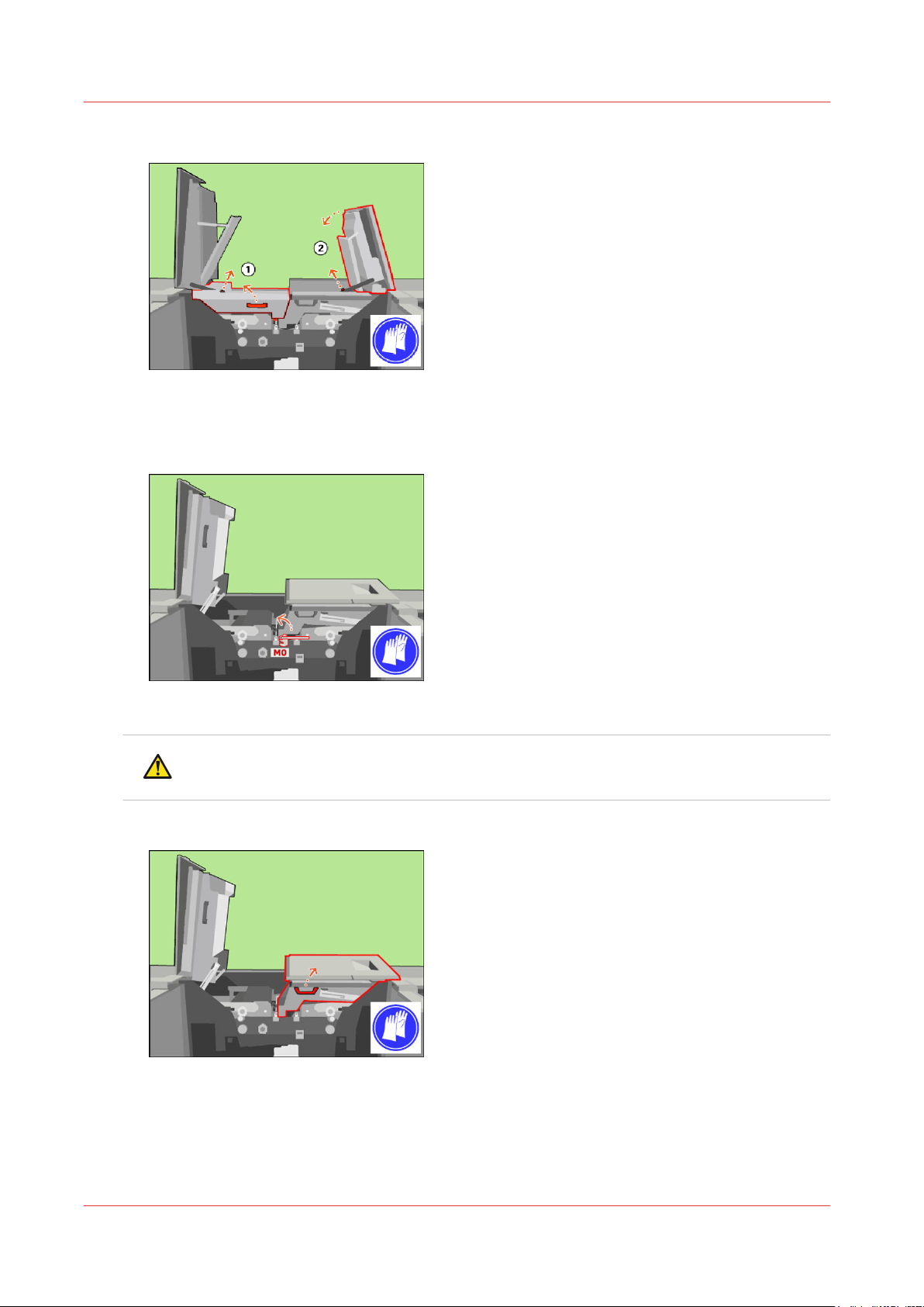
Open the doors and covers
Unlock and lower the right-hand top cover (2).
8.
[4] Lift the left-hand inner cover
Only when the M0 lock is present, turn the M0 lock with the service key counter-clockwise to
9.
unlock the inner right-hand cover.
[5] When the M0 lock is present, unlock the inner right-hand cover
CAUTION
Make sure that the right-hand inner cover is locked in the upper position.
Lift the right-hand inner cover to the upper position.
10.
[6] Lift the right-hand inner cover
Chapter 2 - Maintenance tasks - Level 1
16
Océ VarioPrint 6000 line
Page 17
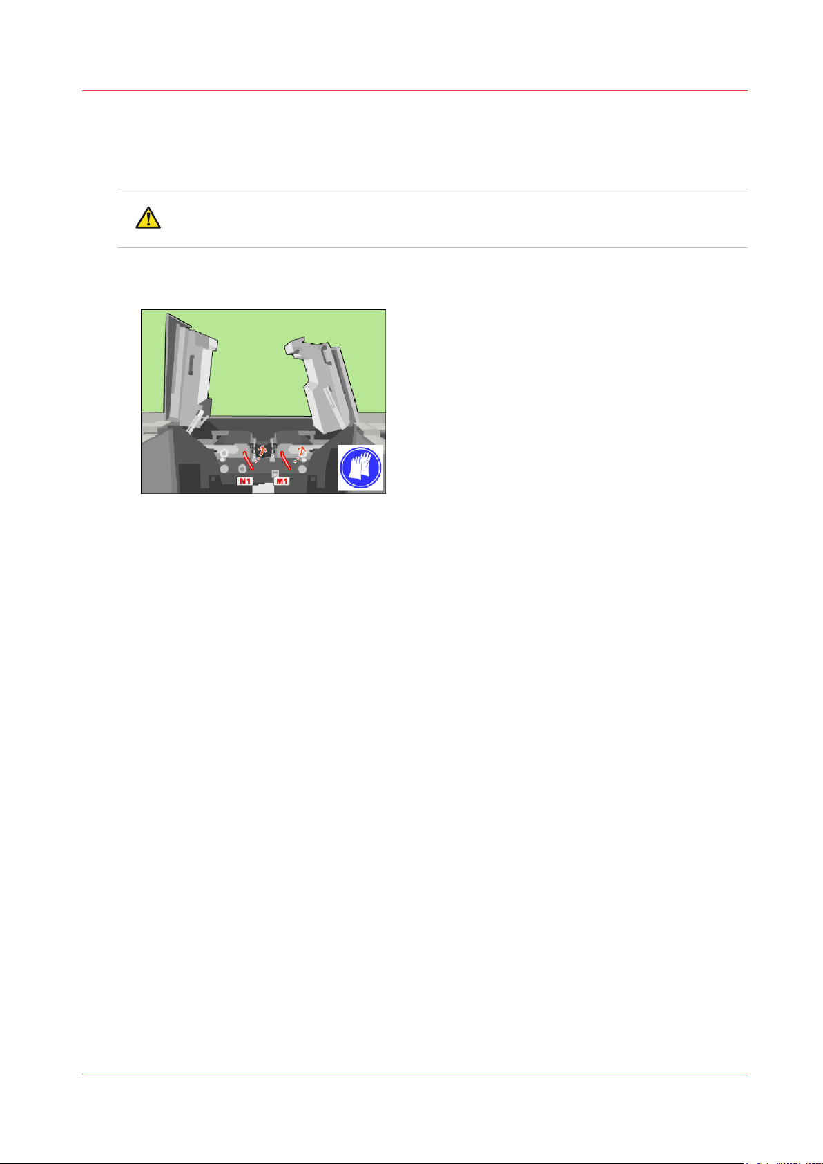
Unlock the clean units
Procedure
CAUTION
Hot area. Use heat-resistant gloves.
Use the service key to turn N1 counter-clockwise.
1.
Use the service key to turn M1 counter-clockwise.
2.
Unlock the clean units
[7] Unlock the clean units
Océ VarioPrint 6000 line
Chapter 2 - Maintenance tasks - Level 1
17
Page 18
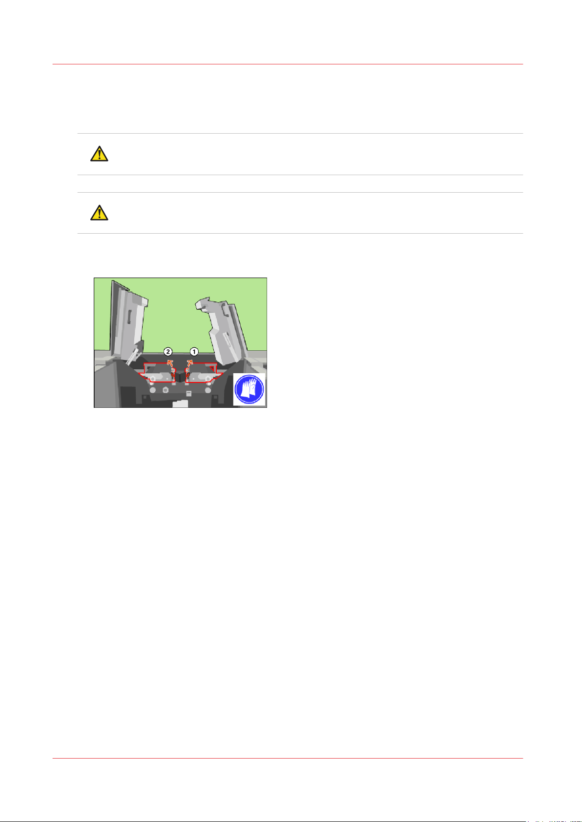
Lift the clean units
Lift the clean units
Procedure
CAUTION
Hot area. Use heat-resistant gloves.
CAUTION
Make sure that both clean units are locked in the upper position.
Use the red handle to lift the right-hand clean unit (1) to the upper position.
1.
Use the red handle to lift the left-hand clean unit (2) to the upper position.
2.
[8] Lift the clean units
Chapter 2 - Maintenance tasks - Level 1
18
Océ VarioPrint 6000 line
Page 19
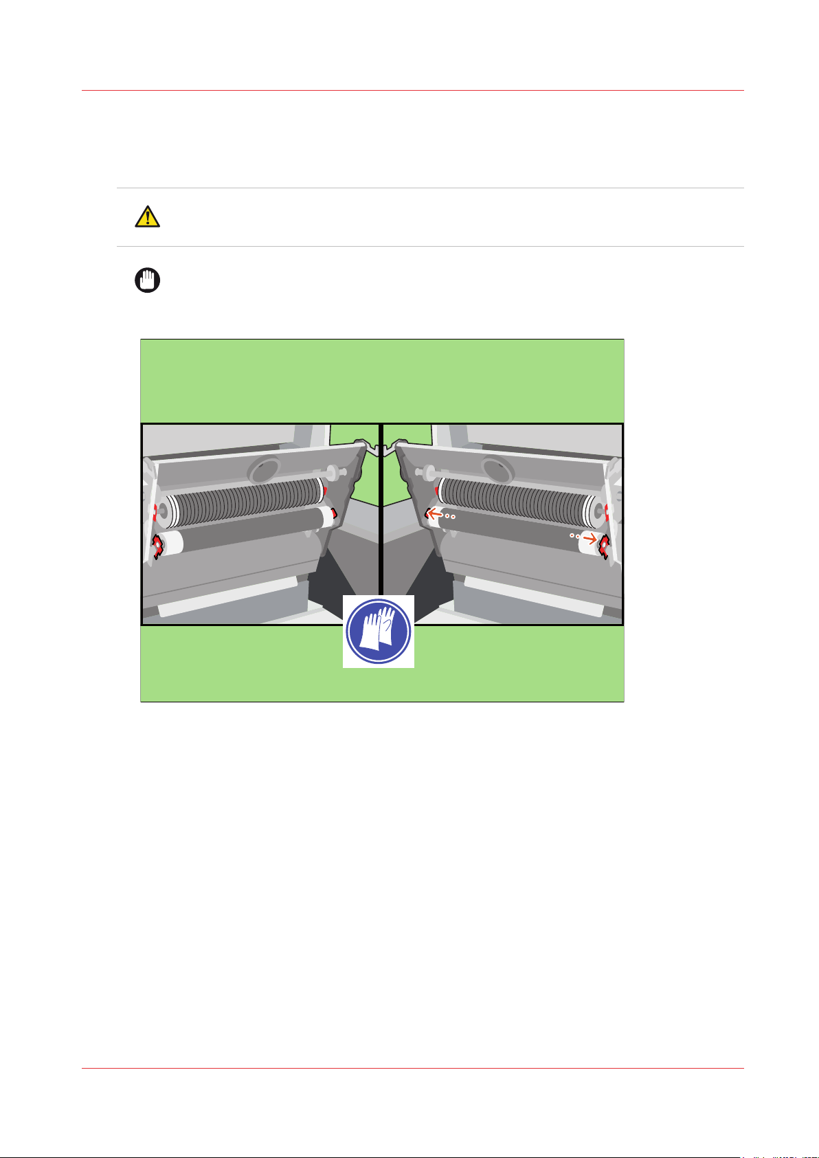
Remove the sheet cleaners
Procedure
CAUTION
Hot area. Use heat-resistant gloves.
IMPORTANT
Do not remove a layer of the sheet cleaner when the cleaner is inside the machine.
Press both red leaf springs at the end of the right-hand sheet cleaner outwards.
1.
Remove the sheet cleaners
[9] Press the red leaf springs outwards
Océ VarioPrint 6000 line
Chapter 2 - Maintenance tasks - Level 1
19
Page 20
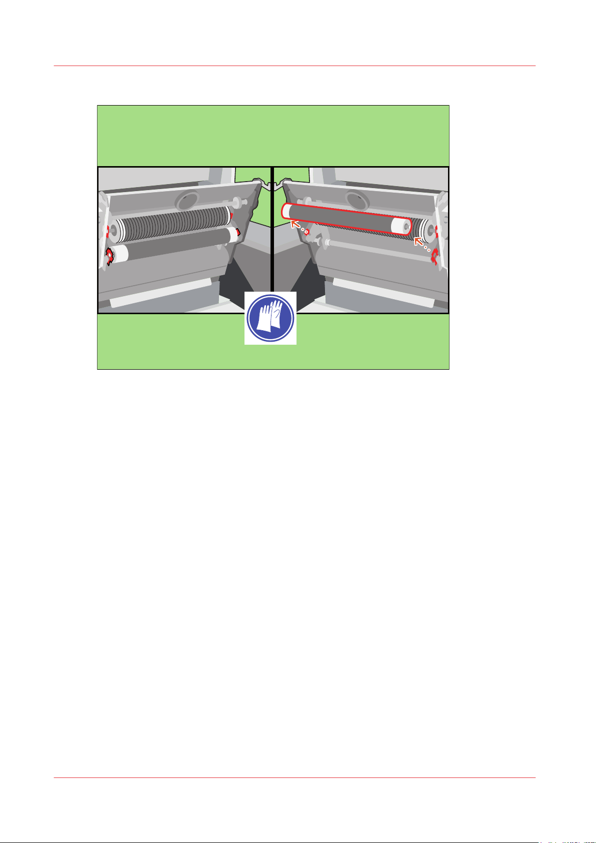
Remove the sheet cleaners
Remove the sheet cleaner.
2.
[10] Remove the sheet cleaners
Repeat the steps 1 and 2 for the left-hand sheet cleaner.
3.
Chapter 2 - Maintenance tasks - Level 1
20
Océ VarioPrint 6000 line
Page 21
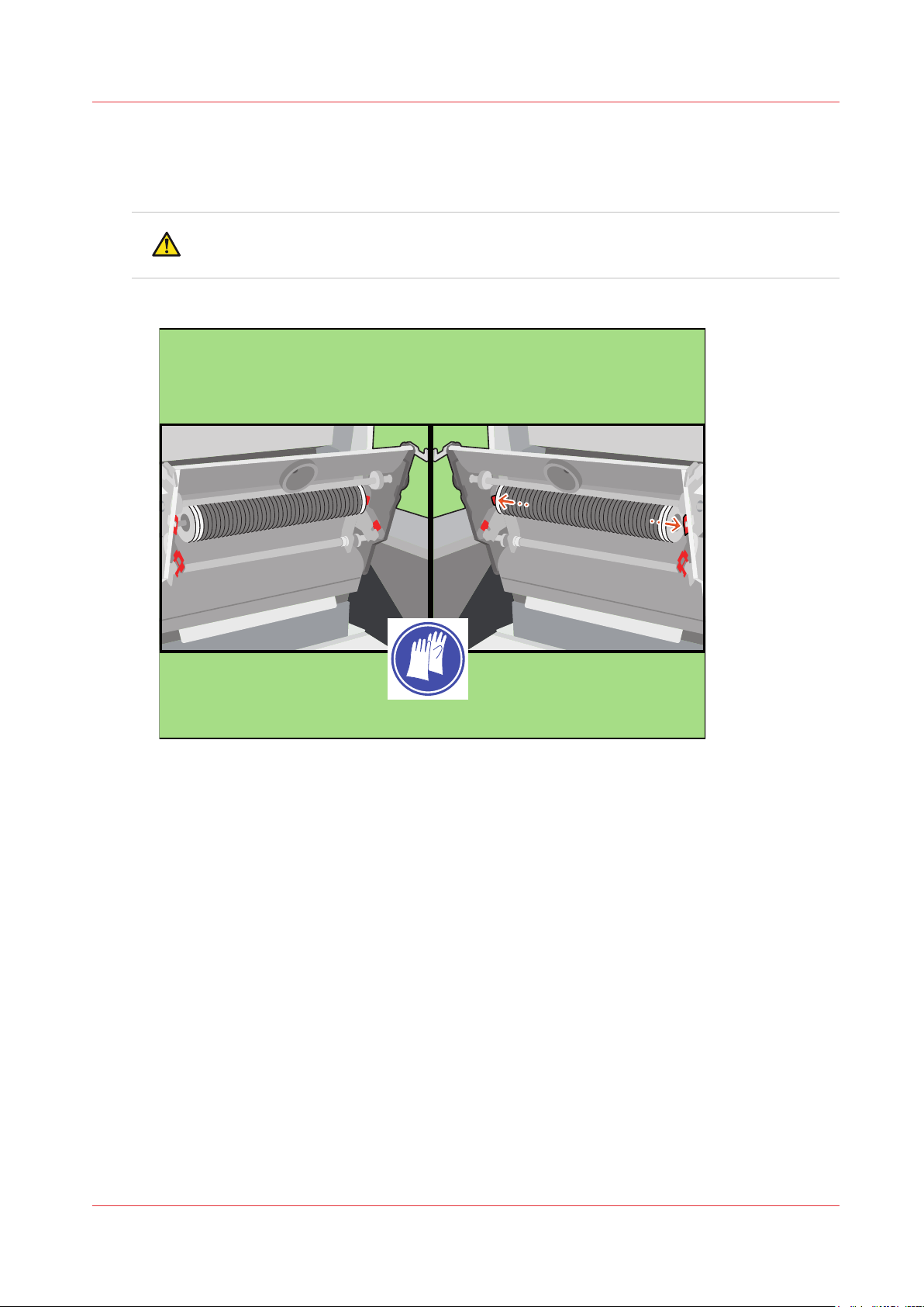
Remove the spiral cleaners
Procedure
CAUTION
Hot area. Use heat-resistant gloves.
Press both red leaf springs at the end of the right-hand spiral cleaner outwards.
1.
Remove the spiral cleaners
[11] Press the red leaf springs outwards
Océ VarioPrint 6000 line
Chapter 2 - Maintenance tasks - Level 1
21
Page 22
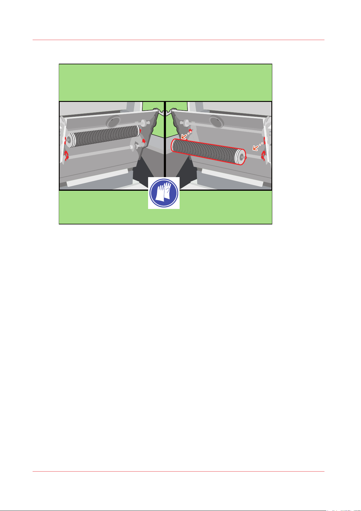
Remove the spiral cleaners
Remove the spiral cleaner.
2.
[12] Remove the spiral cleaners
Repeat the steps 1 and 2 for the left-hand spiral cleaner.
3.
Chapter 2 - Maintenance tasks - Level 1
22
Océ VarioPrint 6000 line
Page 23
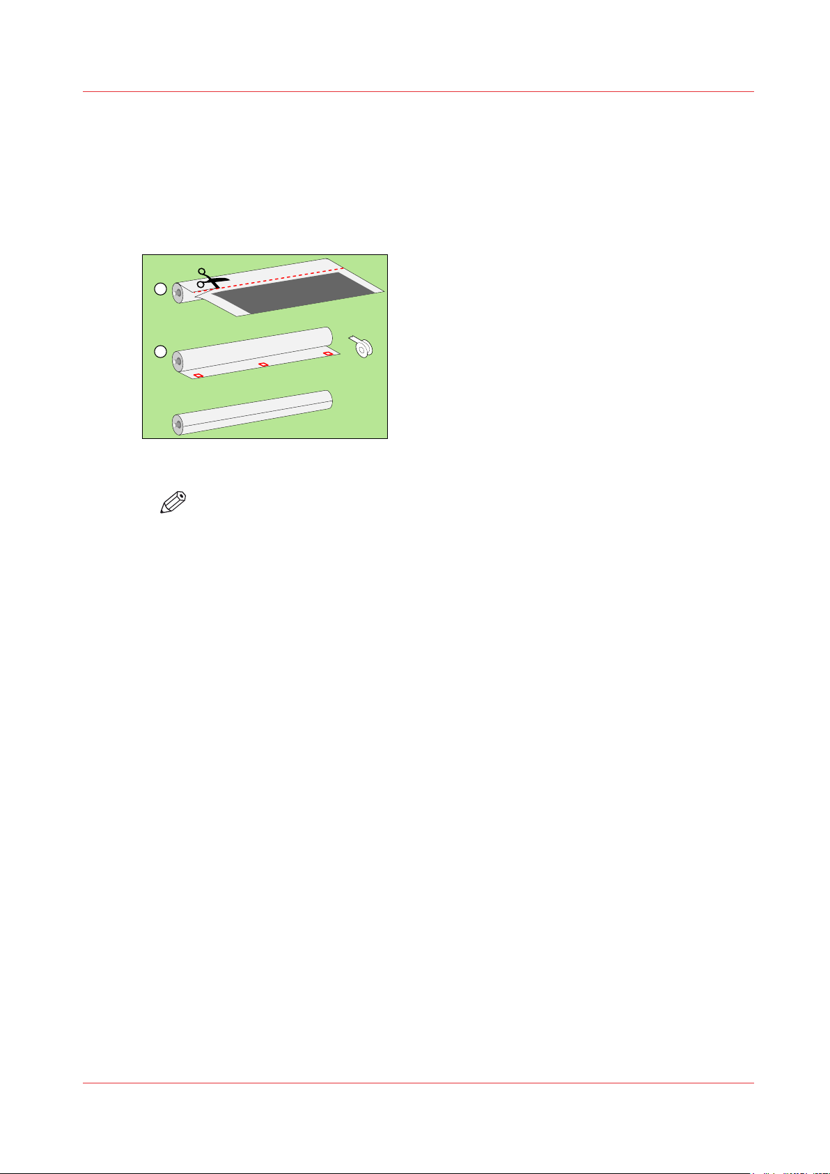
Recondition the sheet cleaners
1
2
Procedure
Remove 1 layer and an extra 2-3 cm (about 1 inch) of both sheet cleaners, including the old
1.
adhesive strip (1).
Use heat-resistant adhesive tape at 3 places to stick the end of the layer to the sheet cleaner (2).
2.
[13] Recondition the sheet cleaners
Recondition the sheet cleaners
NOTE
Only use a new sheet cleaner if the cylinder does not contain enough clean-sheet
paper.
Océ VarioPrint 6000 line
Chapter 2 - Maintenance tasks - Level 1
23
Page 24
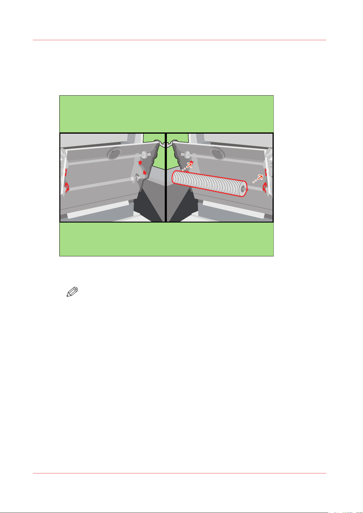
Install the spiral cleaners
Install the spiral cleaners
Procedure
Lock the right-hand spiral cleaner between the red leaf springs.
1.
[14] Install the spiral cleaners
Repeat step 1 for the left-hand spiral cleaner.
2.
NOTE
The spiral cleaners only fit in one way.
Chapter 2 - Maintenance tasks - Level 1
24
Océ VarioPrint 6000 line
Page 25
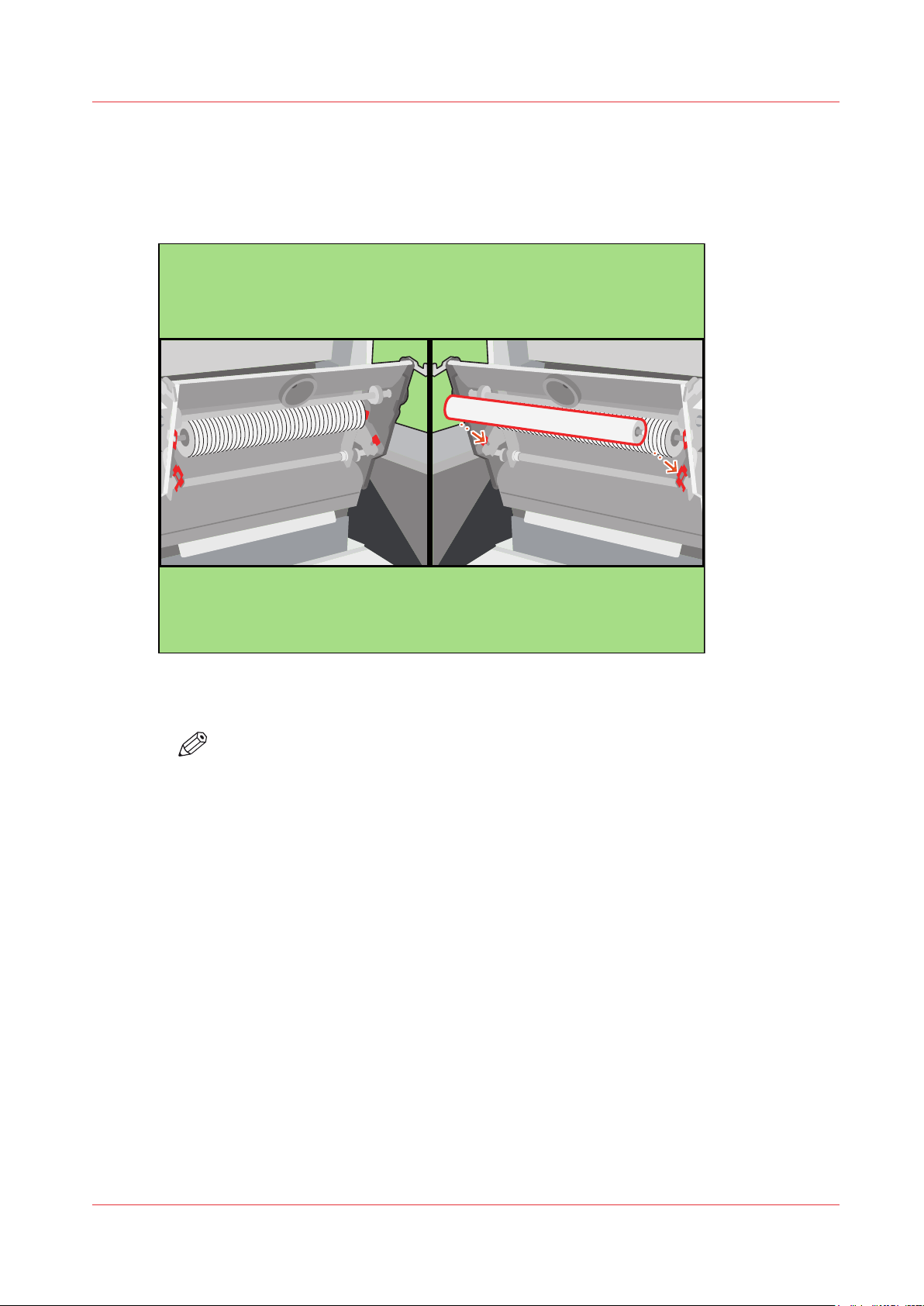
Install the sheet cleaners
Procedure
Lock the right-hand sheet cleaner between the red leaf springs.
1.
Install the sheet cleaners
[15] Install the sheet cleaners
Repeat step 1 for the left-hand sheet cleaner.
2.
NOTE
The sheet cleaners only fit in one way.
Océ VarioPrint 6000 line
Chapter 2 - Maintenance tasks - Level 1
25
Page 26
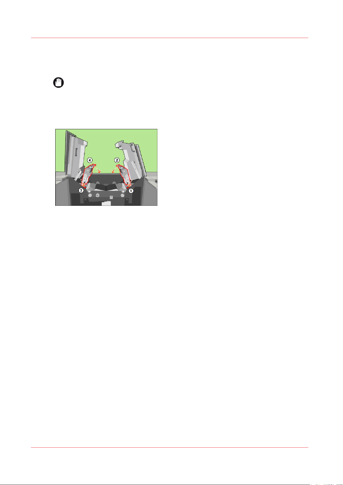
Lower the clean units
Lower the clean units
Procedure
IMPORTANT
Make sure that the clean units are in the lowest position.
Lift the right-hand clean unit and push the red handle to unlock the locking mechanism (1).
1.
Lower the right-hand clean unit into the locked position (2).
2.
Lift the left-hand clean unit and push the red handle to unlock the locking mechanism (3).
3.
Lower the left-hand clean unit into the locked position (4).
4.
[16] Lower the clean units
Chapter 2 - Maintenance tasks - Level 1
26
Océ VarioPrint 6000 line
Page 27
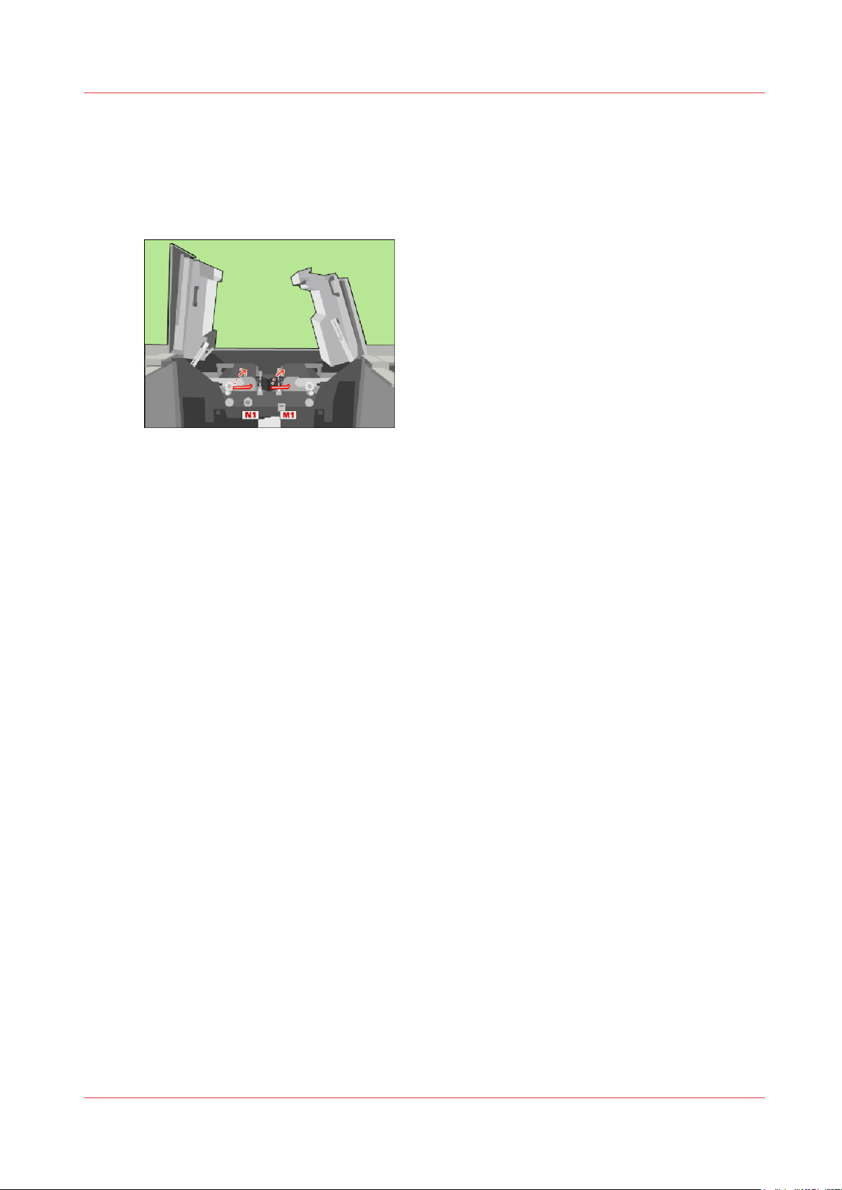
Lock the clean units
Procedure
Use the service key to turn N1 clockwise.
1.
Use the service key to turn M1 clockwise.
2.
[17] Lock the clean units
Lock the clean units
Océ VarioPrint 6000 line
Chapter 2 - Maintenance tasks - Level 1
27
Page 28
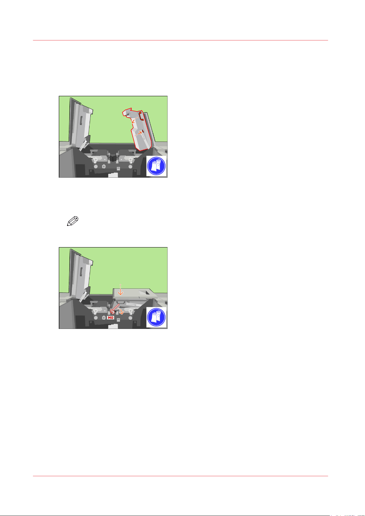
Close the covers
Close the covers
Procedure
Unlock and lower the right-hand inner cover.
1.
[18] Close the right-hand inner cover
Only when the M0 lock is present, push down the inner right-hand cover. Turn the M0 lock with
2.
the service key clockwise to lock the inner right-hand cover.
NOTE
Remove the service key.
[19] When the M0 lock is present, lock the inner right-hand cover
Lift the right-hand top cover to the upper position (1).
3.
Chapter 2 - Maintenance tasks - Level 1
28
Océ VarioPrint 6000 line
Page 29
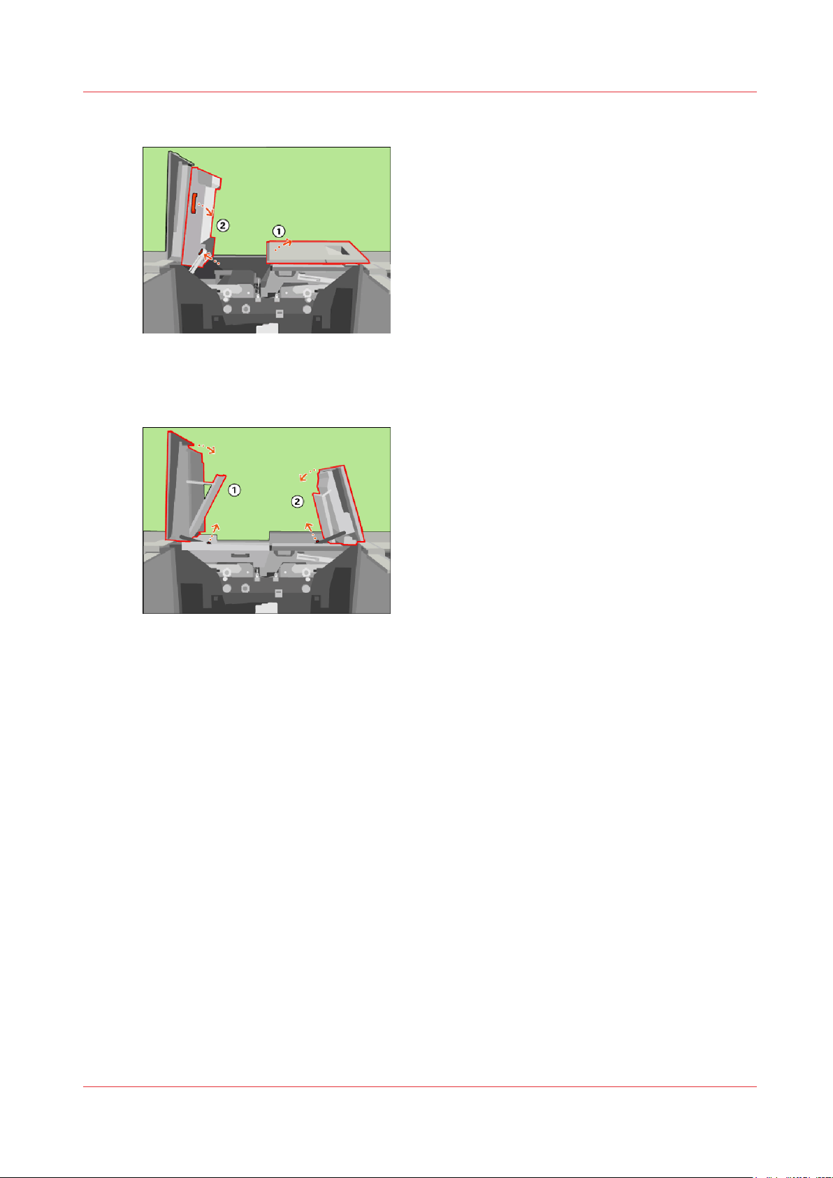
Unlock and lower the left-hand inner cover (2).
4.
[20] Close the left-hand inner cover
Close the left-hand top cover (1).
5.
Close the right-hand top cover (2).
6.
Close the covers
[21] Close the top covers
Océ VarioPrint 6000 line
Chapter 2 - Maintenance tasks - Level 1
29
Page 30
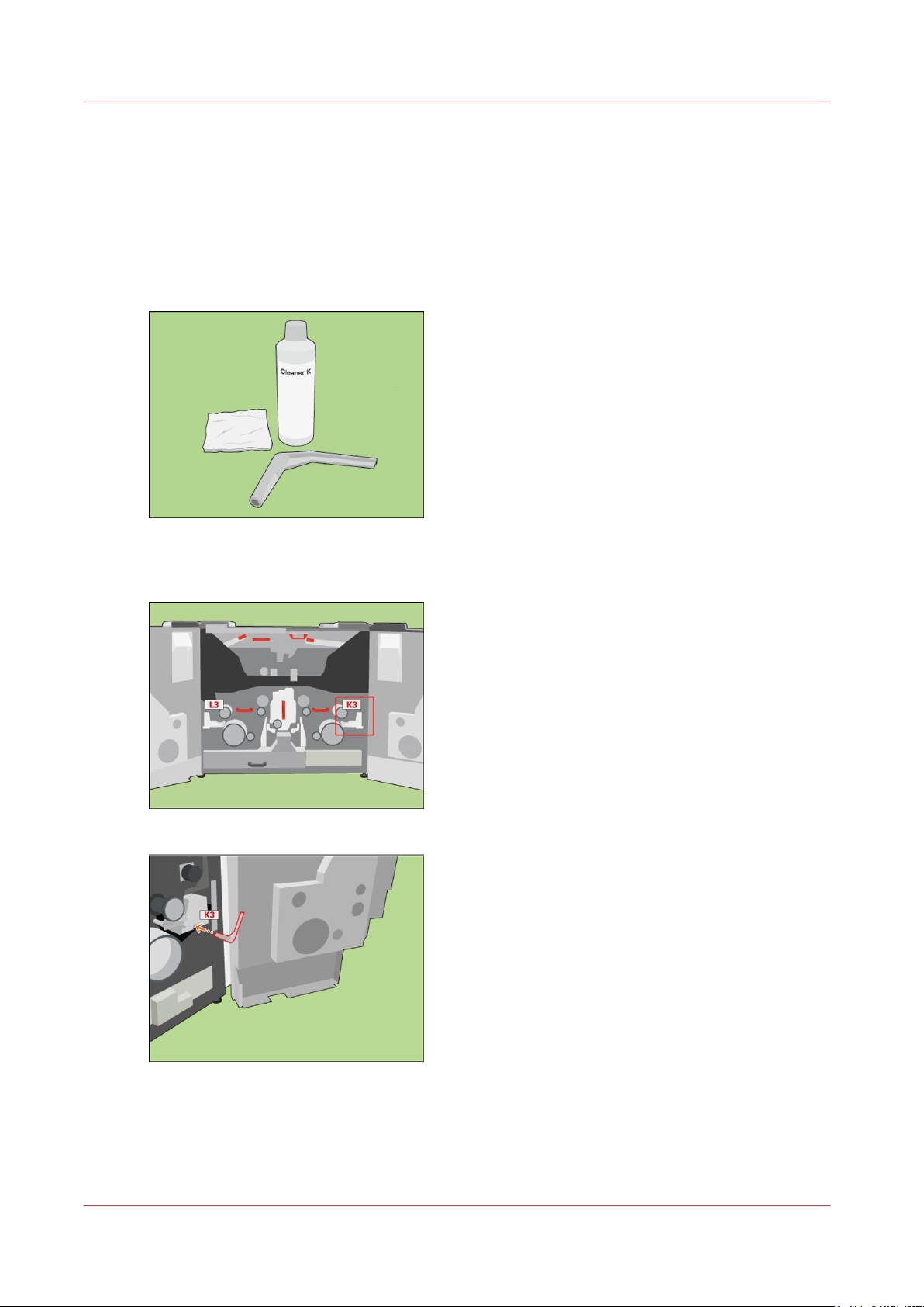
Clean the frame unit
Clean the frame unit
Procedure
Required tools and materials:
1.
• Cleaner K.
• D-wrench.
• Cleaning pad.
[22] Required tools and materials
Use a D-wrench to push and turn K3 clockwise.
2.
[24] Use a D-wrench to push K3.
Chapter 2 - Maintenance tasks - Level 1
30
Océ VarioPrint 6000 line
Page 31
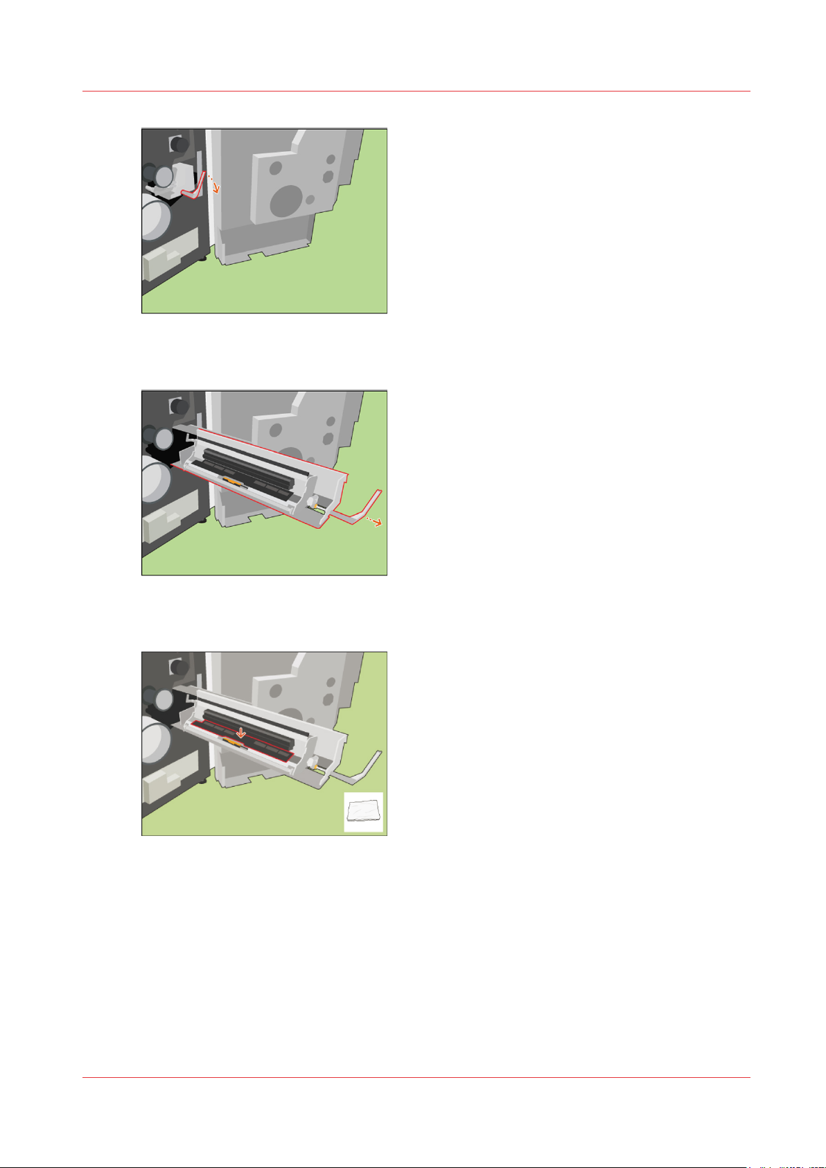
[25] Turn K3 clockwise
Move the frame unit outwards.
3.
Clean the frame unit
[26] Move the frame unit outwards.
Clean the frame unit with a cleaning pad.
4.
[27] Clean the frame unit with a cleaning pad
Océ VarioPrint 6000 line
Chapter 2 - Maintenance tasks - Level 1
31
Page 32
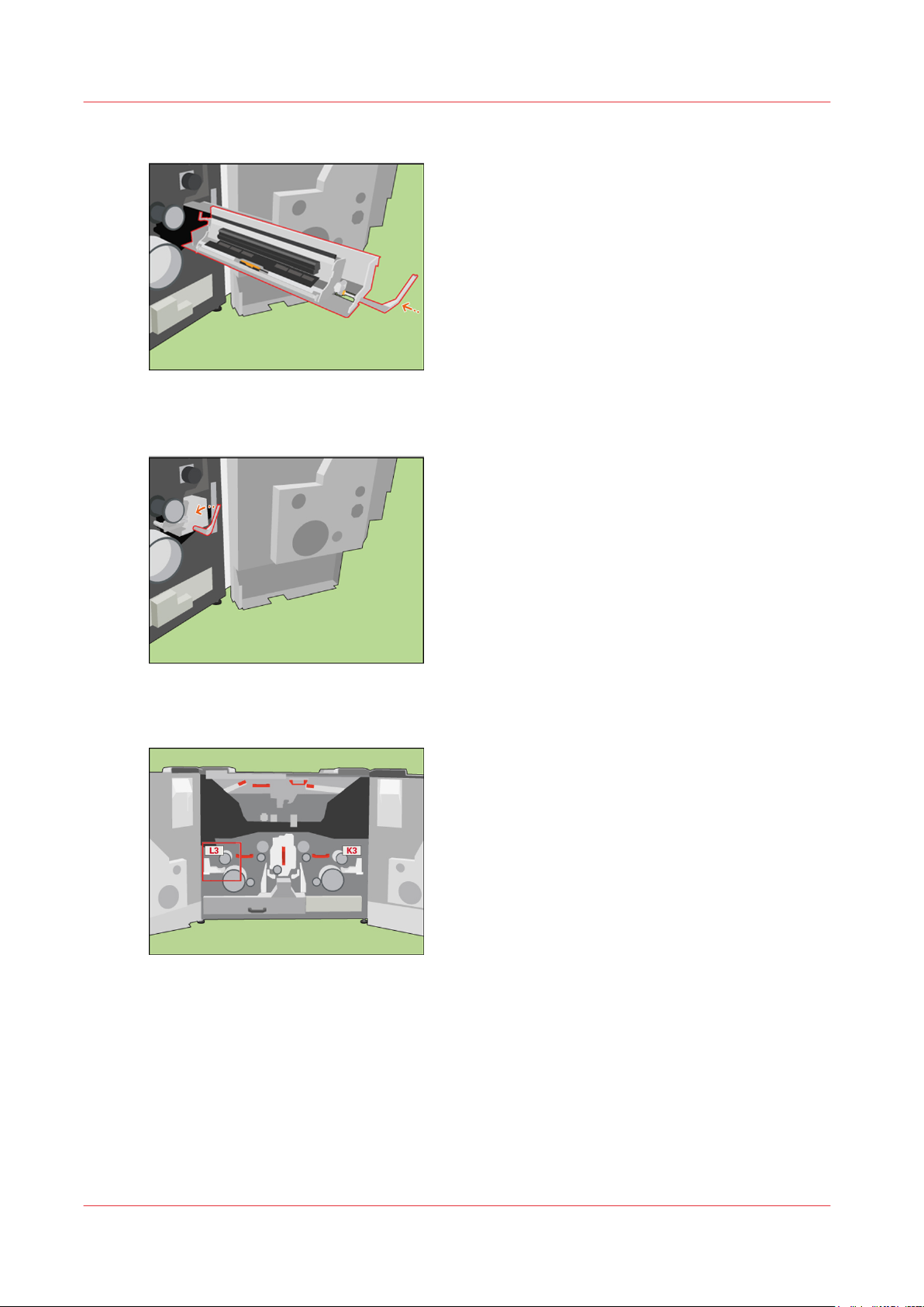
Clean the frame unit
Push the frame inwards.
5.
[28] Push the frame inwards
Use a D-wrench to push and turn K3 anticlockwise into the locked position.
6.
[29] Turn K3 counter-clockwise into the locked position
Repeat the steps 2 - 6 for the left-hand frame unit (L3).
7.
Chapter 2 - Maintenance tasks - Level 1
32
Océ VarioPrint 6000 line
Page 33
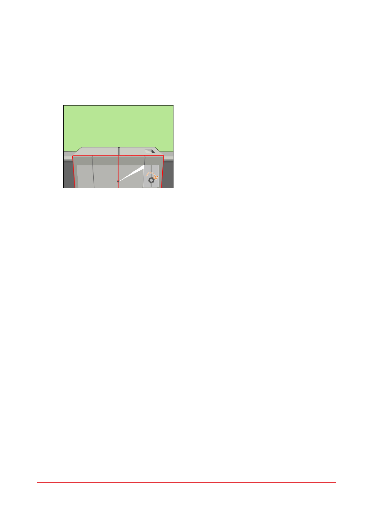
Finish the maintenance task
Procedure
Close the front doors.
1.
Use socket wrench 10 to tighten the bolt of the front doors.
2.
[31] Close the front doors
Close the lower door.
3.
On the operator panel, confirm that you successfully replaced the cleaners.
4.
Press [Stop] to close the maintenance screen. The machine is turned on.
5.
Finish the maintenance task
Océ VarioPrint 6000 line
Chapter 2 - Maintenance tasks - Level 1
33
Page 34
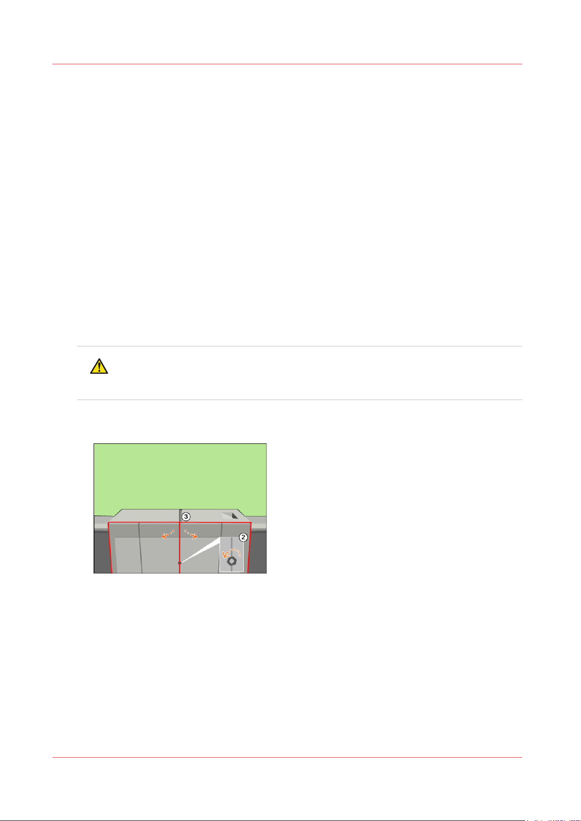
Lock the clean unit (left)
Lock the clean unit (left)
Introduction
This procedure is only intended for key operators who received the special maintenance training.
When to do
After you replaced the cleaners
you accidentally forgot to lock a clean unit after you replaced the cleaners, the machine will
detect this during the initialization. Then the operator panel will display this maintenance task.
Required tools
Service key (supplied with the machine)
Socket wrench 10 (supplied with the machine)
Procedure
Press [Start] to start the maintenance wizard.
1.
At the start of the procedure, the machine is turned off.
Use socket wrench 10 to loosen the bolt of the front doors (2).
2.
Open the front doors (3).
3.
Replace the cleaners
on page 14, you must restart the machine. If
CAUTION
Wait until the machine is turned off. Opening the doors too soon can possibly cause
injury.
[32] Open the front doors
Chapter 2 - Maintenance tasks - Level 1
34
Océ VarioPrint 6000 line
Page 35
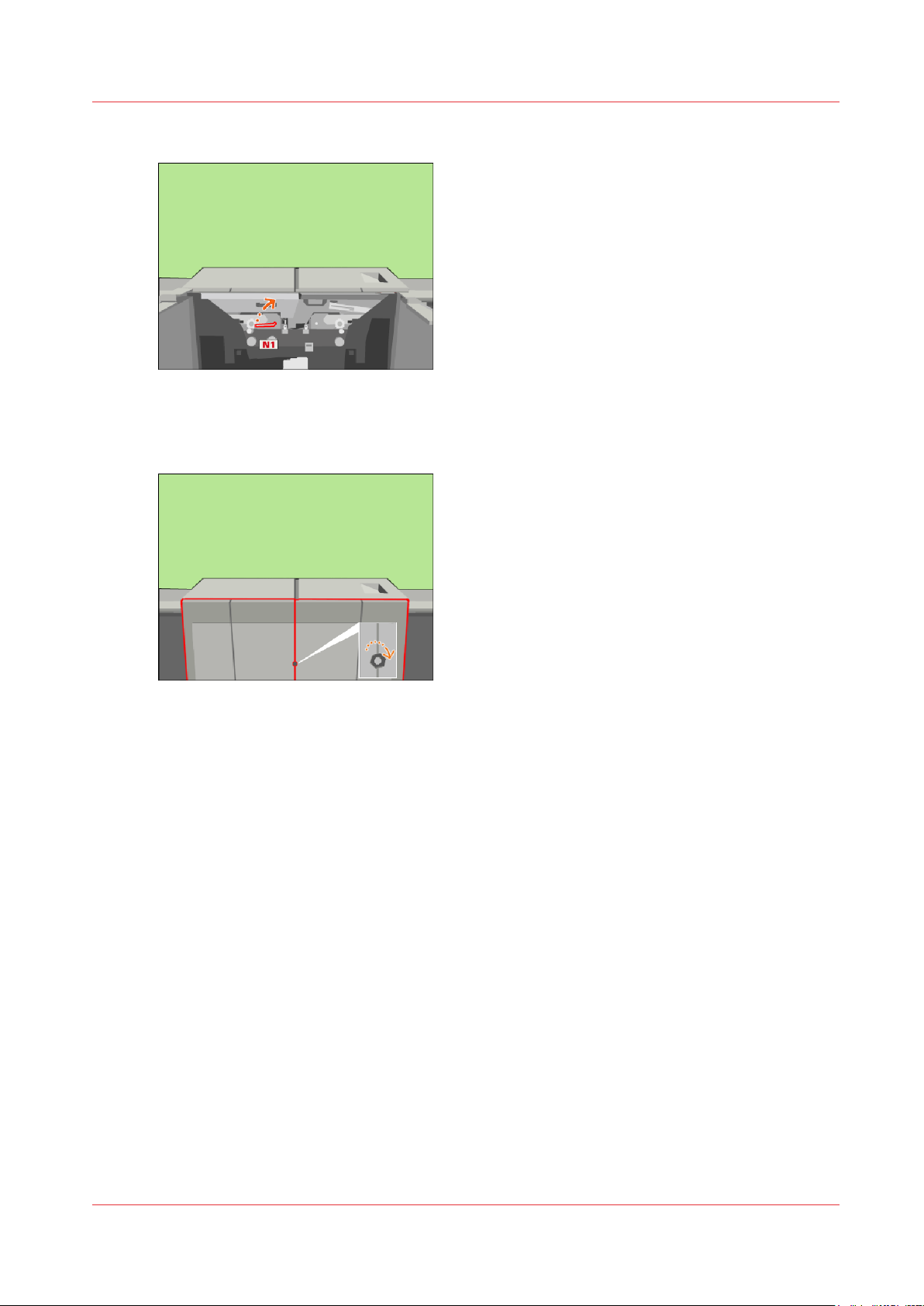
Use the service key to turn N1 clockwise.
4.
[33] Lock the clean unit
Close the front doors.
5.
Use socket wrench 10 to tighten the bolt of the front doors.
6.
Lock the clean unit (left)
[34] Close the front doors
On the operator panel, confirm that you successfully locked the clean unit.
7.
Press [Stop] to close the maintenance screen. The machine is turned on.
8.
Océ VarioPrint 6000 line
Chapter 2 - Maintenance tasks - Level 1
35
Page 36
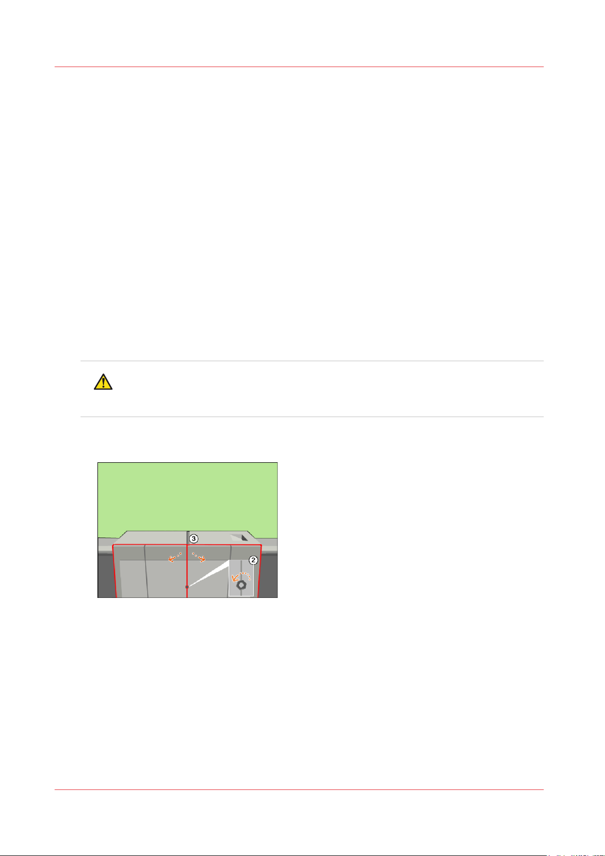
Lock the clean unit (right)
Lock the clean unit (right)
Introduction
This procedure is only intended for key operators who received the special maintenance training.
When to do
After you replaced the cleaners
you accidentally forgot to lock a clean unit after you replaced the cleaners, the machine will
detect this during the initialization. Then the operator panel will display this maintenance task.
Required tools
Service key (supplied with the machine)
Socket wrench 10 (supplied with the machine)
Procedure
Press [Start] to start the maintenance wizard.
1.
At the start of the procedure, the machine is turned off.
Use socket wrench 10 to loosen the bolt of the front doors (2).
2.
Open the front doors (3).
3.
Replace the cleaners
on page 14, you must restart the machine. If
CAUTION
Wait until the machine is turned off. Opening the doors too soon can possibly cause
injury.
[35] Open the front doors
Chapter 2 - Maintenance tasks - Level 1
36
Océ VarioPrint 6000 line
Page 37
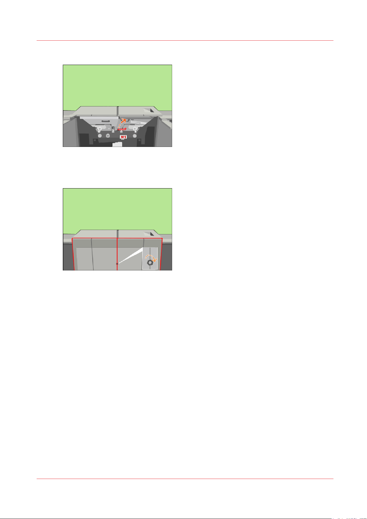
Use the service key to turn M1 clockwise.
4.
[36] Lock the clean unit
Close the front doors.
5.
Use socket wrench 10 to tighten the bolt of the front doors.
6.
Lock the clean unit (right)
[37] Close the front doors
On the operator panel, confirm that you successfully locked the clean unit.
7.
Press [Stop] to close the maintenance screen. The machine is turned on.
8.
Océ VarioPrint 6000 line
Chapter 2 - Maintenance tasks - Level 1
37
Page 38

Lock the clean unit (right)
Chapter 2 - Maintenance tasks - Level 1
38
Océ VarioPrint 6000 line
Page 39

Chapter 3
Maintenance tasks - Level 2
Page 40
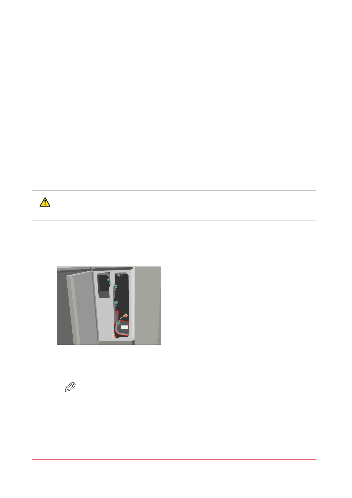
B4
Remove sheets from the process modules
Remove sheets from the process modules
Remove sheets from the interface module
Introduction
During the printing process, sheets can get stuck in one or more process modules. Sometimes,
you can only remove these sheets when the machine is off, for example when a sheet is stuck in
the preheat unit. Then, only trained operators are allowed to remove these sheets. This section
describes the procedure to check all the modules and remove the sheets.
Required tools
Service key (supplied with the machine)
Socket wrench 10 (supplied with the machine)
Heat-resistant gloves (supplied with the machine)
CAUTION
Certain parts of the machine may be hot. Therefore, always use the special heat- and oilresistant fuser gloves.
Procedure
Open the front door of the interface module.
1.
Remove the sheets at B4.
2.
[38] Remove the sheets at B4
Close B4. Also push the rear side of B4 to close B4 completely.
3.
Close the front door of the interface module.
4.
NOTE
After you checked the interface module for sheets, you must press [Next] on the
operator panel to continue.
Chapter 3 - Maintenance tasks - Level 2
40
Océ VarioPrint 6000 line
Page 41
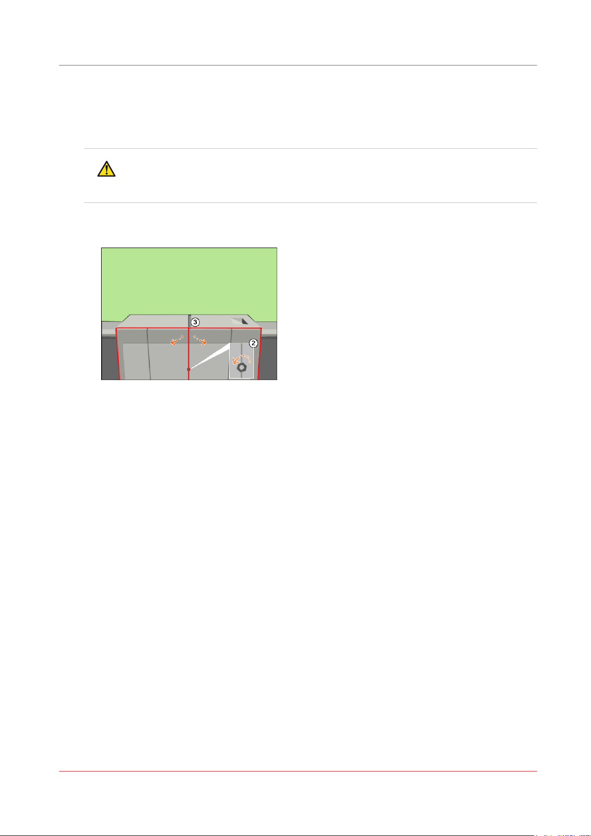
Open the doors
Procedure
At the start of the procedure, the machine is turned off.
1.
CAUTION
Wait until the machine is turned off. Opening the doors too soon can possibly cause
injury.
Use socket wrench 10 to loosen the bolt of the front doors (2).
2.
Open the front doors (3).
3.
Open the doors
[39] Open the front doors
Océ VarioPrint 6000 line
Chapter 3 - Maintenance tasks - Level 2
41
Page 42
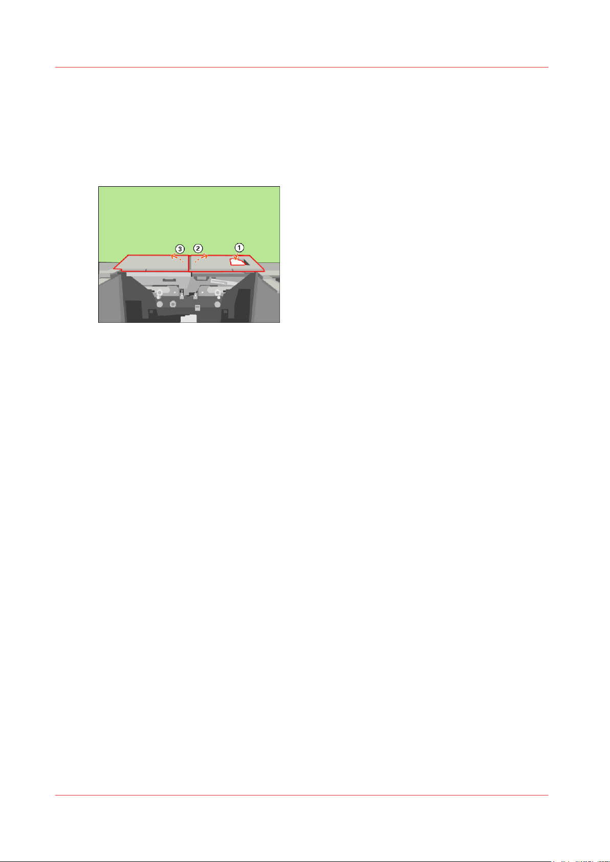
Remove sheets at the top cover
Remove sheets at the top cover
Procedure
Remove the sheets at the top cover (1).
1.
Lift the right-hand top cover to the upper position (2).
2.
Lift the left-hand top cover to the upper position (3).
3.
[40] Remove the sheets at the top cover
Chapter 3 - Maintenance tasks - Level 2
42
Océ VarioPrint 6000 line
Page 43
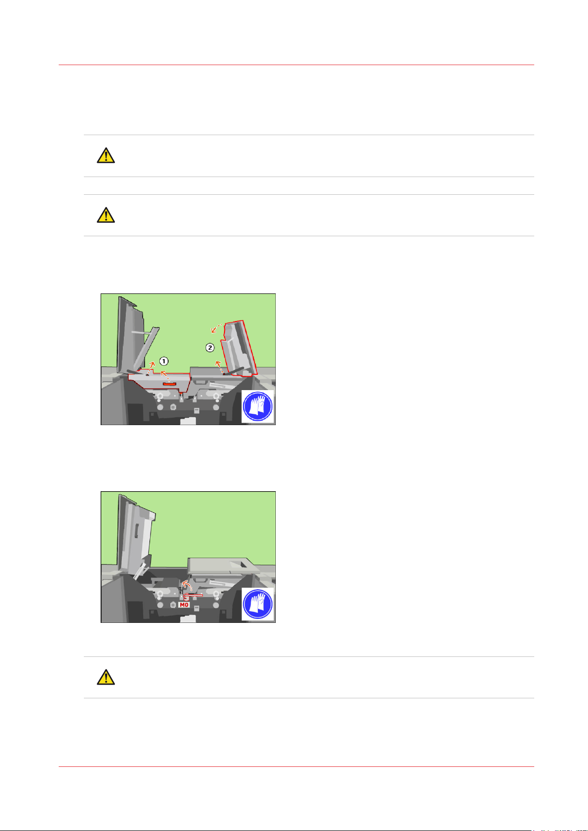
Remove sheets at the inner covers
Procedure
CAUTION
Hot area. Use heat-resistant gloves.
CAUTION
Make sure that the left-hand inner cover is locked in the upper position.
Remove the sheets at the inner covers.
1.
Unlock the left-hand inner cover and lift the left-hand inner cover to the upper position (1).
2.
Unlock and lower the right-hand top cover (2).
3.
Remove sheets at the inner covers
[41] Open the inner covers (1 of 2)
Only when the M0 lock is present, turn the M0 lock with the service key counter-clockwise to
4.
unlock the inner right-hand cover.
[42] When the M0 lock is present, unlock the inner right-hand cover
CAUTION
Make sure that the right-hand inner cover is locked in the upper position.
Océ VarioPrint 6000 line
Chapter 3 - Maintenance tasks - Level 2
43
Page 44
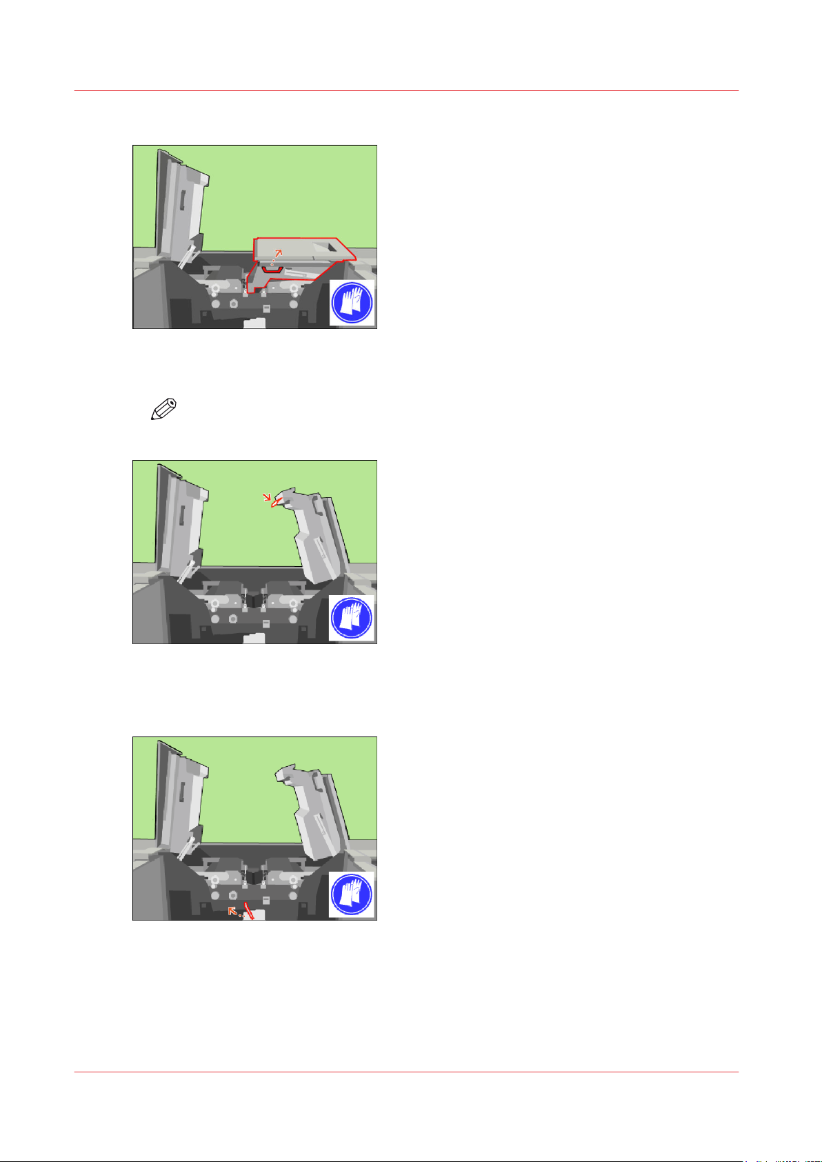
Remove sheets at the inner covers
Lift the right-hand inner cover to the upper position.
5.
[43] Open the inner covers (2 of 2)
Remove the sheets from the receiving unit.
6.
NOTE
Always pull out the sheet straight and in horizontal direction.
[44] Remove the sheets from the receiving unit
Use the service key to turn the axle of the transfuse pinch clockwise. The transfuse pinch gets
7.
unlocked.
[45] Unlock the transfuse pinch
Chapter 3 - Maintenance tasks - Level 2
44
Océ VarioPrint 6000 line
Page 45
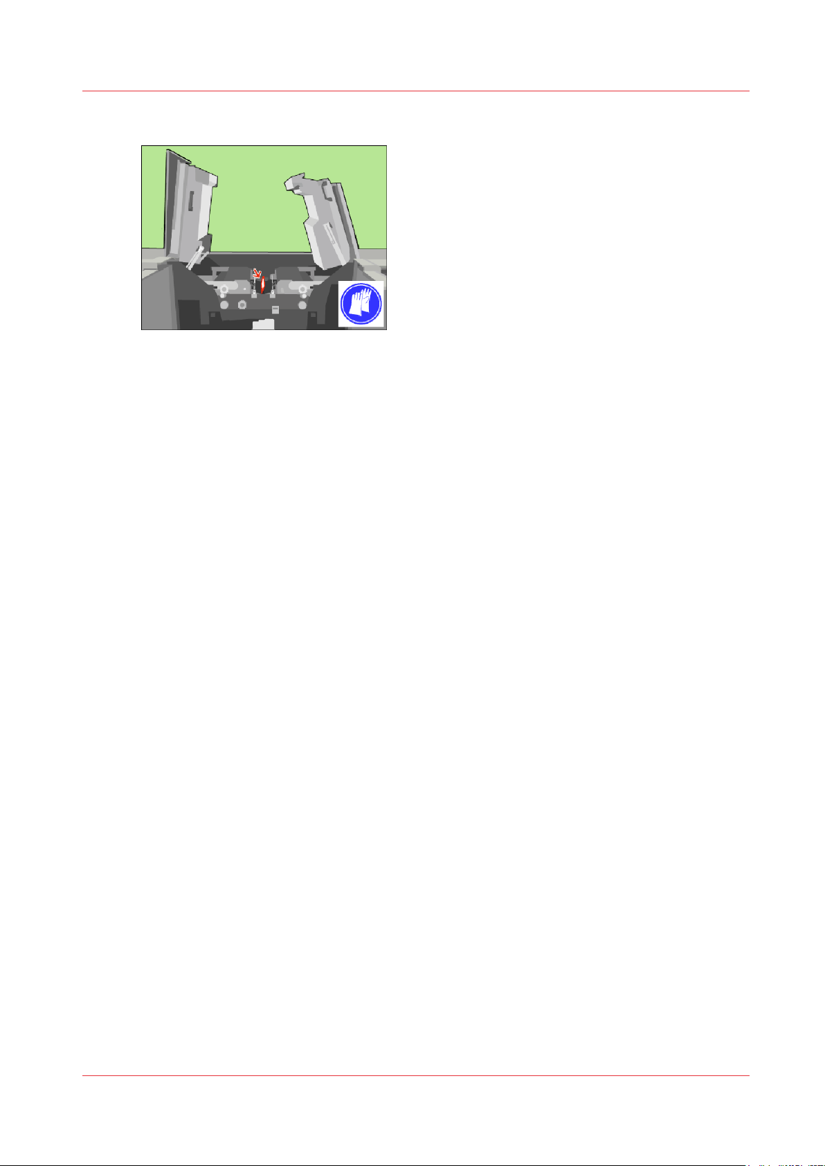
Remove sheets at the inner covers
Remove the sheets from the transfuse pinch.
8.
[46] Remove the sheets from the transfuse pinch
When the optional light-weight media module is installed, you might have to remove the air
9.
guidance unit to remove the sheets.
Remove the air guidance unit
on page 95.
Remove the sheets.
Install the air guidance unit
on page 97.
Océ VarioPrint 6000 line
Chapter 3 - Maintenance tasks - Level 2
45
Page 46
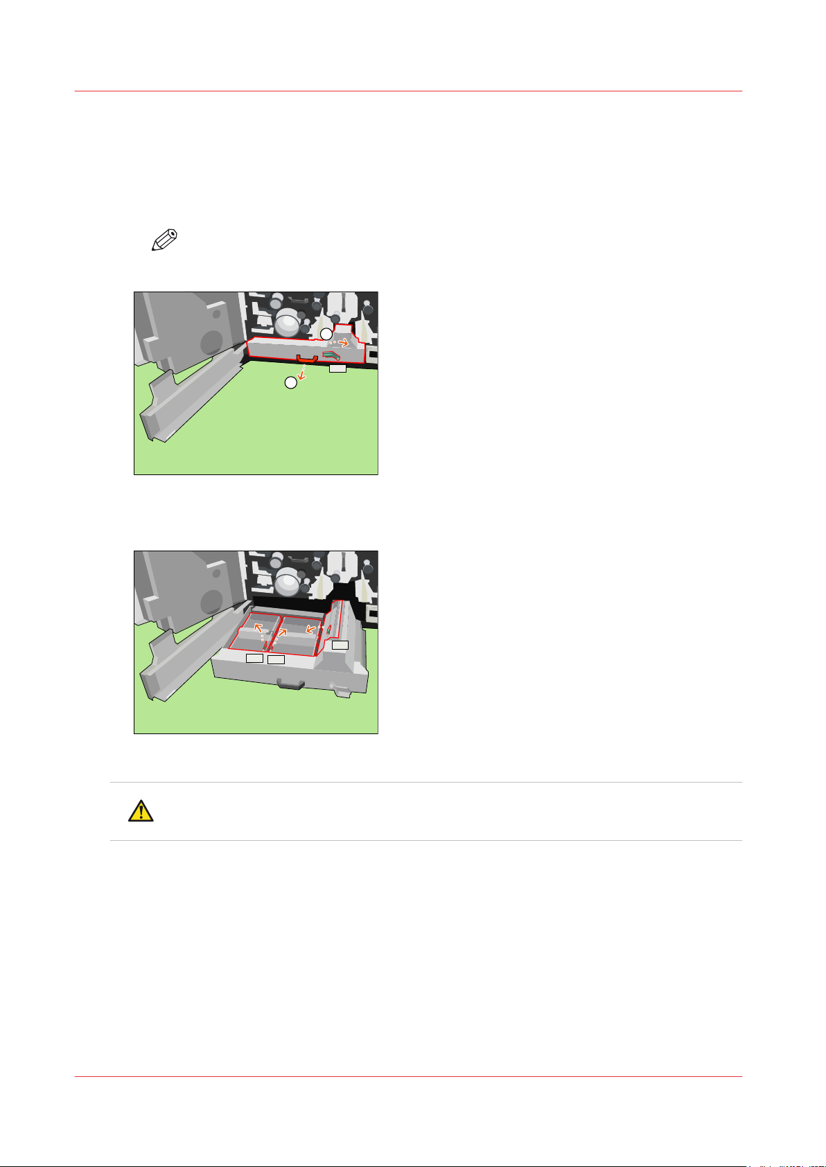
2
1
C1
C2
C3
C4
Remove sheets from the registration unit
Remove sheets from the registration unit
Procedure
Turn handle C1 clockwise (1).
1.
Open drawer C1 (2).
2.
NOTE
Opening the drawer can be difficult due to jammed media.
[47] Open the registration unit
Remove the sheets at C2, C3 and C4.
3.
[48] Remove the sheets from the registration unit
CAUTION
Hot area.
46
Chapter 3 - Maintenance tasks - Level 2
Océ VarioPrint 6000 line
Page 47
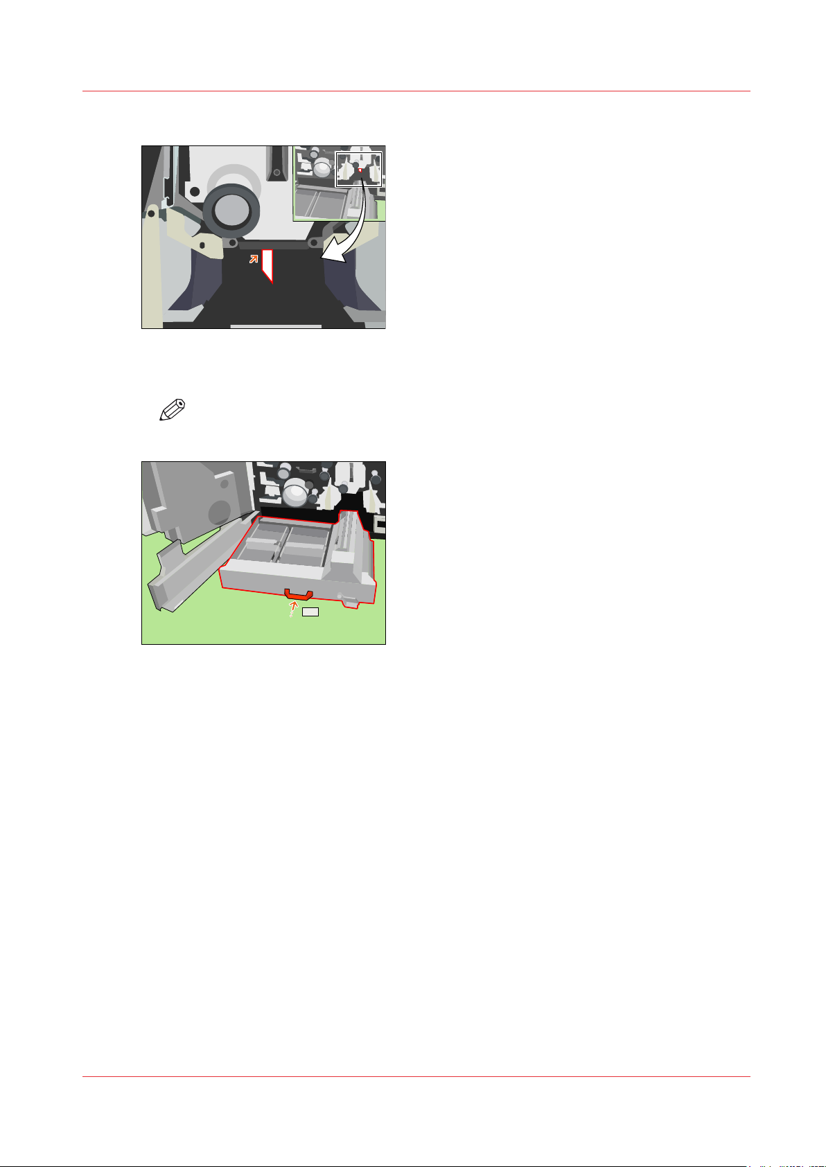
Remove the sheets below the preheat unit.
C1
4.
[49] Remove the sheets below the preheat unit
Close drawer C1.
5.
NOTE
Do not turn handle C1.
Remove sheets from the registration unit
[50] Close drawer C1
Océ VarioPrint 6000 line
Chapter 3 - Maintenance tasks - Level 2
47
Page 48
1
2
2
Remove the preheat unit
Remove the preheat unit
Procedure
CAUTION
Hot area. Use heat-resistant gloves.
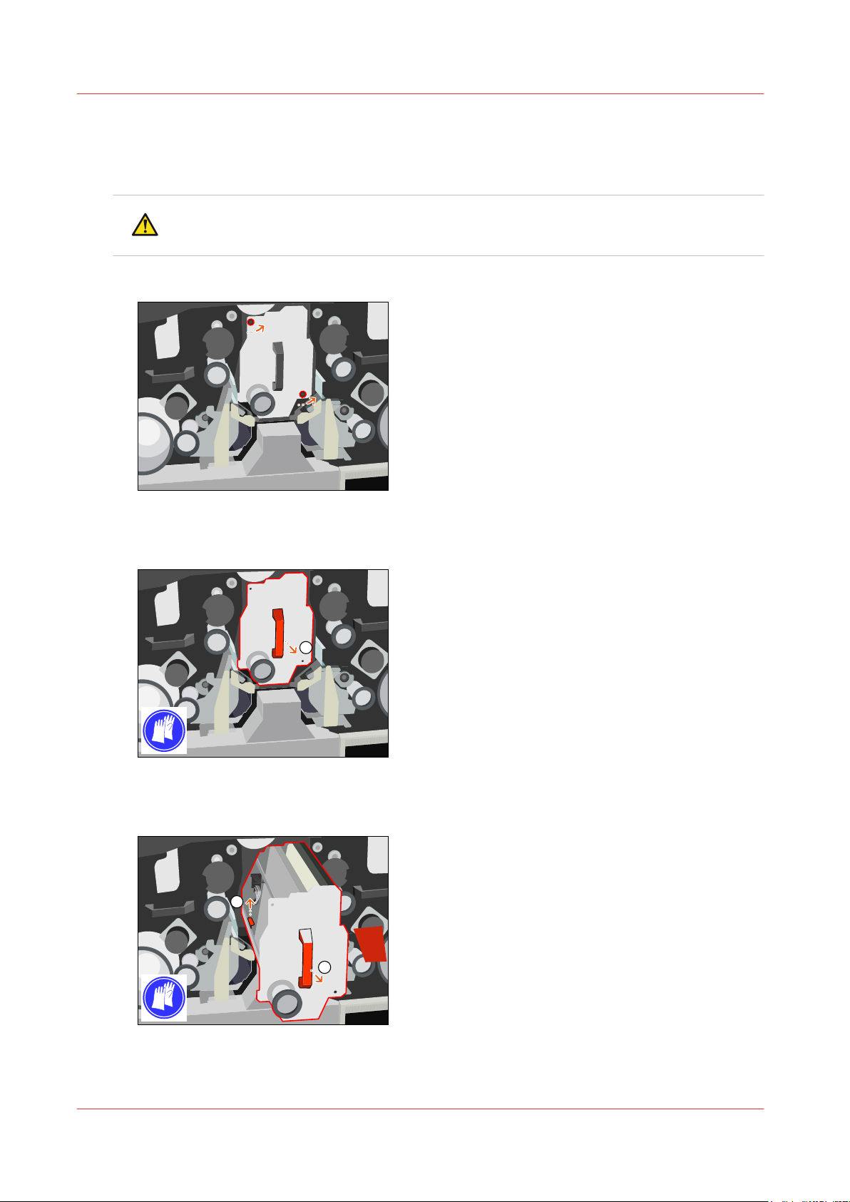
Remove the bolts of the preheat unit to unlock the preheat unit.
1.
[51] Unlock the preheat unit
Pull out the unit as far as possible.
2.
[52] Pull the unit out
Lift the red handle and pull the unit further outwards.
3.
[53] Pull the unit out further
Lower the front of the unit and remove the unit.
4.
Chapter 3 - Maintenance tasks - Level 2
48
Océ VarioPrint 6000 line
Page 49

Put the unit on a heat-resistant base. Make sure that the left-hand side is on top.
5.
Remove the preheat unit
Océ VarioPrint 6000 line
Chapter 3 - Maintenance tasks - Level 2
49
Page 50
Disassemble and assemble the preheat unit
Disassemble and assemble the preheat unit
Procedure
CAUTION
Hot area. Use heat-resistant gloves.
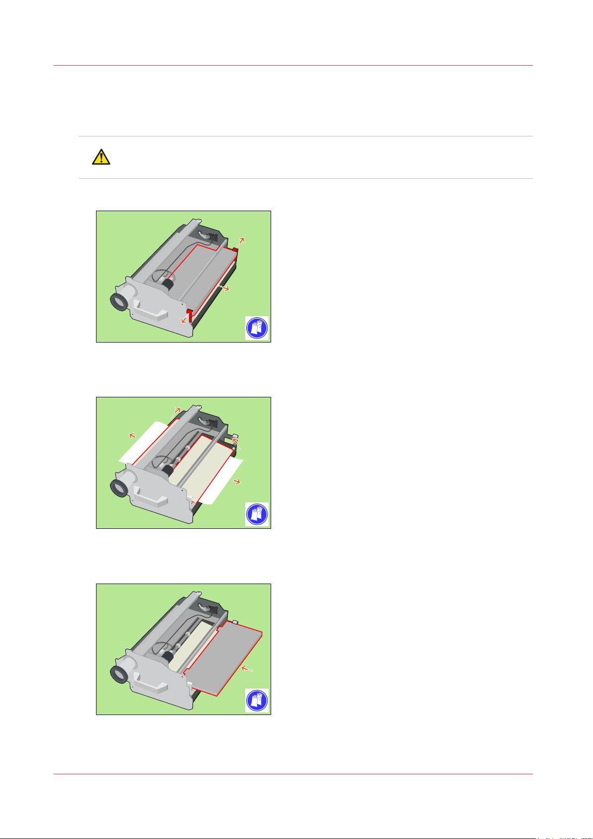
Press both red leaf springs at the preheat unit plate outwards and pull out the plate.
1.
[54] Disassemble the preheat unit
Turn both belts to remove the sheets inside the preheat unit.
2.
[55] Turn the belts
Put the preheat unit plate back.
3.
[56] Assemble the preheat unit
Chapter 3 - Maintenance tasks - Level 2
50
Océ VarioPrint 6000 line
Page 51

Remove the sheets below the transfer unit.
4.
[57] Remove the sheets below the transfer unit
Disassemble and assemble the preheat unit
Océ VarioPrint 6000 line
Chapter 3 - Maintenance tasks - Level 2
51
Page 52
1
2
3
3
Install the preheat unit
Install the preheat unit
Procedure
CAUTION
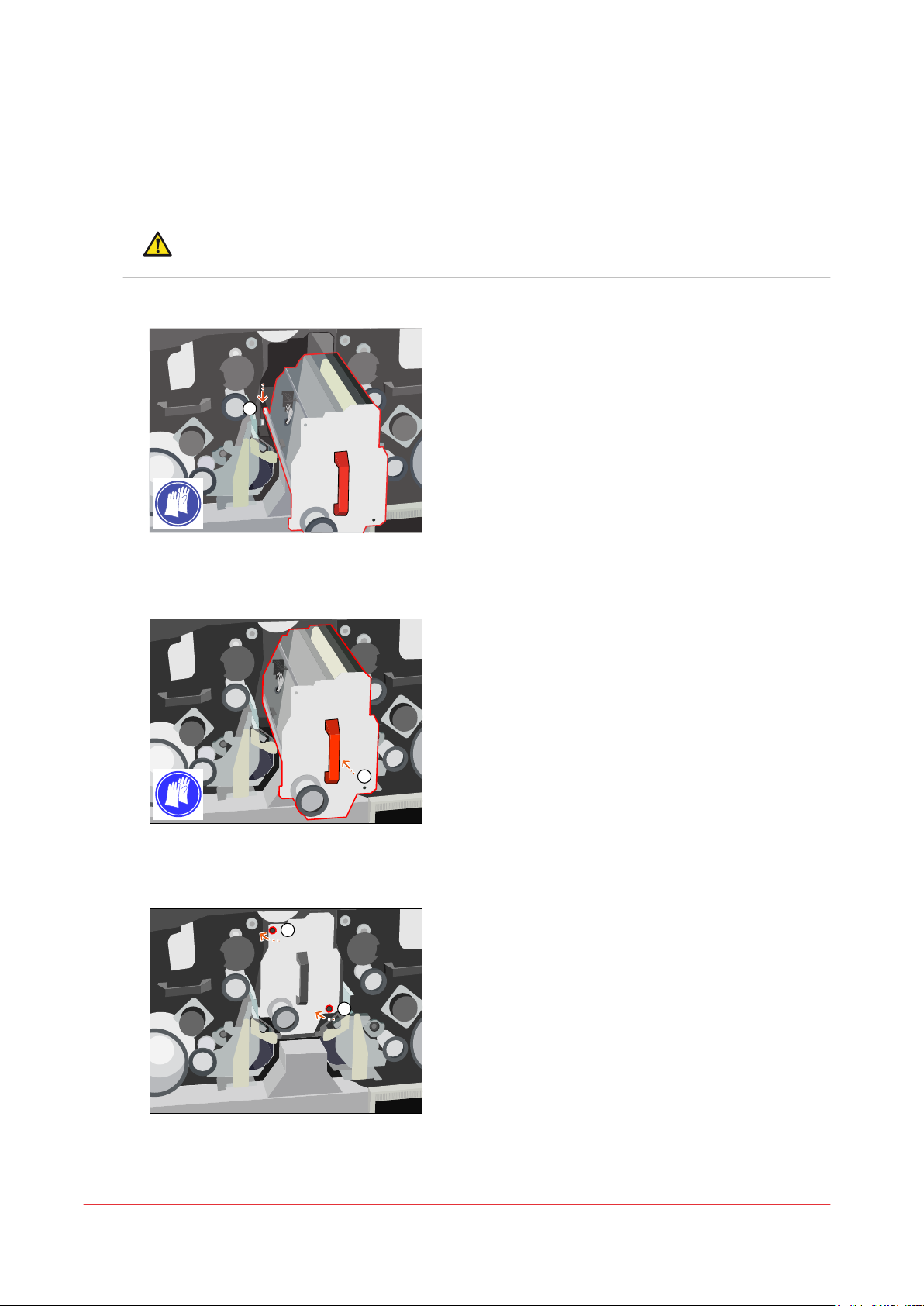
Hot area. Use heat-resistant gloves.
Put the slider wheels of the preheat unit behind the slider wheels of the machine.
1.
[58] Install the preheat unit
Put the preheat unit in horizontal position and push the unit into the machine.
2.
[59] Push the preheat unit into the machine
Replace and tighten the bolts of the preheat unit.
3.
[60] Tighten the bolts
Chapter 3 - Maintenance tasks - Level 2
52
Océ VarioPrint 6000 line
Page 53

Turn handle C1 anticlockwise to lock the registration unit.
C1
4.
[61] Lock the registration unit
Install the preheat unit
Océ VarioPrint 6000 line
Chapter 3 - Maintenance tasks - Level 2
53
Page 54
Unlock the clean units
Unlock the clean units
Procedure
CAUTION
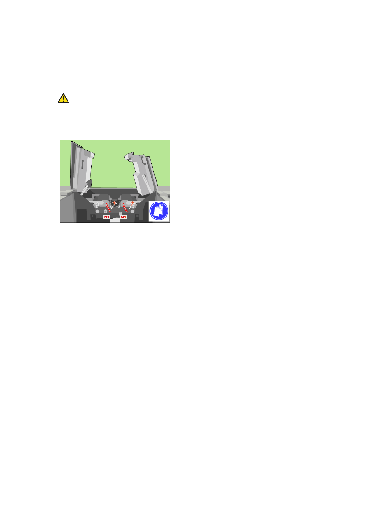
Hot area. Use heat-resistant gloves.
Use the service key to turn N1 counter-clockwise.
1.
Use the service key to turn M1 counter-clockwise.
2.
[62] Unlock the clean units
Chapter 3 - Maintenance tasks - Level 2
54
Océ VarioPrint 6000 line
Page 55
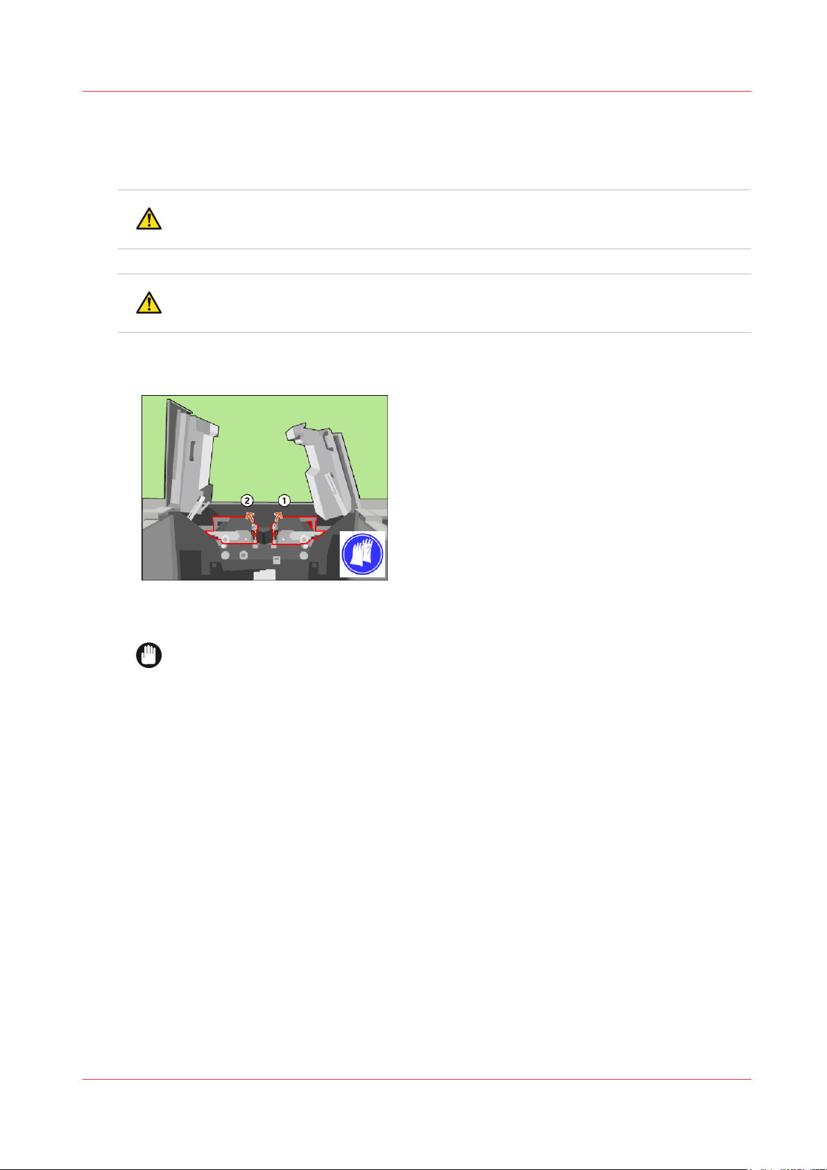
Lift the clean units
Procedure
CAUTION
Hot area. Use heat-resistant gloves.
CAUTION
Make sure that both clean units are locked in the upper position.
Use the red handle to lift the right-hand clean unit to the upper position (1).
1.
Use the red handle to lift the left-hand clean unit to the upper position (2).
2.
Lift the clean units
[63] Lift the clean units
When you press [Next] on the operator panel, a dialog box appears.
IMPORTANT
A sheet on one of the spiral cleaners or on both spiral cleaners will seriously damage the
machine.
Check whether there is a sheet on one of the spiral cleaners.
3.
If not, go to step 4. If there is, go to step 5.
Press [No] if the spiral cleaners do not have sheets on them.
4.
Press [Yes] if there is a sheet on one of the spiral cleaners. Now you must follow the procedures
5.
for removing, reconditioning and installating of the sheet cleaners and spiral cleaners
cleaners
on page 14.
Replace the
Océ VarioPrint 6000 line
Chapter 3 - Maintenance tasks - Level 2
55
Page 56
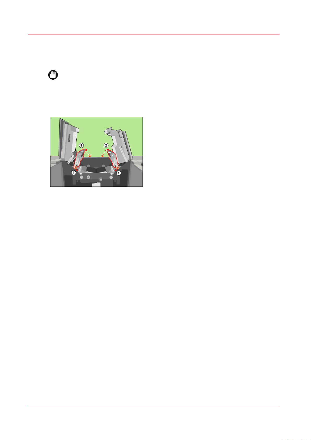
Lower the clean units
Lower the clean units
Procedure
IMPORTANT
Make sure that the clean units are in the lowest position.
Lift the right-hand clean unit and push the red handle to unlock the locking mechanism (1).
1.
Lower the right-hand clean unit into the locked position (2).
2.
Lift the left-hand clean unit and push the red handle to unlock the locking mechanism (3).
3.
Lower the left-hand clean unit into the locked position (4).
4.
[64] Lower the clean units
Chapter 3 - Maintenance tasks - Level 2
56
Océ VarioPrint 6000 line
Page 57
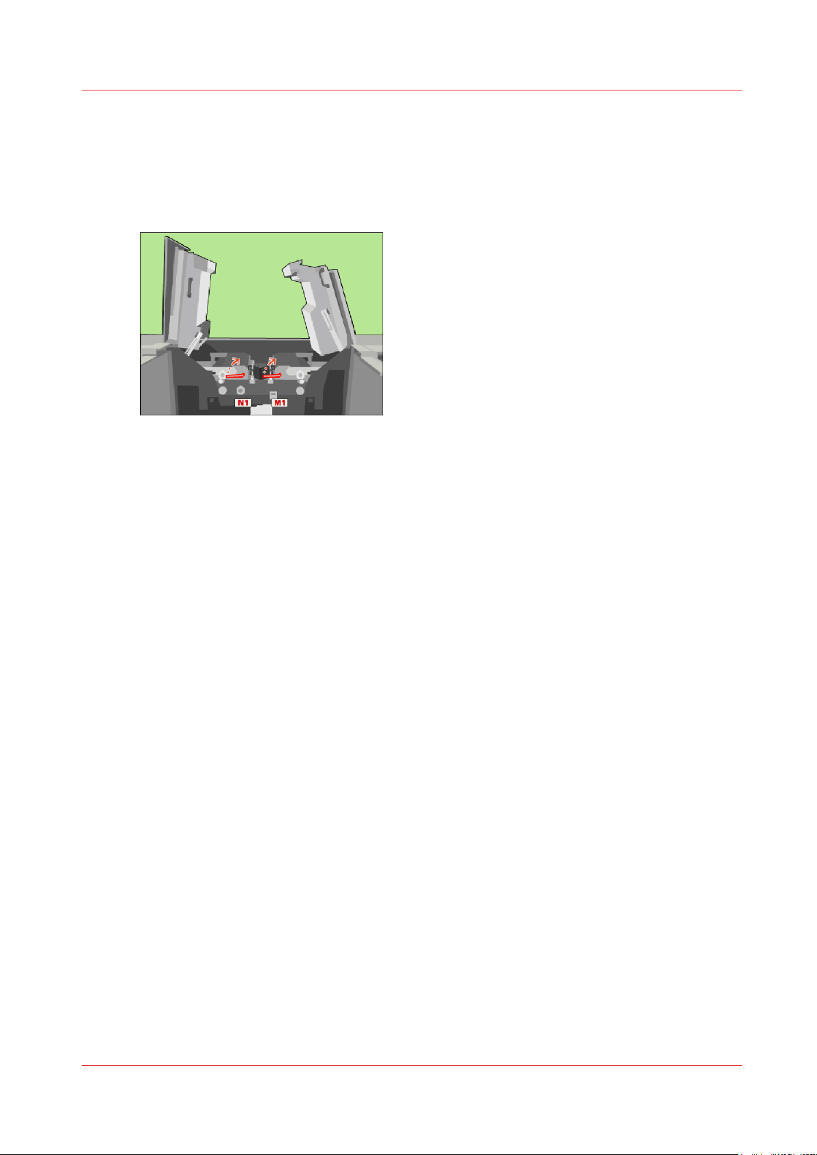
Lock the clean units
Procedure
Use the service key to turn N1 clockwise.
1.
Use the service key to turn M1 clockwise.
2.
[65] Lock the clean units
Lock the clean units
Océ VarioPrint 6000 line
Chapter 3 - Maintenance tasks - Level 2
57
Page 58
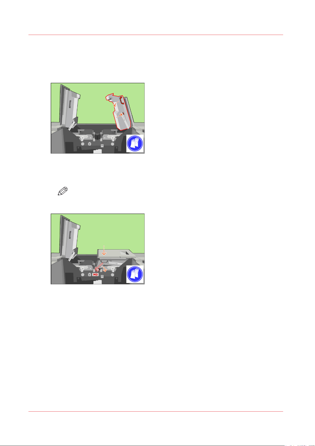
Close the covers
Close the covers
Procedure
Unlock and lower the right-hand inner cover.
1.
[66] Close the right-hand inner cover
Only when the M0 lock is present, push down the inner right-hand cover. Turn the M0 lock with
2.
the service key clockwise to lock the inner right-hand cover.
NOTE
Remove the service key.
[67] When the M0 lock is present, lock the inner right-hand cover
Lift the right-hand top cover to the upper position (1).
3.
Chapter 3 - Maintenance tasks - Level 2
58
Océ VarioPrint 6000 line
Page 59
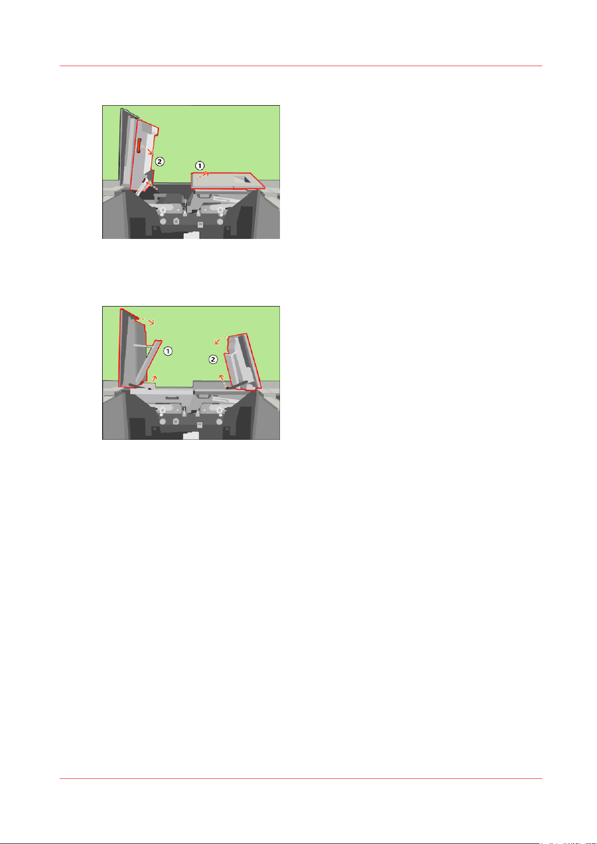
Unlock and lower the left-hand inner cover (2).
4.
[68] Close the left-hand inner cover
Close the left-hand top cover (1).
5.
Close the right-hand top cover (2).
6.
Close the covers
[69] Close the top covers
Océ VarioPrint 6000 line
Chapter 3 - Maintenance tasks - Level 2
59
Page 60

Finish the maintenance task
Finish the maintenance task
Procedure
Close the front doors.
1.
Use socket wrench 10 to tighten the bolt of the front doors.
2.
[70] Close the front doors
On the operator panel, confirm that you successfully removed the sheets.
3.
Press [Stop] to close the maintenance screen. The machine is turned on.
4.
Chapter 3 - Maintenance tasks - Level 2
60
Océ VarioPrint 6000 line
Page 61
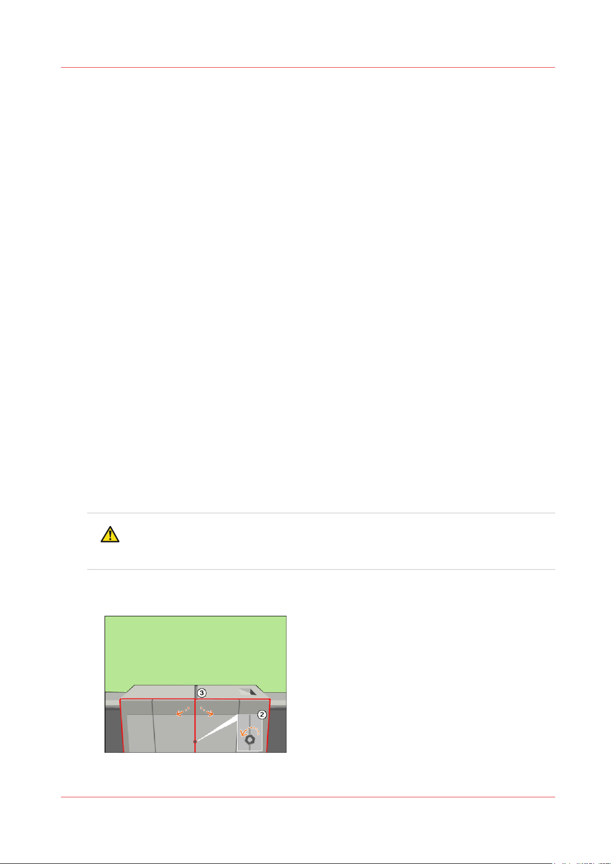
Clean the OPC belt (left)
Open the doors
Introduction
This procedure is only intended for key operators who received the special maintenance training.
When to do
When a pollution is visible at exact the same height on an A4 print or a letter print after each 6 to
8 prints.
Or when a pollution is visible on a print that is larger than the paper size of the bulk media used.
The pollution is visible on the operator side or the back side of a print (Z direction).
Before you begin
Make sure that you have the Cleaner J, the cleaning gloves and the offset pads at hand.
Required tools
Clean the OPC belt (left)
Service key (supplied with the machine)
Socket wrench 10 (supplied with the machine)
Cleaning gloves (supplied with the machine)
Procedure
Select the maintenance task from the list of the required and suggested maintenance tasks.
1.
[System] view -> maintenance section -> press the [Start maintenance] button.
Press [Start] to start the maintenance wizard.
2.
At the start of the procedure, the machine is turned off.
Use socket wrench 10 to loosen the bolt of the front doors (2).
3.
Open the lower door. Open the front doors (3).
4.
CAUTION
Wait until the machine is turned off. Opening the doors too soon can possibly cause
injury.
[71] Open the front doors
Océ VarioPrint 6000 line
Chapter 3 - Maintenance tasks - Level 2
61
Page 62
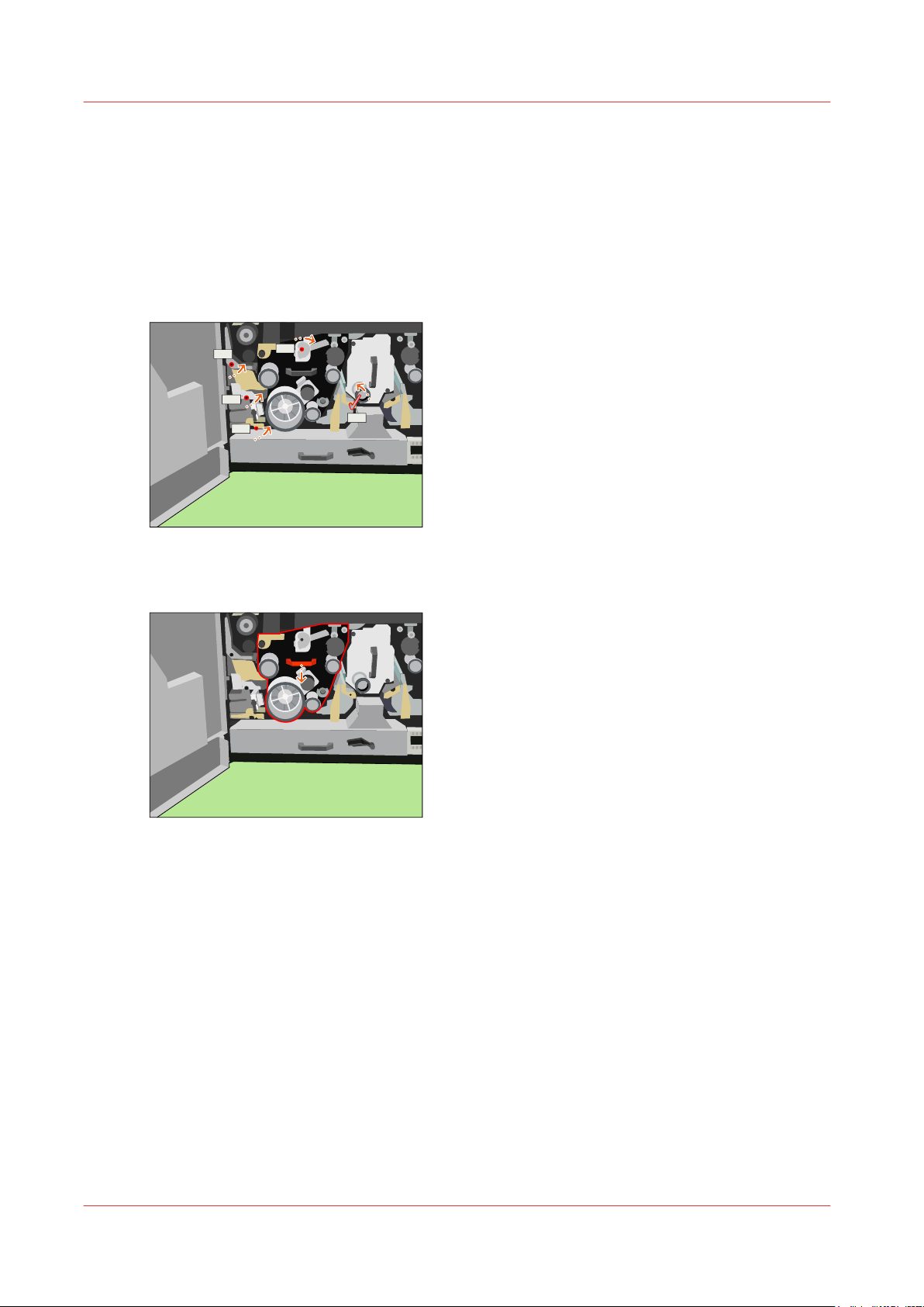
L1
L2
L3
L4
L5
Unlock the OPC unit (left)
Unlock the OPC unit (left)
Procedure
Use the service key to push and turn L1 counter-clockwise.
1.
Use the service key to turn L2 counter-clockwise.
2.
Use the service key to push and turn L3 counter-clockwise.
3.
Use the service key to push and turn L4 counter-clockwise.
4.
Use the service key to turn L5 clockwise.
5.
[72] Unlock the OPC unit
Use the red handle to move the OPC unit as far outward as possible.
6.
[73] Move the OPC unit out
62
Chapter 3 - Maintenance tasks - Level 2
Océ VarioPrint 6000 line
Page 63
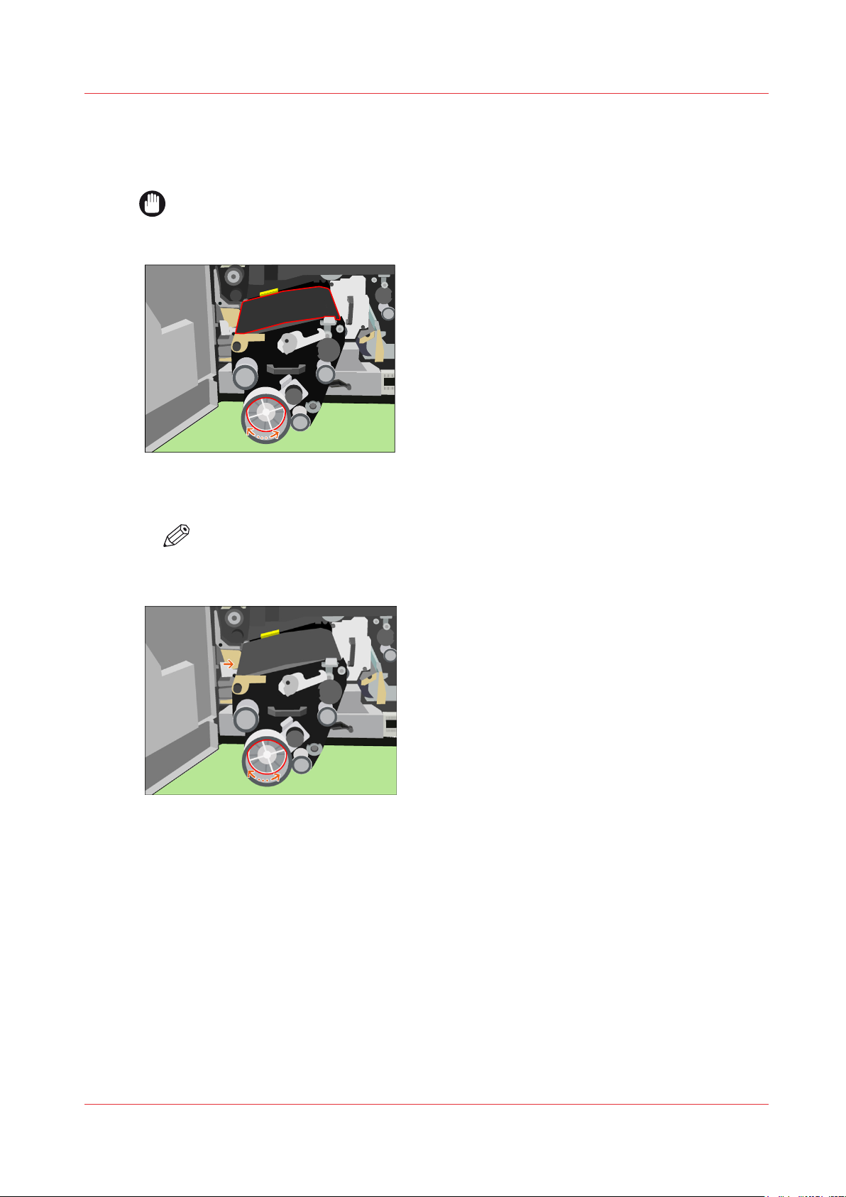
Clean the OPC belt (left)
Procedure
IMPORTANT
Do not touch the OPC belt with your fingers. Wear cleaning gloves.
Rotate the metal OPC pulley to locate the spot(s) on the OPC.
1.
[74] Rotate the OPC pulley to locate the spots
Clean the OPC belt (left)
Rotate the OPC pulley until the spot(s) are in the indicated area
2.
NOTE
In this area, the OPC has a hard bottom surface which is required to enable proper
cleaning without damaging the OPC belt.
[75] Position the spot(s) in the indicated area
Apply a small amount of Cleaner J on an offset pad.
3.
Clean the spot(s) with this offset pad.
4.
When you cannot clean the spots with Cleaner J, use Cleaner P.
Océ VarioPrint 6000 line
Chapter 3 - Maintenance tasks - Level 2
63
Page 64
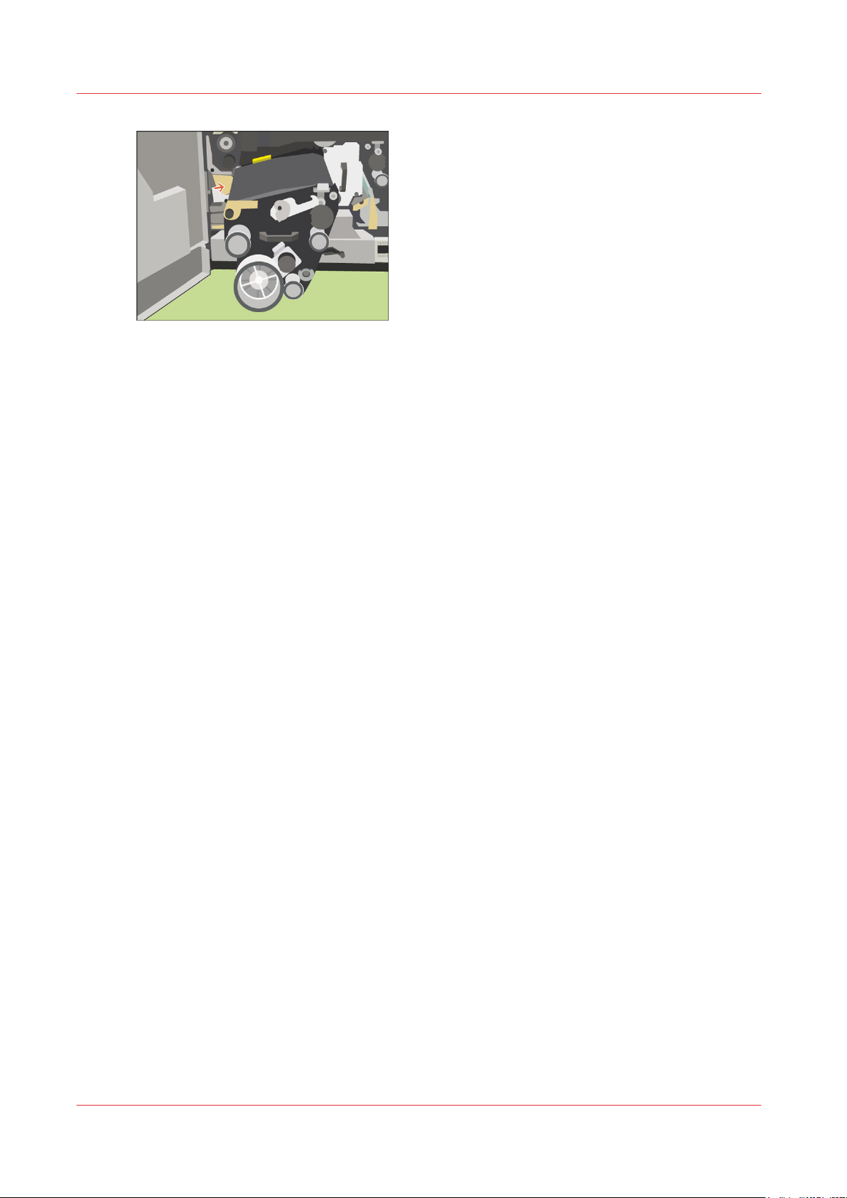
Clean the OPC belt (left)
[76] Clean the OPC
Carefully remove all Cleaner from the OPC belt. Use new offset pads for this.
5.
Chapter 3 - Maintenance tasks - Level 2
64
Océ VarioPrint 6000 line
Page 65
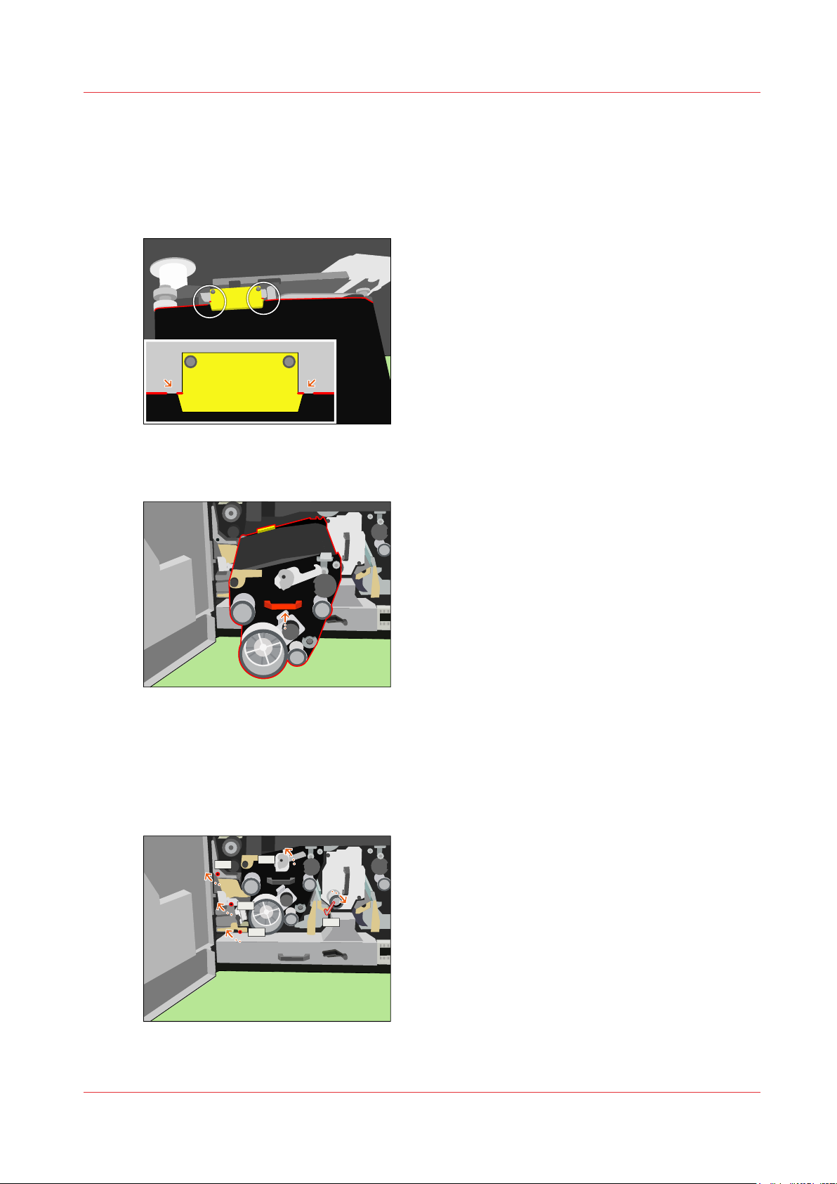
Lock the OPC unit (left)
L1
L2
L3
L4
L5
Procedure
Rotate the metal OPC pulley until the end of the back side of the OPC belt runs near (+/- 0.1 inch)
1.
the arrows of the yellow registration board.
[77] Reposition the OPC belt
Use the red handle to push the OPC unit inwards as far as possible.
2.
Lock the OPC unit (left)
[78] Move the OPC unit in
Use the service key to turn L5 counter-clockwise into the locked position.
3.
Use the service key to turn L4 clockwise into the locked position.
4.
Use the service key to turn L3 clockwise into the locked position.
5.
Use the service key to turn L2 clockwise into the locked position.
6.
Use the service key to turn L1 clockwise into the locked position.
7.
[79] Lock the OPC unit
Océ VarioPrint 6000 line
Chapter 3 - Maintenance tasks - Level 2
65
Page 66
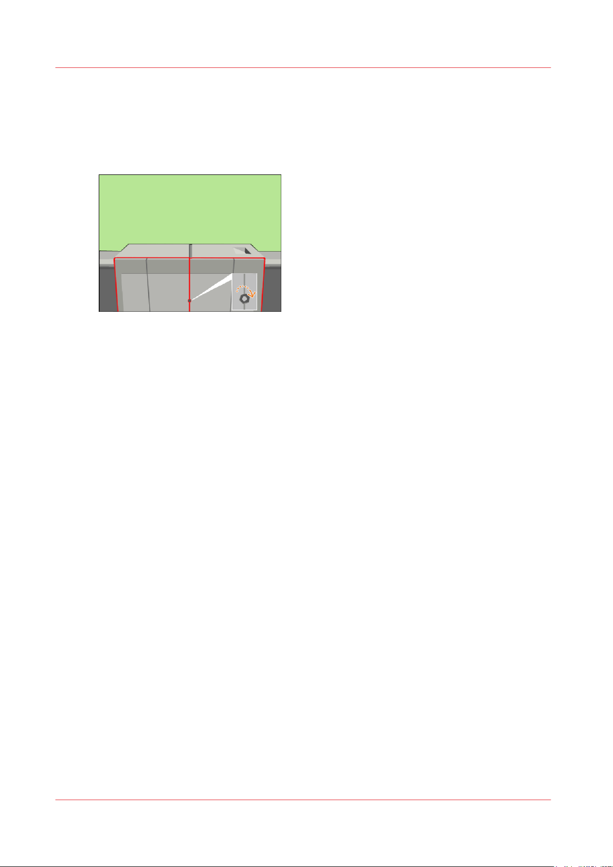
Finish the maintenance task
Finish the maintenance task
Procedure
Close the front doors.
1.
Use socket wrench 10 to tighten the bolt of the front doors.
2.
[80] Close the front doors
Close the lower door.
3.
On the operator panel, confirm that you successfully cleaned the OPC belt.
4.
Press [Stop] to close the maintenance screen. The machine is turned on.
5.
Chapter 3 - Maintenance tasks - Level 2
66
Océ VarioPrint 6000 line
Page 67
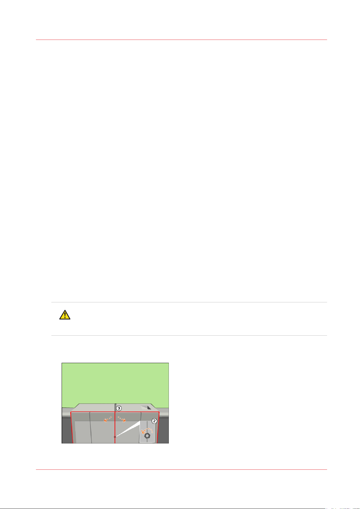
Clean the OPC belt (right)
Open the doors
Introduction
This procedure is only intended for key operators who received the special maintenance training.
When to do
When a pollution is visible at exact the same height on an A4 print or a letter print after each 6 to
8 prints.
Or when a pollution is visible on a print that is larger than the paper size of the bulk media used.
The pollution is visible on the operator side or the back side of a print (Z direction).
Before you begin
Make sure that you have the Cleaner J, the cleaning gloves and the offset pads at hand.
Required tools
Clean the OPC belt (right)
Service key (supplied with the machine)
Socket wrench 10 (supplied with the machine)
Cleaning gloves (supplied with the machine)
Procedure
Select the maintenance task from the list of the required and suggested maintenance tasks.
1.
[System] view -> maintenance section -> press the [Start maintenance] button.
Press [Start] to start the maintenance wizard.
2.
At the start of the procedure, the machine is turned off.
Use socket wrench 10 to loosen the bolt of the front doors (2).
3.
Open the lower door. Open the front doors (3).
4.
CAUTION
Wait until the machine is turned off. Opening the doors too soon can possibly cause
injury.
[81] Open the front doors
Océ VarioPrint 6000 line
Chapter 3 - Maintenance tasks - Level 2
67
Page 68
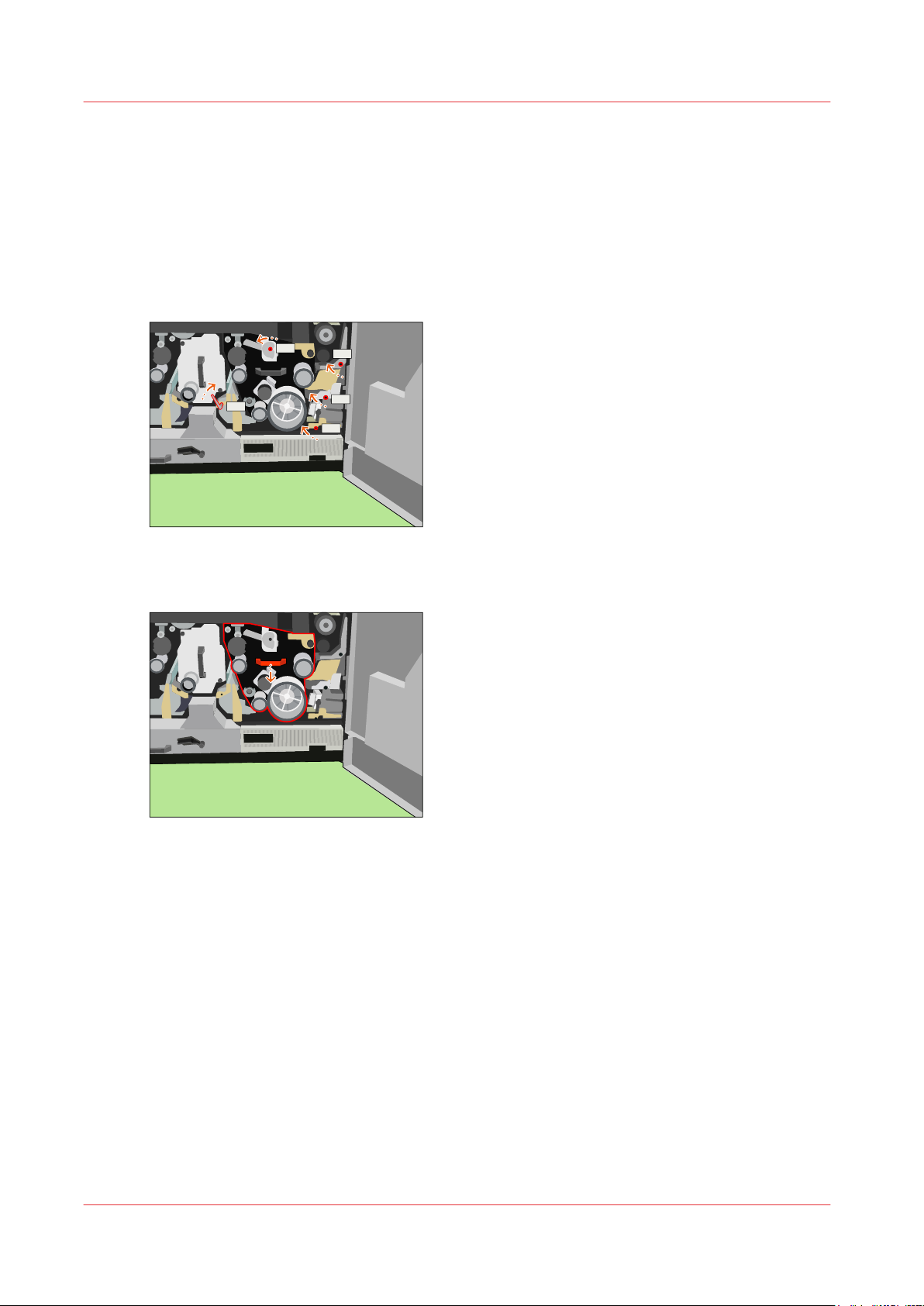
K1
K2
K3
K4
K5
Unlock the OPC unit (right)
Unlock the OPC unit (right)
Procedure
Use the service key to push and turn K1 clockwise.
1.
Use the service key to turn K2 clockwise.
2.
Use the service key to push and turn K3 clockwise.
3.
Use the service key to push and turn K4 clockwise.
4.
Use the service key to turn K5 counter-clockwise.
5.
[82] Unlock the OPC unit
Use the red handle to move the OPC unit as far outward as possible.
6.
[83] Move the OPC unit out
Chapter 3 - Maintenance tasks - Level 2
68
Océ VarioPrint 6000 line
Page 69
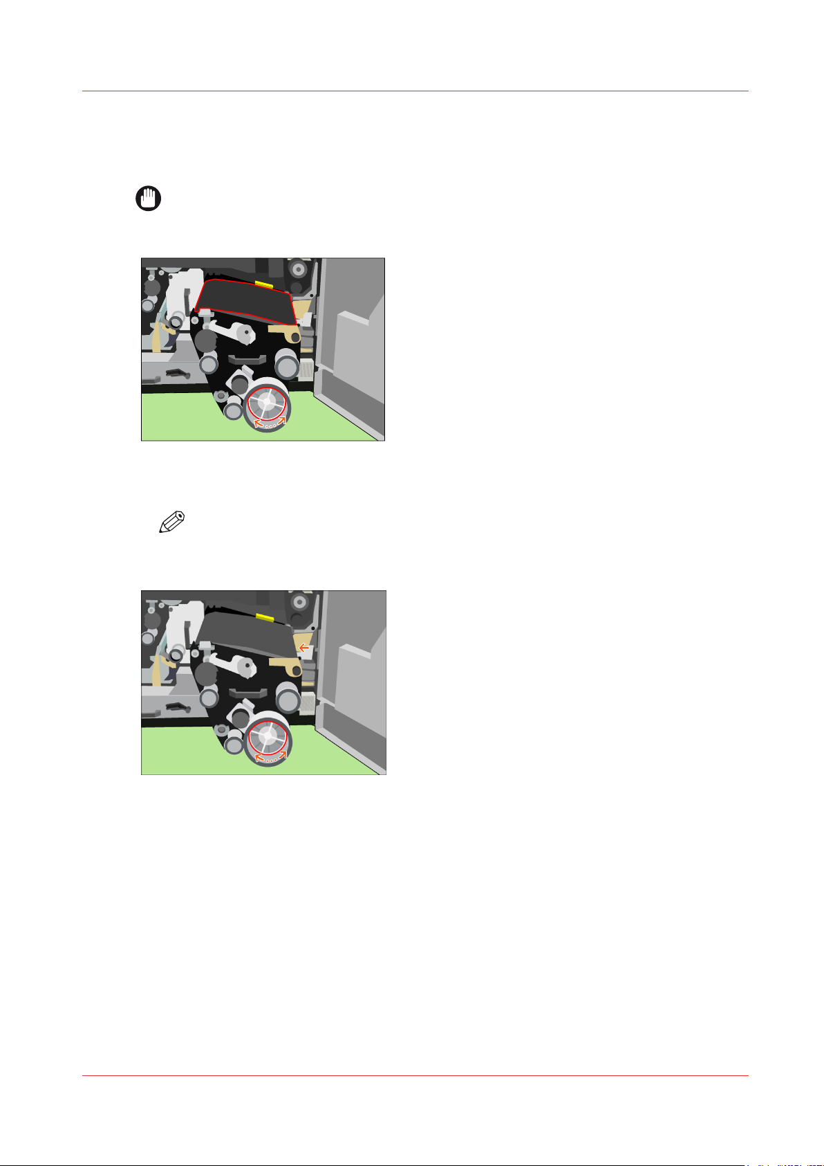
Clean the OPC belt (right)
Procedure
IMPORTANT
Do not touch the OPC belt with your fingers. Wear cleaning gloves.
Rotate the metal OPC pulley until the spots are visible.
1.
[84] Rotate the OPC pulley to locate the spots
Clean the OPC belt (right)
Rotate the OPC pulley until the spots are in the indicated area.
2.
NOTE
In this area, the OPC has a hard bottom surface which is required to enable proper
cleaning without damaging the OPC belt.
[85] Position the spots in the indicated area
Apply a small amount of Cleaner J on an offset pad.
3.
Clean any spots with this offset pad.
4.
When you cannot clean the spots with Cleaner J, use Cleaner P.
Océ VarioPrint 6000 line
Chapter 3 - Maintenance tasks - Level 2
69
Page 70
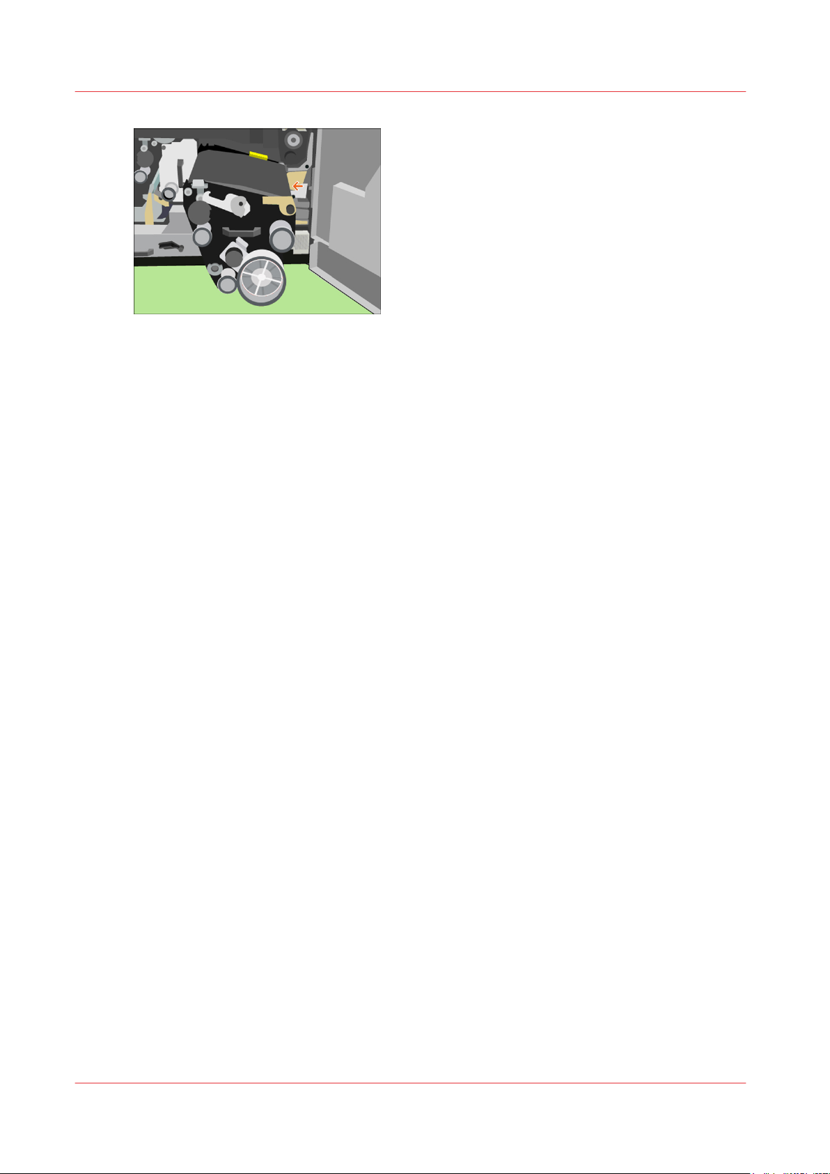
Clean the OPC belt (right)
[86] Clean the OPC
Carefully remove all Cleaner from the OPC belt. Use new offset pads for this.
5.
Chapter 3 - Maintenance tasks - Level 2
70
Océ VarioPrint 6000 line
Page 71
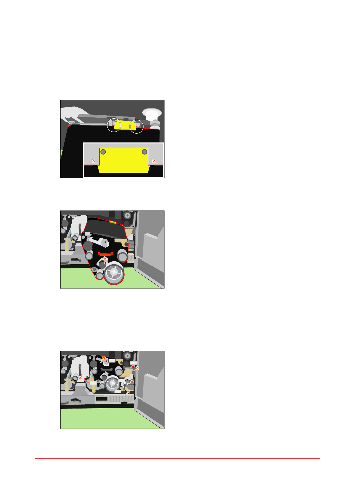
Lock the OPC unit (right)
K1
K2
K3
K4
K5
Procedure
Rotate the metal OPC pulley until the end of the back side of the OPC belt runs near (+/- 0.1 inch)
1.
the arrows of the yellow registration board.
[87] Reposition the OPC belt
Use the red handle to push the OPC unit inwards as far as possible.
2.
Lock the OPC unit (right)
[88] Move the OPC unit in
Use the service key to turn K5 clockwise into the locked position.
3.
Use the service key to turn K4 counter-clockwise into the locked position.
4.
Use the service key to turn K3 counter-clockwise into the locked position.
5.
Use the service key to turn K2 counter-clockwise into the locked position.
6.
Use the service key to turn K1 counter-clockwise into the locked position.
7.
[89] Lock the OPC unit
Océ VarioPrint 6000 line
Chapter 3 - Maintenance tasks - Level 2
71
Page 72
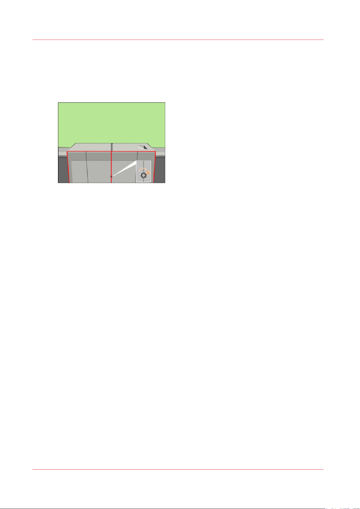
Finish the maintenance task
Finish the maintenance task
Procedure
Close the front doors.
1.
Use socket wrench 10 to tighten the bolt of the front doors.
2.
[90] Close the front doors
Close the lower door.
3.
On the operator panel, confirm that you successfully cleaned the OPC belt.
4.
Press [Stop] to close the maintenance screen. The machine is turned on.
5.
Chapter 3 - Maintenance tasks - Level 2
72
Océ VarioPrint 6000 line
Page 73

Clean the glue cleaning rollers
Open the doors and covers
Introduction
This procedure is only intended for key operators who received the special maintenance training.
When to do
Certain media may contain substances (for example ink or wax) that pollute the machine. This
pollution can lead to decreased image quality and/or machine damage. Depending on the amount
of substances, you must clean the glue cleaning rollers at a certain interval. Consult your service
technician if you need advise.
Before you begin
Make sure that the machine is switched off.
Required tools
Clean the glue cleaning rollers
Service key (supplied with the machine)
Socket wrench 10 (supplied with the machine)
Heat-resistant gloves (supplied with the machine)
Offset pads (supplied with the machine)
Large sheets of paper to protect the OPC
Océ Cleaner P (supplied with the machine)
Océ Cleaner K
Océ Cleaner T
CAUTION
Hot area. Use heat-resistant gloves.
Procedure
Select the maintenance task from the list of the required and suggested maintenance tasks.
1.
[System] view -> maintenance section -> press the [Start maintenance] button.
Press [Start] to start the maintenance wizard.
2.
CAUTION
Make sure that the machine is switched off. Opening the doors too soon can possibly
cause injury.
Use socket wrench 10 to loosen the bolt of the front doors (2).
3.
Océ VarioPrint 6000 line
Chapter 3 - Maintenance tasks - Level 2
73
Page 74
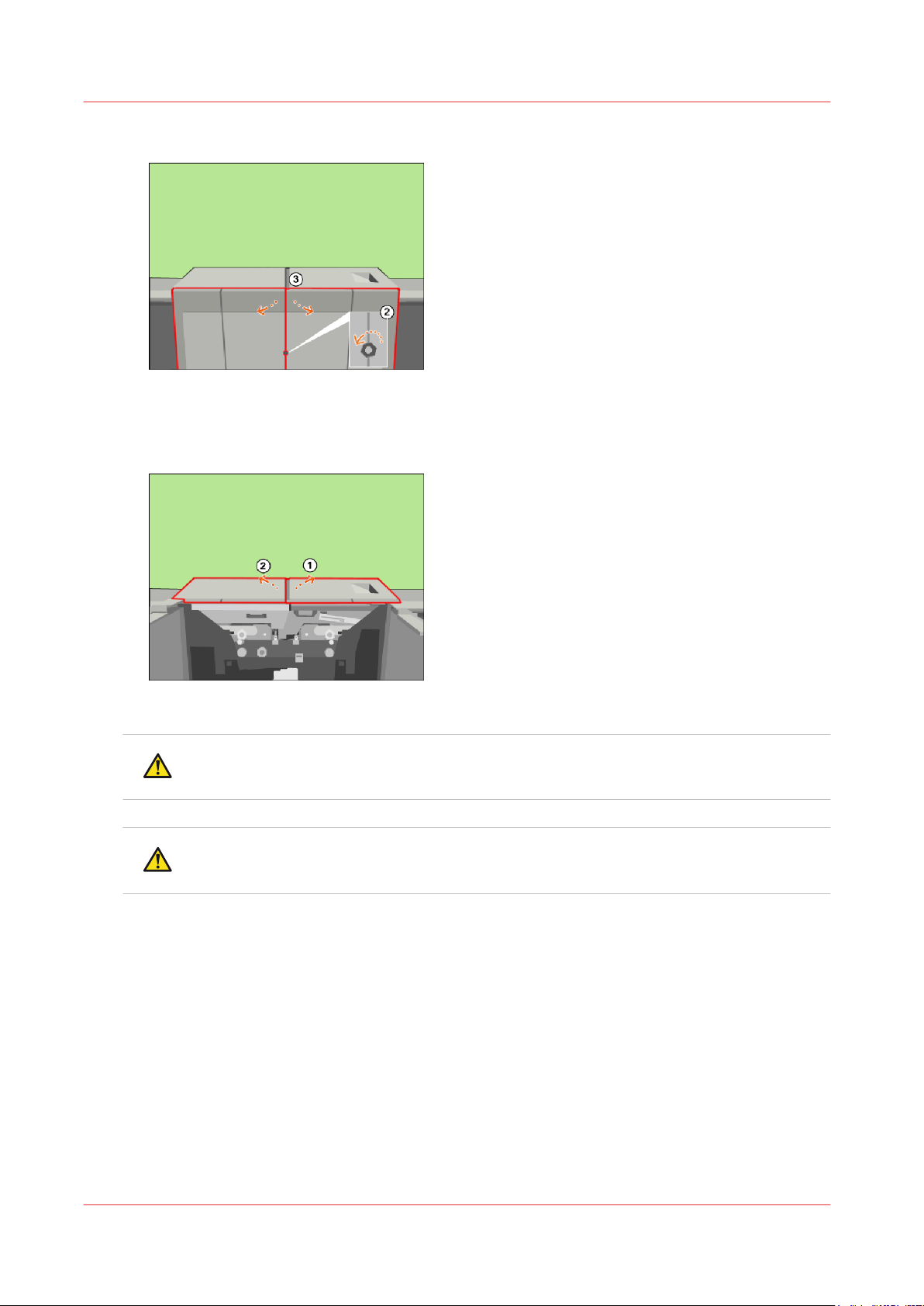
Open the doors and covers
Open the front doors (3).
4.
[91] Open the front doors
Lift the right-hand top cover to the upper position (1).
5.
Lift the left-hand top cover to the upper position (2).
6.
[92] Lift the top covers
CAUTION
Hot area. Use heat-resistant gloves.
CAUTION
Make sure that the left-hand inner cover is locked in the upper position.
Unlock the left-hand upper cover and lift the left-hand inner cover to the upper position (1).
7.
Chapter 3 - Maintenance tasks - Level 2
74
Océ VarioPrint 6000 line
Page 75
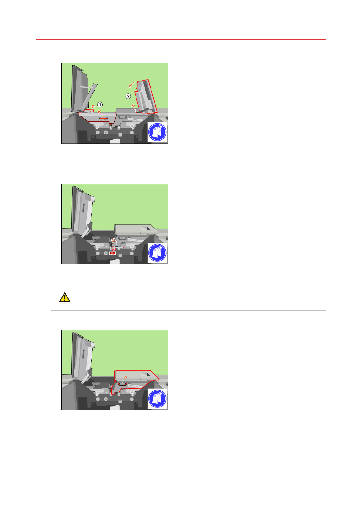
Open the doors and covers
Unlock and lower the right-hand top cover (2).
8.
[93] Lift the left-hand inner cover
Only when the M0 lock is present, turn the M0 lock with the service key counter-clockwise to
9.
unlock the inner right-hand cover.
[94] When the M0 lock is present, unlock the inner right-hand cover
CAUTION
Make sure that the right-hand inner cover is locked in the upper position.
Lift the right-hand inner cover to the upper position.
10.
[95] Lift the right-hand inner cover
Océ VarioPrint 6000 line
Chapter 3 - Maintenance tasks - Level 2
75
Page 76
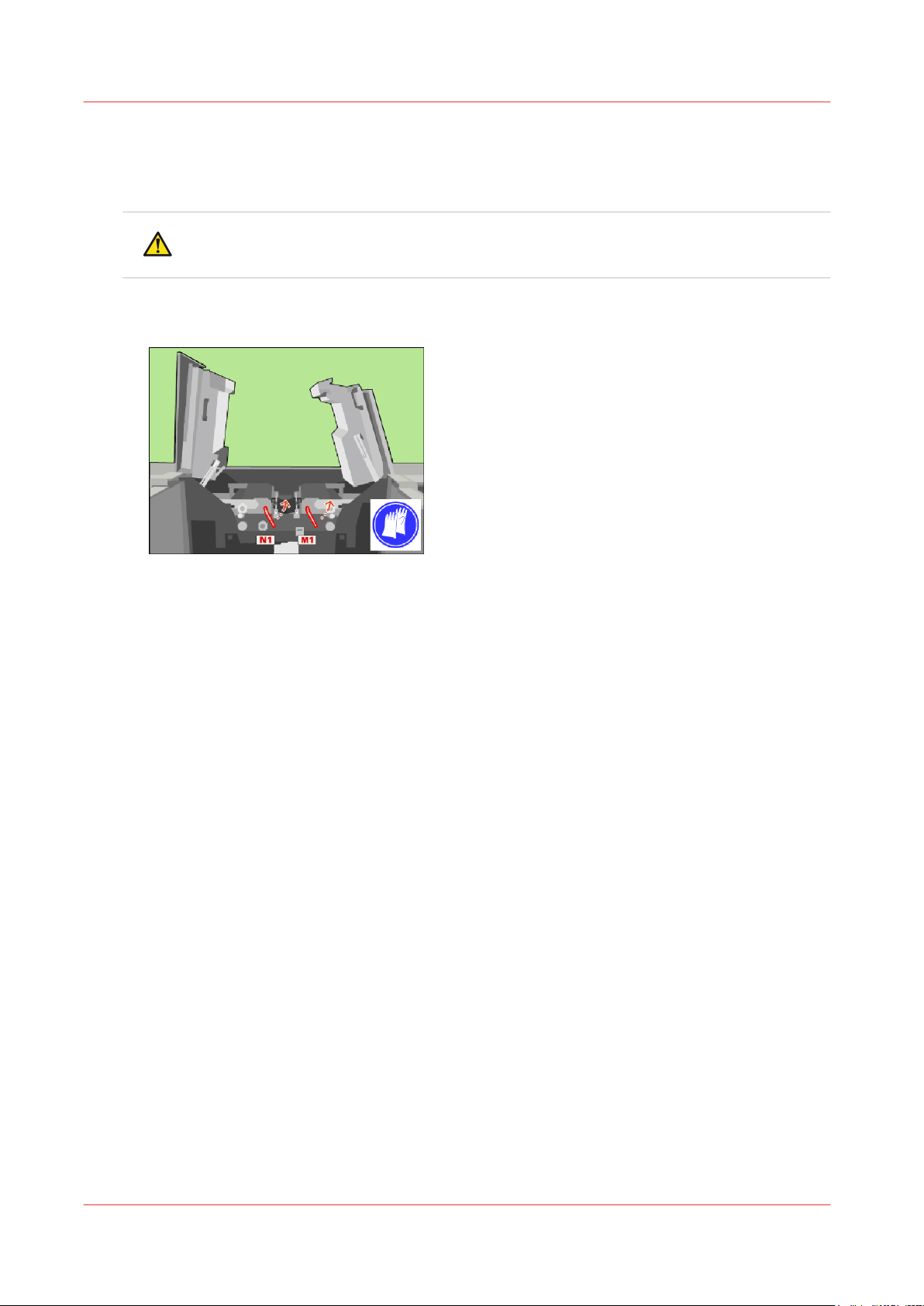
Unlock the clean units
Unlock the clean units
Procedure
CAUTION
Hot area. Use heat-resistant gloves.
Use the service key to turn N1 counter-clockwise.
1.
Use the service key to turn M1 counter-clockwise.
2.
[96] Unlock the clean units
Chapter 3 - Maintenance tasks - Level 2
76
Océ VarioPrint 6000 line
Page 77
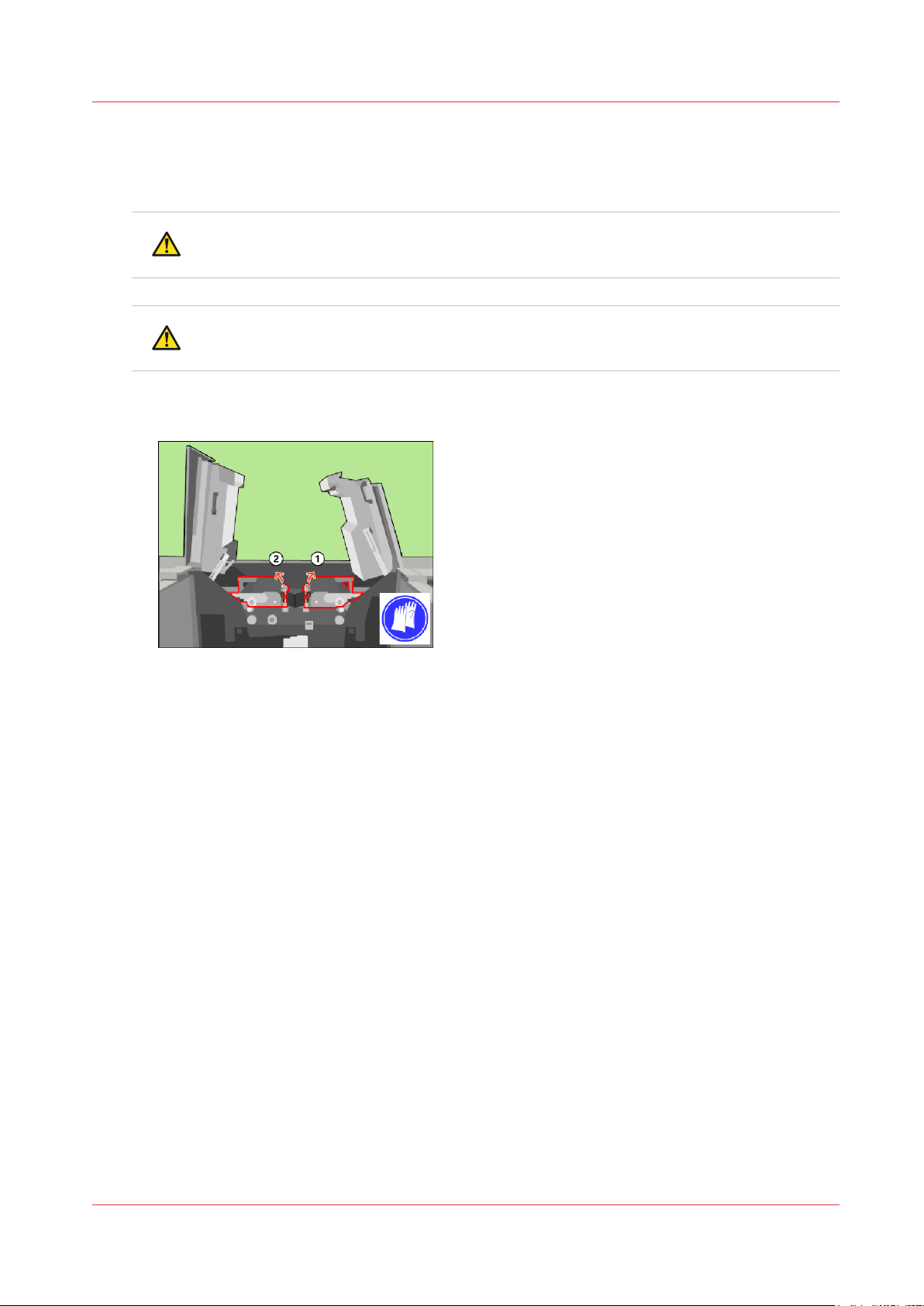
Lift the clean units
Procedure
CAUTION
Hot area. Use heat-resistant gloves.
CAUTION
Make sure that both clean units are locked in the upper position.
Use the red handle to lift the right-hand clean unit to the upper position (1).
1.
Use the red handle to lift the left-hand clean unit to the upper position (2).
2.
Lift the clean units
[97] Lift the clean units
Océ VarioPrint 6000 line
Chapter 3 - Maintenance tasks - Level 2
77
Page 78
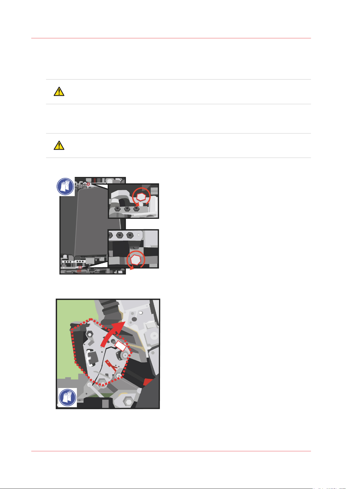
Lift the TTF units
Lift the TTF units
Procedure
CAUTION
Hot area. Use heat-resistant gloves.
When the optional light-weight media module is installed, you have to remove the air guidance
1.
unit before you can lift the TTF units.
Remove the air guidance unit
CAUTION
Hot area. Use heat-resistant gloves.
Use socket wrench 10 to loosen the two bolts of the right-hand TTF Unit.
2.
on page 95.
Lift the right-hand TTF unit, using the metal bar at the front side.
3.
Chapter 3 - Maintenance tasks - Level 2
78
Océ VarioPrint 6000 line
Page 79
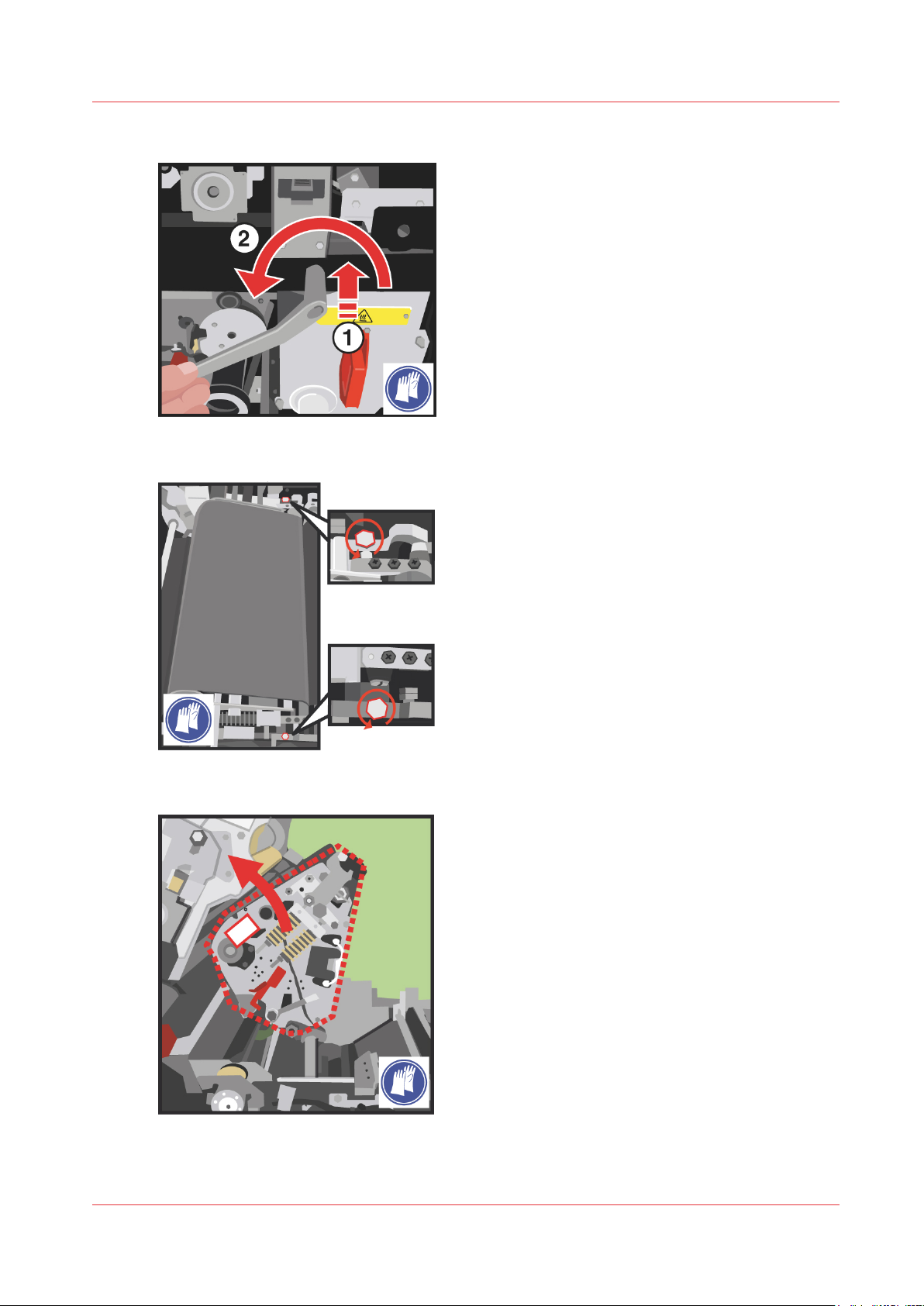
Push the service key at the indicated location inside and turn it counter-clockwise.
4.
Use socket wrench 10 to loosen the two bolts of the left-hand TTF Unit.
5.
Lift the TTF units
Lift the left-hand TTF unit, using the metal bar at the front side.
6.
Océ VarioPrint 6000 line
Chapter 3 - Maintenance tasks - Level 2
79
Page 80
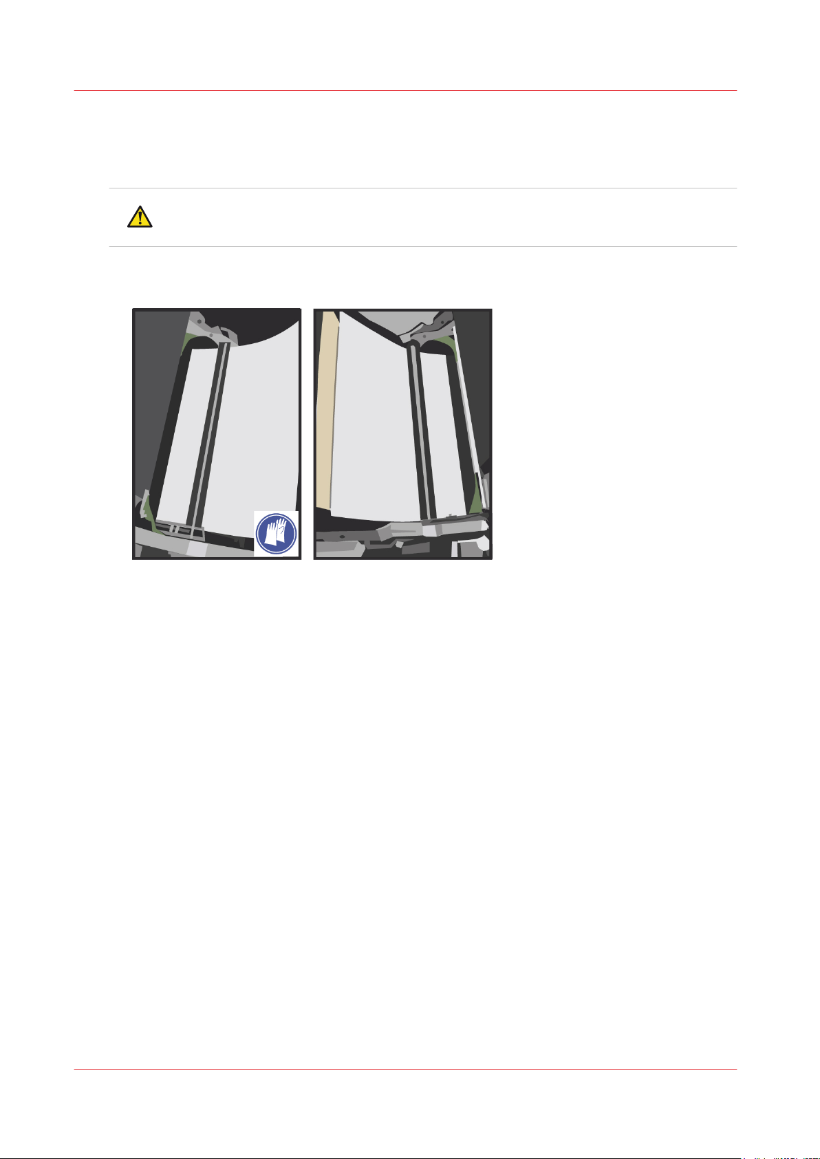
Prepare for cleaning
Prepare for cleaning
Procedure
CAUTION
Hot area. Use heat-resistant gloves.
Put a minimum of 4 layers of paper under the left-hand and the right-hand glue cleaning roller to
1.
protect the OPC.
Chapter 3 - Maintenance tasks - Level 2
80
Océ VarioPrint 6000 line
Page 81
Clean the glue cleaning rollers
CAUTION
Cleaner fluids can cause irritation. Read the Material Safety Data Sheets of the cleaner fluids
before use.
CAUTION
Hot area. Use heat-resistant gloves.
IMPORTANT
Always clean both glue cleaning rollers.
IMPORTANT
For all cleaning actions, apply a small amount of cleaner fluid on an offset pad.
Depending on the kind of pollution, you may require different cleaner solutions.
Procedure
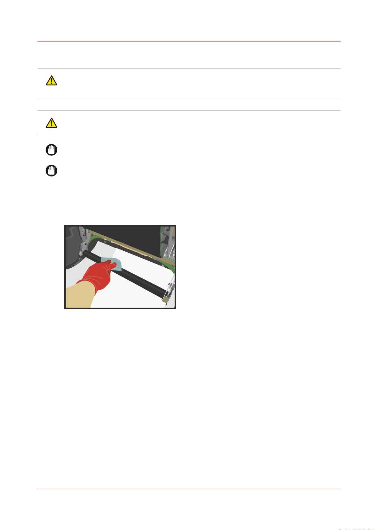
Clean the glue cleaning rollers with Océ Cleaner K.
1.
Clean the glue cleaning rollers
When the rollers contain white pollution (probably PE-wax), clean the rollers with Océ Cleaner T.
2.
If the rollers show extreme pollution,
3.
• clean the rollers with Océ Cleaner P first and then,
• clean the rollers with Océ Cleaner T.
Clean the rollers again with Océ cleaner K to finish the cleaning procedure.
4.
Carefully remove all the protective paper.
5.
Océ VarioPrint 6000 line
Chapter 3 - Maintenance tasks - Level 2
81
Page 82
B
Screw (POS 63)
Spring
Cable guide
A
A
A
1 2
Close the TTF units
Close the TTF units
Procedure
CAUTION
Hot area. Use heat-resistant gloves.
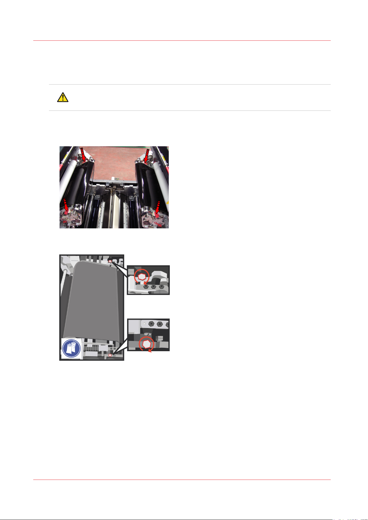
Carefully push the left-hand TTF unit down, using the red press plates.
1.
When the red press plates are not present, carefully push on the indicated area to close the lefthand TTF unit.
Use socket wrench 10 to tighten the two bolts of the left-hand TTF Unit.
2.
Chapter 3 - Maintenance tasks - Level 2
82
Océ VarioPrint 6000 line
Page 83
B
Screw (POS 63)
Spring
Cable guide
A
A
A
1 2
Close the TTF units
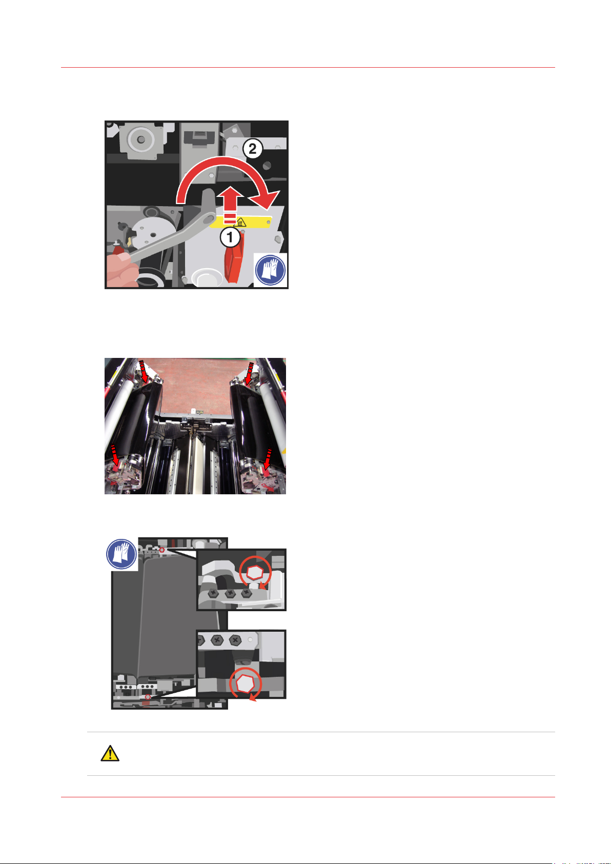
Push the service key at the indicated location inside and turn it clockwise to put the tension on the
3.
TTF belt.
Carefully push the right-hand TTF unit down, using the red press plates.
4.
When the red press plates are not present, carefully push on the indicated area to close the righthand TTF unit.
5.
Océ VarioPrint 6000 line
Use socket wrench 10 to tighten the two bolts of the right-hand TTF Unit.
CAUTION
Hot area. Use heat-resistant gloves.
Chapter 3 - Maintenance tasks - Level 2
83
Page 84

Close the TTF units
When the optional light-weight media module was installed, install the air guidance unit again.
6.
Install the air guidance unit
on page 97.
Chapter 3 - Maintenance tasks - Level 2
84
Océ VarioPrint 6000 line
Page 85
Lower the clean units
Procedure
IMPORTANT
Make sure that the clean units are in the lowest position.
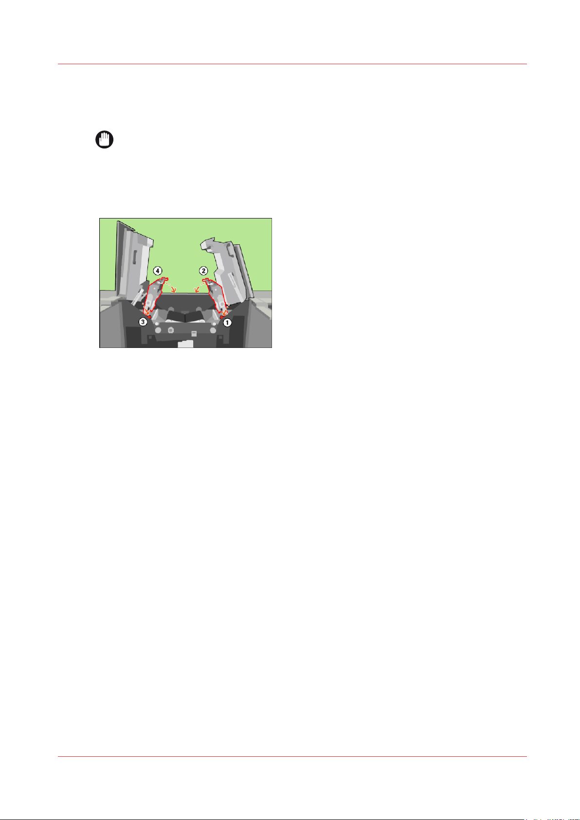
Lift the right-hand clean unit and push the red handle to unlock the locking mechanism (1).
1.
Lower the right-hand clean unit into the locked position (2).
2.
Lift the left-hand clean unit and push the red handle to unlock the locking mechanism (3).
3.
Lower the left-hand clean unit into the locked position (4).
4.
Lower the clean units
[98] Lower the clean units
Océ VarioPrint 6000 line
Chapter 3 - Maintenance tasks - Level 2
85
Page 86
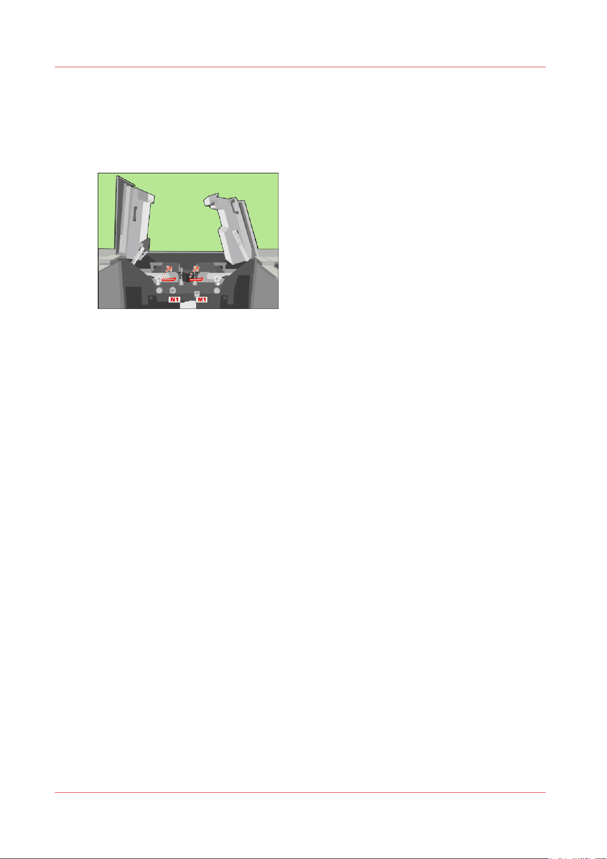
Lock the clean units
Lock the clean units
Procedure
Use the service key to turn N1 clockwise.
1.
Use the service key to turn M1 clockwise.
2.
[99] Lock the clean units
Chapter 3 - Maintenance tasks - Level 2
86
Océ VarioPrint 6000 line
Page 87
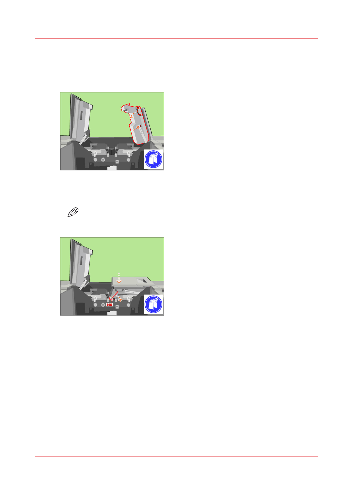
Close the covers
Procedure
Unlock and lower the right-hand inner cover.
1.
[100] Close the right-hand inner cover
Only when the M0 lock is present, push down the inner right-hand cover. Turn the M0 lock with
2.
the service key clockwise to lock the inner right-hand cover.
Close the covers
NOTE
Remove the service key.
[101] When the M0 lock is present, lock the inner right-hand cover
Lift the right-hand top cover to the upper position (1).
3.
Océ VarioPrint 6000 line
Chapter 3 - Maintenance tasks - Level 2
87
Page 88
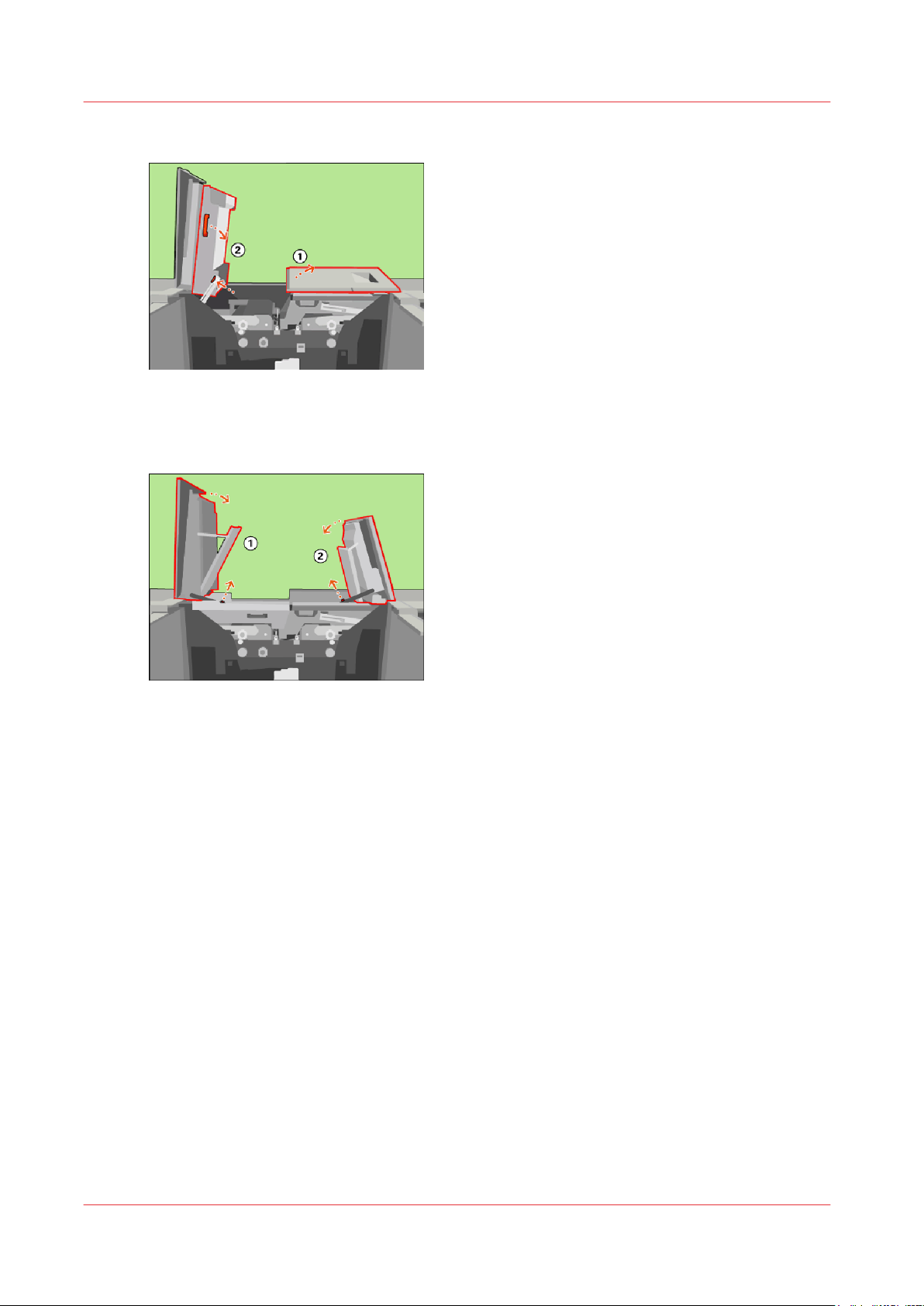
Close the covers
Unlock and lower the left-hand inner cover (2).
4.
[102] Close the left-hand inner cover
Close the left-hand top cover (1).
5.
Close the right-hand top cover (2).
6.
[103] Close the top covers
Chapter 3 - Maintenance tasks - Level 2
88
Océ VarioPrint 6000 line
Page 89
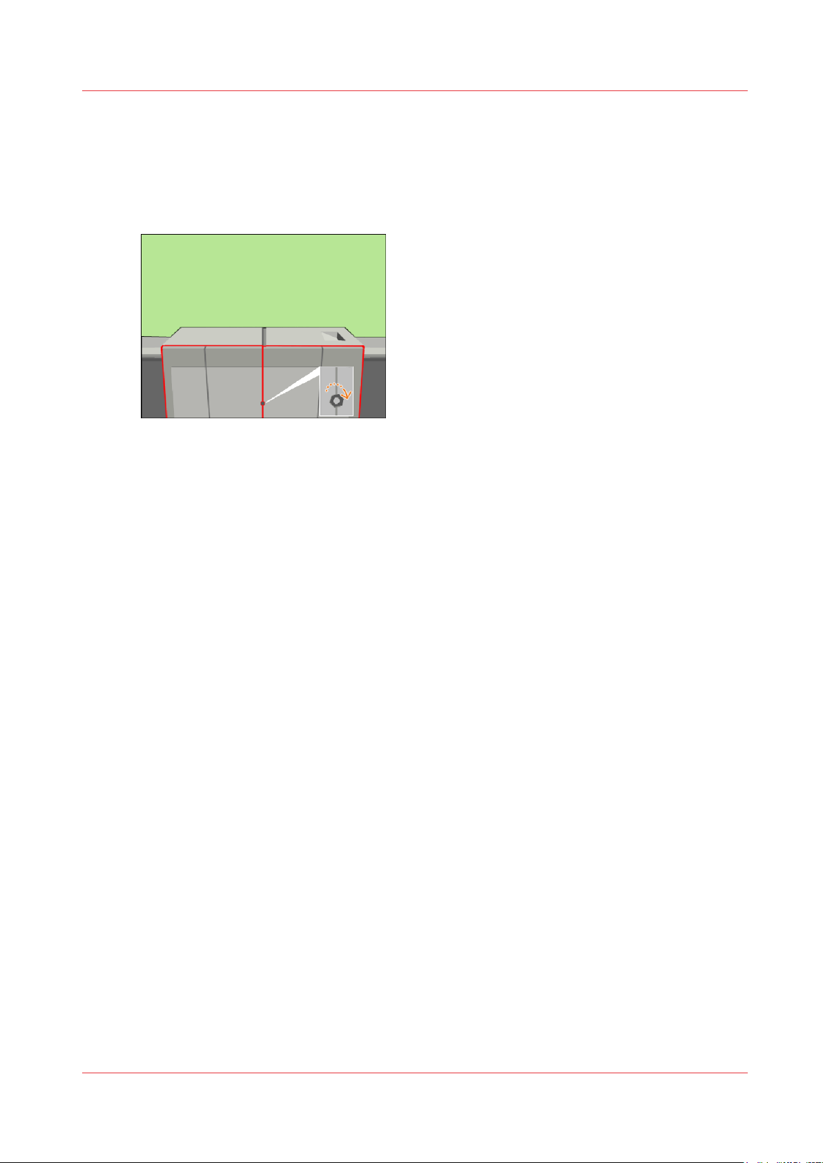
Finish the maintenance task
Procedure
Close the front doors.
1.
Use socket wrench 10 to tighten the bolt of the front doors.
2.
[104] Close the front doors
Press [Stop] to close the maintenance screen. The machine is turned on.
3.
Finish the maintenance task
Océ VarioPrint 6000 line
Chapter 3 - Maintenance tasks - Level 2
89
Page 90

Finish the maintenance task
Chapter 3 - Maintenance tasks - Level 2
90
Océ VarioPrint 6000 line
Page 91

Chapter 4
Optional light-weight media module
Page 92
1x
Check the filter
Check the filter
Introduction
This procedure is only intended for key operators who received the special maintenance training.
Action
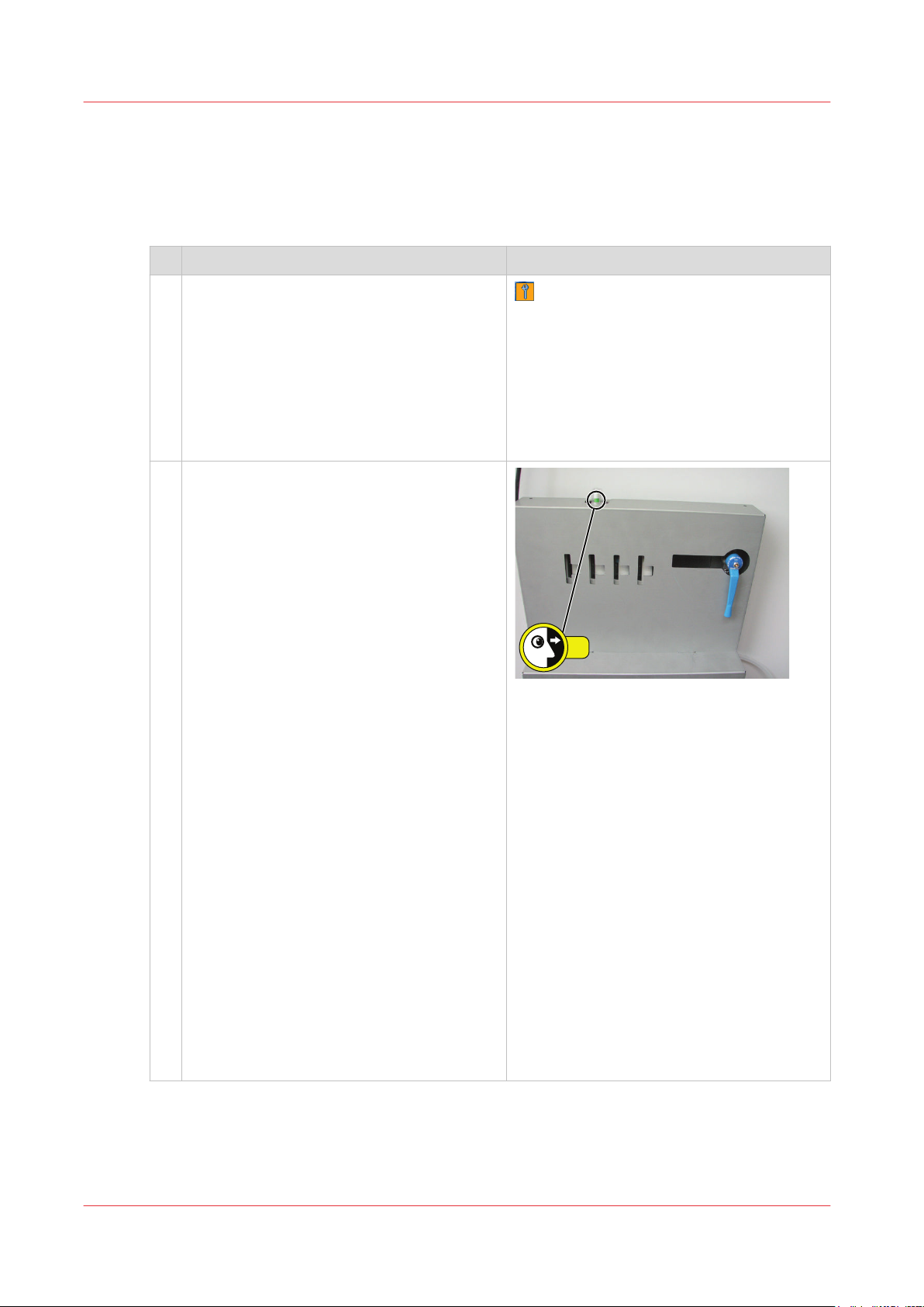
1 You can only check the filter when the sys-
tem is printing or when the system indicates
that you should check the air filters. This is
indicated by the orange maintenance icon.
When the system is not printing or the system is not performing the maintenance task
described below, the indicator of the filter is
green, independently of the status of the filter.
2 Check the indicator of the filter of the light-
weight media module at the rear side of the
machine.
You can check the indicator when the maintenance icon is orange but you can also
check the indicator when the maintenance
indicator is not displayed.
• Maintenance icon is orange:
1. When the maintenance icon is orange,
go to the maintenance task [Check the
status of the air filters].
2. Start the maintenance task.
3. Check the indicator at the rear side of
the machine.
• When the indicator is green, do not
replace the filter.
• When the indicator is red, replace
all 4 filters.
4. Answer the question about the replacement of the air filters.
• Maintenance icon is not displayed:
1. Make sure that the system is printing,
otherwise the indicator is green, independently of the status of the filter.
2. Check the indicator at the rear side of
the machine.
• When the indicator is green, do not
replace the filter.
• When the indicator is red, replace
all 4 filters.
See below.
Chapter 4 - Optional light-weight media module
92
Océ VarioPrint 6000 line
Page 93
Replace the filter
1x
2x
30°
1x
Introduction
This procedure is only intended for key operators who received the special maintenance training.
Action
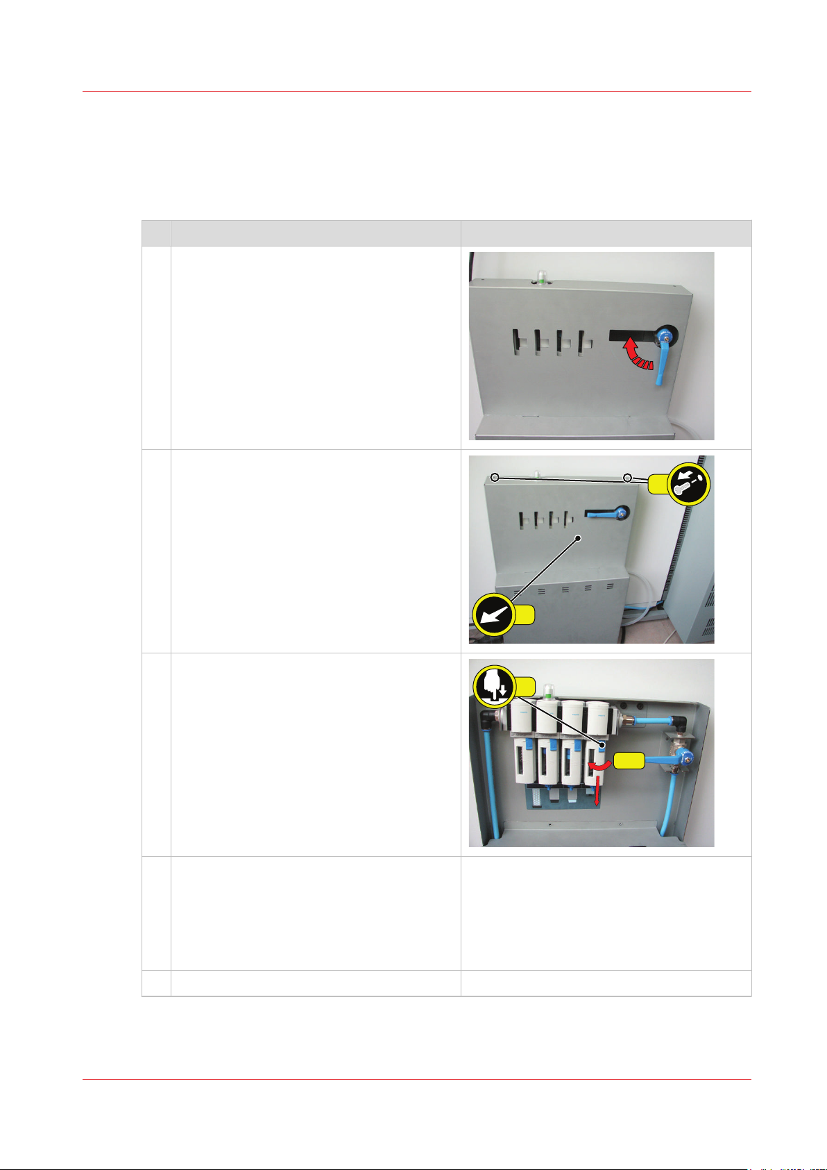
1 Move the handle up to shut off the incoming
air.
2 Remove the upper cover of the filter unit.
1. Remove the two screws.
2. Remove the upper cover.
Replace the filter
3 Remove all 4 filters.
1. Push the blue locking down.
2. Rotate the cover clockwise about 30°.
You must use force.
3. Pull the cover downwards.
4. Remove the filter.
4 Install 4 new filters.
1. Install the new filter.
2. Install the cover upwards.
3. Rotate the cover anticlockwise about 30°.
You must use force.
4. Push the blue locking up.
5 Install the upper cover of the filter unit.
4
Océ VarioPrint 6000 line
Chapter 4 - Optional light-weight media module
93
Page 94
Replace the filter
Action
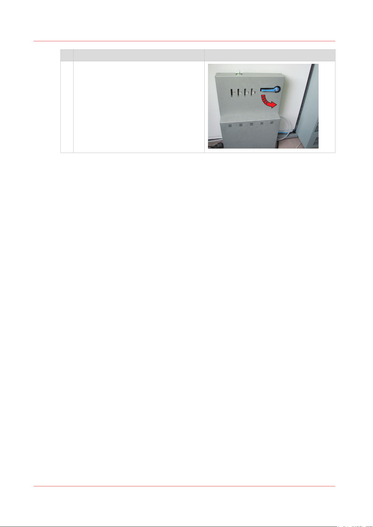
6 Move the handle down to switch on the in-
coming air.
Chapter 4 - Optional light-weight media module
94
Océ VarioPrint 6000 line
Page 95
Remove the air guidance unit
Introduction
This procedure is only intended for key operators who received the special maintenance training.
When to do
Use this procedure to remove the air guidance unit to access the TTF, for example when you
need to remove sheets in the TTF.
Action
Remove the air guidance unit
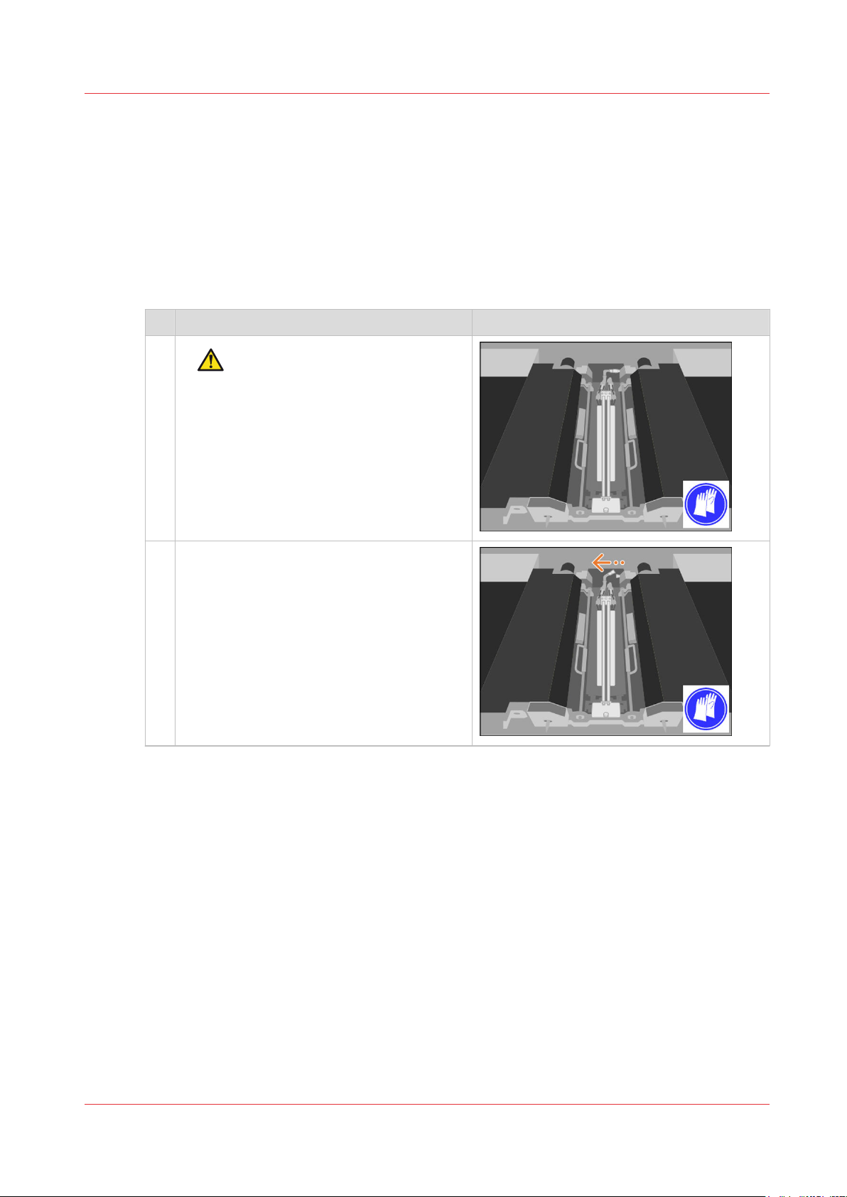
1 [Disconnect the connector of the air supply
hose from the air guidance unit.]
CAUTION
The TTF area can be hot.
4
Océ VarioPrint 6000 line
Chapter 4 - Optional light-weight media module
95
Page 96
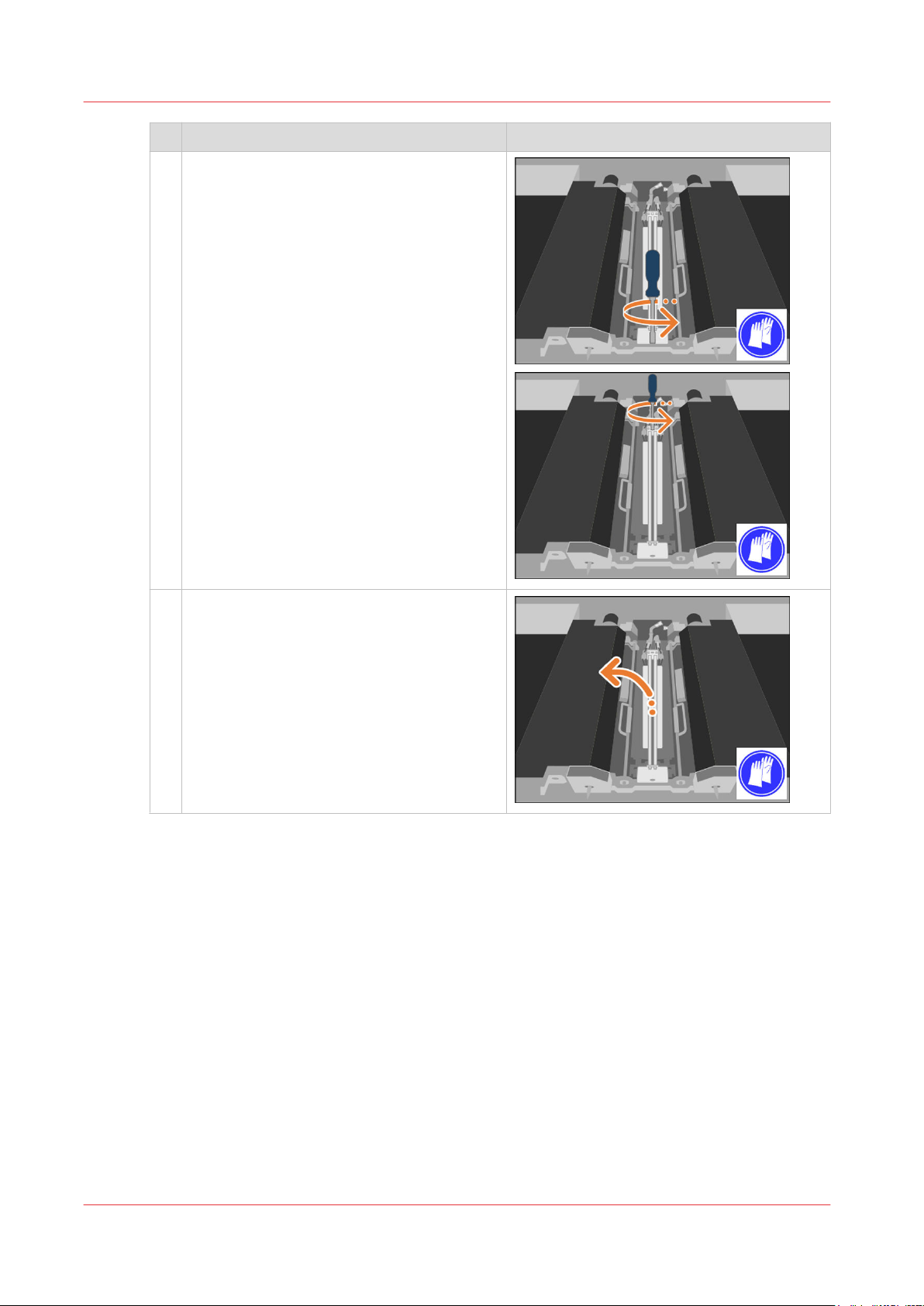
Remove the air guidance unit
Action
2 [Unscrew the two bolts that attach the unit
to the machine.]
One bolt at the front side and one bolt at the
rear side.
3 [Lift the air guidance unit and put it aside on
a safe place.]
Chapter 4 - Optional light-weight media module
96
Océ VarioPrint 6000 line
Page 97
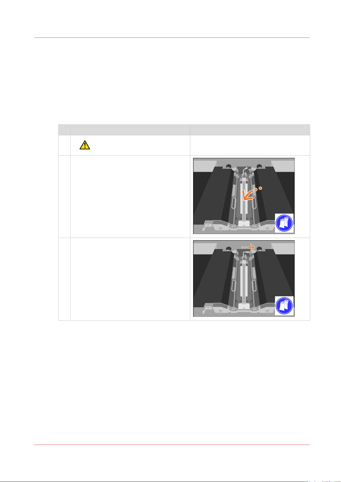
Install the air guidance unit
Introduction
This procedure is only intended for key operators who received the special maintenance training.
When to do
After you performed a maintenance action in the TTF area, you must install the air guidance unit
again.
Action
Install the air guidance unit
1 [Take and place back the air guidance unit.]
2 [Connect the connector of the air supply
hose to the air guidance unit.]
CAUTION
The TTF area can be hot.
Océ VarioPrint 6000 line
Chapter 4 - Optional light-weight media module
4
97
Page 98
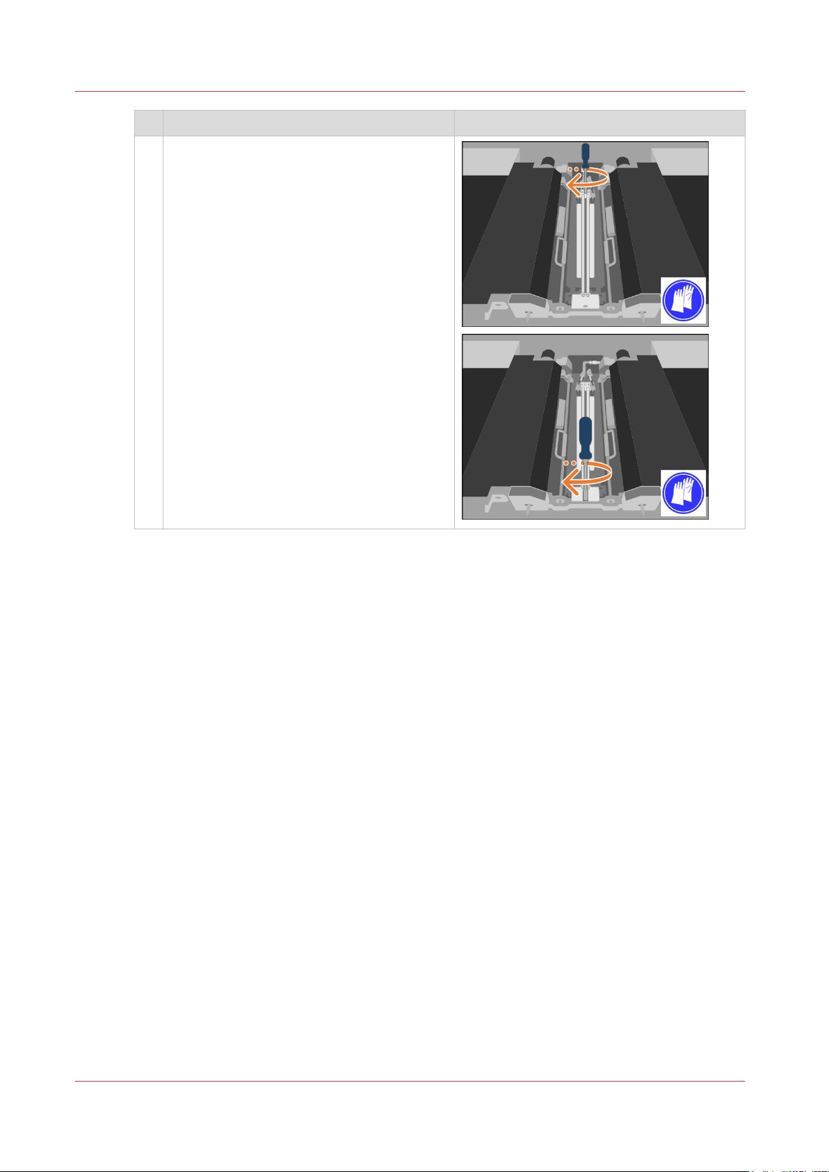
Install the air guidance unit
Action
3 [Screw the two bolts to attach the air guid-
ance unit to the machine.]
One bolt at the rear side and one bolt at the
front side.
Chapter 4 - Optional light-weight media module
98
Océ VarioPrint 6000 line
Page 99

Index
Index
A
Air guidance unit
install.................................................................97
remove..............................................................95
Available documentation.........................................8
C
Check
filter................................................................... 92
Clean
Frame unit.........................................................30
Glue cleaning rollers..................................73, 81
OPC belt (left)............................................. 61, 63
OPC belt (right)...........................................67, 69
Clean unit
Left.....................................................................34
Right..................................................................36
Content of the manuals............................................8
D
Determine the required maintenance...................12
G
Glue cleaning rollers........................................ 73, 81
I
Level 1.................................................................
Level 2.................................................................9
Maintenance levels...................................................9
Maintenance screen................................................. 9
O
OPC belt
Left.....................................................................61
Right..................................................................67
R
Remove
air guidance unit.............................................. 95
Preheat unit...................................................... 48
Sheet cleaners..................................................19
Spiral cleaners..................................................21
Remove sheets
Inner covers......................................................43
Interface module.............................................. 40
Preheat unit...................................................... 50
Process modules..............................................40
Registration unit...............................................46
Top cover..........................................................42
Replace
filter................................................................... 93
Sheet cleaners..................................................14
Spiral cleaners..................................................14
9
Install
air guidance unit.............................................. 97
Preheat unit...................................................... 52
Sheet cleaners..................................................25
Spiral cleaners..................................................24
L
Light-weight media module
air guidance unit........................................ 95, 97
filter............................................................. 92, 93
Lock
Clean unit (left).................................................34
Clean unit (right).............................................. 36
M
Maintenance
Océ VarioPrint 6000 line
S
Sheet cleaners........................................................ 14
Solve paper jam in hot areas.................................12
Spiral cleaners........................................................ 14
99
Page 100

Index
100
Océ VarioPrint 6000 line
 Loading...