

Oce ProCut 2500 L, ProCut 1600 XL, ProCut 1600 XXL, ProCut 1600 XXXL, ProCut 2500 M User Manual
...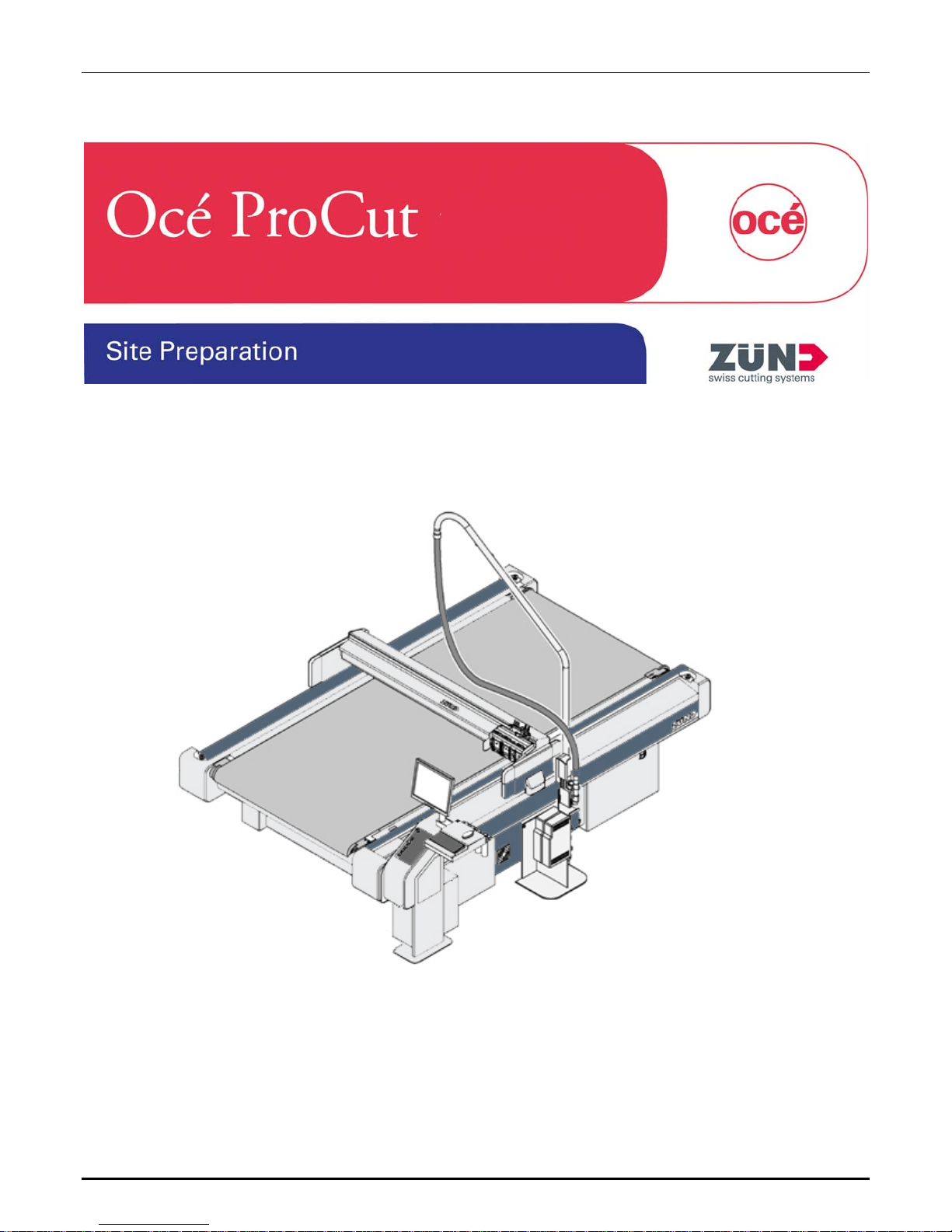
Océ ProCut 1600, 2500, and 3200 Series Cutters
Revision E – July 23, 2010

Océ ProCut Site Prep
Océ Display Graphics Systems
Océ ProCut Site Preparation Guide - Revision: E ii
© 2010 All Rights Reserved
Part Number: 3010108370

Océ ProCut Site Prep
Table of Contents
Table of Figures...................................................................................................................... iv
Preface...................................................................................................................................... v
Copyright ....................................................................................................................................v
Document Summary...................................................................................................................v
Product Support, Documentation, and Service ..........................................................................v
Introduction.............................................................................................................................. 1
Considerations:...........................................................................................................................1
System Requirements............................................................................................................. 2
Receiving the Océ ProCut ..........................................................................................................2
Crate Dimensions and Weight....................................................................................................3
Facility Requirements ............................................................................................................. 5
Floor Loading..............................................................................................................................5
Electrical Placement ...................................................................................................................5
Location Dimensions ..................................................................................................................5
Electrical Requirements..............................................................................................................6
400V Electrical connection .........................................................................................................6
200V Electrical connection .........................................................................................................7
Ground Fault Requirements .......................................................................................................8
Router Vacuum Cleaner: ............................................................................................................9
Dust Extraction: ..........................................................................................................................9
Installation / Training............................................................................................................. 11
Specifications ........................................................................................................................ 12
Machine Dimensions and Weight: ............................................................................................12
Floor Conditions .......................................................................................................................15
Environment .............................................................................................................................16
Safety Information ....................................................................................................................16
Minimum PC Requirements......................................................................................................16
Océ ProCut Macintosh Prepress Client ................................................................................16
Océ ProCut Windows Prepress Client..................................................................................16
Océ ProCut Windows Server & ONYX RIP ..........................................................................17
Windows Cut Client...............................................................................................................17
Check list................................................................................................................................18
Océ ProCut Site Preparation Guide - Revision: E iii

Océ ProCut Site Prep
List of Tables
Table 1: Crate Dimensions and Weight ...................................................................................................4
Table 2: Cutter Extension Crate Dimensions and Weights.......................................................................4
Table 3: Location Dimensions..................................................................................................................5
Table 4: Power Consumption and Variance ............................................................................................6
Table 5: Electrical Connections with 1-9kW Vacuum Turbine/Generator ................................................6
Table 6: Power Consumption and Variance ............................................................................................7
Table 7: Electrical Connections with 1-9kW Vacuum Turbine/Generator ................................................7
Table 8: Electrical Connections with 2.2/2.55kW Vacuum Pumps ..........................................................8
Table 9: Electrical Connections with 2.2/2.55kW Vacuum Pumps ..........................................................8
Table 10: Vacuum Cleaner Specifications...............................................................................................9
Table 11: Compressed Air .....................................................................................................................10
Table 12: 1600 Series Machine Dimensions and Weight ......................................................................12
Table 13: 2500 Series Machine Dimensions and Weight ......................................................................13
Table 14: 3200 Series Machine Dimensions and Weight ......................................................................14
Table 15: Cutter Extension Dimensions and Weights............................................................................15
Table 16: Floor Conditions.....................................................................................................................15
Table 17: Environment...........................................................................................................................16
Table of Figures
Figure 1: Shipping Crate..........................................................................................................................2
Figure 2: 400V Electrical Connection.......................................................................................................6
Figure 3: 200V Electrical Connection.......................................................................................................7
Figure4: 400V Electrical Connection........................................................................................................8
Figure 5: 200V Electrical Connection.......................................................................................................8
Océ ProCut Site Preparation Guide - Revision: E iv

Océ ProCut Site Prep
Preface
Copyright
© 2010 Océ Display Graphics Systems. All rights reserved.
This document contains information proprietary to Océ, to its subsidiaries, or to third parties to
which Océ may have a legal obligation to protect such information from unauthorized disclosure,
use or duplication. Any disclosure, use, or duplication of this document or of any of the information
contained herein for other than the specific purpose for which it was disclosed is expressly
prohibited, except as Océ may otherwise agree to in writing. Due to continuing research and
product improvements, features or product specifications may change at any time without notice.
Document Summary
Date Revision Summary
Oct. 27, 2008 Revision A Initial release.
Dec 15, 2008 Revision B Added harmonics and flicker info
Mar 12, 2009 Revision C Added 1600 series and 3200 XXL and XXXL models
Added 1600 M and additional power connections for the use
Jul 29, 2009 Revision D
Jul 11, 2010 Revision E
of a 2.2kW vacuum pump.
Also modified the width of the 1600 series to include the
Router Option (B3).
Added Cutter Extension specifications.
Updated Compressed Air specifications
Product Support, Documentation, and Service
For further information on documentation and support for your Océ ProCut Cutter or for information
on other Océ Display Graphics Systems products visit our web site:
Web: http://www.dgs.oce.com
Comments on this manual? email to: DGSTechnical.Writer@oce.com
Océ maintains a comprehensive support structure for its customers. Upon installation of your cutter,
you will be provided with the name of the sales and service office responsible
Océ ProCut Site Preparation Guide - Revision: E v

Océ ProCut Site Prep
Introduction
This document contains information that will be helpful to you in determining the final location for
the cutter, transporting the cutter to its final location, and all specifications for power, space, and
environmental conditions required for the Océ ProCut manufactured by Zünd.
Considerations:
Determine where the cutter system will be located. Any and all construction measures must be
completed before the cutter system is installed.
Location of the cutter should not be in close proximity to printers due to the dust and particle
generation from this device.
Mark out the installation location to scale using adhesive tape. See the section "Technical data" for
the exterior measurements.
Ensure that the installation location meets the relevant requirements: - Room size - Subsurface Temperature - Cleanliness (free of dust and dirt)
Ensure that there are connections for electricity and compressed air at the installation location and
that these meet the required specifications.
Check whether it is possible to transport the cutter to the installation location. If necessary, arrange
for a forklift or mobile crane to be available on the installation day.
Examine the route to the desired location of the Cutter.
The following guidelines will help you determine the route and final location of your cutter:
• Ideally, the crates should be transported to the installation location using a forklift truck or
mobile crane. However, you can also transport the crates over short distances using a pallet
jack with long forks. The installation guide contains detailed information (center of gravity,
requirements) about transporting the crates.
• Determine a route to the installation location. Ensure that this route is as short as possible
and that it is sufficiently wide.
• Check the route for any obstacles (narrow passages, doors, railings, radiators, steps).
Remove these if required.
• Be aware of the size and weight of the cutter and be sure the floor of the route can support
the weight of the crates and forklift!
• This route must be wide and high enough to allow free movement of the cutter crate,
including corners and bends.
• For crate dimensions, see: section 5 Technical Data
Confirm a delivery/installation date.
• A well-prepared installation saves time and money for everyone involved!
Océ ProCut Site Prep
System Requirements
Receiving the Océ ProCut
Packed in its crate, the Océ ProCut can withstand normal vibrations from road or air travel. Severe
shock, however, may damage the components within the machine. Document all visible damage to
the packaging immediately upon delivery. Verify that the shipper records this damage on the
delivery bill of lading and report to your Océ Operating Company.
Only Océ trained service technicians should only open crates. Internal parts can be damaged if
mishandled.
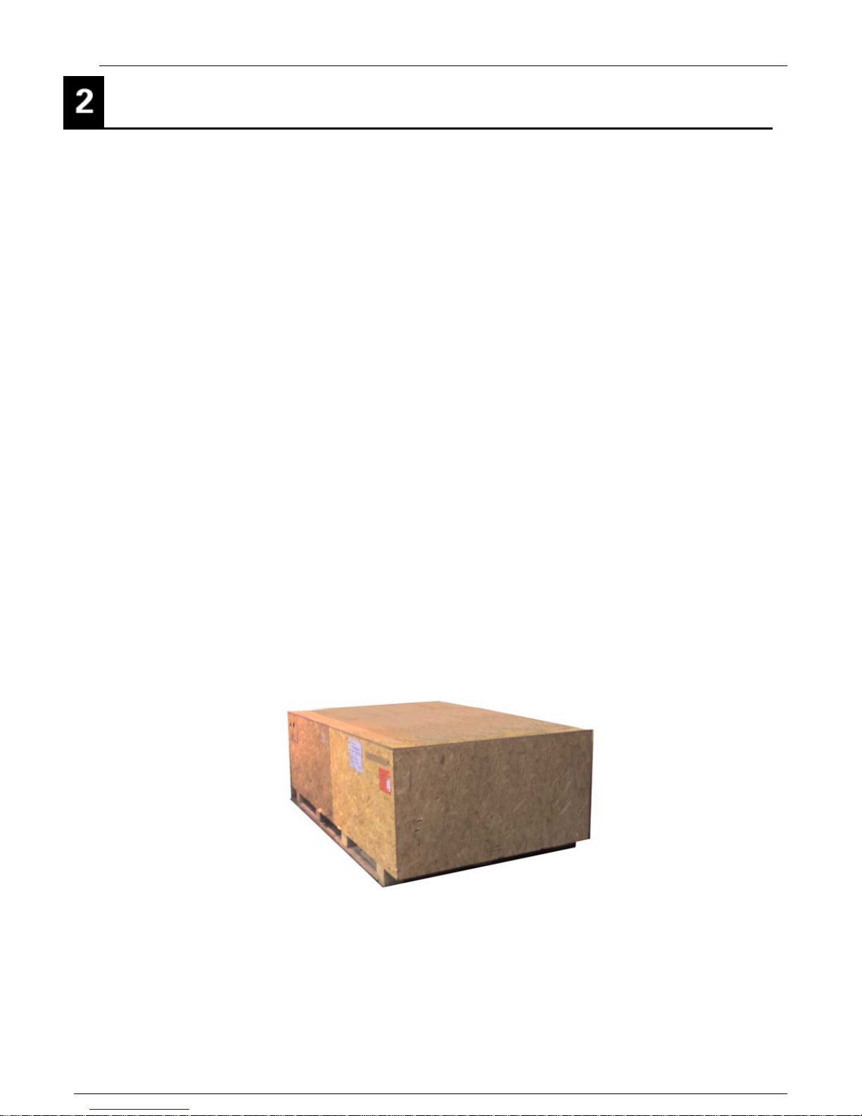
The Océ ProCut is typically shipped in three wooden crates and one pallet. See Dimensions and
Weight. Due to the weight and delicate nature of the cutter it is essential to have the proper
equipment available for handling and moving the shipping crates.
Important: The majority of the installation will be carried out by a Océ trained Service
Technician. However, additional support is required for some tasks (transportation,
moving heavy parts, holding parts in place during assembly etc). The Océ Service
Technician should arrange for an assistant to be available during the assembly
phase.
Because of the weight of each crate, we recommend using a forklift to prevent personal injury
and/or damage to the equipment. If you do not have a forklift, you can use one palette jack on
smaller crates and two palette jacks on larger crates.
If an Océ trained technician is not present for the delivery of the system, then the transport crates
are not to be opened and the machine must not be unpacked. This must be kept in a dry place from
the time of delivery until the arrival of the technician.
Storage temperature: -20º / 55º C (-4° / 126° F)
Océ ProCut Site Preparation Guide - Revision: E 2
Figure 1: Shipping Crate

Océ ProCut Site Prep
Crate Dimensions and Weight
1600 M
Crate 1:
Crate 2:
1600 XL
Crate 1: Basic unit 4250x1580x710 720
Crate 2: Basic unit 3790 x 1580 x 970 1080
1600 XXL
Crate 1: Basic unit 4250 x 1580 x 710 750
Crate 2: Basic unit 3790 x 1580 x 1220 1180
1600 XXXL
Crate 1: Basic unit 4250 x 1580 x 710 780
Crate 2: Basic unit 3790 x 1580 x 1220 1280
2500 L
Basic unit
Basic unit
Largest part (unpackaged)
Largest part (unpackaged)
Largest part (unpackaged)
Largest part (unpackaged)
Crate Dimensions [mm] In Crate [kg]
2260 x 1550 x 940 650 kg
3080 x 1550 x 600 900 kg
2512 x 300 x 300 100
Crate Dimensions [mm] In Crate [kg]
2512 x 300 x 300 100
Crate Dimensions [mm] In Crate [kg]
2512 x 300 x 300 100
Crate Dimensions [mm] In Crate [kg]
2512 x 300 x 300 100
Crate Dimensions [mm] In Crate [kg]
Crate 1: Basic unit 3550 x 1580 x 700 720
Crate 2: Basic unit 3160 x 1580 x 940 1030
2500 M
Crate 1: Basic unit 3550 x 1580 x 700 700
Crate 2: Basic unit 3160 x 1580 x 940 880
3200 L
Crate 1: Basic unit 4250 x 1580 x 710 750
Crate 2: Basic unit 3790 x 1580 x 970 1250
3200 XL
Crate 1: Basic unit 4250 x 1580 x 710 780
Crate 2: Basic unit 3790 x 1580 x 970 1350
3200 XXL
Crate 1: Basic unit 4250x1580x710 820
Crate 2: Basic unit 3790x1580x1220 1550
3200 XXXL
Largest part (unpackaged)
Largest part (unpackaged)
Largest part (unpackaged)
Largest part (unpackaged)
Largest part (unpackaged)
3412 x 300 x 300 115
Crate Dimensions [mm] In Crate [kg]
3412 x 300 x 300 115
Crate Dimensions [mm] In Crate [kg]
4112 x 300 x 300, 130
Crate Dimensions [mm] In Crate [kg]
4112 x 300 x 300 130
Crate Dimensions [mm] In Crate [kg]
4112 x 300 x 300 130
Crate Dimensions [mm] In Crate [kg]
Crate 1: Basic unit 4250 x 1580 x 710 850
Crate 2: Basic unit 3790 x 1580 x 1220 1700
Océ ProCut Site Preparation Guide - Revision: E 3
Largest part (unpackaged)
4112 x 300 x 300 130

Océ ProCut Site Prep
All Models
Pallet 1: Vacuum Generator 1200 x 800 x 970 140
Pallet 2: Workstation 2684 x 850 x 550 120
Note: Models ordered with a vacuum cleaner will ship with the workstation inside a crate.
Table 1: Crate Dimensions and Weight
Crate Dimensions [mm] In Crate [kg]
Cutter Extension Option Crate Dimensions and Weight
Cutter Extension
Crate Dimensions [mm] Weight [kg]
CE2500
2500 L
2500 M
Cutter Extension
2690 x 890 x 560 190
2690 x 890 x 560 165
Crate Dimensions [mm] Weight [kg]
CE3200
3200 L
3200XL
3200 2XL
3200 3XL
3200 x 890 x 560 230
3200 x 890 x 560 230
3790 x 890 x 560 290
3790 x 890 x 560 305
Table 2: Cutter Extension Crate Dimensions and Weights
Océ ProCut Site Preparation Guide - Revision: E 4

Océ ProCut Site Prep
Facility Requirements Facility Requirements
Determine where the cutter system will be located in advance of the installation. Mark this with
Determine where the cutter system will be located in advance of the installation. Mark this with
adhesive tape so that you can confirm the dimensions. Ensure that there is a gap of at least 1 meter
adhesive tape so that you can confirm the dimensions. Ensure that there is a gap of at least 1 meter
to the nearest wall all around the machine to allow access by operating and servicing personnel.
to the nearest wall all around the machine to allow access by operating and servicing personnel.
Two meters at the front end of the system will make media handling much easier.
Two meters at the front end of the system will make media handling much easier.
If the delivery includes a router option, the room must be at least 3 m high. See location
If the delivery includes a router option, the room must be at least 3 m high. See location
Dimensions below for specific model requirements.
Dimensions below for specific model requirements.
Check the room temperature and humidity. Be certain that the environment will meet or exceed the
Check the room temperature and humidity. Be certain that the environment will meet or exceed the
requirements all year long.
requirements all year long.
Provide supports with sufficient stability if the difference in height over the entire installation surface
Provide supports with sufficient stability if the difference in height over the entire installation surface
is greater than 2 cm.
is greater than 2 cm.
Floor Loading Floor Loading
The subsurface for the machine must be sufficiently level and stable. The floor in the operational
The subsurface for the machine must be sufficiently level and stable. The floor in the operational
location must have adequate load-carrying capacity and stiffness. Wood framed/constructed floors
location must have adequate load-carrying capacity and stiffness. Wood framed/constructed floors
are not suitable! Solid and level concrete surface is recommended. The difference in height over
are not suitable! Solid and level concrete surface is recommended. The difference in height over
the entire installation surface must be less than 2 cm.
the entire installation surface must be less than 2 cm.
Floor Loading: minimum 800 kg / 1,764 lbs. per square meter Floor Loading: minimum 800 kg / 1,764 lbs. per square meter
Electrical Placement Electrical Placement
If using wall-mounted power outlets, they can be located on either side or rear of the machine.
If using wall-mounted power outlets, they can be located on either side or rear of the machine.
Depending on distance, extension cords may be needed.
Depending on distance, extension cords may be needed.
If using ceiling power drops, they can be place anywhere behind the PC stand but need to be at
If using ceiling power drops, they can be place anywhere behind the PC stand but need to be at
least 20cm away from the side cover to allow for removal of the side covers during service.
least 20cm away from the side cover to allow for removal of the side covers during service.
Location Dimensions Location Dimensions
Model Width Length Height w/router
1600 M 4679 mm 4512mm 3000 mm/118”
1600 XL 5619 mm 4512mm 3200 mm/125”
1600 XXL 6089 mm 4512mm 3200 mm/125”
1600 XXXL 6559 mm 4512mm 3200 mm/125”
2500 L 5149 mm 5412 mm 3200 mm/125”
2500 M 4679 mm 5412 mm 3000 mm/118”
3200 L 5149 mm 6112 mm 3200 mm/125”
3200 XL 5619 mm 6112 mm 3200 mm/125”
3200 XXL 6089 mm 6112 mm 3200 mm/125”
3200 XXXL 6559 mm 6112 mm 3200 mm/125”
Note: A clear distance to the nearest wall etc. of approx. one-meter must be provided and
maintained for operator and service access. The values if the above table includes onemeter clearance on all sides. Two meters at the front end of the system will make media
handling much easier.
Océ ProCut Site Preparation Guide - Revision: E 5
Table 3: Location Dimensions

Océ ProCut Site Prep
Electrical Requirements
This apparatus is intended to be connected to a power network supplied from a high or medium
voltage transformer dedicated to the supply of an installation feeding manufacturing or similar plant.
This apparatus is not intended to be connected to public low-voltage networks. There are two
electrical voltage configurations: 200V or 400V, and two power frequency configurations: 50 Hz or
60 HZ. The configuration of a particular machine is chosen at time of sale based upon local power
specifications.
All cutter models use the 1-9kW Vacuum Generator (also called a Vacuum Turbine), except for the
1600 M, which uses the 2.2/2.5kW vacuum pump
The vacuum generator and optional milling/router spindle each have a frequency converter that is
used to control their variable speed drive motor. If a ground fault interrupter is used, it must be a
meet particular specifications, see Ground Fault Requirements for more details.
Electrical connection – 400 V system with 1-9kW Vacuum Generator
The cutter is connected with one power cord to the power supply system. All other (optional too)
devices are connected to the power box of the cutter.
• 1 power cord is included in the package content with a CEE32 connector
Warning! An electrical hazard exists if an incorrect ground fault interrupter protects the high-
frequency leakage current. See Ground Fault Requirements.
Power
Main supply voltage variance max. 5%
Power consumption - 3 phases max 12.6kW, typical 5.6kW
Table 4: Power Consumption and Variance
Figure 2: 400V Electrical Connection
“A” Cutter Power box Value Unit
Phases 3
Voltage 400 V
Power frequency, pump-depending 50/60 Hz
Power fusing min. 32 A
Wiring 3 phases, L1, L2, L3, N, PE
CEE-Plug 32A
Special-purpose ground fault interrupter required Fusing current:>30mA per converter
Table 5: Electrical Connections with 1-9kW Vacuum Turbine/Generator
Océ ProCut Site Preparation Guide - Revision: E 6

Océ ProCut Site Prep
Electrical connection – 208 V system with 1-9kW Vacuum Generator
The cutter is connected with one power cord to the power main. The vacuum generator is
connected with one power cord to the power main. The Cutter and Vacuum Generator need
separate circuit breakers. All other devices are connected to the power box of the cutter including
any optional equipment.
• 2 power cords are included in the package content. Customer must supplier connectors to
power supply.
Warning! An electrical hazard exists if an incorrect ground fault interrupter protects the high-
frequency leakage current. See Ground Fault Requirements.
Power
Main supply voltage variance max. 10%
Power consumption - 3 phases max 12.6kW, typical 5.6kW
Table 6: Power Consumption and Variance
Figure 3: 200V Electrical Connection
“A” Cutter Power box Value Unit
Phases 3
Voltage 208 V
Power frequency, pump-depending 50/60 Hz
Power fusing min. 16 A
Wiring 3 phases, L1, L2, L3, N, PE
CEE-Plug 30A, 208V, 5 Poles, Walther Electric Type 230 509
Special-purpose ground fault interrupter required Fusing current:>30mA per converter
“B” Vacuum Turbine/Generator Value Unit
Phases 3
Voltage 208 V
Power frequency, pump-depending 50/60 Hz
Power fusing min. 50 A
Wiring 3 phases, L1, L2, L3, N, PE
CEE-Plug 60A, 208V, 5 Poles, Walther Electric Type 261 509
Special-purpose ground fault interrupter required Fusing current:>30mA per converter
Table 7: Electrical Connections with 1-9kW Vacuum Turbine/Generator
Océ ProCut Site Preparation Guide - Revision: E 7

Océ ProCut Site Prep
Electrical connections - 400 V system with 2.2/2.55 kW vacuum pump (1600 M Only)
Comply with national instructions and laws at connection the cutter to the power supply system. The
cutter is connected with one power cord to the power supply system. The vacuum pump is
connected to the power box of the cutter. 1 power cord is included in the package content.
Figure 4: 400V Electrical Connection
“A” Cutter Power box Value Unit
Phases 3
Voltage 400 V
Power frequency, pump-depending 50/60 Hz
Power fusing min. 32 A
Wiring 3 phases, L1, L2, L3, N, PE
CEE-Plug 32A
Table 8: Electrical Connections with 2.2/2.55kW Vacuum Pumps
Electrical connections - 208 V system with 2.2/2.55 kW vacuum pump (1600 M Only
Comply with national instructions and laws at connection the cutter to the power supply system. The
cutter is connected with one power cord to the power supply system. The vacuum pump is
connected to the power box of the cutter. 1 power cord is included in the package content.
Figure 5: 200V Electrical Connection
“A” Cutter Power box Value Unit
Phases 3
Voltage 208 V
Power frequency, pump-depending 50/60 Hz
Power fusing min. 32 A
Wiring 3 phases, L1, L2, L3, N, PE
CEE-Plug 32A
Table 9: Electrical Connections with 2.2/2.55kW Vacuum Pumps
Océ ProCut Site Preparation Guide - Revision: E 8

Océ ProCut Site Prep
Ground Fault Requirements
Electrical rules and regulations and vary from country to country and sometimes even within a
country. A local electrician should be consulted to determine local ground fault requirements.
Some countries require residual current devices (RCD) or residual current circuit breakers (RCCB).
This is an electrical wiring device that disconnects a circuit whenever it detects that electrical
current is not balanced between the phase (“hot” or “live”) conductor and the neutral conductor.
In the United States and Canada, a residual current device is also known as a ground fault circuit
interrupter (GFCI), ground fault interrupter (GFI) or an appliance leakage current interrupter (ALCI).
In Australia they are sometimes known as "safety switches".
If a RCD/GFI is required, the standard general-purpose model may not work with the Océ ProCut
system. The vacuum generator and optional milling/router spindle each have a frequency converter
that is used to control their variable speed drive motor. A frequency converter has a higher than
typical leakage current and may trip a standard GFI (E.g in many areas in Europe the standard RFI
has a fusing current of 10 mA). If local regulations require a GFI, it must have a fusing current > 30
mA per converter.
In a 200V electrical configuration with the milling/router option there are two connections to power
supply system and if an RFI is required, both connections should have an RFI that has a fusing
current of > 30 mA.
(Compatible GFI model - Hager CDH440C or similar).
In a 400V electrical configuration with the milling/router option there is a single connection to the
power supply system and if an RFI is required it should have an RFI that has a fusing current of >
60 mA (30 mA for the vacuum generator and 30 mA for the milling spindle and cutter).
Please consult a local electrician to determine ground fault protection requirements.
Router Vacuum Cleaner / Dust Extraction:
If the Router option was ordered, a shop vacuum cleaner is required to remove the router debris.
Depending on the material being worked with, the dust generated may be toxic or potentially
explosive. Seek expert advice about the correct filter system and explosion protection when
choosing a dust extractor. Only use dust extractors with external air-cooling for industrial purposes.
In Europe, a router vacuum cleaner can be purchased from Océ or purchased directly by the
customer from another vendor. In North America the router vacuum cleaner must be purchased
directly by the customer from another vendor. If the customer purchases a shop vacuum
consuming more than 10 Amperes, a separate control via a relay box is required. Note: This is
common for 1KW milling equipment.
Technical Requirements for vacuum cleaner:
Value Units
Min. Flow volume
3800
1000
L/min
Gal/min
Océ ProCut Site Preparation Guide - Revision: E 9
Table 10: Vacuum Cleaner Specifications

Océ ProCut Site Prep
Compressed Air:
Compressed air is not supplied internally with the Océ ProCut cutter. The customer must supply
either house compressed air or an external air compressor that meets the following requirements:
Connector hose interior Ø 6 - 7 mm 0.24 – 0.28 In
Air purity class (ISO 8573-1) 4
Air pressure
Air flow (minimum)
Basic unit
Pneumatic Oscillating Tool
Router Module
Table 11: Compressed Air
Notes:
• Two separate compressed air connections are required if using the POT.
•
A Combination requires the highest pressure and the highest air flow. Example: Main unit + RM +
POT = 0.8 - 1.0 MPa and 300 - 400 l/min
Pressure Air flow
0.8 - 1.0 mPa
116 – 145 Psi
79 Gal/min
0.6 – 1.0 mPa
87 – 145 Psi
0.8 – 1.0 mPa
116 – 145 Psi
0.6 – 1.0 mPa
87 – 145 Psi
300 – 400 L/min
79 – 106 Gal/min
10.6 Gal/min
300 L/min
19 L/min
5 Gal/min
40 L/min
Océ ProCut Site Preparation Guide - Revision: E 10

Océ ProCut Site Prep
Installation / Training
The operator must have some technical skill and knowledge of PC operation. Only specially trained
personnel must operate the Cutter. Trainees must have prior knowledge of computers and basic
mechanical abilities. Trainees must be available during the entire time allocated for training.
Océ ProCut Site Preparation Guide - Revision: E 11

Océ ProCut Site Prep
Specifications
Machine Dimensions and Weight:
Table 12: 1600 Series Machine Dimensions and Weight
1600 M Dimensions [mm] Weight [kg]
Basic unit (L x B)
Operator console (B1)
Work Station (B2)
Router Option (B3)
2512 x 2055 670
300
624
330
1600 XL Dimensions [mm] Weight [kg]
Basic unit (L x B) 2512 x 2995 890
Operator console (B1) 300
Work Station (B2) 624 60
Router Option (B3) 330
1600 XXL Dimensions [mm] Weight [kg]
Basic unit (L x B) 2512 x 3465 980
Operator console (B1) 300
Work Station (B2) 624 60
Router Option (B3) 330
Océ ProCut Site Preparation Guide - Revision: E 12

Océ ProCut Site Prep
1600 XXXL Dimensions [mm] Weight [kg]
Basic unit (L x B) 2512 x 3935 1120
Operator console (B1) 300
Work Station (B2) 624 60
Router Option (B3) 330
2500 M Dimensions [mm] Weight [kg]
Basic unit (L x B) 3412 x 2055 840
Operator console (B1) 300
Work Station (B2) 624 60
2500 L Dimensions [mm] Weight [kg]
Basic unit (L x B) 3412 x 2525 970
Operator console (B1) 300
Work Station (B2) 624 60
Table 13: 2500 Series Machine Dimensions and Weight
Océ ProCut Site Preparation Guide - Revision: E 13

Océ ProCut Site Prep
3200 L Dimensions [mm] Weight [kg]
Basic unit (L x B) 4112 x 2525 1110
Operator console (B1) 300
Work Station (B2) 624 60
3200 XL Dimensions [mm] Weight [kg]
Basic unit (L x B) 4112 x 2995 1280
Operator console (B1) 300
Work Station (B2) 624 60
3200 XXL Dimensions [mm] Weight [kg]
Basic unit (L x B) 4112 x 3465 1420
Operator console (B1) 300
Work Station (B2) 624 60
3200 XXXL Dimensions [mm] Weight [kg]
Basic unit (L x B) 4112 x 3935 1610
Operator console (B1) 300
Work Station (B2) 624 60
Table 14: 3200 Series Machine Dimensions and Weight
Océ ProCut Site Preparation Guide - Revision: E 14

Océ ProCut Site Prep
Cutter Extension Dimensions and Weights:
Cutter Extension CE2500 T1 [mm] T2 [mm] Weight [kg]
2500 L
2500 M
Cutter Extension CE3200 T1 [mm] T2 [mm] Weight [kg]
3200 L
3200 XL
3200 2XL
3200 3XL
Floor Conditions
Value Unit
2445 1989 140
2445 1519 105
3145 1989 170
3145 2459 180
3145 2929 230
3145 3399 260
Table 15: Cutter Extension Dimensions and Weights
Evenness 2 cm
Min. loading capacity 800 kg/m2
Océ ProCut Site Preparation Guide - Revision: E 15
Table 16: Floor Conditions

Océ ProCut Site Prep
Environment
Temperature/Humidity Values
Operating temperature 10 °C to 35 °C (50° to 90° F)
Storage temperature -20º to 55º C (-4° to 126° F)
Relative humidity 10 % to 80 % non-condensing
Table 17: Environment
Note: Temperature fluctuations outside the given range can lead to detrimental effects on the
cutting quality and to stability problems
Safety Information
Ear and eye protection required.
Minimum PC Requirements
Please check the www.dgs.oce.com web site for the latest PC specifications.
Océ ProCut Macintosh Prepress Client
• Intel MAC / G4 or faster
• 2 GB RAM or more
• 20 GB available hard disk space or more
• CD / DVD drive
• TCP/IP network connection (100Mbit or faster)
• MAC OS X
• Nesting in Windows Client Only
Océ ProCut Windows Prepress Client
• Intel Pentium 3 GHz / Core2 Duo 2 GHz processor or faster
• 2 GB RAM or more
• 20 GB available hard disk space or more
• CD / DVD drive
• TCP/IP network connection (100Mbit or faster)
• Windows XP or Vista
Océ ProCut Site Preparation Guide - Revision: E 16

Océ ProCut Site Prep
Océ ProCut Windows Server & ONYX RIP
It is recommended that the Océ ProCut Windows Server and ONYX RIP run on the same
computer. Running the two applications on the same computer will provide the fastest file
handling since all data files are local.
• Intel Pentium IV or higher / Xeon 3+ GHz/Core2 Duo 2GHz processor or faster or
Athlon 64 / Opteron 2+ GHz
• Dual CPU {For Optimum Multiple RIP Performance}
• Two Hard Drives – One 80 GB Drive for OS and Applications, one 200+ GB for
data
• 2 GB RAM per CPU
• 1280 x 1024 16-bit Color Minimum
• 2x available USB Ports (for ONYX and Océ ProCut Server security keys/dongles)
• DVD-ROM Drive
• TCP/IP network connection (100Mbit or faster)
• Windows Vista or Windows XP Pro with the latest service pack
Windows ProCut Vision
• Intel Pentium 3 GHz / Core2 Duo 2 GHz processor or faster
• 2 GB RAM or more
• 20 GB available hard disk space or more
• CD / DVD drive
• TCP/IP network connection (100Mbit or faster)
• 2 x available USB port security key/dongle and barcode reader)
• 1 x available PCI slot (video frame grabber card) NOTE: The PCI card is a half-
length card, but full height (there are also half height cards)
• 1 x available RS232 com port / USB to RS232 converter (Zünd Cutter)
• Screen resolution 1280x1024 (minimum)
• 17” or larger Flat Panel Display (TFT screen)
• Windows XP or Vista
Océ ProCut Site Preparation Guide - Revision: E 17

Océ ProCut Site Prep
Check list
In order to avoid complications and misunderstandings, please use this list for your preparation
activities:
The delivery truck can reach the unloading location without obstruction.
A suitable forklift is available for installation.
Additional labor is available (if necessary) to get the machine to the installation location.
All the measures necessary to get the machine to the installation location are in place.
There are no obstructions on the route, e.g. steps, stairs.
A hand operated pallet jack or similar is available.
If the machine has to be stored temporarily, then a suitable place is available.
The size and weight of the machine have been taken into account and the floor is suitable
for the cutter.
The power main connection is ready.
The power main supply voltage is stable; the maximum fluctuation is within the tolerance
range (+/- 5%)
Compressed air system and connection is ready
If the Router Option was purchased the router vacuum cleaner will be available at
installation time.
The room complies with the requirements given in the “installation site and “Space
requirements” sections
An installation assistant has been arranged
The required PC’s are pre-installed and ready for installation/configuration of the ProCut
Software
The future operator is available during installation and training
Océ ProCut Site Preparation Guide - Revision: E 18
 Loading...