

Page 1

Operation guide
P2T 2-Knife Trimmer
Page 2

Copyright and Trademarks
Copyright
Copyright 2018 Océ.
Illustrations and specifications do not necessarily apply to products and services offered in each
local market. No part of this publication may be reproduced, copied, adapted or transmitted,
transcribed, stored in a retrieval system, or translated into any language or computer language in
any form or by any means, electronic, mechanical, optical, chemical, manual, or otherwise,
without the prior written permission of Océ.
OCÉ MAKES NO WARRANTY OF ANY KIND WITH REGARD TO THE CONTENTS OF THIS
PUBLICATION, EITHER EXPRESS OR IMPLIED, EXCEPT AS PROVIDED HEREIN, INCLUDING
WITHOUT LIMITATION, THEREOF, WARRANTIES AS TO MARKETABILITY, MERCHANTABILITY,
FITNESS FOR A PARTICULAR PURPOSE OF USE OR NON-INFRINGEMENT. OCÉ SHALL NOT BE
LIABLE FOR ANY DIRECT, INCIDENTAL, OR CONSEQUENTIAL DAMAGES OF ANY NATURE, OR
LOSSES OR EXPENSES RESULTING FROM THE USE OF THE CONTENTS OF THIS PUBLICATION.
Océ reserves the right to revise this publication and to make changes from time to time in the
content hereof without obligation to notify any person of such revision or changes.
Language
Translation of the original instructions that are in British English.
Trademarks
All other trademarks are the property of their respective owners.
Edition 2018-01
US
Page 3

Contents
Contents
Chapter 1
Preface................................................................................................................................. 5
Notes for the reader......................................................................................................................................... 6
Chapter 2
Introduction to the P2T 2-Knife Trimmer ........................................................................ 9
Description of the side-trimmer.................................................................................................................... 11
Chapter 3
How to use the .................................................................................................................13
Introduction.....................................................................................................................................................14
Turn on the Two-side trimmer...................................................................................................................... 15
Enter the Job Settings....................................................................................................................................16
Adjust the Stacker.......................................................................................................................................... 17
During the job.................................................................................................................................................18
Chapter 4
The user interface............................................................................................................. 19
The Job Mimic................................................................................................................................................20
The [BASIC] window...................................................................................................................................... 22
The [CONFIGURE] window............................................................................................................................23
Chapter 5
Standard Tasks................................................................................................................. 25
Introduction.....................................................................................................................................................26
Adjust the side-trim offset............................................................................................................................. 27
Empty the trim bin..........................................................................................................................................28
Adjust the side-trimmer stacker.................................................................................................................... 30
Raise and lower the side-trimmer stacker....................................................................................................31
Move the side-trimmer.................................................................................................................................. 33
Remove and re-fit the book supports of the side-trimmer..........................................................................34
Chapter 6
Error Conditions, Problems and Solutions.....................................................................41
Side-trimmer error......................................................................................................................................... 42
Quality problems............................................................................................................................................43
Error messages...............................................................................................................................................47
Paper jams...................................................................................................................................................... 49
Change the fuses - side-trimmer...................................................................................................................50
Chapter 7
Maintenance......................................................................................................................51
Service and maintenance.............................................................................................................................. 52
Operator maintenance................................................................................................................................... 53
3
Page 4

Contents
Chapter 8
Specifications....................................................................................................................55
Chapter 9
Declaration of Conformity................................................................................................59
4
Page 5

Chapter 1
Preface
Page 6

Notes for the reader
Notes for the reader
Typography
This manual uses the following typography to indicate elements that are part of the user
interface.
Typography Indicates
[Text between square brackets] Name of a button, tile, setting, value, or other
<Text between angle brackets> • Name of a key on a keyboard
option of the user interface
• Name of a variable: item that varies according to the context
Text displayed in courier font
[Text] →[displayed in] →[menucascade] Names of options to be used in a fixed order
Safety symbols
Before you use this product, make sure you read and understand the safety information that
belongs to the product. Find the safety information on
to follow all warnings and instructions marked on the product.
This manual uses the following safety symbols to indicate hazards and precautions.
Symbol Type of symbol Indicates
WARNING
CAUTION
• File path
• Command Prompt comment
"http://downloads.oce.com"
Indicates a warning concerning operations that may lead to
death or injury to persons if not performed correctly. To use
the machine safely, always pay attention to these warnings.
Indicates a caution concerning operations that may lead to injury to persons if not performed correctly. To use the machine safely, always pay attention to these cautions.
This indication can concern hazards that have a specific CAUTION symbol. The 'hot surface', 'electric shock', 'moving
parts' and 'laser beam' cautions are listed below.
. Also be sure
Chapter 1 - Preface
6
CAUTION Hot surface
Indicates a caution concerning operations that may lead to injury to persons if not performed correctly. To use the machine safely, always pay attention to these cautions.
CAUTION Electric shock
Indicates a caution concerning operations that may lead to injury to persons if not performed correctly. To use the machine safely, always pay attention to these cautions.
CAUTION Moving parts
Indicates a caution concerning operations that may lead to injury to persons if not performed correctly. To use the machine safely, always pay attention to these cautions.
4
Page 7

Symbol Type of symbol Indicates
CAUTION Laser beam
Indicates a caution concerning operations that may lead to injury to persons if not performed correctly. To use the machine safely, always pay attention to these cautions.
Notes for the reader
IMPORTANT
NOTE
Body protection symbols
This manual uses the following body protection symbols to indicate that it is important to protect
yourself before performing a specific task or action.
Symbol Type of symbol Indicates
IMPORTANT Hand protection
IMPORTANT Eye protection
IMPORTANT Body protection
Indicates an operational requirement or restriction. Read
these items carefully in order to prevent damage to equipment, software, data, media, or property.
Indicates a clarification of an operation or contains additional
explanations for a procedure. Reading these notes is highly
recommended.
Wear the mentioned type of gloves when you perform this
task or action.
Use the mentioned type of eye protection when you perform
this task or action.
Wear the mentioned type of body protection when you perform this task or action.
IMPORTANT Foot protection
Wear the mentioned type of safety footwear when you perform this task or action.
Chapter 1 - Preface
7
Page 8

Notes for the reader
Chapter 1 - Preface
8
Page 9

Chapter 2
Introduction to the P2T 2-Knife
Trimmer
Page 10

Your guide
This operation guide describes how to do these tasks.
• Operate the P2T 2-Knife Trimmer
• Find and correct error conditions
• Perform normal maintenance tasks
Operator training is given when the Booklet maker is installed. To make sure you use your
Booklet maker correctly, read your manual.
This operation guide does not describe the operation of the booklet maker. If needed, refer to
your printer user manual.
In this manual the ‘P2T 2-Knife Trimmer’ is referred to as the ‘side-trimmer’.
Safety Information
Safety information is included in the separate “Safety Information Manual.”
Read the safety information before you use your Booklet maker.
Warning and Caution
The warning and caution messages used in this manual are shown below.
WARNING
A CAUTION message tells you that a procedure or operation can be dangerous. To prevent
injury, you must follow the instructions.
CAUTION
A CAUTION message tells you that a procedure or operation can be dangerous. To prevent
damage, you must follow the instructions.
Installation
Your Booklet maker must be installed by a service engineer. Special knowledge is needed to
install the machine.
CAUTION
Connect the machine only to a power supply of the correct voltage with a good ground
connection. The correct machine voltage is shown on the label at the power supply input on the
rear of the machine. If the machine is connected to the wrong supply, the warranty is voided.
How to Get Help
If you have any questions or problems, refer to the problem solving section in this manual (
Conditions, Problems and Solutions
Error
on page 41). Contact your supplier for further information.
Chapter 2 - Introduction to the P2T 2-Knife Trimmer
10
Page 11

Description of the side-trimmer
Introduction
The side-trimmer completes the booklet-making process by trimming the top and bottom edges
of the book. The fore-edge of the book is already trimmed by the booklet maker, so this additional
module provides a professional solution for full bleed printed work.
[1] Side-trimmer
Description of the side-trimmer
1. Side-trimmer
The side-trimmer
[2] Side-trimmer components
Component
1 Close the top cover The top cover opens to allow error recovery.
Function
Chapter 2 - Introduction to the P2T 2-Knife Trimmer
4
11
Page 12

Description of the side-trimmer
Component Function
2 Empty the trim bin The trim bin collects the paper that is trimmed from the
3 The Stacker The stacker collects the finished books.
4 Communications cable The communications cable connects the side-trimmer to
5 Voltage label The voltage label displays the selected voltage.
6 Power input connector The power input connector is used to connect the Book-
7 Power ON/OFF switch The mains power ON/OFF switch turns the Book Stacker
8 Fuses The fuses make sure the operator and the machine are
9 Rating and serial label The rating label displays the type of machine, serial
edge of the book
If the booklet maker is configured with a book stacker
and a side-trimmer, the trim bin is located in the book
stacker.
the booklet maker.
let maker to the electrical power supply.
ON or OFF.
protected if there is an electrical problem or short circuit.
number, power use, and fuse information.
Chapter 2 - Introduction to the P2T 2-Knife Trimmer
12
Page 13

Chapter 3
How to use the
Page 14

Introduction
Introduction
This chapter gives information on how to use the side-trimmer.
For information on how to operate the printer, refer to the printer documentation.
Information about the user interface is included in the chapter “The User Interface.”
Information about standard procedures, for example opening covers to clear a paper jam, is
included in the chapter “Standard Tasks.”
Chapter 3 - How to use the
14
Page 15

Turn on the Two-side trimmer.
Procedure
Connect the Booklet maker to the power supply.
1.
Use the ON/OFF switch to turn ON the Booklet maker.
2.
Turn on the Two-side trimmer.
Chapter 3 - How to use the
15
Page 16

Enter the Job Settings
Enter the Job Settings
Make the settings for a new job in the BASIC [BASIC] window on the touch screen. See
interface
• The trim dimension is calculated automatically according to the PAPER SIZE and SET
• To change the size and trim position, touch [SIDE TRIM]. Side Trim:
• If the side-trim size is 190mm or less, remove the book supports. See
on page 19 for further information.
THICKNESS.
book supports of the side-trimmer
on page 34.
Remove and re-fit the
The user
Chapter 3 - How to use the
16
Page 17

Adjust the Stacker
Adjust the Stacker
Adjust the stacker according to the size and thickness of the finished book (see ). See
side-trimmer stacker
on page 30.
Adjust the
Chapter 3 - How to use the
17
Page 18

During the job
During the job
• Unload books from the stacker before the stacker is full.
• Empty the trim bin from time to time. The Booklet maker stops and displays a message if the
stacker is full. See
Empty the trim bin
on page 28.
Chapter 3 - How to use the
18
Page 19

Chapter 4
The user interface
Page 20

The Job Mimic
[3] The booklet maker touch screen
1. Adjustment < 0:
The Job Mimic
The job mimic shows the current machine status.
[4] The Job Mimic
1. Side-trimmer status.
Chapter 4 - The user interface
20
Page 21

Icon Information
Side-trim The trim setting is displayed.
The number at the top shows the trim size.
The number at the bottom shows if the trim is offset from the centre-line.
A red X shows that the trim function is not active.
The Job Mimic
Chapter 4 - The user interface
21
Page 22

The [BASIC] window
The [BASIC] window
The BASIC [BASIC] window gives you access to frequently-changed machine settings.
Button Information
[SIDE TRIM] The trim dimension is calculated automatically according to the PAPER
SIZE and SET THICKNESS.
If needed, the trim dimension can be changed. How to adjust the size of
the bulk tray
The default setting is 2.5mm from each side.
The maximum side-trim is 40mm from each side.
The minimum side-trim is 1mm from each side.
The machine will not permit a setting that conflicts with the stitch position. Change the stitch pitch value.
The trim function can be turned off.
- [AUTO] Touch AUTO to select the default trim position.
- [TRIM SIZE]
- [TRIM OFFSET]
Touch [ + ] or [ - ] to adjust the side-trim dimension.
By default, the book is trimmed equally on both sides. Touch [ + ] or
[ - ] to move the trim position away from the centre line.
The range is -40mm to +40mm, dependent on how much is to be trimmed. The default setting is ON.
Chapter 4 - The user interface
22
Page 23

The [CONFIGURE] window
The CONFIGURE [CONFIGURE] window lets you make changes to the configuration of the
machine.
Some functions and buttons are only available at certain access levels. Refer to your booklet
maker manual.
Button Information Operator Supervisor
Hidden
Active
Visible
[CONFIGURE] (PT2) Touch BOOK STACKER to switch off com-
munication to the Book Stacker. Only do
this if the Side-Trimmer is disconnected.
The [CONFIGURE] window
Chapter 4 - The user interface
23
Page 24

The [CONFIGURE] window
Chapter 4 - The user interface
24
Page 25

Chapter 5
Standard Tasks
Page 26

Introduction
Introduction
This chapter describes the standard tasks that are needed in the day-to-day operation of your
Booklet maker.
Chapter 5 - Standard Tasks
26
Page 27

Adjust the side-trim offset
Introduction
By default, the book is side-trimmed by an equal amount on each side. The side-trim dimension is
automatically calculated to trim 2.5mm from each side. For example, if the book is 210mm wide,
the default trim is 205mm. If needed, the trim dimension can be changed. Touch [BASIC] > [SIDE
TRIM] and then touch [ + ] or [ - ] to adjust the trim size.
The side-trim can be offset from the centre line by a maximum of 40mm, dependent on how
much is to be trimmed. The machine will not permit a setting that conflicts with the stitch
position. Change the stitch pitch value.
If the trim offset is changed, the icon changes to show the setting. The icon is the same
orientation as the book delivery out of the side-trimmer.
Adjust the side-trim offset
Offset = -5.0
For setting: For setting: For setting:
More is trimmed from the left
side of the book.
Select a non-standard side-trim offset
1.
Touch [BASIC] > [SIDE TRIM] and then touch [ + ] or [ - ] to adjust the [TRIM OFFSET].
2. Touch STITCHES to close the window.
Select the default side-trim offset
Offset = 0.0 Offset = +5.0
The same amount is trimmed
from each side of the book.
More is trimmed from the
right side of the book.
1. Touch [BASIC] -> [SIDE TRIM] -> [AUTO] and touch .
2. Touch STITCHES to close the window.
Chapter 5 - Standard Tasks
27
Page 28

Empty the trim bin
Empty the trim bin
When to do
• An error message [CHECK THE SIDE TRIM BIN] is displayed on the touch screen when the trim
bin is full.
• You can empty the side-trim bin when you choose. When you start a new job
Note
[5] Empty Trim Bin
1. Trim bin
2. Trim Bin Side Handle
[6] Side-trim bin with optional book stacker
1. Stapler waste box
2. Trim Bin open
The Booklet maker operates with the trim bin removed for a short period of time. The printer
waits while the trim bin is removed, then continues when the trim bin is replaced. To prevent lost
production, you must remove, empty, and return the trim bin to the Booklet maker as quickly as
possible.
Procedure
(See figure 'side trim bin')
Chapter 5 - Standard Tasks
28
Page 29

1. Use the handles to move the side-trim bin away from the machine.
2. Empty the trim bin
3. Return the side-trim bin under the chute. Check the bin is positioned close to the machine.
Magnets hold the bin in position.
Procedure - with the optional book stacker
(See figure Side-trim bin with optional book stacker)
1. Open the side-trim bin waste drawer.
2. Remove the punch waste box
3. Empty the trimmings waste box and replace it in the waste drawer.
4. Close the side-trim bin waste drawer.
Empty the trim bin
Chapter 5 - Standard Tasks
29
Page 30

Adjust the side-trimmer stacker
Adjust the side-trimmer stacker
The stacker must be adjusted according to the book size.
When to do
• When you start a new job
[7] The stacker
1. Catch tray
2. Collection table
[8] Collection table position
1. Book size in window
2. Collection table
3. Orange plastic hand screw
4. Catch tray
Procedure
Set the collection table position according to the size of the book. Read the settings through the
1.
window.
Chapter 5 - Standard Tasks
30
Page 31
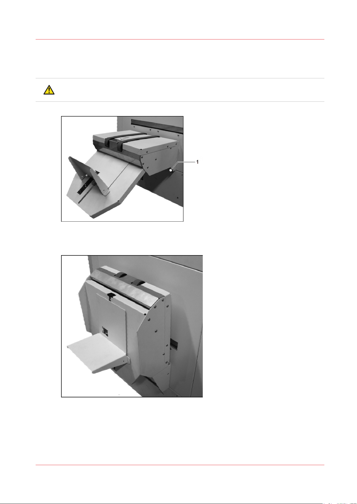
Raise and lower the side-trimmer stacker
Raise and lower the side-trimmer stacker
The stacker can be raised to allow access to other parts of the machine.
WARNING
Take care to keep your hands clear of the folding part of the stacker.
[9] The stacker
1. Turn release handle
[10] The stacker in raised position
Procedure - Raise the stacker
1. Press down on the top of the stacker, beside the green belts.
2. At the same time, push down on the stacker release handle.
3. Release pressure from the top of the stacker, the stacker will raise to a folded position.
Chapter 5 - Standard Tasks
31
Page 32

Raise and lower the side-trimmer stacker
Procedure - Lower the stacker
1. Push down on the top of the stacker until it clicks into position.
Chapter 5 - Standard Tasks
32
Page 33

Move the side-trimmer
The Book Stacker locks in position onto the Booklet Maker. The docking latch is released by a foot
pedal.
When to do
1. Access the mains ON/OFF switch.
2. Replace the mains input fuses.
Move the side-trimmer
[11] The Side-trimmer docking latch
Procedure
NOTE
If a book stacker is fitted, first move the book stacker, then start at step 3.
When needed, rotate the side-trimmer back to the docked position, the latch will click closed.
Action information
1 Remove the trim bin. See
2 Raise the side-trimmer stacker. See
3 Use your foot to release the docking latch. (see figure)
4 Rotate the Book Stacker away from the
Booklet Maker as far as the safety chain
allows.
How to use the
Raise and lower the side-trimmer stacker
on page 31.
The safety chain prevents damage to the power and communication cables.
on page 13.
Chapter 5 - Standard Tasks
33
Page 34

Remove and re-fit the book supports of the side-trimmer
Remove and re-fit the book supports of the sidetrimmer
There are five removable metal book supports in the side-trimmer. They must be removed when
small books are made and re-fitted for normal applications.
When to do
• Remove the book supports when the side-trim dimension is 190mm or less.
• Ensure the book supports are fitted when the side-trim dimension is over 190mm
[12] Top view of side-trimmer - centre book support
1. address book support
[13] Top view of side-trimmer - inner and outer book supports (centre book support removed)
1. Outer book support (left)
2. Inner book support (left)
3. Inner book support (right)
4. Outer book support (right)
Chapter 5 - Standard Tasks
34
Page 35

[14] Side-trimmer book supports
1.
Outer book support, left (marked LH OUT)
2.
Inner book support, left (marked LH IN)
3. address book support
4.
Inner book support, right (marked RH IN)
5.
Outer book support, right (marked RH OUT)
Remove and re-fit the book supports of the side-trimmer
[15] The side-trimmer
1. Top cover
2. Out feed Guard
Procedure - Removal
Step 1 - preparation
Rotate the side trimmer away from the booklet
maker.
Use the mains ON/OFF switch to turn OFF the
side trimmer.
Look through the top window of the side trimmer.
Note the position of the pivot bearings.
Move the side-trimmer
on page 33
Turn on the Two-side trimmer.
Chapter 5 - Standard Tasks
on page 15
4
35
Page 36

Remove and re-fit the book supports of the side-trimmer
If the pivot bearings are not visible:
There is enough space to remove the book
supports.
• Open the top cover of the side trimmer
• Go to "Step 2 - remove the center book support".
If the pivot bearings are visible:
• Use the mains ON/OFF switch to turn ON
the side trimmer.
• Look through the top window of the side
trimmer. The pivot bearings will move.
• If the pivot bearings are not visible, turn OFF
the side trimmer.
• Open the top cover of the side-trimmer.
• Go to "Step 2 - remove the center book support".
View through the top cover. Pivot bearings not
visible.
View through the top cover. Pivot bearings
visible.
Step 2 - remove the centre book support
The centre book support is secured with spring
clips.
Hold the centre book support with two hands
and pull in the direction shown by the arrow,
until it un-clips from the fixings.
Hold the out feed guard open with one hand
and remove the centre book support though
the opening.
See figure 'the side-trimmer'.
Step 3 - remove the inner book supports
Chapter 5 - Standard Tasks
36
4
Page 37

There are two inner book supports. Remove
one at a time.
Hold each end of the inner book support and
lift upwards.
Remove the inner book support through the
top of the machine.
Repeat with the other inner book support.
Step 4 - remove the outer book supports
There are two outer book supports. Remove
one at a time.
Hold each end of the outer book support and
lift upwards.
Remove and re-fit the book supports of the side-trimmer
1. Inner book support (right)
Remove the outer book support through the
top of the machine.
Repeat with the other outer book support.
Procedure - Refitting
Step 1 - preparation
Rotate the side trimmer away from the booklet
maker.
Use the mains ON/OFF switch to turn OFF the
side trimmer.
Look trough the top window of the side-trimmer.
Note the position of the pivot bearings.
1. address book support
Move the side-trimmer
on page 33
Turn on the Two-side trimmer.
on page 15
4
Chapter 5 - Standard Tasks
37
Page 38

Remove and re-fit the book supports of the side-trimmer
If the pivot bearings are not visible:
There is enough space to remove the book
supports.
• Open the top cover of the side trimmer
• Go to "Step 2 - fit the inner and outer book
supports".
If the pivot bearings are visible:
• Use the mains ON/OFF switch to turn ON
the side trimmer.
• Look through the top window of the side
trimmer. The pivot bearings will move.
• If the pivot bearings are not visible, turn OFF
the side trimmer.
• Open the top cover of the side-trimmer.
• Go to "Step 2 - fit the inner and outer book
supports".
View through the top cover. Pivot bearings not
visible.
View through the top cover. Pivot bearings
visible.
Step 2 - fit the inner and outer book supports
There are two outer book supports and two inner book supports.
Re-fit one at a time.
Refer to
of the side-trimmer
Remove and re-fit the book supports
on page 34.
On each book support, there are semicircular
cut outs at each end.
Position the cut-outs over the fixing points.
Press down on the book support so that it fits
onto the fixing points.
Repeat with the other book supports.
1. Fixing
2. Cut-out
Step 3 - fit the centre book support
Chapter 5 - Standard Tasks
38
4
Page 39

Hold the out feed guard open with one hand
and slide the centre book support in though
the opening.
Keep the book support central.
See figure 'The side-trimmer'.
The centre book support is secured with spring
clips.
Hold the centre book support with two hands.
Lift and slide forwards until it clips onto the fixings.
Remove and re-fit the book supports of the side-trimmer
Chapter 5 - Standard Tasks
39
Page 40

Remove and re-fit the book supports of the side-trimmer
Chapter 5 - Standard Tasks
40
Page 41

Chapter 6
Error Conditions, Problems and
Solutions
Page 42

Side-trimmer error
Introduction
This chapter describes how to correct problems that can occur with your Booklet maker. If a
problem persists, contact your service engineer.
Side-trimmer error
If a paper jam or other error occurs in the printer, the printer and the Booklet maker stop. The
type of error is displayed on the touch screen Error Messages. See
Refer also to your booklet maker user manual.
Error messages
on page 47.
Chapter 6 - Error Conditions, Problems and Solutions
42
Page 43

Quality problems
[16] Fore-edge trimming and side-trimming
1. Maximum fore-edge trim:
2. Side-Trim
3. Side-Trim
Trimming problems can affect the fore-edge trim or the side-trim. Make sure you follow the
correct fault-finding routine.
Quality problems
Side-trimming problems are explained in this manual. Fore-edge trimming problems are
explained in the booklet maker manual.
Trimming problem - the book is not trimmed
Adjust the User interface
Is the TRIM option turned off?
No Yes
|
V
Is the [AUTO]turned off in the [SIDE TRIM] window?
No Yes
¦ Set the [SIDE TRIM] setting to landscape.
¦ Does the problem persist?
¦
¦ ¦ No further action is required.
¦
V
Turn on the TRIM option.
Yes No
¦
V
If you need to use a custom trim size, enter the trim dimension in the TRIM
window. Make sure the size is at least 2mm less than the book size.
Open the top cover of the Two-side Trimmer. Wait for the side-trimmer to reset.
Does the problem persist?
Yes No
¦
V
No further action is required.
Chapter 6 - Error Conditions, Problems and Solutions
4
43
Page 44

Quality problems
Turn off the side-trimmer at the mains ON/OFF switch. Wait for 5 seconds and then turn on the
side-trimmer.
Does the problem persist?
Yes No
¦
V
Call your service engineer.
No further action is required.
Trimming problem - the book is not trimmed to the correct size
Is the [SIDE TRIM] setting turned on?
Yes No
¦
V
Is the correct trim size entered in the touchscreen? Make sure the size is at least 2mm less than
the book size.
Yes No
¦
V
Open the top cover of the Two-side Trimmer. Wait for the side-trimmer to reset. Does the problem persist?
Yes No
¦
V
Turn on the system
Enter the correct size in the touchscreen.
No further action is required.
Turn off the side-trimmer at the mains ON/OFF switch. Wait for 5 seconds and then turn on the
side-trimmer. Does the problem persist?
Yes No
¦
V
Call your service engineer.
No further action is required.
Side-trimming problem - the book is only trimmed on one side
This problem is normally caused by incorrect set-up. If the side-trim offset is slightly too large,
only one side is trimmed.
The [SIDE TRIM] is completely turned off.
No Yes
¦ Set the [SIDE TRIM] setting to landscape.
¦ Does the problem persist?
¦
¦ ¦ No further action is required.
Yes No
4
Chapter 6 - Error Conditions, Problems and Solutions
44
Page 45

Quality problems
¦
V
¦
¦
If you need to use a custom trim size, enter the trim dimension in the TRIM
window. Make sure the size is at least 2mm less than the book size.
Open the top cover of the Two-side Trimmer. Wait for the side-trimmer to reset. Does the problem persist?
Yes No
¦
No further action is required.
V
Turn off the side-trimmer at the mains ON/OFF switch. Wait for 5 seconds and then turn on the
side-trimmer. Does the problem persist?
Yes No
¦
No further action is required.
V
Call your service engineer.
Trimming problem - the book is not trimmed square
Open the top cover of the Two-side Trimmer. Wait for the side-trimmer to reset. Does the problem persist?
Yes No
¦
No further action is required.
V
Open the top cover of the Two-side Trimmer. There will be paper trimmings on the large black
waste conveyor belt - this is normal. Are there paper trimmings or a book in other places?
No Yes
¦ Clear the paper trimmings or book.
¦ Does the problem persist?
¦
¦
V
Yes No
¦
No further action is needed.
V
Is the side-trim dimension more than 190mm?
No Yes
¦ Are the book supports fitted?
¦
¦ ¦ Fit the book supports, see
Yes No
trimmer
Remove and re-fit the book supports of the side-
on page 34.
¦ ¦ Does the problem persist?
¦ ¦
¦
V
¦
V
Yes No
¦
No further action is needed.
V
Turn off the Side-Trimmer at the mains ON/OFF switch. Wait for 5 seconds and then turn on the
Side-Trimmer. Does the problem persist?
Chapter 6 - Error Conditions, Problems and Solutions
4
45
Page 46

Quality problems
Yes No
¦
No further action is required.
V
Call your service engineer.
Trimming problem - poor trim quality
The book is trimmed to the correct size and offset, but the trim quality is bad.
NOTE
Certain book thicknesses or material can result in a small witness mark on the bottom corner of
the spine, this is normal.
[17] Normal side-trim blade witness mark
If the side-trim dimension is over 190mm, check that the book supports are fitted. See
and re-fit the book supports of the side-trimmer
Call your service engineer if there are marks on the trimmed edge different to a normal witness
mark or if the edge is badly trimmed.
Side-trimming problem - cannot enter settings
If the user interface will not accept the required settings, this can be due to the following
conditions:
• The [SIDE TRIM]window needs to refresh. Touch [CLOSE] and then re-open the [SIDE TRIM]
window.
• The side-trim setting will conflict with the stitch position. Reduce the [STITCH PITCH] to move
the stitch position away from the trim edge.
• The trim position is set larger than the book.
• The side-trim offset is too big relative to the book size and/or the amount of trim.
Remove
on page 34.
Chapter 6 - Error Conditions, Problems and Solutions
46
Page 47

Error messages
Information and error messages are shown in the message list.
Refer also to your booklet maker user manual.
The error messages are shown in order of priority. Follow the action needed for the messages,
starting with the message at the top of the list.
To display the information about a message:
• Touch HELP then touch the message list.[HELP]
• Use the right-arrow and left-arrow to see the help text for each message.
Message Information
Error messages
[CHECK THE SIDE TRIM
BIN]
[JAM AT SIDE TRIM INFEED]
[JAM AT SIDE TRIM OUTFEED]
[JAM IN SIDE TRIM]
The trim bin is either open or full. Check the trim bin.
Empty the trim bin if necessary.
See
Empty the trim bin
Open the top cover of the Two-side Trimmer.
Then, if necessary, open the top cover of the side-trimmer and
check for paper trimmings or obstructions. Close the top cover of
the Two-side Trimmer.
If the message is not cleared, use the stacker mains ON/OFF
switch. Turn the side-trimmer off, wait at least 5 seconds and then
turn the side-trimmer on.
If the problem continues, then call your service engineer.
on page 28.
[Side trim axis moving] The trim axis (size adjustment) is moving. This message clears
when the adjustment is complete. If the message does not clear:
Open the top cover of the Two-side Trimmer.
Then, if necessary, open the top cover of the side-trimmer and
check for paper trimmings or obstructions. Close the top cover of
the Two-side Trimmer.
If the message is not cleared, use the stacker mains ON/OFF
switch. Turn the side-trimmer off, wait at least 5 seconds and then
turn the side-trimmer on.
If the problem continues, then call your service engineer.
Chapter 6 - Error Conditions, Problems and Solutions
4
47
Page 48

Error messages
Message Information
[SIDE TRIM COVER OPEN] Open the top cover of the Two-side trimmer.
[SIDE TRIM] - [No comms] Check that the mains power input cable and the communications
Close the top cover of the Two-side Trimmer.
If the message does not clear, open and then close the top cover
of the side-trimmer.
If the message is not cleared, use the stacker mains ON/OFF
switch. Turn the side-trimmer off, wait at least 5 seconds and then
turn the side-trimmer on.
If the problem continues, then call your service engineer.
cable are connected.
See
Description of the side-trimmer
on page 11.
Use the mains ON/OFF switch. Turn the side-trimmer off, wait at
least 5 seconds and then turn the side-trimmer on.
If the problem continues, then call your service engineer.
[SYSTEM ERROR #]
41.39
[SYSTEM ERROR #]
41.xx
If the side-trimmer setting is 190mm or less, check that the book
supports are removed. Otherwise, follow the instructions below
for other 41.xx system errors.
See
Remove and re-fit the book supports of the side-trimmer
on
page 34.
Open the top cover of the side-trimmer and check for paper trimmings or obstructions. Close the top cover of the Two-side Trimmer.
If the message is not cleared, use the stacker mains ON/OFF
switch. Turn the side-trimmer off, wait at least 5 seconds and then
turn the side-trimmer on.
If the problem continues, then call your service engineer.
Chapter 6 - Error Conditions, Problems and Solutions
48
Page 49

Paper jams
1. Open and then close the top cover of the side-trimmer.
2. Then, if necessary, open the top cover of the side-trimmer and check for paper trimmings or
obstructions. Close the top cover of the side-trimmer.
3. If the message still does not clear, use the side-trimmer mains ON/OFF switch. Turn the sidetrimmer off, wait at least 5 seconds and then turn the side-trimmer on.
4. If paper jams in the booklet-making system continue, then clean the book supports and the
outfeed lower guide. See
If the problem continues, then call your service engineer.
Operator maintenance
Paper jams
on page 53.
Chapter 6 - Error Conditions, Problems and Solutions
49
Page 50

Change the fuses - side-trimmer
Change the fuses - side-trimmer
Introduction
The Booklet maker has two fuses at the power input. See
page 11.
If either fuse has blown, the Book Stacker will not operate.
WARNING
Turn OFF the machine and remove the mains power supply cable before you change the fuses.
This machine uses two fuses in parallel.
WARNING
To avoid the risk of fire, replace fuses using only the same type and rating.
Fuse Description
• - 7A, HRC Quick acting, F
Procedure
1. Turn off the Two-side trimmer.
2. Disconnect the Book Stacker from the power supply.
3. Check each fuse.
4. If the fuse is blown, then replace with a fuse of the correct specification.
Description of the side-trimmer
on
Result
If the fuse blows again, call your service engineer.
Chapter 6 - Error Conditions, Problems and Solutions
50
Page 51

Chapter 7
Maintenance
Page 52

Service and maintenance
Service and maintenance
Service maintenance is scheduled according to the booklet maker use. After every one-million
stitches (every 3rd spool of stitch-wire), the side-trimmer needs service.
Only an approved service engineer can service the side-trimmer. Contact your supplier for further
information.
Chapter 7 - Maintenance
52
Page 53

Operator maintenance
1
2
We recommend that you clean the side-trimmer every week to remove surface dust.
CAUTION
Only clean the machine with materials that are recommended in this manual. Do not use other
chemicals or abrasive material.
Use a moist cloth to clean the outside of the side-trimmer.
Clean the outfeed lower guide
When to do
• When there are repeated book jams in the booklet-making system.
Materials needed
• Cleaning cloth
• Household spray polish that contains silicone
Operator maintenance
NOTE
Do not polish onto any of the belts.
• For ink-based printers only: cleaning fluid that is supplied to clean the printer
[18] Side-trimmer
1. Top cover.
2. Outfeed guard.
[19] Outfeed lower guide
Chapter 7 - Maintenance
53
Page 54

Operator maintenance
1. Outfeed guard, lifted.
2. Outfeed lower guide.
Procedure
1. Use the mains ON/OFF switch to turn OFF the side trimmer.
2. Use your hand to lift the outfeed guard. See figure 18.
3. For ink-based printers only:
Apply a small quantity of polish onto a cloth and clean the outfeed lower guide. See figure 19.
4. For ink-based and toner-based printers:
Apply a small quantity of polish onto a cloth and clean the outfeed lower guide. See figure 19.
NOTE
Do not polish onto any of the belts.
5. Lower the outfeed guard.
6. Use the mains ON/OFF switch to turn ON the side trimmer.
Clean the book supports
When to do
• When there are repeated book jams in the booklet-making system.
Materials needed
• Cleaning cloth
• Household spray polish that contains silicone
• For ink-based printers only: cleaning fluid that is supplied to clean the printer
Procedure
1. Remove the book supports. See
page 34.
2. For ink-based printers only:
Apply the prescribed cleaning liquid onto a cloth and clean the book supports.
3. For ink-based and toner-based printers:
Apply a small quantity of polish onto a cloth and clean the book supports.
4. Fit the book supports. See
page 34.
Remove and re-fit the book supports of the side-trimmer
NOTE
Do not polish onto any of the belts.
Remove and re-fit the book supports of the side-trimmer
on
on
Chapter 7 - Maintenance
54
Page 55

Chapter 8
Specifications
Page 56

Operating conditions
10-35°C
35-85% relative humidity
Up to 2,000 m above mean sea level
Production
Book size
Book Thickness
Trimming
Stacker capacity
Minimum set time: 3.8 seconds
950 books trimmed per hour
Minimum trimmed book size: 120 x 80mm
Maximum input size: 380 x 310mm
Maximum finished book thickness: 10.4mm (approx 208 pages
80g/m²)
Minimum book height one sheet folded to make a 4- page booklet
Minimum line width 120mm
Maximum print width 380mm (no trim); 378mm (trimmed)
Side Trim: 40mm each side
Side Trim: 1mm each side
Output conveyor: 20 books*
Book Stacker (optional): 930mm
Dimensions & weight
Power supply
Power consumption
Noise Emission
Approvals
Radio frequency emissions
Width: 1142mm (installed)
Depth: 924mm
Height: 885 - 968mm (adjustable)
Weight: 300kg
Side-Trimmer: 220-240V AC, 50/60Hz, 4A
stand-by: 40VA (10W)
in operation: 1200VA (750W) during trimming (1 second of cycle)
stand-by: ambient
in operation: 66 dB (A), peak 87 dB (A)
Complies with CE and UL. Conforms to FCC rules Part 15 Class A
and VCCI Class A.
This equipment has been tested and found to comply with the limits for a Class A digital device, pursuant to Part 15 of the FCC
Rules. These limits are designed to provide reasonable protection
against harmful interference when the equipment is operated in a
commercial environment.
This equipment generates, uses, and can radiate radio frequency
energy and, if not installed and used in accordance with the instruction manual, may cause harmful interference to radio communications. Operation of this equipment in a residential area is
likely to cause harmful interference in which case the user will be
required to correct the interference at his own expense.
4
Chapter 8 - Specifications
56
Page 57

* Standard book is made from 20 sheets of 80 g/m² paper, with 2 stitches.
Production may vary according to operating conditions. In line with a policy of continual product improvement, the manufacturer reserves the right to alter the materials or specification of
this product at any time without notice.
Chapter 8 - Specifications
57
Page 58

Chapter 8 - Specifications
58
Page 59

Chapter 9
Declaration of Conformity
Page 60

According to ISO/IEC 17050-1
This declaration of conformity is issued under the sole responsibility of the manufacturer.
Name of Manufacturer:
Address of Manufacturer:
Watkiss Automation Limited
Watkiss House
Blaydon Road
Sandy
SG19 1RZ
United Kingdom
Object of the declaration:
Watkiss P2T 2-Knife Trimmer
Serial Number WA/P2T/0001 onwards
The object of the declaration described above is in conformity with the relevant Union harmonization legislation:
2014/35/EU - Low Voltage Directive
2014/30/EU -EMC Directive
References to the relevant harmonized standards used or references to the specifications in relation to which conformity is declared:
- Safety: EN 60950-1:2006 / A11:2009 / A1:2010 /
A12:2011 / A2:2013
- EMC: EN55022:2010 Class A
EN55024:2010
EN61000-3-2:2014
EN61000-3-3:2013
- RoHS: 2011/65/EC Council Directive EN50581:2012
- WEEE: 2002/96/EC Council Directive amended by
2008/34/EC and 2008/35/EC
- Reach: REGULATION (EC) No. 1907/2006
M C Watkiss
Technical Director, Watkiss Automation Ltd.
September 30, 2016
Chapter 9 - Declaration of Conformity
60
Page 61

Page 62

Canon Inc.
www.canon.com
Canon U.S.A., Inc.
www.usa.canon.com
Canon Canada Inc.
www.canon.ca
Canon Europe Ltd
www.canon-europe.com
Canon Latin America Inc.
www.cla.canon.com
Canon Australia PTY. Ltd
www.canon.com.au
Canon China Co., Ltd
www.canon.com.cn
Canon Singapore PTE. Ltd
www.canon.com.sg
Canon Hongkong Co., Ltd
www.canon.com.hk
© Océ 2018
 Loading...