

Page 1
For Océ and Imagistics Models
Océ Facsimile Operations Manual
im4512/im3512/im4511 / im3511
Page 2
TO USERS OF THE im4512/im3512
Thank you for purchasing an ZB3500590 Facsimile Expansion Kit. The Facsimile Operation Manual that is included
in the kit explains the procedures for using the fax function on im4511/im3511, and thus some sections do not apply
to the im4512/im3512. This guide explains those sections, and should be used together with the Facsimile
Operation Manual.
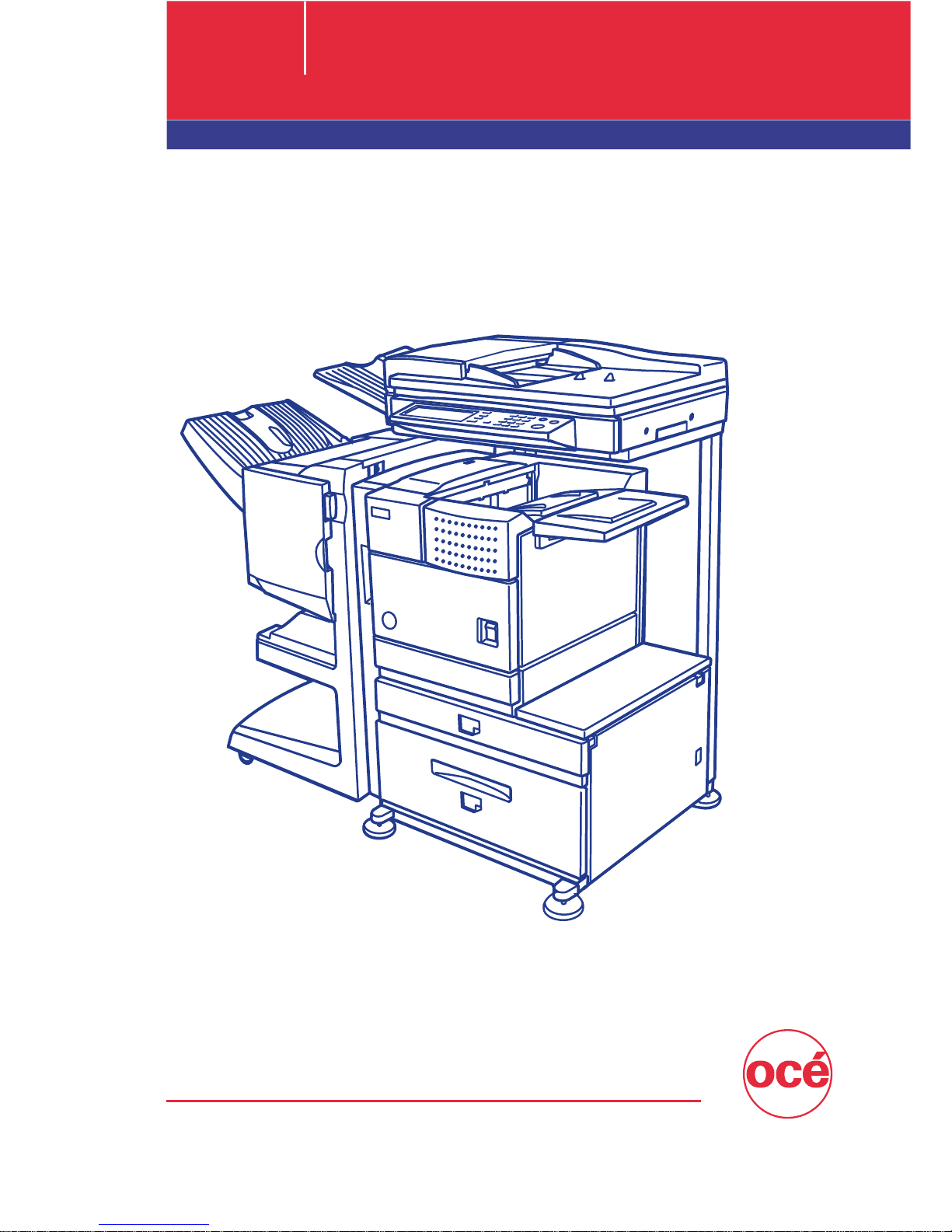
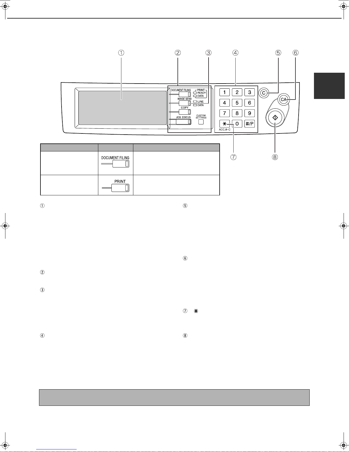
1. OPERATION PANEL
The operation panel of the im4512/im3512 is different from the panel described in the Facsimile Operation Manual.
When reading explanations that use an illustration of the operation panel, refer to the illustration below. For the
names and functions of the keys, see "A LOOK AT THE OPERATION PANEL" in the Facsimile Operation Manual
(page 1-3). (The numbers in the illustration correspond to the explanations.)
PRINT
DOCUMENT
FILING
IMAGE SEND
COPY
JOB STATUS
READY
DATA
LINE
DATA
SYSTEM
SETTINGS
LOGOUT
Model Key name
The im4512/im3512 with the document filing
function added
The im4512/im3512 without the document filing
function
DOCUMENT
FILING
PRINT
1
Page 3
[SYSTEM SETTINGS] Key
SYSTEM
SETTINGS
SYSTEM
SETTINGS
SYSTEM
SETTINGS
ADMINISTRATOR SETTINGS
SENDER CONTROL
FAX DATA
RECEIVE/FORWARD
ADMINISTRATOR PASSWORD
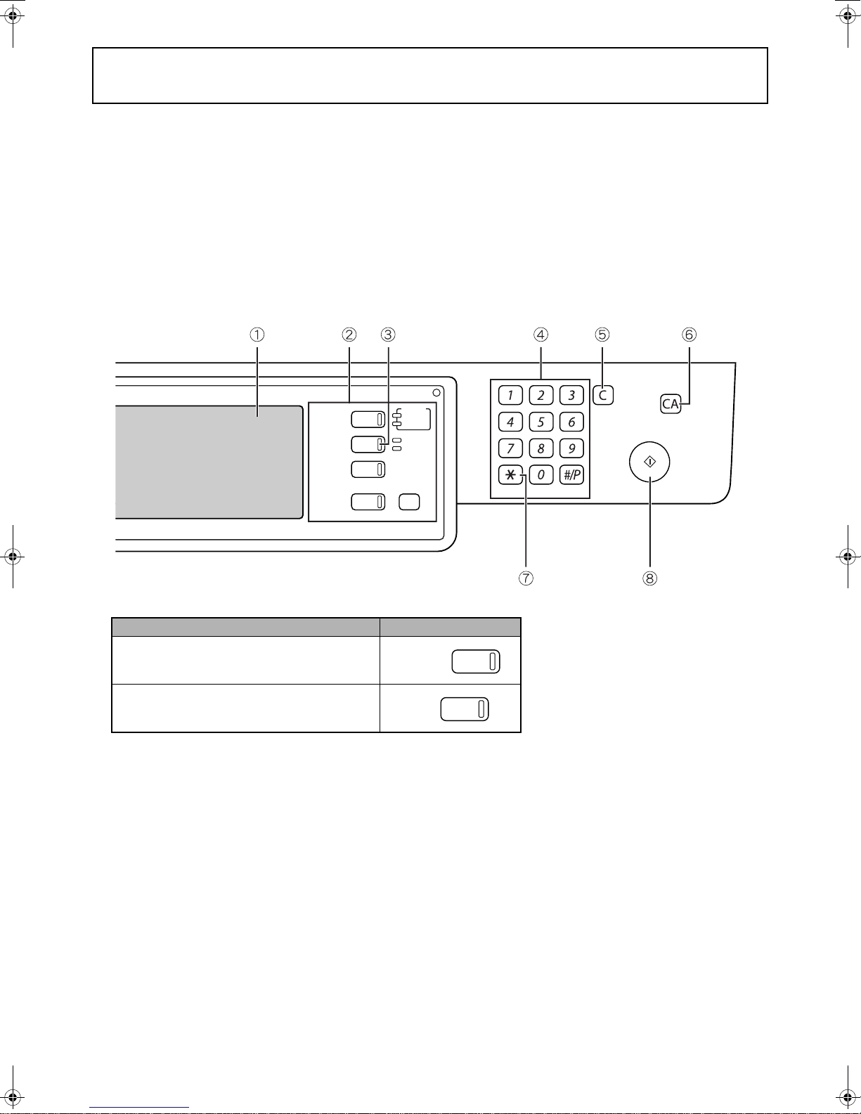
The [SYSTEM SETTINGS] key on the operation panel is called the [CUSTOM SETTINGS] key in the Facsimile
Operation Manual. When configuring system settings, refer to the illustration below. At other places in the Operation
manual that refer to the "Custom Settings", substitute "System Settings".
Location in
Facsimile Operation Manual
* With respect to the administrator settings, see the following.
When using the
im4512/im3512
Applicable function
USING THE TRANSFER
FUNCTION
Changes in the fax reception
function
STORING, EDITING, AND
DELETING AUTO DIAL
KEYS AND PROGRAMS
STORING A GROUP INDEX
PROGRAMMING,
EDITING, AND DELETING
FCODE MEMORY BOXES
EDITING AND DELETING
A MEMORY BOX
PRINTING PROGRAMMED
INFORMATION
ADMINISTRATOR
SETTINGS*
Operation manual page
(chapter)
Page 3-18
Page 5-2
Page 6-2
Page 6-9
Page 6-10
Page 6-14
Page 6-14
Chapter 8
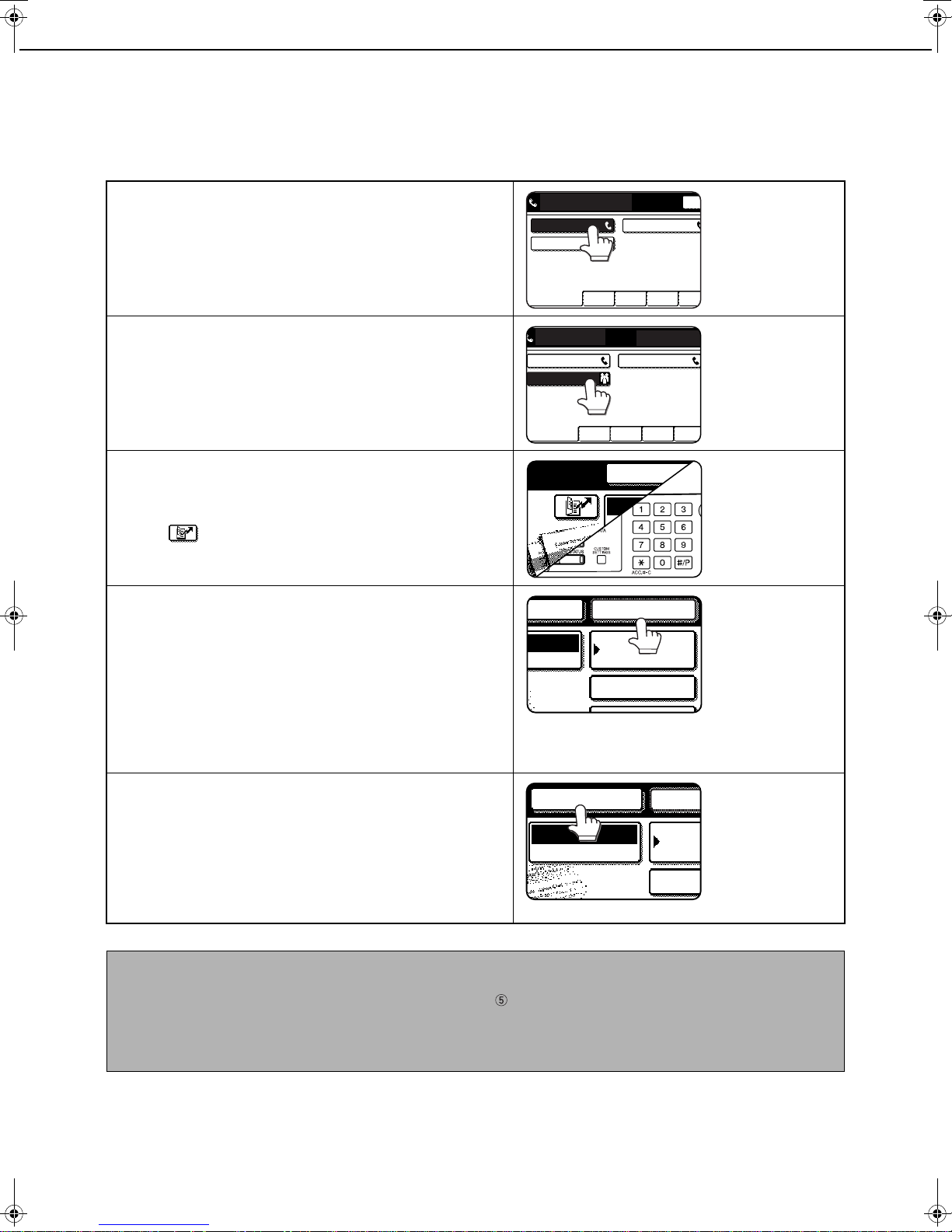
2. ADMINISTRATOR SETTINGS
The "Administrator Settings" in the system settings are referred to as "Key Operator Programs" in the Facsimile
Operation Manual. For explanations of the administrator settings for the fax function, see chapter 8, "KEY
OPERATOR PROGRAMS", in the Facsimile Operation Manual.
At places in the Facsimile Operation Manual that refer to the "Key Operator Programs", substitute "Administrator
Settings".
Due to this change, steps 1 to 3 on pages 8-3 and 8-11 are as follows.
Press the [SYSTEM SETTINGS] key.
1
Touch the [ADMINISTRATOR SETTINGS]
2
key.
Enter the administrator password (5-digit
3
number) with the numeric keys.
The factory default
administrator password
is indicated on page 2 of
Administrator settings
guide.
For the steps that follow, see pages 8-3 and 8-11 of the
Facsimile Operation Manual.
2
Page 4

3. INBOUND ROUTING SETTINGS
Received faxes can be automatically forwarded to an e-mail address. This function can be used to forward received
faxes directly to an e-mail address without printing the faxes.
The machine
Received fax
Forwarding
NOTES
● To use the inbound routing function for received faxes, the network scanner expansion kit must be installed.*
*1 The im4512/im3512 require the network expansion kit (ZB3500980).
● The file format of forwarded faxes is TIFF.
Configuring Inbound Routing Settings
Inbound routing settings are configured in the Web pages. For the procedure for accessing the Web pages, see
"ACCESSING WEB PAGES" in the Operation Manual For Image Send Functions. After configuring the settings, be
sure to click [Submit] to save them.
1
■ Enabling inbound routing
Enable this function before configuring the inbound
routing settings.
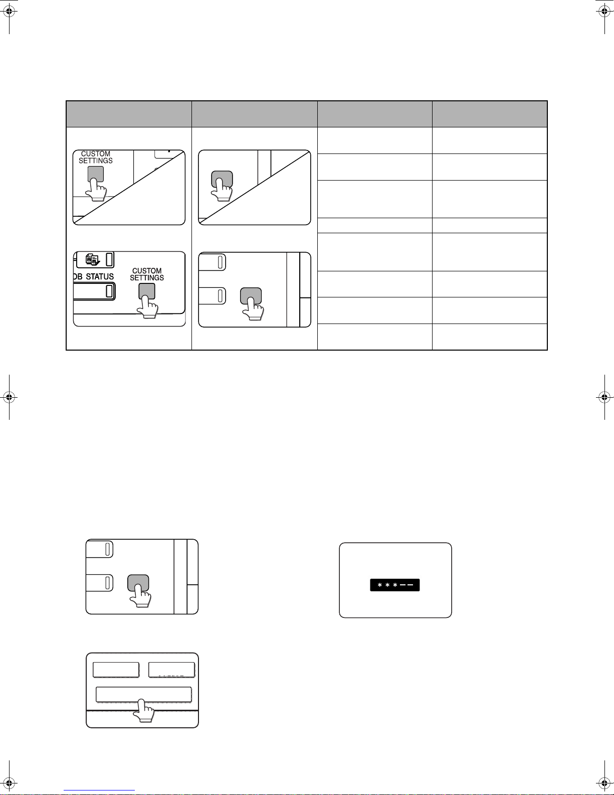
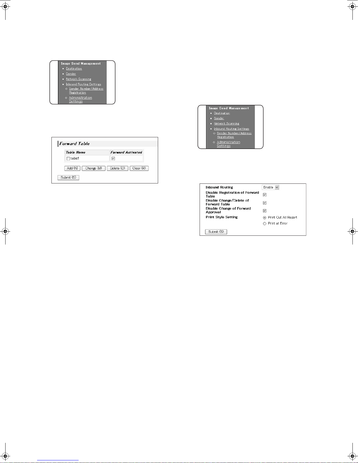
Click "Administration Settings" in
1
"Inbound Routing Settings" in the menu
frame.
Administrator rights are required to access the
"Administration Settings".
Enable "Inbound Routing".
2
■ Store sender numbers
Create a list of sender fax numbers. The list created
here will be selected in "Sender Number/Address
Registration" when a forwarding table is stored in
step 9. Up to 500 sender fax numbers can be stored.
Click "Sender Number/Address
4
Registration" in "Inbound Routing
Settings" in the menu frame.
The "Sender Number/Address Registration"
screen will appear.
Enter a fax number and click [Add to List].
5
This enables the inbound routing settings.
Click [Submit].
3
3
To delete an entered fax number, select the fax
number that you wish to delete from "Address to be
Entered" and click [Delete].
Click [Submit].
6
Page 5
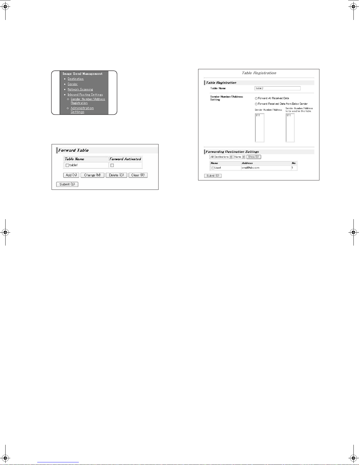
■ Storing a forwarding table
Specify a sender and a forwarding destination to create a table (list) that combines the sender and the
forwarding address to which faxes from that sender are sent. The table will be added to the list of tables in the
"Inbound Routing Settings" screen. Up to 50 tables can be stored.
Click "Inbound Routing Settings" in the
7
menu frame.
The "Inbound Routing Settings" screen appears.
Click [Add].
8
The "Table Registration" screen appears.
Enter a table.
9
● Table Registration
Tabl e N a m e :
The name that appears as the "Table Name" in
the "Inbound Routing Settings" screen.
Sender Number/Address Setting:
If you wish to have received faxes from all
senders forwarded, select "Forward All Received
Data". If you wish to forward the faxes of specified
senders, select "Forward Received Data from
Below Sender" and select the sender whose
faxes you wish to forward from the addresses
shown in "Sender Number/Address". Multiple
addresses can be selected using the Shift key or
the Ctrl key. Only an address that was stored in
steps 4 to 6 can be selected here.
● Forwarding Destination Settings
Forwarding Destination Setting:
Specify the destination to which received faxes
will be forwarded. Select the forwarding address
from one-touch keys or group keys stored in the
machine. Up to 1000 forwarding destinations can
be stored.
4
Click [Submit].
10
Page 6
■ Activate the table
Activate the stored table to use it for forwarding.
Click "Inbound Routing Settings" in the
11
menu frame.
The "Inbound Routing Settings" screen appears.
Select the [Forward Activated] checkbox of
12
the table that you wish to activate.
To delete a table, select the checkbox of the table
and click [Delete].
■ Configuring advanced inbound
routing settings
Advanced inbound routing settings can be
configured for such purposes as prohibiting the
storing of tables and prohibiting changes to the
table activation settings. Administrator rights are
required for these settings.
Click "Administration Settings" in
14
"Inbound Routing Settings" in the menu
frame.
Administrator rights are required to access the
"Administration Settings".
Configuring administrator settings.
15
Click [Submit].
13
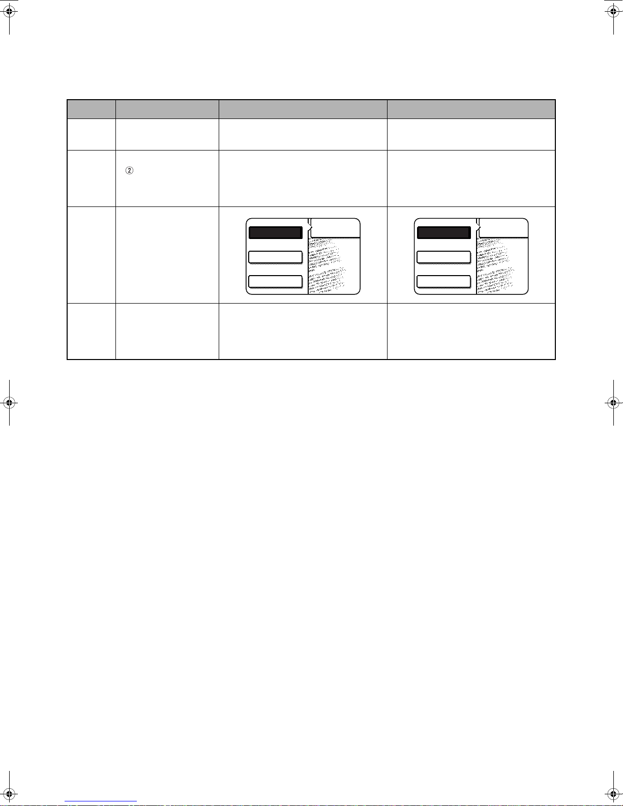
● Administration Settings
Inbound Routing:
Enable or disable inbound routing.
Disable Registration of Forward Table:
To prohibit the storing of tables, select this
checkbox.
Disable Change/Delete of Forward Table:
To prohibit the changing and deleting of tables,
select this checkbox.
Disable Change of Forward Approval:
To prohibit changes to the activation settings of
tables, select this checkbox.
Print Style Setting:
Set the condition for printing received faxes.
To print out all received faxes when they are
forwarded, select [Print Out All Report]. To print
out received faxes only when a forwarding error
occurs, select [Print at Error].
5
Click [Submit].
16
Page 7
4. OTHER CHANGES
FAX
E-MAIL/FTP
MODE SWITCH
INTERNET FAX
FAX
SCAN
MODE SWITCH
INTERNET FAX
When using the fax function on the im4512/im3512, make the following substitutions in the Facsimile Operation
Manual.
Page Changes Location in Facsimile Operation Manual When using the im4512/im3512
0-1
1-4
2-2, 2-6
2-7
8-4
"INTRODUCTION"
" " in the "Condition
settings screen"
Step 1
"Default display settings"
Network Scanning Operation Manual Operation Manual For Image Send
Functions
Use this key when the network scanner
option is installed to switch between the
"E-MAIL/FTP" and "INTERNET FAX"
screens
● [E-MAIL/FTP] (when the network
scanner option is installed)
● [INTERNET-FAX] (when the network
scanner option is installed)
Use this key when the network scanner
option is installed to switch between the
"SCAN" and "INTERNET FAX" screens
● [SCAN] (when the network scanner
option is installed)
● [INTERNET-FAX] (when the Internet
fax option is installed)
6
Page 8

Page 9

This manual has been printed using a vegetable-based soy oil ink
to help protect the environment.
Printed on 100% post-consumer recycled paper
PRINTED IN CHINA
2007J KS1
TINSE3942FCZZ
Page 10

■■■■ CAUTION:
To reduce the risk of fire, use only UL-Listed No.26 AWG or larger telecommunication line cord.
■■■■ WARNING:
FCC Regulations state that any unauthorized changes or modifications to this equipment not expressly
approved by the manufacturer could void the user's authority to operate this equipment.
■■■■ FAX interface cable and Line cable:
These special accessories must be used with the device.
■■■■ NOTE:
This equipment has been tested and found to comply with the limits for a Class A digital device, pursuant to
part 15 of the FCC Rules.
These limits are designed to provide reasonable protection against harmful interference when the equipment is
operated in a commercial environment.
This equipment generates, uses, and can radiate radio frequency energy and, if not installed and used in
accordance with the instruction manual, may cause harmful interference to radio communications.
Operation of this equipment in a residential area is likely to cause harmful interference in which case the user
will be required to correct the interference at his own expense.
Page 11

INTRODUCTION
Thank you for purchasing this product. This manual only explains the facsimile functions of the product. For safety
precautions and general information on using the machine such as loading paper, clearing misfeeds, and handling
peripheral units, see the "Copying operation manual". For other functions, see the following manuals as appropriate:
Copier function
General and copier-related key operator programs
Printer function
Network scanner function
The explanations in this manual assume that certain peripheral units are installed.
: See "Copying operation manual".
: See the key operator's guide.
: See "Printing operation manual". (if the printer option is installed)
: See "Network scanning operation manual". (if the network scanner option is installed)
0-1
Page 12

CONTENTS
Page
INTRODUCTION ........................................................ 0-1
TO USE THIS PRODUCT CORRECTLY AS A
FACSIMILE................................................................. 0-4
● FCC NOTICE TO USERS ....................................... 0-5
● ABOUT THE TELEPHONE CONSUMER
PROTECTION ACT OF 1991.................................. 0-6
● IMPORTANT SAFETY INFORMATION .................. 0-6
● NOTICE FOR USERS IN CANADA ........................ 0-7
● AVIS POUR NOS UTILISATEURS AU CANADA ... 0-7
CHAPTER 1
BEFORE USING THE FAX FEATURE
POINTS TO CHECK AND PROGRAM AFTER
INSTALLATION .......................................................... 1-2
CONNECTING AN EXTENSION PHONE .................. 1-2
● CONNECTING AN EXTENSION PHONE ............... 1-2
A LOOK AT THE OPERATION PANEL...................... 1-3
● FAX MODE (CONDITION SETTINGS SCREEN) ... 1-4
ORIGINALS ................................................................ 1-6
● ORIGINALS THAT CAN BE FAXED ....................... 1-6
LOADING A DOCUMENT........................................... 1-7
●
USING THE AUTOMATIC DOCUMENT FEEDER...........
● USING THE DOCUMENT GLASS .......................... 1-7
CHECKING THE SIZE OF A LOADED ORIGINAL .... 1-8
● MANUALLY SETTING THE SCANNING SIZE ....... 1-8
STORING, DELETING, AND USING ORIGINAL SIZES ......
● STORING OR DELETING AN ORIGINAL SIZE...... 1-9
● USING A STORED ORIGINAL SIZE....................... 1-9
SELECTING RESOLUTION AND EXPOSURE SETTINGS ....
● SELECTING THE RESOLUTION............................ 1-10
● SELECTING THE EXPOSURE ............................... 1-11
CONVENIENT DIALING METHODS.......................... 1-12
1-7
1-9
1-10
CHAPTER 3
USING CONVENIENT FUNCTIONS 1
ADVANCED TRANSMISSION METHODS
SENDING THE SAME DOCUMENT TO MULTIPLE
DESTINATIONS IN A SINGLE OPERATION
(BROADCAST TRANSMISSION) ............................... 3-2
● USING BROADCAST TRANSMISSION.................. 3-3
ERASING EDGE SHADOWS (EDGE ERASE)........... 3-4
● USING EDGE ERASE ............................................. 3-4
FAXING A DIVIDED ORIGINAL (DUAL PAGE SCAN) ...
AUTOMATIC TRANSMISSION AT A SPECIFIED
TIME (TIMER TRANSMISSION)................................. 3-6
● SETTING UP A TIMER TRANSMISSION ............... 3-6
TRANSMITTING TWO ORIGINAL PAGES AS A
SINGLE PAGE (2in1).................................................. 3-7
● USING 2in1.............................................................. 3-7
FAXING THE FRONT AND BACK SIDES OF A
CARD ON ONE SHEET OF PAPER (CARD SHOT) .. 3-8
● USING CARD SHOT ............................................... 3-8
FAXING A LARGE NUMBER OF PAGES (JOB BUILD MODE)
OWN NUMBER SENDING.......................................... 3-11
PRINTING OUT THE RESULT OF A TRANSMISSION
(TRANSACTION REPORT)......................................... 3-12
TRANSMISSION AND RECEPTION USING THE
POLLING FUNCTION ................................................. 3-13
● USING THE POLLING FUNCTION ......................... 3-14
● USING POLLING MEMORY.................................... 3-15
PROGRAMMING FREQUENTLY USED OPERATIONS ..........
● USING A PROGRAM............................................... 3-17
TRANSFERRING RECEIVED FAXES TO ANOTHER MACHINE WHEN
PRINTING IS NOT POSSIBLE (FORWARDING FUNCTION)
● USING THE TRANSFER FUNCTION ..................... 3-18
FAXING DIRECTLY FROM A COMPUTER (PC-FAX FUNCTION)
.............. 3-18
3-5
3-10
3-17
.... 3-19
CHAPTER 2
BASIC OPERATIONS
SENDING A FAX ........................................................ 2-2
● BASIC PROCEDURE FOR SENDING FAXES ....... 2-2
● TRANSMISSION BY AUTO-DIALING (ONE-
TOUCH DIALING AND GROUP DIALING) ............. 2-4
● SENDING A FAX BY SPEED DIALING .................. 2-4
● FAX NUMBER ENTRY WITH GLOBAL ADDRESS
SEARCH.................................................................. 2-5
● ENLARGING/REDUCING THE IMAGE BEFORE
TRANSMISSION ..................................................... 2-6
● FAXING A TWO-SIDED ORIGINAL ........................ 2-7
PRIORITY TRANSMISSION OF A STORED JOB ..... 2-9
CANCELING A FAX TRANSMISSION ....................... 2-9
● CANCELING ON-HOOK DIALING .......................... 2-9
RECEIVING FAXES ................................................... 2-10
● RECEIVING A FAX ................................................. 2-10
CHAPTER 4
USING CONVENIENT FUNCTIONS 2
TRANSMISSION USING F-CODES
TRANSMISSION BETWEEN MACHINES SUPPORTING F-CODES
●
MEMORY BOXES AND SUB-ADDRESSES/PASSCODES
REQUIRED FOR F-CODE TRANSMISSION
● ENTERING (DIALING) A FAX NUMBER WITH A
SUB-ADDRESS AND PASSCODE ......................... 4-3
●
CREATING A MEMORY BOX FOR F-CODE TRANSMISSION
F-CODE POLLING MEMORY..................................... 4-4
● USING F-CODE POLLING MEMORY..................... 4-4
● PROCEDURE FOR F-CODE POLLING.................. 4-5
F-CODE CONFIDENTIAL TRANSMISSION............... 4-6
● F-CODE CONFIDENTIAL TRANSMISSION ........... 4-6
●
PRINTING A DOCUMENT RECEIVED TO AN F-CODE
CONFIDENTIAL MEMORY BOX
F-CODE RELAY BROADCAST TRANSMISSION...... 4-8
● USING THE F-CODE RELAY BROADCAST
FUNCTION (your machine is the relay machine) .... 4-9
●
USING THE F-CODE RELAY REQUEST FUNCTION
(your machine requests a relay broadcast).................
................................ 4-7
................... 4-2
... 4-2
... 4-3
4-9
0-2
Page 13

CONTENTS
CHAPTER 5
USING CONVENIENT FUNCTIONS 3
CONVENIENT METHODS OF USE
Page
USING AN EXTENSION PHONE............................... 5-2
●
USING AN EXTENSION PHONE TO RECEIVE A FAX...
● RECEIVING A FAX AFTER TALKING (MANUAL
RECEPTION) .......................................................... 5-3
●
SENDING A FAX AFTER TALKING (MANUAL
TRANSMISSION).........................................................
5-2
5-4
CHAPTER 6
PROGRAMMING
PROGRAMMING ........................................................ 6-2
STORING, EDITING, AND DELETING AUTO DIAL
KEYS AND PROGRAMS............................................ 6-2
● STORING ONE-TOUCH DIAL KEYS ...................... 6-3
● EDITING AND DELETING ONE-TOUCH KEYS ..... 6-5
● STORING A GROUP KEY ...................................... 6-6
● EDITING AND DELETING GROUP KEYS.............. 6-7
● STORING A PROGRAM ......................................... 6-8
● EDITING AND DELETING PROGRAMS ................ 6-8
STORING A GROUP INDEX...................................... 6-9
PROGRAMMING, EDITING, AND DELETING F-CODE
MEMORY BOXES
● PROGRAMMING AN F-CODE MEMORY BOX ...... 6-10
● SETTING FOR F-CODE POLLING MEMORY
BOXES (POLLING TIMES) ..................................... 6-11
●
SETTING FOR F-CODE CONFIDENTIAL
TRANSMISSION MEMORY BOXES (PRINT PIN) ......
● SETTING FOR F-CODE RELAY BROADCAST
MEMORY BOXES (RECIPIENT) ............................ 6-13
● EDITING AND DELETING A MEMORY BOX ......... 6-14
PRINTING PROGRAMMED INFORMATION............. 6-14
........................................................ 6-10
6-12
CHAPTER 8
KEY OPERATOR PROGRAMS
Page
KEY OPERATOR PROGRAMS.................................. 8-2
● KEY OPERATOR PROGRAM LIST ........................ 8-2
● USING THE KEY OPERATOR PROGRAMS.......... 8-3
● KEY OPERATOR PROGRAMS............................... 8-4
● OPERATION SETTINGS......................................... 8-4
● FAX SETTINGS ....................................................... 8-5
● PRINTING OUT SETTINGS.................................... 8-11
CHAPTER 9
APPENDIX
SPECIFICATIONS ...................................................... 9-2
INDEX ......................................................................... 9-3
CHAPTER 7
TROUBLESHOOTING
WHEN A TRANSACTION REPORT IS PRINTED...... 7-2
VIEWING THE COMMUNICATION ACTIVITY REPORT.....
WHEN AN ALARM SOUNDS AND A WARNING
MESSAGE IS DISPLAYED......................................... 7-3
PROBLEMS AND SOLUTIONS.................................. 7-4
7-3
0-3
Page 14
TO USE THIS PRODUCT CORRECTLY AS
A FACSIMILE
Several points must be kept in mind when using this product as a facsimile.
Please note the following:
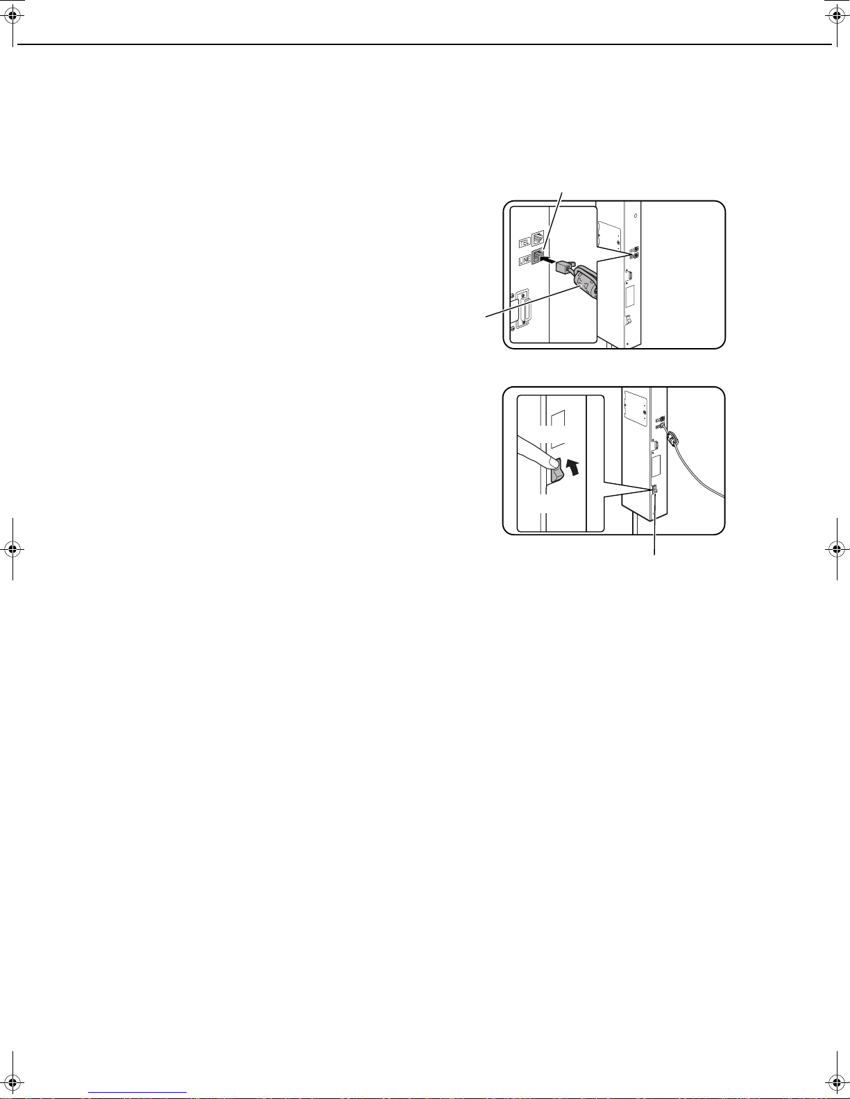
■■■■ Line connection
Use the telephone cable supplied to connect
the machine to a telephone line. Insert the end
of the line cord with the core into the LINE jack
on the machine as shown. Insert the other end
into the telephone line jack.
■■■■ Fax power switch
When using the machine, be sure to keep the fax power
switch turned on at all times. The fax power switch must be
turned on to receive faxes at night or send timer transmission
faxes at night.
Line jack
Core
ON
OFF
Fax power switch
■■■■
Setting the date and time and programming your sender's name and number
Before using the fax function, you must set the date and time and program your sender's name and number in
the machine. This procedure is explained in "POINTS TO CHECK AND PROGRAM AFTER INSTALLATION" on
page 1-2 of this manual.
■■■■ Lithium battery
A lithium battery inside the machine keeps key operator program settings for the fax function in memory.
● When the battery dies, key operator program settings will be lost. Be sure to keep a written record of the key
operator program settings.
● The life of the lithium battery is approximately 5 years if the machine power switch and fax power switch are
kept continually off.
● When the battery dies, please consult Imagistics Technical Support.
When the lithium battery dies, a message will appear in the display and the unit will no longer function.
■■■■ Other information
● If a thunderstorm occurs, we recommend that you unplug the power cord from the power outlet. Information
will be retained in memory even if the power cord is unplugged.
0-4
Page 15

TO USE THIS PRODUCT CORRECTLY AS A FACSIMILE
FCC NOTICE TO USERS
This equipment complies with Part 68 of the FCC rules and the requirements adopted by the ACTA.
On this equipment is a label that contains, among other information, a product identifier in the format
US:AAAEQ##TXXXX.
If requested, this information must be provided to the telephone company.
A plug and jack used to connect this equipment to the premises wiring and telephone network must comply with the
applicable FCC Part 68 rules and requirements adopted by the ACTA.
A compliant telephone cord and modular plug is provided with this product.
It is designed to be connected to a compatible modular jack that is also compliant. See installation instructions for
details.
This equipment connects to the telephone network through a standard USOC RJ-11C network interface jack.
The REN is used to determine the number of devices that may be connected to a telephone line.
Excessive RENs on a telephone line may result in the devices not ringing in response to an incoming call.
In most but not all areas, the sum of the RENs should not exceed five (5.0).
To be certain of the number of devices that may be connected to your line, as determined by the total RENs, contact
your local telephone company.
For products approved after July 23, 2001, the REN for this product is part of the product identifier that has the format
US:AAAEQ##TXXXX.
The digits represented by ## are the REN without a decimal point (e.g., 03 is a REN of 0.3).
For earlier products, the REN is separately shown on the label.
If this equipment causes harm to the telephone network, your telephone company may disconnect your service
temporarily.
If possible, They will notify you in advance.
If advance notice is not practical, you will be notified as soon as possible.
You will also be advised of your right to file a complaint with the FCC.
Your telephone company may make changes in its facilities, equipment, operations, or procedures that could affect
the operation of your equipment.
If this happens, the telephone company will provide advance notice in order for you to make necessary modifications
to maintain uninterrupted service.
If the equipment is causing harm to the telephone network, your telephone company may ask you to disconnect the
equipment until the problem resolved.
If you have any questions or problems which cannot be solved by reading this manual, please contact
Imagistics International Inc.
100 Oakview Drive
Trumbull, CT 06611-4784
Telephone: (203) 365-7000
This equipment may not be used on coin service provided by the telephone company.
Connection to party lines service is subject to state tariffs.
Contact your state's public utility commission, public service commission or corporation commission for more
information.
If your home has specially wired alarm equipment connected to the telephone line, ensure the installation of this
equipment does not disable your alarm equipment.
If you have questions about what will disable alarm equipment, consult your telephone company or a qualified installer.
0-5
Page 16

TO USE THIS PRODUCT CORRECTLY AS A FACSIMILE
ABOUT THE TELEPHONE CONSUMER PROTECTION ACT OF 1991
The Telephone Consumer Protection Act of 1991 makes it unlawful for any person to use a computer or other
electronic device, including FAX machines, to send any message unless such message clearly contains in a margin
at the top or bottom of each transmitted page or on the first page of the transmission, the date and time it is sent and
an identification of the business or other entity, or other individual sending the message and the telephone number
of the sending machine or such business, other entity, or individual.
(The telephone number provided may not be a 900 number or any other number for which charges exceed local or
long-distance transmission charges.)
In order to program this information into your FAX machine, you should complete the following steps:
See CHAPTER 8 of this operation manual.
IMPORTANT SAFETY INFORMATION
●
If any of your telephone equipment is not operating properly, you should immediately remove it from your telephone
line, as it may cause harm to the telephone network.
●
The AC power outlet should be installed near the equipment and should be easily accessible.
●
Never install telephone wiring during a lightning storm.
●
Never install telephone jacks in wet locations unless the jack is specifically designed for wet locations.
●
Never touch uninsulated telephone wires or terminals unless the telephone line has been disconnected at the
network interface.
●
Use caution when installing or modifying telephone lines.
●
Avoid using a telephone (other than a cordless type) during an electrical storm. There may be a remote risk of
electric shock from lightning.
●
Do not use a telephone to report a gas leak in the vicinity of the leak.
●
Do not install or use the machine near water, or when you are wet.
Take care not to spill any liquids on the machine.
0-6
Page 17

TO USE THIS PRODUCT CORRECTLY AS A FACSIMILE
NOTICE FOR USERS IN
CANADA
NOTICE : This product meets the applicable Industry
Canada technical specifications.
NOTICE : The Ringer Equivalence Number is an
indication of the maximum number of devices allowed
to be connected to a telephone interface. The
termination on an interface may consist of any
combination of devices subject only to the requirement
that the sum of the RENs of all the devices does not
exceed five.
The REN of this equipment is indicated on the label
of the equipment.
Pitney Bowes Canada Ltd.
1-800-668-9194 (voice)
1-800-465-1186 (fax)
AVIS POUR NOS
UTILISATEURS AU CANADA
AVIS : Le présent matériel est conforme aux
spécifications techniques applicables d'Industrie
Canada.
Remarque : L'indice d'équivalence de la sonnerie
(IES) sert à indiquer le nombre maximal de terminaux
qui peuvent être raccordés à une interface
téléphonique. La terminaison d'une interface peut
consister en une combinaison quelconque de
dispositifs, à la seule condition que la somme d'indices
d'équivalence de la sonnerie de tous les dispositifs
n'excède pas 5.
Le nombre REN (Ringer Equivalence Number) de
cet appareil est indiqué sur l'étiquette de l'appareil.
0-7
Page 18

Page 19

CHAPTER 1
BEFORE USING THE FAX
FEATURE
This chapter contains basic information that you should know before
using the fax function of the machine. Please read this chapter before
using the fax features.
Page
POINTS TO CHECK AND PROGRAM AFTER INSTALLATION..............1-2
CONNECTING AN EXTENSION PHONE ................................................1-2
●
CONNECTING AN EXTENSION PHONE ...................................... 1-2
A LOOK AT THE OPERATION PANEL....................................................1-3
●
FAX MODE (CONDITION SETTINGS SCREEN)........................... 1-4
ORIGINALS ..............................................................................................1-6
●
ORIGINALS THAT CAN BE FAXED............................................... 1-6
LOADING A DOCUMENT.........................................................................1-7
●
USING THE AUTOMATIC DOCUMENT FEEDER......................... 1-7
●
USING THE DOCUMENT GLASS.................................................. 1-7
CHECKING THE SIZE OF A LOADED ORIGINAL...................................1-8
●
MANUALLY SETTING THE SCANNING SIZE............................... 1-8
STORING, DELETING, AND USING ORIGINAL SIZES ..........................1-9
●
STORING OR DELETING AN ORIGINAL SIZE ............................. 1-9
●
USING A STORED ORIGINAL SIZE .............................................. 1-9
SELECTING RESOLUTION AND EXPOSURE SETTINGS.....................1-10
●
SELECTING THE RESOLUTION ................................................... 1-10
●
SELECTING THE EXPOSURE....................................................... 1-11
CONVENIENT DIALING METHODS ........................................................1-12
1-1
Page 20
POINTS TO CHECK AND PROGRAM
AFTER INSTALLATION
After installing the unit and before using it as a fax machine, check the following points and program the required
information.
■■■■ Make sure the fax power switch is turned on
In addition to the machine power switch (see page 1-17 of the "Copying operation manual"), the machine also
has a fax power switch (see "Fax power switch" on page 0-4). When using the machine, be sure to keep the fax
power switch turned on at all times.
■■■■ Make sure the correct date and time have been set
Make sure the correct date and time have been programmed in the unit (refer to page 2-12 of "Copying operation
manual"). If the date and time are wrong, please correct them.
It is important to set the correct date and time because they are used for such features as Timer Transmission
(page 3-6).
■■■■ Program the sender's name and sender's number
The name and fax number of the user of the machine is programmed in "Fax own number and name set" (page
8-5) in the key operator programs.
The programmed name and number are printed at the top of each transmitted fax page. The sender's number
is also used as an identification number when you use the Polling function to request transmission from another
fax machine (See "USING THE POLLING FUNCTION" on page 3-14).
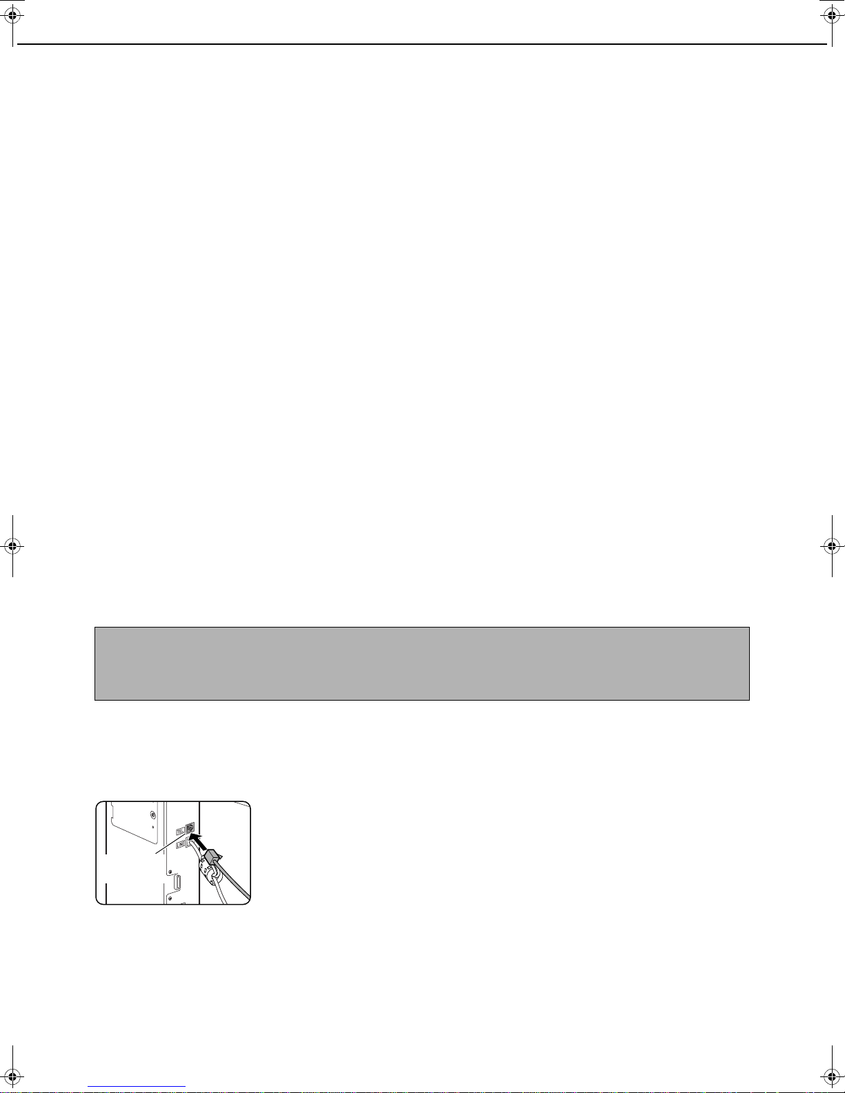
CONNECTING AN EXTENSION PHONE
You can connect a telephone to the machine and use it as an extension phone to place and receive calls like any
normal phone. When the other party has made the call, the extension phone can be used to activate fax reception.
(remote operation)
NOTES
● If you connect a combination telephone/answering machine to the machine, you will not be able to use the
answering machine function.
● You can place calls from the phone even during a power failure.
CONNECTING AN EXTENSION PHONE
Insert the end of the extension phone cord
1
into the extension phone jack on the rear
of the machine.
Make sure you hear a
"click" sound indicating
that the cord is securely
Extension
phone jack
connected.
1-2
Page 21
A LOOK AT THE OPERATION PANEL
The operation panel used for the fax function is described below.
Model Key name Description in this manual
Document filing function
added
Document filing function
not added
Describes the configuration in which
the facsimile expansion kit
(ZB3500590) and document filing
function have been installed.
No functions related to document filing
or Internet fax reception are described
in this manual.
1
Touch panel (following page)
• Messages and keys appear in the touch panel.
Touch the displayed keys to select functions and
enter settings.
• When a key in the touch panel is touched, a beep
sounds and the key is highlighted.
• Keys that cannot be selected in a screen are
grayed out. If touched, a double-beep will sound
to alert you that the key cannot be selected.
Mode select keys (page 2-2)
Use these keys to change modes.
[IMAGE SEND] key
Press to switch to fax mode. The main screen of fax
mode will appear.
The screen that appears when this key is selected
can be changed with "Default display settings" in
the key operator programs (page 8-4).
Numeric keys
Use to enter fax numbers, sub-addresses,
passcodes, and numerical settings. (See
"MEMORY BOXES AND SUB-ADDRESSES/
PASSCODES REQUIRED FOR F-CODE
TRANSMISSION" on page 4-2.)
[C] key (clear key)
Use to clear a mistake when entering fax numbers,
sub-addresses, passcodes, and numerical
settings. One digit is cleared each time you press
the key.
When an original is being scanned, this key can
also be used to cancel scanning.
[CA] key (clear all key)
Use to cancel a transmission or programming
operation. When this key is pressed, the operation
is canceled and you return to the main screen
described on the following page.
This key is also used to cancel resolution, paper
size and special mode settings.
[ ] key (page 5-3)
This is used to produce tone signals when you are
on a pulse dial line.
[START] key (page 2-3)
Press to begin scanning an original for fax
transmission.
NOTE
For the names and functions of the parts of the machine, see page 1-9 of the "Copying operation manual".
1-3
Page 22
A LOOK AT THE OPERATION PANEL
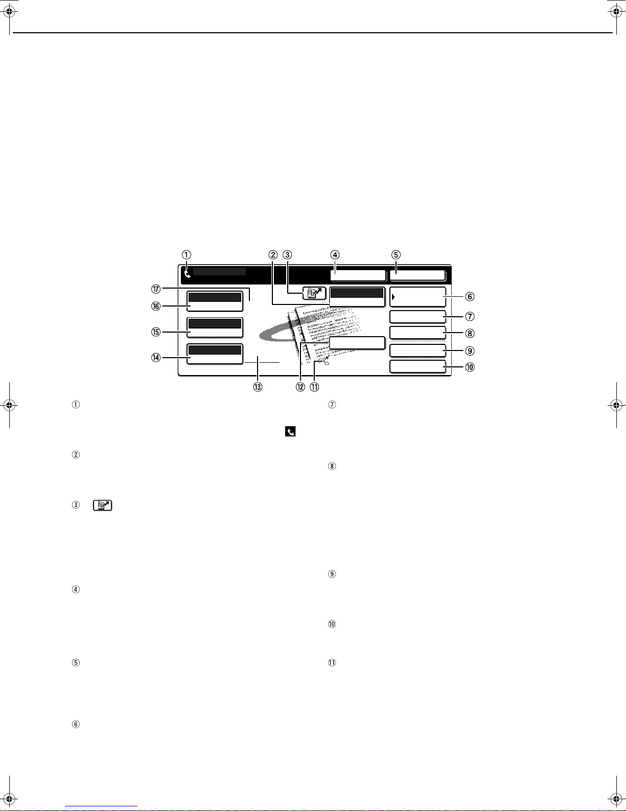
FAX MODE (CONDITION SETTINGS SCREEN)
The condition settings screen of fax mode is displayed by pressing the [IMAGE SEND] key while the document filing
mode (printer mode), copy mode, or job status screen appears in the touch panel. In the explanations that follow, it
is assumed that the initial screen that appears after pressing the [IMAGE SEND] key is the condition settings screen
(shown below). If you have set the display to show the address book screen (following page) when the [IMAGE
SEND] key is pressed, touch the [CONDITION SETTINGS] key in the address book screen to display the condition
settings screen.
"Default display settings" (page 8-4) in the key operator programs can be used to select whether the condition settings
screen (below) appears or the address book screen (next page) appears when the [IMAGE SEND] key is pressed.
•
When the network scanner option is installed, you can select whether the "E-MAIL/FTP" screen or the "INTERNET
FAX" screen appears when the [IMAGE SEND] key is pressed (the selection is made in the key operator programs).
■■■■ Condition settings screen
The display is initially set (factory setting) to show the following condition settings screen as the initial screen.
READY TO SEND.
AUTO
EXPOSURE
STANDARD
RESOLUTION
AUTO
ORIGINAL
Message display
Messages appear here to indicate the current
status of the machine. The icon at left ( )
indicates fax mode.
[MODE SWITCH] key
Use this key when the network scanner option is
installed to switch between the "E-MAIL/FTP" and
"INTERNET FAX" screens
[ ] key (Speed dial key) (page 1-12)
When a one-touch dial key or group key is stored in
the address book, the machine automatically
assigns it a 3-digit number (called a Speed Dial
number in this manual). This key and the Speed Dial
number can be used to abbreviate the transmission
procedure (see Speed Dialing on page 2-4).
[SPEAKER] key (page 1-12)
Touch the [SPEAKER] key to dial and transmit a
fax manually.
During dialing it changes into the [PAUSE] key, and
after pressing the [SUB ADDRESS] key it changes
into the [SPACE] key.
[RESEND] key (page 1-12)
Touch this key to redial the number most recently
dialed with the numeric keys or a one-touch dial
key. After dialing, this key changes into the [NEXT
ADDRESS] key.
[ADDRESS BOOK] key (page 2-4)
Touch this key to display the address book screen
(next page). Touch this key when you want to use an
auto-dial number (one-touch dialing or group dialing).
SPEAKER
FAX
MODE SWITCH
SUB ADDRESS
AUTO RECEPTION
FAX MEMORY:100%
RESEND
ADDRESS BOOK
ADDRESS REVIEW
SPECIAL MODES
FILE
QUICK FILE
[ADDRESS REVIEW] key (page 3-3)
When performing a broadcast transmission, touch
this key to check your selected destinations. The
selected destinations will appear and any
unneeded destinations can be deleted.
[SPECIAL MODES] key
Touch this key to select one of the following special
functions:
• Edge erase (page 3-4) •
•
Timer transmission (page 3-6)
• Card shot (page 3-8) •
• Polling (page 3-13) •
Dual page scan (page 3-5)
• 2in1 (page 3-7)
Job build mode (page 3-10)
Memory box (page 3-15)
• Program (page 3-17)
• Transaction report (page 3-12)
[FILE] key*
Touch this key to store a document image that you
are transmitting in the hard disk (this includes
selecting a user name, file name, and location).
[QUICK FILE] key*
Touch this key to store a document image that you
are transmitting in the temporary storage folder.
Memory and reception mode display
This shows the amount of fax memory that is free
and the currently selected reception mode.
* Can only be used when the document filing function
has been added.
1-4
Page 23
A LOOK AT THE OPERATION PANEL
A
FREQUENT USE ABCD EFGHI JKLMN OPQRST UVWXYZ
ABC
GROUP
B
C D
E F
G
H
CONDITION
SETTINGS
READY TO SEND.
ADDRESS REVIEW
RESEND
SPEAKER
GLOBAL
ADDRESS SEARCH
[SUB ADDRESS] key (page 4-3)
Touch this key to enter a sub-address and
passcode when using F-code transmission.
Two-sided scanning icon display (page 2-7)
Icons appear here when you touch the [ORIGINAL]
key and select two-sided scanning. The icons can
be touched to open function selection screens.
[ORIGINAL] key (page 1-8)
Touch this key when you wish to manually set the
size of the original to be scanned or scan both
sides of the original.
[RESOLUTION] key (page 1-10)
Touch this key to change the resolution setting for
the original to be scanned. The selected resolution
setting will be highlighted above the key. The initial
factory setting is [STANDARD].
[EXPOSURE] key (page 1-11)
Touch this key to change the exposure setting for
the original to be scanned. The selected exposure
setting will be highlighted above the key. The initial
factory setting is AUTO.
Special mode icon display (page 5-2 of
"Copying operation manual")
When a special mode such as polling or dual page
scan is selected, a special mode icon appears here.
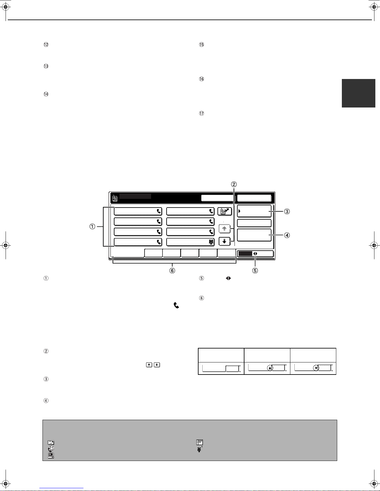
■■■■ Address book screen (alphabetically ordered)
The screen below appears initially when the address book is set as the initial screen using "Default display
settings" (page 8-4) in the key operator programs.
● The screen below is the alphabetical index screen. You can also have the user index screen initially. (See
"Default display settings" on page 8-4.)
● The screen appears as shown below when the network scanner option is not installed.
1/2
1
One-touch key display
This shows the one-touch keys that have been stored
on the selected "index card". The key type is
indicated by the icon at the right. One-touch keys in
which a fax number is stored are indicated by a " "
icon. The display is initially set to show 6 keys. This
can be changed to 8 or 12 using the key operator
program. (See "The number of direct address/sender
keys displayed setting" on page 8-4.)
Display illustrations in this manual show the display
set to eight keys.
Display switching keys
When more one-touch keys are stored than can be
displayed in one screen, touch the keys to
change screens.
[CONDITION SETTINGS] key
This displays the condition settings screen (previous
page), which is used to set various conditions.
[GLOBAL ADDRESS SEARCH] key
Touch this key to search for a fax number on an
LDAP server (page 2-5).
NOTE
When the network scanner option is installed and a destination other than a fax numbers is stored in a one-touch
key, one of the following icons will appear.
:Scan to E-mail destination :Scan to Desktop destination
:Internet fax destination :Multiple destinations (Scan to E-mail, fax, etc.)
:Scan to FTP destination
[ABC GROUP] key
Touch this key to switch between the alphabetical
index and the group index.
Index keys
One-touch key destinations are stored on each of
these index cards (alphabetical index or group
index). Each time the selected tab is touched, the
key display order changes from the order of storing
(the initial display order), to ascending order, to
descending order. As this is done, the icon on the
tab indicates the current display order.
Storing order
(initially selected)
FREQUENT USE ABCD
Ascending order Descending order
FREQUENT USE ABCD FREQUENT USE ABCD
Group indexes make it possible to store one-touch
keys by group with an assigned name for easy
reference. This is done with the custom settings
(refer to pages 6-3 and 6-9). Frequently used onetouch key destinations can be stored on the
FREQUENT USE card for convenient access.
1-5
Page 24
ORIGINALS
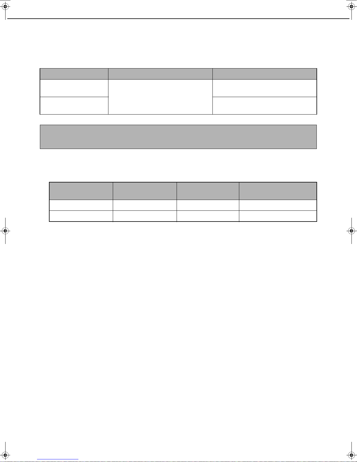
ORIGINALS THAT CAN BE FAXED
■■■■ Original sizes
Minimum original size Maximum original size
Using the automatic
document feeder
Using the document glass
NOTE
Originals that are not a standard size (5-1/2"x8-1/2", 8-1/2"x11", 8-1/2"x11"R, 8-1/2"x14", 11"x17", A5, B5, B5R,
A4, A4R, B4, A3) can also be faxed.
8-1/2" (width) x 5-1/2" (length)
(A5: 210 mm (width) x 148 mm (length))
5-1/2" (width) x 8-1/2" (length)
(A5R: 148 mm (width) x 210 mm (length))
11" (width) x 31-1/2" (length)
(297 mm (width) x 800 mm (length))
11" (width) x 17" (length)
(297 mm (width) x 431.8 mm (length))
■■■■ Automatic reduction of faxed document
If the size (width) of the faxed document is greater than the receiving machine's paper size, the size will be
automatically reduced.
Faxed document width
11"x17" (A3) 8-1/2"x14" (B4) 8-1/2"x14" (B4) 1 : 0.64 (1 : 0.78)
11"x17" (A3) 8-1/2"x11" (A4) 8-1/2"x11"R (A4R) 1 : 0.5 (1 : 0.5)
A document can also be faxed without reducing its size. In this case, the left and right edges will not be
transmitted. (See "Auto reduction sending setting" on page 8-7.)
Receiving machine's
paper width
Reduced size Ratio (Area ratio)
1-6
Page 25
LOADING A DOCUMENT
A document can be loaded in the automatic document feeder or on the document glass. Use the automatic document
feeder when faxing a large number of sheet originals. Use the document glass to fax originals that cannot be scanned
using the automatic document feeder such as thick or thin sheet originals or bound originals such as books.
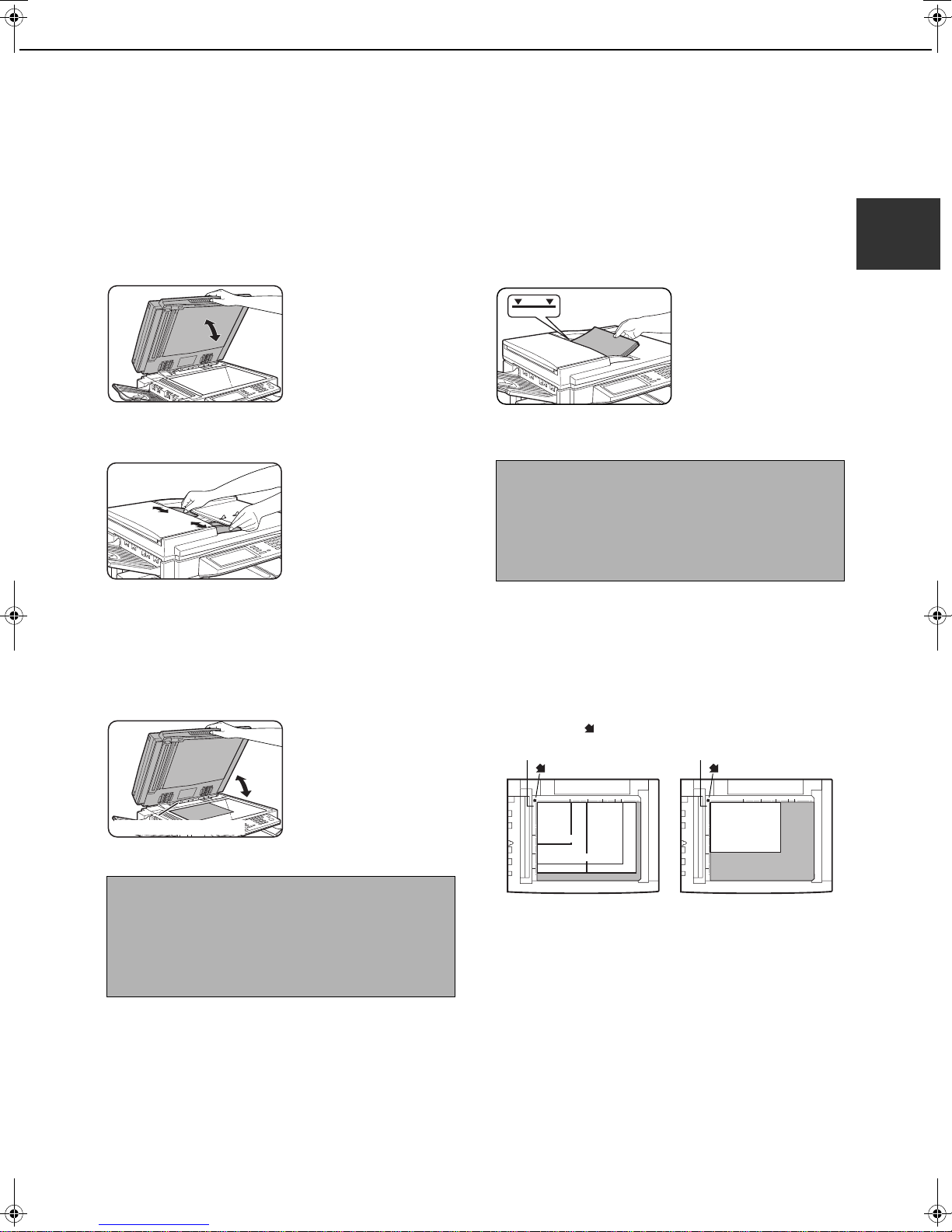
USING THE AUTOMATIC DOCUMENT FEEDER
Lift the document glass cover and make
1
sure a document is not placed on the
document glass. Gently close the cover.
Adjust the document guides on the automatic
2
document feeder to the width of the document.
3
USING THE DOCUMENT GLASS
Open the document glass cover, and place
1
the document face down on the document
glass. Gently close the cover.
Regardless of the size of the original, place the
original in the far left corner of the document glass.
(Align the upper left-hand corner of the original with
the tip of the mark.)
Align the edges of the document pages
and then insert the stack in the document
feeder so that the first page is face down.
Insert the stack into the
automatic document
feeder until it stops. The
stack should not be
higher than the indicator
line (maximum 50
pages, or 30 pages for 81/2"x14" or larger
documents).
NOTES
● Use the automatic document feeder for long
originals. The document glass cannot be used.
● When faxing a long original, touch the [LONG
SIZE] key in step 3 of "MANUALLY SETTING THE
SCANNING SIZE" (page 1-8).
Document glass scale
mark
Document glass scale
mark
1
Original size detector
NOTE
Do not place any objects under the original size
detector plate. Closing the document glass cover
with an object underneath may damage the original
size detector plate and prevent correct detection of
the document size.
5-1/2"x8-1/2"
8-1/2"x11"
8-1/2"x14"
11"x17"
8-1/2"x11"R
1-7
Page 26
CHECKING THE SIZE OF A LOADED ORIGINAL
AUTO 8 X11
ORIGINAL
STANDARD
RESOLUTION
AUTO 8 X11
ORIGINAL
STANDARD
RESOLUTION
SPEAKER
SEND SIZE
100%
AUTO
SCAN SIZE
AUTO
8 X11
2-SIDED
BOOKLET
2-SIDED
TABLET
RESEND
LONG SIZE
SPEAKER
STANDARD SIZE
AB
OK
INCH
SIZE INPUT
5 X8
5 X8 R
8 X11
8 X13
8 X14
11X17
8 X11R
AUTO
MANUAL
8 X11
A5
A5R
A5
B5
B5R
A4R
A4
B4
A3
RESEND
LONG SIZE
SPEAKER
INCH
OK
AB
SIZE INPUTSTANDARD SIZE
17
11
(2 1/2 17)
inch
STANDARD SIZE
Y
X
A
X
Y
SIZE INPUT
OK
OK
RESENDSPEAKER
SEND SIZE
AUTO
-SIDED
ORIGINAL
STANDARD
RESOLUTION
When a standard-size* original is placed, the original size is automatically detected
(automatic original detection function) and displayed in the top half of the [ORIGINAL]
key. Check the key to make sure that the original size has been correctly detected.
:[AUTO] appears when the automatic original detection function is operating.
:Displays the original size.
If a non-standard size original is placed or if you wish to change the scanning size,
follow the steps below to manually set the original scanning size.
NOTE
*
Standard sizes that can be detected are as follows:
5-1/2"x8-1/2", 8-1/2"x11", 8-1/2"x11"R, 8-1/2"x14", 11"x17", A5, B5, B5R, A4, A4R, B4, A3. If a non-standard
size original is loaded (including special sizes), the closest standard size may be displayed, or the original size
may not appear at all.
MANUALLY SETTING THE SCANNING SIZE
If you load an original that is not a standard size (such as an AB size), or if the size is not detected correctly, you must
touch the [ORIGINAL] key and set the original size manually. Perform the following steps after loading the document
in the automatic document feeder or on the document glass.
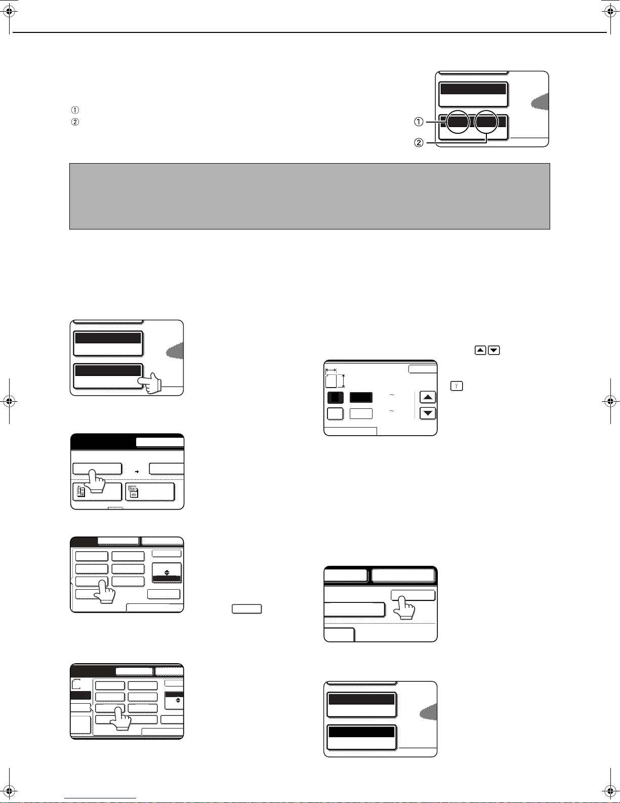
Touch the [ORIGINAL] key.
1
If the address book screen
appears, touch the
[CONDITION SETTINGS]
key to display the
1
/
2
condition settings screen
(page 1-5).
Touch the key under [SCAN SIZE].
2
1
/
2
If you placed a non-standard size original
on the document holder or on the
document glass, touch the [SIZE INPUT]
tab and then enter the width (X) and length
(Y) of the original with the keys.
X (width) is initially selected.
Enter X and then touch the Y
( ) key to enter Y. A width of
2-1/2 to 17 inch (64 to 432 mm)
(2 1/2 11 5/8)
inch
If you frequently send documents that are the same nonstandard size, you can store the dimensions as explained
in "STORING, DELETING, AND USING ORIGINAL
SIZES" on the following page. This will allow you to omit
entry of X and Y each time you send that size of document.
can be entered in X, and a
length of 2-1/2 to 11-5/8 inch (64
to 297 mm) can be entered in Y.
1
/
2
Touch the desired original size key.
3
[AUTO] is no longer
1
/
2
1
/
2
1
/
2
1
/
2
1
1
/
/
2
2
1
1
/
/
2
2
highlighted. [MANUAL]
and the original size key
you touched are
highlighted.
If you placed a long original,
touch the key.
If you wish to select an AB size, touch the
[AB/INCH] key and then touch the desired
original size key.
[AB] is highlighted and
1
/
2
1-8
AB size keys are
displayed. To return to
the inch palette, touch
the [AB/INCH] key once
again.
LONG SIZE
Touch the outer [OK] key.
4
Touch the [OK] key to return to the screen of step 2.
Touch the outer [OK] key.
5
The selected size appears in the top half of
6
the [ORIGINAL] key.
A4
Page 27
STORING, DELETING, AND USING ORIGINAL SIZES
AUTO 8 X11
ORIGINAL
STANDARD
RESOLUTION
100%
SCAN SIZE
AUTO 8 X11
2-SIDED
BOOKLET
2-S
TAB
CUSTOM
SIZE
STANDARD SI
MANUAL
5 X8 R
5 X8
5R
RECALL
STORE/DELETE
RECALL
STORE/DELETE
CANCEL OK
17
11
(2 1/2 17)
inch
RECALL
Y
X
A
X
Y
STORE/DELETE
(2 1/2 11 5/8)
inch
RECALL
STORE/DELETE
Up to 9 special original sizes can be stored. Stored sizes can be easily called up and are not erased if the power is
turned off. Storing a frequently used original size saves you the trouble of manually setting the size each time you
fax that size of document.
●
To cancel an original size storing, using, or deleting operation, press the [CA] key or touch the [ORIGINAL] key
on the screen.
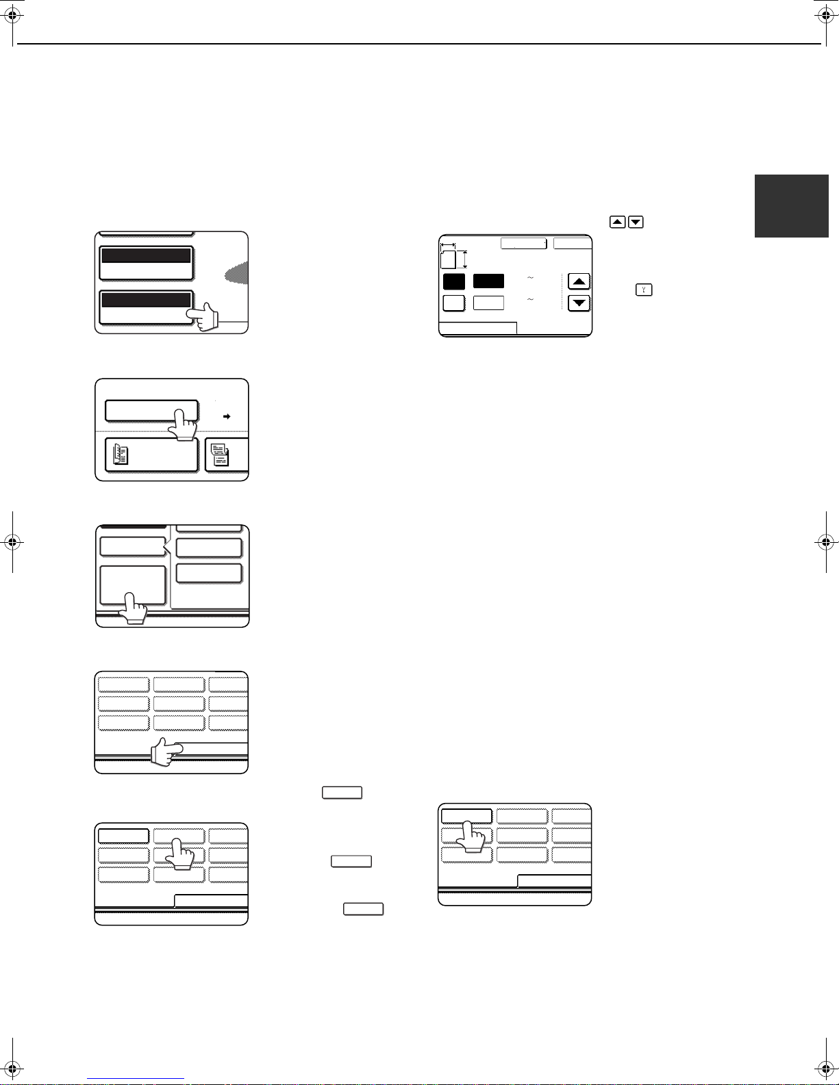
STORING OR DELETING AN ORIGINAL SIZE
Touch the [ORIGINAL] key.
1
1
/
2
Touch the key under [SCAN SIZE].
2
1
/
2
Touch the [CUSTOM SIZE] key.
3
1
1
/
/
2
2
1
1
/
/
2
2
Enter the X (width) and Y (length) dimensions
6
of the original with the keys.
X (width) is initially
selected.
Enter X and then touch
the ( ) key to enter Y.
A width of 2-1/2 to 17
inch (64 to 432 mm) can
be entered in X, and a
length of 2-1/2 to 11-5/8 inch (64 to 297 mm) can
be entered in Y.
Touch the [OK] key.
7
The original size entered in step 6 is stored in the
key selected in step 5.
To exit, touch the [ORIGINAL] key.
When you touch a key that shows an
8
original size in step 5, a message screen
appears that contains the keys [CANCEL],
[DELETE], and [AMEND].
● To cancel the procedure, touch the [CANCEL] key.
● To delete the selected original size, touch the
[DELETE] key.
● To change the original size stored in the key, touch
the [AMEND] key. The screen of step 6 will appear
to let you change the size.
1
Touch the [STORE/DELETE] key.
4
Touch the original size key ( ) that
5
you wish to store or delete.
1
/
2
X5 Y10
1
/
8
To store an original size,
touch a key that does not
show a size ( ).
Keys that already have an
original size stored will show
the stored size ( ).
To delete or change a
stored size, touch the key that shows the size that you
wish to delete or change.
●
If you are storing an original size, go to step 6.
●
●
If you are deleting an original size, go to step 8.
If you are changing an original size, go to step 8
and touch the [AMEND] key.
1
/
X5 Y10
2
To exit, touch the [ORIGINAL] key.
9
USING A STORED ORIGINAL SIZE
Follow steps 1 to 3 of "STORING OR
1
DELETING AN ORIGINAL SIZE".
Touch the original size key that you wish
2
to use.
1
1
/
/
X5 Y10
2
8
1
/
8
Touch the [OK] key.
3
The stored original size is called up.
1-9
Page 28
SELECTING RESOLUTION AND EXPOSURE SETTINGS
AUTO 8 X11
ORIGINAL
STANDARD
RESOLUTION
STANDARD
FINE
SUPER FINE HALF TONE
ULTRA FINE
FINE
HALF TONE
OK
FINE
After loading an original, you can adjust the resolution and exposure settings to match the condition of the originalfor example, if it has small or faint characters, or if it is a photo. After loading the original in fax mode, adjust the
settings as explained below.
SELECTING THE RESOLUTION
The initial resolution setting is STANDARD. To change the setting, follow these steps:
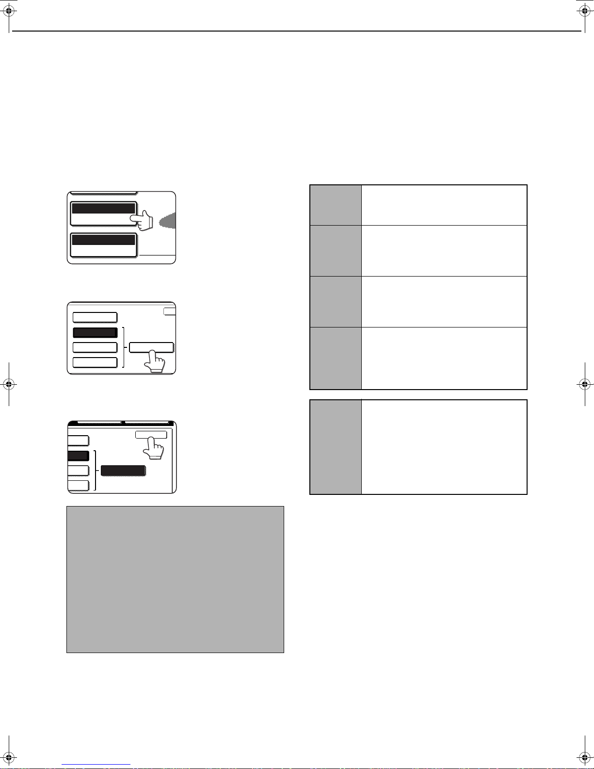
■■■■ Change the resolution.
Touch the [RESOLUTION] key.
1
■■■■ Resolution settings
Touch this key if your original consists
Standard
of normal-sized characters (like those
in this manual).
1
/
2
Touch the [STANDARD] key, [FINE] key,
2
[SUPER FINE] key, or [ULTRA FINE] key.
The selected key is
highlighted.
If you touched the [FINE]
key, [SUPER FINE] key,
or [ULTRA FINE] key,
you can also select
halftone by touching the
[HALF TONE] key.
Touch the [OK] key.
3
You will return to the
initial screen.
NOTES
The factory default setting for the initial resolution is
●
[STANDARD]. The initial resolution can be changed
to a different setting in the key operator programs
(see "Initial resolution setting" on page 8-4).
● When using the automatic document feeder, the
resolution setting cannot be changed once
scanning has begun.
● When a fax is sent at [ULTRA FINE], [SUPER
FINE], or [FINE] resolution, a lower resolution will
be used if the receiving machine does not have
that resolution.
Fine
Super fine
Ultra fine
Half tone
Touch this key if your original has small
characters or diagrams. The original
will be scanned at twice the resolution
of the
[STANDARD]
Touch this key if your original has
intricate pictures or diagrams. A higherquality image will be produced than
with the [FINE] setting.
Touch this key if your original has
intricate pictures or diagrams. This
setting gives the best image quality.
However, transmission will take longer
than with the other settings.
Touch this key if your original is a
photograph or has gradations of color
(such as a color original). This setting
will produce a clearer image than
[FINE], [SUPER FINE], or [ULTRA
FINE] used alone. Half tone cannot be
selected if [STANDARD] has been
selected.
setting.
1-10
Page 29
SELECTING RESOLUTION AND EXPOSURE SETTINGS
AUTO
ORIGINAL
STANDARD
RESOLUTION
AUTO
EXPOSURE
AUTO MANUAL
MANUALAUTO
OK
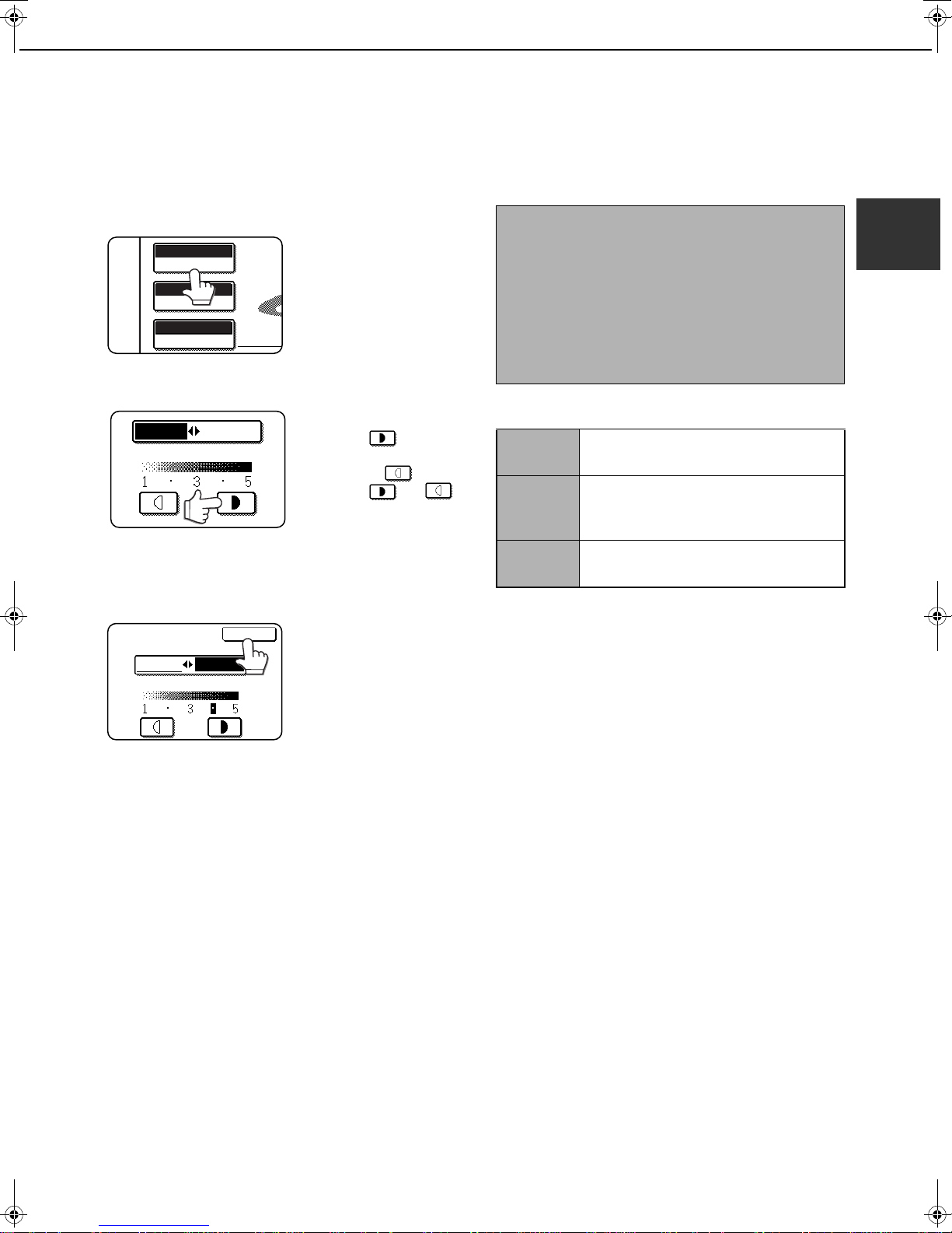
SELECTING THE EXPOSURE
The initial exposure setting is AUTO. To change the setting, follow these steps:
■■■■ Change the exposure.
Touch the [EXPOSURE] key.
1
Touch the desired exposure key.
2
To darken the exposure,
touch the key. To
lighten the exposure,
touch the key.
When the or
key is touched, [AUTO]
is not highlighted and
[MANUAL] is highlighted. To return to auto
exposure, touch [AUTO].
Touch the [OK] key.
3
You will return to the
initial screen.
NOTES
● When using the document glass to scan pages an
original, the exposure setting can be changed
each time you change pages. When using the
automatic document feeder, the exposure setting
cannot be changed once scanning has begun.
● The default (initial) exposure setting can be
changed in "Default exposure settings" (page 8-5)
in the key operator programs.
■■■■ Exposure settings
1 to 2
Auto
4 to 5
Select this setting if your original consists
Originalmostly of dark characters.
This setting automatically adjusts the
exposure for light and dark parts of the
original.
Select this setting if your original consists
Originalmostly of faint characters.
1
1-11
Page 30
CONVENIENT DIALING METHODS
FREQUENT USE ABCD EFGHI JKLMN OPQRS
CORPO.TPS
ABCD GROUP
ABCD CORPORATION
ABCD CORPORATION
0666211221
ABCD CORPORATION
FREQUENT USE ABCD EFGHI JKLMN OPQRST
CORPO.TPS
ABCD GROUP
ABCD GROUP
GROUP:025
SPEAKER
RESENDPEAKER
SWITCH
ADDRESS BOOK
ADDRESS REVIEW
RESSPEAKER
MODE SWITCH
FAX
ADDRES
ADDRESS
The fax function includes a convenient auto dial feature (one-touch dialing and group dialing). By programming
frequently dialed numbers, you can call and send documents to these locations by means of a simple dialing
operation (refer to page 2-4). There are two types of auto-dialing: one-touch dialing and group dialing. To program
auto-dial numbers, refer to pages 6-3, 6-6.
● One-touch dialing
Simply press a one-touch key and then press the [Start]
key to dial the programmed location. A name of up to 36
characters can be programmed for the location (a
maximum of 18 characters are displayed). When using Fcode transmission, a sub-address and passcode can also
be programmed (refer to page 4-2).
● Group dialing
Multiple one-touch dial locations can be programmed into
a single one-touch key. This is convenient for successively
sending a document to multiple locations.
• Full fax numbers entered with the numeric keys can also
be stored in group keys.
● Speed dialing
When a one-touch key or group key is stored in the
address book, the machine automatically assigns it a 3digit speed dial number.
The key and 3-digit Speed Dial number can be used
to abbreviate the transmission procedure.
● Redialing
The machine keeps the last fax number dialed with the
numeric keys in memory. You can redial the last number
dialed by simply touching the [RESEND] key.
• If numeric keys were pressed during a phone
conversation, the [RESEND] key may not dial the correct
number.
• If the previous transmission was a broadcast
transmission in which one-touch keys were used, the
[RESEND] key cannot be used.
Touch the
[ADDRESS] key in
the initial screen to
display the left
screen.
Touch the
[ADDRESS] key in
the initial screen to
display the left
screen.
● On-hook dialing
This is a dialing function. This feature allows you to dial
without lifting an extension phone connected to the
machine. Touch the [SPEAKER] key, listen for the dial
tone through the speaker, and then dial.
• Faxes must be sent manually when using on-hook dialing.
• On-hook dialing is not possible using a one-touch key that
includes a sub-address and passcode, or a group dial key.
NOTES
● Programmed one-touch keys and group dial keys are stored on "index cards". A one-touch key or group key can
be easily accessed by touching the index key. (Refer to on page 1-5.)
● To prevent calling or sending a fax to a wrong number, look carefully at the touch panel and make sure you
program the correct number when programming an auto-dial number. After storing a number, you can also print
out the stored number (Refer to page 6-14) to make sure it was stored correctly.
1-12
Page 31

CHAPTER 2
BASIC OPERATIONS
This chapter explains basic operations such as sending faxes.
Page
SENDING A FAX .................................................................................... 2-2
●
BASIC PROCEDURE FOR SENDING FAXES............................... 2-2
●
TRANSMISSION BY AUTO-DIALING (ONE-TOUCH DIALING
AND GROUP DIALING).................................................................. 2-4
●
SENDING A FAX BY SPEED DIALING.......................................... 2-4
●
FAX NUMBER ENTRY WITH GLOBAL ADDRESS SEARCH ....... 2-5
●
ENLARGING/REDUCING THE IMAGE BEFORE TRANSMISSION
●
FAXING A TWO-SIDED ORIGINAL................................................ 2-7
PRIORITY TRANSMISSION OF A STORED JOB ................................. 2-9
CANCELING A FAX TRANSMISSION ................................................... 2-9
●
CANCELING ON-HOOK DIALING.................................................. 2-9
RECEIVING FAXES ............................................................................... 2-10
●
RECEIVING A FAX......................................................................... 2-10
... 2-6
2-1
Page 32

SENDING A FAX
FAX
E-MAIL/FTP
MODE SWITCH
INTERNET FAX
SPEAKER
MODE SWITCH
FAX
AUTO 8 X11
ORIGINAL
STANDARD
RESOLUTION
AUTO 8 X11
ORIGINAL
STANDARD
RESOLUTION
AUTO
ORIGINAL
STANDARD
RESOLUTION
AUTO
EXPOSURE
TION
QUICK FILE
SPECIAL MODES
FILE
DDRESS REVIEW
BASIC PROCEDURE FOR SENDING FAXES
Make sure the machine is in fax mode.
1
When the [IMAGE
SEND] key light is on,
the machine is in fax
mode. If the light is not
on, press the [IMAGE
SEND] key.
If the network scanner
option is installed, touch
the [MODE SWITCH]
key and then the [FAX]
key to switch to fax
mode.
When fax mode is
selected, "FAX" appears
in the top half of the
[MODE SWITCH] key.
Load the original.
2
●
Using the automatic document feeder: Page 1-7
●Using the document glass: Page 1-7
If you are using the document glass to send
multiple pages, load the first page first.
NOTE
You cannot load documents in both the automatic
document feeder and on the document glass and
send them in a single fax transmission.
Check the original size.
3
If the address book
screen appears, touch
the [CONDITION
1
/
2
If the original is not a standard size or the size was
not detected correctly, touch the [ORIGINAL] key
to specify the original size. (See "MANUALLY
SETTING THE SCANNING SIZE" on page 1-8.)
SETTINGS] key to
display the condition
settings screen (page
1-5).
If needed, adjust the resolution setting.
4
(Refer to page 1-10.)
1
/
2
If needed, adjust the exposure setting.
5
(Refer to page 1-11.)
If desired, touch the [FILE] key or the
6
[QUICK FILE] key.*
* Can only be used when the document filing
function has been added.
These keys are used to
store the scanned image
in the machine's hard
disk. The stored image
can be printed or
transmitted again at a
later time.
For information on this function, see "Document
filing functions" in chapter 7 of the Copying
operation manual.
If the [FILE] key is grayed out, only the [QUICK
FILE] key can be selected.
When you touch the [QUICK FILE] key, a
message asking you to confirm the save will
appear. Touch the [OK] key in the message
screen and go to the next step.
If you wish to cancel the save, touch the [QUICK
FILE] key after touching the [OK] key so that the
[QUICK FILE] key is no longer highlighted.
2-2
Page 33

SENDING A FAX
NEPAUSE
MODE SWITCH
FAX
ADDR
ADDRESS
READ-END
Dial the fax number.
7
The number that you
entered appears in the
message display (See
"Condition settings
screen" on page 1-4.). If
it is not correct, press the
[C] key and re-enter the
number. You can also use the [RESEND] key
(page 1-12) or an auto-dial number (following
page).
Using the automatic document feeder Using the document glass
Press the [START] key.
8
Scanning begins.
If there are no previous
jobs in progress and the
line is free, the machine
will dial the receiving
machine and begin
transmission as soon as
the first page is
scanned. Transmission will take place while any
remaining pages are scanned (Quick on-line
transmission: see page 2-8).
If there is a previously stored job or a job is in
progress, or if the line is being used, all pages of
the document are scanned into memory and
stored as a transmission job. (This is called
memory transmission: the destination is
automatically called and the document transmitted
after previously stored jobs are completed.)
If scanning is completed normally, the machine
makes a beep sound to inform you that the
transmission job is stored and "JOB STORED."
appears in the message display.
Entering a pause.
Each time you touch the [PAUSE] key, a hyphen ("-")
appears and a 2-second pause* is inserted.
The [PAUSE] key is also be used to link numbers
together (this is called chain dialing). Enter a number,
touch the [PAUSE] key to enter a hyphen "-", and then
enter another number with the numeric keys or by
pressing a one-touch key. The linked numbers will be
dialed as one number.
* The duration of each pause can be changed with
the key operator program. ("Pause time setting" on
page 8-6.)
Press the [START] key.
8
If you have another page to scan, change
9
pages and then press the [START] key.
Repeat this sequence until all pages have been scanned.
You can change the resolution and exposure settings as
needed for each page (refer to pages 1-10 and 1-11).
If the [START] key is not pressed within approximately
one minute, scanning will end automatically and the
transmission will be stored.
After the last page is scanned, touch the
10
[READ-END] key.
previously stored jobs are completed.) Open the
document glass cover and remove the document.
If you need to insert a
pause between digits
when dialing out from a
PBX or when dialing an
international number,
touch the [PAUSE] key in
the upper right corner of
the screen.
The original is scanned
and the [READ-END]
key appears in the touch
panel.
The machine makes a beep
sound to inform you that the
transmission job is stored
and
"
appears in the message
display. (The destination is
automatically called and the
document transmitted after
JOB STORED.
2
"
NOTES
●●●● Canceling transmission
To cancel transmission while "SCANNING ORIGINAL..." appears in the display or before the [READ-END] key
is pressed, press the [C] key or the [CA] key. To cancel a transmission job that is already stored, press the [JOB
STATUS] key and cancel the job as explained on page 2-9.
● If the machine makes two beeps during or at the end of transmission and an error message appears in the
message display, refer to page 7-3 to fix the problem.
● If the power is turned off or a power failure occurs while a document is being scanned in the automatic document
feeder, the machine will stop and a document jam will occur. After power is restored, remove the document as
explained on page 2-22 of "Copying operation manual".
● A job number appears in the display with "JOB STORED." when a transmission job is stored. If you make a note
of this number, you can use the number to easily locate the job when checking the results of the transmission
in the job status screen for a broadcast transmission, or in the transaction report (page 7-2) or activity report
(page 7-3) for other types of transmission jobs.
2-3
Page 34

SENDING A FAX
RESENDPEAKER
SWITCH
ADDRESS BOOK
ADDRESS REVIEW
FREQUENT USE ABCD EFGHI JKLMN OPQRS
CORPO.TPS
ABCD GROUP
S
ABCD CORPORATION
READY TO SEND.
SPEAKER
MODE SWITCH
FAX
TRANSMISSION BY AUTO-DIALING
(ONE-TOUCH DIALING AND GROUP DIALING)
Fax numbers can also be dialed by automatic dialing (one-touch dialing and group dialing). Follow the steps below
to send a fax using an auto dial number. To use an auto dial number, the name and fax number of the destination
must first be stored. For information on auto dial numbers, see page 1-12. To store an auto dial number, see pages
6-3 and 6-6.
Perform steps 1 through 6 of "BASIC
1
PROCEDURE FOR SENDING FAXES"
(page 2-2).
Touch the [ADDRESS BOOK] key.
2
The address book
screen appears.
This step is not
necessary if the address
book already appears.
Go to step 3.
Touch the one-touch key for the desired
3
destination.
Refer to page 1-5 for
information on using the
address book screen.
The key you touched is
highlighted. If you touch
the wrong key, touch the
key again to cancel the
selection. The key display will return to normal.
Continue from step 8 of "BASIC
4
PROCEDURE FOR SENDING FAXES"
(page 2-3).
SENDING A FAX BY SPEED DIALING
In addition to one-touch dialing and group dialing, you can also send a fax by touching the key (Speed Dial key)
and entering a 3-digit Speed Dial number. Follow the steps below to send a fax by Speed Dialing. The 3-digit Speed
Dial number is automatically assigned by the machine when a one-touch key or group key is stored. (See Speed Dial
numbers on pages 6-3 and 6-6.)
Perform steps 1 through 6 of "BASIC
1
PROCEDURE FOR SENDING FAXES"
(page 2-2).
Touch the key (Speed Dial key).
2
Enter the 3-digit Speed Dial number.
3
Enter the 3-digit Speed
Dial number that was
automatically assigned
by the machine when
the destination was
stored in a one-touch
key or a group key. (See
Speed Dial numbers on pages 6-3 and 6-6.)
Zeros at the beginning of the number (such as
001) can be omitted. Touch the key (Speed
Dial key).
If you enter the wrong number, press the [C] key to
clear it. If you enter a 3-digit number that is not
stored in the machine, press the [C] and then enter
the correct number. If you do not know the 3-digit
number, print the stored destination list (See
"PRINTING PROGRAMMED INFORMATION" on
page 6-14.)
2-4
Continue from step 8 of "BASIC
4
PROCEDURE FOR SENDING FAXES"
(page 2-3).
Page 35

SENDING A FAX
ABC GROUP
GLOBAL
ADDRESS SEARCH
S TTINGS
ADDRESS REVIEW
1/2
CANCEL
OK
k
l
@
i
o
p
_
CANCEL SEARCH
tanaka
tanaka a
06-612
06-623
tanaka b
tanaka c
06-634
FAX NUMBER ENTRY WITH GLOBAL ADDRESS SEARCH
If the machine is configured as a network printer that can use LDAP service, the machine can be used to access the
LDAP server* and search for the fax number. If the search returns the desired fax number, the number can be
selected as a destination fax number and/or stored in the address book.
* The LDAP server must be available for use and a fax number search service must be in operation.
Touch the [GLOBAL ADDRESS SEARCH]
1
key.
The server change
screen is displayed. If
only one LDAP server
has been set, the global
address search screen
is displayed. Proceed to
step 4.
Touch the desired LDAP server key.
2
SERVER CHANGE
Document division 1
Document division 2
A1210 project team
Software development center
CANCEL
OK
1/2
To search the highlighted server, proceed to step
3.
Touch the [OK] key.
3
Enter a keyword for search.
4
GLOBAL ADDRESS SEARCH
CANCEL SEARCH
Touch the [SEARCH] key.
5
The search results
appear as destination
keys.
READY TO SEND.
ADD SELECTED
tanaka
tanaka a
tanaka b
tanaka c
DETAIL
06-6123-456X
06-6234-567X
06-6345-678X
CONDITION
SETTINGS
ADDRESS REVIEW
SEARCH AGAIN
ADDRESS BOOK
If matching addresses are not found, a message
indicating the result is displayed. In this case,
touch the [OK] key and touch the [SEARCH
AGAIN] key to return to step 4.
Touch the desired destination key.
6
To display the remaining
destinations, touch the
[ ] key.
For detailed information
on the selected
destination, touch the
[DETAIL] key. You can
also register the
destination fax number to the address book by
touching the [REGISTER] key.
2
w
q
s
a
x
z
e
d
c
r t y
f g h
v
b n m
SPACE
u
j
i
k
-
AB/ab
o
l
.
12#$
p
@
_
abc
ABC
ÀÄÂ/àäâ
2-5
Page 36

SENDING A FAX
FAX
E-MAIL/FTP
MODE SWITCH
INTERNET FAX
SPEAKER
MODE SWITCH
FAX
RESOLUTION
AUTO 11X17
ORIGINAL
2-SIDED
BOOKLET
2TA
AUTO 11X17
SCAN SIZE
100%
SEND SIZE
2-SIDED
TABLET
8 X13
5 X8
5 X8 R
1
/
2
1
/
2
1
/
2
1
/
2
8 X11
1
/
2
8 X11R
1
/
2
1
/
2
8 X14
1
/
2
11X17
OK
SEND SIZE
70%
8 X13
2-SIDED
TABLET
SPEAKER RESEND
ENLARGING/REDUCING THE IMAGE BEFORE TRANSMISSION
Follow these steps to enlarge or reduce the scanned image before transmission.
Make sure the machine is in fax mode.
1
When the [IMAGE
SEND] key light is on,
the machine is in fax
mode. If the light is not
on, press the [IMAGE
SEND] key.
If the network scanner
option is installed, touch
the [MODE SWITCH]
key and then the [FAX]
key to switch to fax
mode.
When fax mode is
selected, "FAX" appears
in the top half of the
[MODE SWITCH] key.
Load the original.
2
●
Using the automatic document feeder: Page 1-7
●Using the document glass: Page 1-7
If you are using the document glass to send
multiple pages, load the first page first.
NOTE
You cannot load documents in both the automatic
document feeder and on the document glass and
send them in a single fax transmission.
Touch the [ORIGINAL] key.
3
Check the original size.
4
If the original size has not
been correctly detected,
touch the key under
[SCAN SIZE] and specify
the original size. (See
"MANUALLY SETTING
THE SCANNING SIZE"
on page 1-8)
NOTE
A long size, stored size, or non-standard size cannot
be specified for the original scanning size.
Touch the key under [SEND SIZE].
5
If the key under [SEND
AUTO
SIZE] is grayed out,
specify a standard
original size in step 4.
Touch the key of the desired enlargement
6
or reduction size.
The [AUTO] key is no
longer highlighted. The
[MANUAL] key and the
selected size key are
highlighted.
Touch the OK key.
7
Check the enlargement or reduction ratio
8
and touch the [OK] key.
2-6
1
/
2
Continue from step 4 of "BASIC
9
PROCEDURE FOR SENDING FAXES"
(pages 2-2 to 2-3).
NOTE
After the transmission is stored, the [CA] key can be
pressed to cancel enlargement/reduction transmission.
Page 37

SENDING A FAX
FAX
E-MAIL/FTP
MODE SWITCH
INTERNET FAX
SPEAKER
MODE SWITCH
FAX
AUTO 8 X11
ORIGINAL
STANDARD
RESOLUTION
SEND
100%
STORE
AUTO 8 X11
2-SIDED
BOOKLET
2-SIDE
TABLET
RESEND
OK
KER
AUTO
AUTO 8 X11
ORIGINAL
STANDARD
RESOLUTION
FAXING A TWO-SIDED ORIGINAL
A two-sided document can be automatically transmitted using the automatic document feeder. Follow the steps
below to automatically send a two-sided document.
Make sure the machine is in fax mode.
1
When the [IMAGE
SEND] key light is on,
the machine is in fax
mode. If the light is not
on, press the [IMAGE
SEND] key.
Touch the [2-SIDED BOOKLET] key or the
4
[2-SIDED TABLET] key as appropriate for
the original you loaded.
1
/
2
If the network scanner
option is installed, touch
the [MODE SWITCH]
key and then the [FAX]
key to switch to fax
mode.
When fax mode is
selected, "FAX" appears
in the top half of the
[MODE SWITCH] key.
Place the original in the automatic
2
document feeder (see "USING THE
AUTOMATIC DOCUMENT FEEDER" on
page 1-7) .
Touch the [ORIGINAL] key.
3
If the address book
screen appears, touch
the [CONDITION
1
/
2
When you touch the [ORIGINAL] key, check the
original size that appears in the key. If the size was
not detected correctly, specify the correct size.
(See "MANUALLY SETTING THE SCANNING
SIZE" on page 1-8.)
SETTINGS] key to
display the condition
settings screen (see
page 1-5).
Touch the [OK] key.
5
You will return to the
initial screen.
A two-sided original icon
appears next to the
[ORIGINAL] key.
Example:
The icon that appears
when the [2-SIDED
BOOKLET] key is
1
/
2
Continue from step 4 of "BASIC
6
PROCEDURE FOR SENDING FAXES"
touched.
(pages 2-2 to 2-3).
2
NOTES
● Booklets and tablets
Two-sided originals that are bound at the side are booklets, and two-sided
originals that are bound at the top are tablets.
● Two-sided scanning turns off after the document is stored in memory.
Pressing the [CA] key will also cancel two-sided scanning.
Booklet Tablet
2-7
Page 38

SENDING A FAX
■■■■ Quick On-line
When you use the automatic document feeder to send a multi-page document and there are no previously stored
jobs waiting or in progress (and the line is not being used), the machine dials the destination after the first page
is scanned and begins transmitting scanned pages while the remaining pages are being scanned. This
transmission method is called Quick On-line. The messages "SCANNING ORIGINAL." and "SENDING." both
appear until scanning of the final page is completed.
If the receiving party is busy, the transmission will switch to a memory transmission. (Refer to the following
section, "Storing transmission jobs (memory transmission)".)
NOTES
● The machine is initially set (factory setting) to perform Quick On-line transmission. If desired, you can turn off this
function with the key operator program (See "Quick on line sending" on page 8-8).
● When a document is transmitted using the following methods, the job will be stored in memory (Quick On-line
transmission will not be performed):
●
Sending from the document glass ● Broadcast transmission (page 3-2) ● Timer transmission (page 3-6)
●
2 in 1 (page 3-7) ● Card shot (page 3-8) ● Job build (page 3-10) ● F-code transmission (Chapter 4)
■■■■ Storing transmission jobs (memory transmission)
When a document is sent from the document glass, or when the telephone line is in use, the document is scanned
into memory and then automatically transmitted after previously stored transmission jobs are completed. This
means that transmission jobs can be stored in memory by performing a transmission operation while the machine
is occupied with another transmission/reception operation. This is called memory transmission, and up to 97
(maximum of 50 when a hard disk drive is not installed) jobs can be stored in memory at once, including the job
currently being executed. After transmission, the scanned document data is cleared from memory. (However,
when the document filing function is used, the scanned document image is stored in the machine's hard disk. For
information on managing stored images, see "Document filing function"* in chapter 7 of the "Copying operation
manual".)
* Can only be used when the document filing function has been added
NOTES
● You can check transmission jobs stored in memory in the job status screen. (Refer to page 1-15 of "Copying
operation manual".)
If the memory becomes full while a document is being scanned, a message will appear in the display. You can
●
cancel the transmission by touching the [CANCEL] key, or send only the pages already scanned by touching the
[SEND] key. The page that was being scanned when the memory became full will be cleared from memory. If the
memory becomes full while scanning the first page of a document, the transmission job is automatically canceled.
● The number of jobs that can be stored will depend on the number of pages in each job and the transmission
conditions. The number of storable jobs will increase if the optional expansion memory (ZB3500060) is installed.
■■■■ If the receiving party is busy
If the receiving party is busy, the transmission is temporarily canceled and then automatically re-attempted after
a brief interval (two attempts are made at an interval of 3 minutes*). If you do not want the machine to re-attempt
the transmission, cancel the job in the job status screen. (See following page.)
*This setting can be changed with the key operator program (See "Recall in case of line busy" on page 8-8.).
■■■■ If a transmission error occurs
If an error occurs that prevents transmission or the receiving machine does not answer the call within 45
seconds*, then transmission is stopped and then automatically re-attempted later. (one recall attempt is made
at an interval of 1 minute*) Automatic recalling can be stopped by pressing the [JOB STATUS] key and canceling
as explained on the following page. This machine also supports error correction mode (ECM) and is set to resend
any part of a fax that is distorted due to noise on the line. (See "ECM" on page 8-7)
* The settings can be changed in the key operator programs. (See "Call timer at memory sending" and "Recall
in case of communication error" on page 8-8).
■■■■ Image rotation
The machine is initially set to rotate a vertically-placed ( )document 90° so that it is oriented horizontally( )
before transmission (8-1/2"x11" (A4) originals are rotated to 8-1/2"x11"R (A4R) and 5-1/2"x8-1/2"R (B5R or A5R)
originals are rotated to 5-1/2"x8-1/2" (B5 or A5)). 8-1/2"x11"R (A4R) originals and 5-1/2"x8-1/2" (B5 or A5)
originals are not rotated. If desired, you can turn this function off with the key operator program as explained in
"Rotation sending setting." on page 8-7.
NOTE
Place 5-1/2"x8-1/2" (A5) size originals so that they are oriented vertically ( ). If oriented horizontally
( 5-1/2"x8-1/2"R (A5R) orientation), the original size will be detected as 8-1/2"x11" (A4) size on the document
glass, or 5-1/2"x8-1/2"R (A5R) size in the automatic document feeder, and thus the original size must be set
manually by touching the [ORIGINAL] key and then the [5-1/2"x8-1/2"R] ([A5R]) key. (See "MANUALLY SETTING
THE SCANNING SIZE" on page 1-8.)
2-8
Page 39

PRIORITY TRANSMISSION OF A STORED JOB
FAX JOB
DETAIL
PRIORITY
STOP/DELETE
WAITING
WAITING
WAITING
DETAIL
FAX JOB
PRIORITY
STOP/DELETE
FAX JOB
DETAIL
PRIORITY
STOP/DELETE
WAITING
WAITING
WAITING
DETAIL
FAX JOB
PRIORITY
STOP/DELETE
If you have an urgent transmission job and multiple transmission jobs have already been stored, you can give priority
to the urgent job so that it will be transmitted immediately after the job currently being executed. This is done from the
job status screen. For details on using the job status screen, refer to page 1-15 of "Copying operation manual".
Press the [JOB STATUS] key.
1
Touch the [FAX JOB] key.
2
Touch the key of the job to which you wish
3
to give priority.
The touched key is highlighted.
Touch the [PRIORITY] key.
4
The selected job moves
up to the next position
after the job currently
being executed.
When the current job is
completed, execution
begins of the job
selected in step 3.
NOTE
If the job in progress is a broadcast transmission job
(see page 3-2) or a serial polling job (see page 3-13),
the priority job will temporarily interrupt the job after the
transmission currently in progress is finished. When the
priority job is finished, the broadcast transmission or
serial polling job will resume. However, if the priority job
is also a broadcast transmission or serial polling
operation, the job is begun after all transmissions of the
current broadcast or serial polling job are completed.
2
CANCELING A FAX TRANSMISSION
You can cancel a transmission job that is in progress or has been stored. Cancellation is done from the fax job status
screen. (Printing of a received fax cannot be canceled.)
Press the [JOB STATUS] key.
1
Touch the [FAX JOB] key.
2
CANCELING ON-HOOK DIALING
To cancel on-hooking dialing (dialing by touching the [SPEAKER] key and then the numeric keys) when you need
to redial the number or because transmission was interrupted, touch the [SPEAKER] key once again.
Touch the key of the job that you wish to
3
cancel.
The touched key is highlighted.
Touch the [STOP/DELETE] key.
4
A message appears to
confirm the cancellation.
Touch the [YES] key to
delete the selected job
key and cancel the
transmission.
NOTES
● If you do not wish to cancel the transmission,
touch the [NO] key.
● "CANCEL" will appear in the Transaction Report
of a job that is canceled.
2-9
Page 40

RECEIVING FAXES
When another fax machine sends a fax to your machine, your machine will ring*, automatically receive the fax, and
begin printing (this is called automatic reception).
NOTES
● You can store a transmission job while fax reception is in progress. (See "Storing transmission jobs (memory
transmission)" on page 2-8.)
● To receive faxes, sufficient paper must be loaded in the paper tray. Refer to pages 2-2 to 2-11 of "Copying
operation manual" to load appropriate paper. Incoming faxes will be automatically adjusted to the orientation of
the printing paper, so there is no need to load both horizontally ( ) and vertically ( ) oriented paper.
However, if you receive a fax that is smaller than 8-1/2"x11" (A4 or B5) size, the paper size used to print the fax
will depend on how the original was oriented (vertically or horizontally) in the sending fax machine.
RECEIVING A FAX
The machine will ring* and reception will
1
automatically begin.
Reception ends.
2
*Number of rings
The machine has been set to ring twice before beginning
automatic reception. You can use the key operator
program to change the number of rings to any number
from 0 to 15. (See "Number of calls in auto reception" on
page 8-9.)
If the number of rings is set to 0, the machine will receive
faxes without ringing.
NOTE
If the machine has multiple output trays, the key
operator program can be used to change the output
tray for fax reception. (See "Fax output tray setting"
on page 8-9.)
■■■■ If received data cannot be printed
If the machine is out of paper or toner, or if a paper jam occurs or the machine is
busy printing a copy or print job, received faxes will be stored in memory until
printing is possible. When printing is possible, the faxes will print automatically
(however, if the machine has run out of paper, touch the [OK] key in the touch
panel after adding paper). When a received fax is stored in memory, the "DATA"
light to the right of the [IMAGE SEND] key will blink.
You can also use the transfer function to have another fax machine print the
received data (See "USING THE TRANSFER FUNCTION" on page 3-18.).
When reception ends,
the machine makes a
"beep" sound.
The received fax is
delivered to the top tray.
NOTE
If a double beep sounds during or after reception and an error message appears in the touch panel, clear the error
as explained in "WHEN AN ALARM SOUNDS AND A WARNING MESSAGE IS DISPLAYED" on page 7-3.
2-10
Page 41

CHAPTER 3
USING CONVENIENT FUNCTIONS 1
ADVANCED TRANSMISSION METHODS
This chapter explains convenient functions for sending faxes. Please
read those sections that are of interest to you.
Page
SENDING THE SAME DOCUMENT TO MULTIPLE DESTINATIONS IN
A SINGLE OPERATION (BROADCAST TRANSMISSION) ................... 3-2
●
USING BROADCAST TRANSMISSION......................................... 3-3
ERASING EDGE SHADOWS (EDGE ERASE) ...................................... 3-4
●
USING EDGE ERASE .................................................................... 3-4
FAXING A DIVIDED ORIGINAL (DUAL PAGE SCAN)........................... 3-5
AUTOMATIC TRANSMISSION AT A SPECIFIED TIME (TIMER
TRANSMISSION) ................................................................................... 3-6
●
SETTING UP A TIMER TRANSMISSION....................................... 3-6
TRANSMITTING TWO ORIGINAL PAGES AS A SINGLE PAGE (2in1)
●
USING 2in1..................................................................................... 3-7
FAXING THE FRONT AND BACK SIDES OF A CARD ON ONE SHEET OF
PAPER (CARD SHOT)
●
USING CARD SHOT....................................................................... 3-8
FAXING A LARGE NUMBER OF PAGES (JOB BUILD MODE) ............ 3-10
OWN NUMBER SENDING ..................................................................... 3-11
PRINTING OUT THE RESULT OF A TRANSMISSION (TRANSACTION
REPORT)
TRANSMISSION AND RECEPTION USING THE POLLING FUNCTION
PROGRAMMING FREQUENTLY USED OPERATIONS ....................... 3-17
TRANSFERRING RECEIVED FAXES TO ANOTHER MACHINE WHEN
PRINTING IS NOT POSSIBLE (FORWARDING FUNCTION) ............... 3-18
FAXING DIRECTLY FROM A COMPUTER (PC-FAX FUNCTION) ....... 3-19
................................................................................................. 3-12
●
USING THE POLLING FUNCTION ................................................ 3-14
●
USING POLLING MEMORY........................................................... 3-15
●
USING A PROGRAM...................................................................... 3-17
●
USING THE TRANSFER FUNCTION............................................. 3-18
............................................................................... 3-8
.... 3-7
... 3-13
3-1
Page 42

SENDING THE SAME DOCUMENT TO MULTIPLE
NEXT ADDRESS
FAX
ADDRESS BOOK
ADDRESS REVIEW
DESTINATIONS IN A SINGLE OPERATION
(BROADCAST TRANSMISSION)
This feature is used to send a document to multiple destinations in a single operation. The document to be
transmitted is scanned into memory and then successively transmitted to the selected destinations. This feature is
convenient for such purposes as distributing a report to company branches in different locations. Up to 500
(maximum of 300 when a hard disk drive is not installed) destinations can be selected.
NOTES
● If you frequently use broadcasting to send documents to the same group of destinations, it is convenient to
program those destinations into a group key. A group key is a one-touch key in which multiple destinations are
programmed. The procedure for programming group keys is explained on page 6-6.
● When using a group key to send a fax, the destinations programmed in the group key are counted as
broadcasting destinations. For example, if five destinations are programmed in a group key and the key is
touched for a broadcast transmission, the broadcast transmission will have five destinations.
Beep
Destination A
(recipient)
Sender
Reception
Successively enter
destination numbers
The document is scanned
into memory
Successive
transmission
Beep
Destination B
(recipient)
Reception
Beep
Destination C
(recipient)
Reception
3-2
Page 43

SENDING THE SAME DOCUMENT TO MULTIPLE DESTINATIONS IN A SINGLE OPERATION (BROADCAST TRANSMISSION)
CORPO. TPS
ABCD GROUP
SPE
NEXT ADDRESS
X
ADDRESS BOOK
ADDRESS REVIEW
SUB ADDRESS
CONDITION
SETTINGS
ADDRESS REVIEW
0666211221
ADDRESS REVIEW
CORPO. TPS
ABCD GROUP
YES
0666211221
USING BROADCAST TRANSMISSION
Perform steps 1 through 6 of "BASIC
1
PROCEDURE FOR SENDING FAXES"
(page 2-2).
Dial the fax number of the first destination or
2
touch an auto-dial key (one-touch key, group
key or speed dial key). (Refer to page 2-4.)
If the condition settings
screen appears, touch the
[ADDRESS BOOK] key to
display the address book
screen. (See page 1-4.)
An auto-dial key is
highlighted when touched.
Touch the [NEXT ADDRESS] key and then
3
dial the fax number of the next destination
or touch an auto-dial key.
Repeat this step for
each of the remaining
destinations.
NOTES
●●●● If you enter an incorrect number
If you make a mistake while entering a number, press
the [C] key and then re-enter the correct digit(s).
If you have already completed entry of a fax number,
you can delete the number using steps 4 and 5.
●●●● If you select an incorrect auto-dial key
Simply touch the incorrect key one more time to
cancel the selection.
● The [NEXT ADDRESS] key only needs to be
pressed when successively dialing fax numbers
with the numeric keys
Example:
XXXX NEXT ADDRESS XXXX
Dial Dial
Cannot be omitted.
XXXX NEXT ADDRESS One-touch NEXT ADDRESS One-touch
Dial
Can be omitted. Can be omitted.
If desired, you can use the key operator program to
set the machine so that the [NEXT ADDRESS] key
must always be pressed (refer to page 8-4).
Touch the [ADDRESS REVIEW] key to
4
display the list of destinations.
When the [ADDRESS
REVIEW] key is
touched, only the
entered and selected
destinations are
displayed.
Check the destinations.
5
When you have finished
checking the
destinations, touch the
[OK] key to return to the
screen of step 4.
If you wish to delete a
DESELECT THE ADDRESS?
NO
destination, touch the
displayed one-touch key. A
message will appear to confirm
the deletion. Touch [YES] and
the destination will be deleted
from the destination list. To
cancel instead of deleting, touch the [NO] key.
Continue from step 8 of "BASIC PROCEDURE
6
FOR SENDING FAXES" (page 2-3).
NOTE
To cancel a broadcast transmission
To cancel a broadcast transmission when selecting
destinations, press the [CA] key. To cancel after all
steps of the transmission have been completed, see
"CANCELING A FAX TRANSMISSION" on page 2-9.
Checking the results of a broadcast transmission
and resending when an error occurs
The results of a broadcast transmission can be viewed
in the following screen, which is opened by touching
the [BROADCAST: XXXX] key (where "XXXX" is the
number of the job; see "NOTES" on page 2-3) in the
finished job screen and then the [DETAIL] key.
* Can only be used when the document filing function has
been added.
DETAIL OF
BROADCAST xxxx
ADDRESS START TIME STATUS
HQ ADMIN.
002
010
SENDAI BRANCH
FILE FAILED ALL DESTINATIONS
10:01 11/01
10:01 11/01
(A) (B) (C)
NGXXXXX
NGXXXXX
OK
RETRY
1/ 1
(A) [FILE] tab
This only appears if the job was stored using the filing
function. If the job was stored and transmission to a
destination was not successful, the document image can
be resent without scanning the document again. To call
the destination and resend the image, switch to the
[FAILED] or [ALL DESTINATIONS] tab.
(B) [FAILED] tab
This shows destinations to which transmission failed due
to an error or other reason. The name of the destination,
starting time, and transmission status appear. To call the
destinations again, touch the [RETRY] key.
(C) [
ALL DESTINATIONS
] tab
This shows the name, starting time, and transmission
status of all of the destinations of the broadcast
transmission. All destinations can be called again by
touching the [RETRY] key in this screen.
3-3
3
Page 44

ERASING EDGE SHADOWS (EDGE ERASE)
MEMORY:100%
QUICK FILE
ADDRESS REVIEW
SPECIAL MODES
FILE
ERASE
2in1
M
EDGE
ERASE
ERASE
CENTER
ERASE
EDGE+CENTER
ERASE
(0 1)
inch
OK
OK
CANCEL
The erase function is used to erase the shadow lines on copies produced when copying thick originals or books. The
erase modes that can be selected are shown below. The erase width is approximately 1/2" (10 mm) in it's initial
setting.
Your machine The other machine
EDGE ERASE
Erases shadows at edges
that appear when faxing
thick originals or books.
CENTER ERASE
Eliminates shadow lines
produced by the bindings
of bound documents.
EDGE + CENTER ERASE
Eliminates shadow lines around
the edges of copies and
eliminates the shadow at the
center of copies.
USING EDGE ERASE
In fax mode, touch the [SPECIAL MODES]
1
key.
If the address book screen
appears, touch the
[CONDITION SETTINGS]
key to display the
condition settings screen
(page 1-5).
Transmission to
other machine
4
Using edge erase
Combining "edge erase"
with "Dual page scan" on
the following page
If desired, set the width of the edge to be
erased (touch the key or the key to
set the width).
CENTER
1/2
The erase width can be
set from 0" to 1" in 1/8" (0
to 20mm in 1mm)
increments.
Touch the [ERASE] key.
2
Select the desired erase mode.
3
Select one of the three
erase modes. The
selected key will be
highlighted.
3-4
Touch the outer [OK] key.
5
You will return to the
screen of step 1 and an
edge erase icon will
appear next to the
[EXPOSURE] key.
To cancel the erase,
touch the [CANCEL] key.
Send the fax as explained in "BASIC
6
PROCEDURE FOR SENDING FAXES"
(pages 2-2 to 2-3).
NOTE
To cancel the erase function, touch the [CANCEL]
key on the erase setting screen. (step 4)
Page 45

FAXING A DIVIDED ORIGINAL (DUAL PAGE SCAN)
MEMORY:100%
QUICK FILE
ADDRESS REVIEW
SPECIAL MODES
FILE
DUAL PAGE
SCAN
2in1
CARD SHOT
SPEAKER RESEND
OK
DUAL PAGE
SCAN
When an open book is scanned and faxed, you can use this function to divide the two open pages of the book into
two separate fax pages.
This function can only be used when the original is scanned using the document glass.
Your machine The other machine
Book or sheet original
Printed out as
two separate pages
When page division is set,
the original is divided
into two pages when
scanned into memory
■■■■ Selecting Dual Page Scan
Follow the steps below and then send the fax.
In fax mode, touch the [SPECIAL MODES]
1
key.
If the address book
screen appears, touch
the [CONDITION
SETTINGS] key to
display the condition
settings screen (page 1-
5).
Touch the [DUAL PAGE SCAN] key.
2
The [DUAL PAGE
SCAN] key is
highlighted.
To cancel the selection,
touch the key once
again so that it is not
highlighted.
Transmission to
other machine
4
[Example]
Scanned original size
11"x17" (A3)
Transmitted document
Two 8-1/2"x11" (A4) pages
Place the original on the document glass
(page 1-7), and perform the transmission
operation.
If you have more originals to scan after pressing
the [START] key and scanning the first original,
change originals and repeat scanning until all
originals have been scanned. When finished,
touch the [READ-END] key that appears in the
message display. (See step 8 of "Using the
document glass" on page 2-3.)
NOTE
To cancel Dual Page Scan...
Press the [CA] key.
3
Touch the [OK] key.
3
You will return to the
screen of step 1.
3-5
Page 46

AUTOMATIC TRANSMISSION AT A
MEMORY:100%
QUICK FILE
ADDRESS REVIEW
SPECIAL MODES
FILE
ER
TIMER
PROGRAM
DAY OF THE WEEK
TIMER
CANCEL
HH.
0 00
mm.
TIME
OK
OK
CANCEL
SPECIFIED TIME (TIMER TRANSMISSION)
This feature enables you to set up a transmission or polling operation to be performed automatically at a specified
time up to a week in advance. This allows you to take advantage of off-peak phone rates without having to be there
when the transmission is performed. A combined total of 97 (maximum of 50 when a hard disk drive is not installed)
timer transmission and memory transmission jobs can be stored.
NOTES
● To perform a timer transmission, the document must be scanned into memory. It is not possible to leave the
document in the auto document feeder or on the document glass and have it scanned at the specified time of
transmission.
● To set the date and time in the machine, refer to page 2-12 of "Copying operation manual". You can check the
machine's currently set time in the screen of steps 3 and 4 below.
● Only one polling timer operation can be set up at a time. If you wish to set up multiple timer polling operations,
combine the machines to be polled into a serial polling operation with a timer setting. (Refer to 3-13.)
● After a timer transmission is performed, the information (image, destination, etc.) is automatically cleared from
memory. (However, when the document filing function* is used, the scanned document image is stored in the
machine's hard disk. For information on managing stored images, see "Document filing function" in chapter 7 of
the "Copying operation manual".)
* Can only be used when the document filing function has been added.
SETTING UP A TIMER TRANSMISSION
In fax mode, touch the [SPECIAL MODES]
1
key.
If the address book
screen appears, touch
the [CONDITION
SETTINGS] key to
display the condition
settings screen (page 1-
5).
Touch the [TIMER] key.
2
The timer transmission
screen appears.
Select the day of the week. (Touch the
3
key or the key until the desired day is
selected.)
The initial setting is "---"
(no selection). If you
select this setting, the
transmission will be
performed as soon as
the specified time
arrives.
Select the time. (Touch the key or the
4
key until the desired time appears.)
Select the time in 24hour format.
Example:
11:00 P.M. 23:00
Touch the outer [OK] key.
5
You will return to the
screen of step 1 and a
timer transmission icon
will appear next to the
[EXPOSURE] key.
To cancel timer, touch
the [CANCEL] key.
Perform the desired transmission operation.
6
The steps that follow will depend on the type of
transmission. The following operations can be
performed in a timer transmission:
● Normal transmission (page 2-2)
● Broadcast transmission (page 3-2)
● Polling (page 3-13)
● Serial polling (page 3-13)
● F-code polling (page 4-5)
● F-code confidential transmission (page 4-6)
● F-code relay request transmission (page 4-8)
NOTES
● Other operations can be performed after a timer transmission is set up. If another operation is in progress when
the specified time arrives, the timer transmission will begin when the job in progress is completed.
●
If a timer transmission job is given priority in the fax job status screen (See "PRIORITY TRANSMISSION OF A STORED
JOB" on page 2-9.), the time setting will be canceled and the job performed as soon as the current job is completed.
3-6
Page 47

TRANSMITTING TWO ORIGINAL
MEMORY:100%
QUICK FILE
ADDRESS REVIEW
SPECIAL MODES
FILE
ERASE
2in1
M
SPEAKER
RESEND
OK
DUAL PAGE
SCAN
PAGES AS A SINGLE PAGE (2in1)
This function allows you to reduce the size of original pages by one half to fit two pages evenly on one page when sending a fax.
Your machine
Originals
4th page
3rd page
2nd page
1st page
Portrait original
11"x17" and 8-1/2"x14" (A3 and B4) sizes
cannot be transmitted when using the 2 in 1
function. 8-1/2" x 11" (A4) and smaller sizes
can be used. (Transmission is not possible if
the image is too large to fit into the
transmission size.) There are restrictions on
how the originals are placed. Both portrait
and landscape oriented originals should be
placed vertically as shown below.
USING THE AUTOMATIC DOCUMENT FEEDER
8-1/2" x 11"
USING THE DOCUMENT GLASS
8-1/2" x 11"
1st page
Landscape original
4th page
3rd page
2nd page
Portrait original
1st page 2nd page 3rd page 4th page
Landscape original
1st page 2nd page 3rd page 4th page
Transmission to
other machine
Your machine
The other machine
Reduced to two pages
before printing
The other machine
1st page
1st page
1st page
1st page
2nd page
2nd page
2nd page
2nd page
1st page
2nd page
The arrangement
of the images on
the printed fax
varies depending
on how the
original is placed
in the transmitting
machine.
The arrangement
of the images on
the printed fax
varies depending
on how the
original is placed
in the transmitting
machine.
3
Place the original vertically . If placed
horizontally , an alarm will appear.
USING 2in1
In fax mode, touch the [SPECIAL MODES] key.
1
If the address book screen
appears, touch the
[CONDITION SETTINGS]
key to display the
condition settings screen
(page 1-5).
Touch the [2in1] key.
2
The [2in1] key is
highlighted.
To cancel the selection,
touch the key once
again so that it is not
highlighted.
Touch the [OK] key.
3
You will return to the
screen of step 1.
Send the fax as explained in "BASIC
4
PROCEDURE FOR SENDING FAXES"
(pages 2-2 to 2-3).
NOTE
To cancel 2in1...
Press the [CA] key.
3-7
Page 48

FAXING THE FRONT AND BACK SIDES OF A
MEMORY:100%
QUICK FILE
ADDRESS REVIEW
SPECIAL MODES
FILE
DUAL PAGE
SCAN
2in1
CARD SHOT
SIZE RESET
CANCEL OK
FIT TO
SEND SIZE
CARD ON ONE SHEET OF PAPER (CARD SHOT)
When faxing a card, this function allows you to combine the front and back sides on a single sheet of paper. To use
this function, the original must be scanned on the document glass.
Your machine The other machine
CARD SHOT
Original
NOTE
A ratio cannot be specified and the image cannot be rotated when using this function. Transmission is not possible
if the image is too large to fit into the transmission size.
Transmission using the "card
shot" special mode
Transmission to
other machine
Front of card
Back of card
The front and back of the card
are printed on one sheet of
paper.
USING CARD SHOT
In fax mode, touch the [SPECIAL MODES]
1
key.
If the address book screen
appears, touch the
[CONDITION SETTINGS]
key to display the
condition settings screen
(page 1-5).
Enter the X dimension (width) and Y
3
dimension (length) of the original with the
keys.
Touch the [CARD SHOT] key.
2
The card shot screen
appears.
3-8
● X (width) is initially selected. Enter X and then
touch the Y ( ) key to enter Y.
● To return the X and Y values to the initial settings
configured in the key operator programs, touch the
[SIZE RESET] key. ( "CARD SHOT SETTINGS" on
page 15 of key operator's guide)
● To have the images enlarged or reduced by a
suitable ratio based on the entered original size
and transmission size so that the front and back
sides fit into the transmission size, touch the [FIT
TO SEND SIZE] key. Even if a large transmission
size is selected and the original is extremely small,
the image will be enlarged to 400% or less.
● To cancel the card shot function, touch the
[CANCEL] key.
Page 49

FAXING THE FRONT AND BACK SIDES OF A CARD ON ONE SHEET OF PAPER (CARD SHOT)
SIZE RESET
CANCEL OK
OK
FIT TO
SEND PAGE
Touch the outer [OK] key.
4
You will return to the
screen of step 1 and a
card shot icon will
appear next to the
[EXPOSURE] key.
Place the original on the document glass.
5
Place the front side of
the original face down
and close the document
cover.
Follow steps 4 through 7 of "BASIC
6
PROCEDURE FOR SENDING FAXES"
(pages 2-2 to 2-3 ).
Place the back side of the original face
8
down on the document glass. (see step 5)
Press the [START] key.
9
The back side of the
card is scanned.
Touch the [READ-END] key.
10
A beep will sound to inform you that the
transmission was stored.
NOTE
To cancel card shot...
Press the [CA] key.
3
Press the [START] key.
7
The front side of the card
is scanned.
3-9
Page 50

FAXING A LARGE NUMBER OF
MEMORY:100%
QUICK FILE
ADDRESS REVIEW
SPECIAL MODES
FILE
MEMORY BOX
FAX O
SE
JOB
BUILD
SPECIAL MODES
SPEAKER
RESEND
OK
DUAL PAGE
SCAN
PAGES (JOB BUILD MODE)
The maximum number of pages that can be loaded in the automatic document feeder is 50. When you need to fax
more pages than can be loaded in the automatic document feeder, use Job Build mode. This function allows you to
scan the pages in sets.
If the memory becomes full while scanning the pages, a message will appear. To cancel the transmission, touch
[CANCEL]. To transmit only the pages that have been scanned, touch [SEND].
Example: Scanning 100 8-1/2" x 11" (A4) size pages
Original
Page 1 Page 51
50 pages 50 pages
* Divide the original pages into sets of 50 pages or less, and
scan the sets in order beginning from the set with the first
page (first A then B in the above example).
In fax mode, touch the [SPECIAL MODES]
1
key and then touch the key.
If the address book screen
appears, touch the
[CONDITION SETTINGS]
key to display the
condition settings screen
(page 1-5).
Touch the [JOB BUILD] key.
2
The [JOB BUILD] key is
highlighted.
To cancel the selection,
touch the key once
again so that it is not
highlighted.
Touch the [OK] key.
3
You will return to the
screen of step 1.
Follow steps 4 through 7 of "BASIC
5
PROCEDURE FOR SENDING FAXES".
(See pages 2-2 to 2-3.)
Press the [START] key.
6
The pages are scanned.
When scanning is
finished, the [READEND] key appears in the
touch panel.
Place the next set of pages in the automatic
7
document feeder. (See page 1-7.)
Press the [START] key. (See step 6.)
8
Repeat steps 7 and 8 until all pages have
9
been scanned, and then touch the [READEND] key.
Place the original in the automatic
4
document feeder. (See page 1-7.)
3-10
Page 51

OWN NUMBER SENDING
This function prints the date, time, your programmed name, your programmed fax number, and the transmitted page
number at the top center of each page that you fax. All pages that you fax include this information.
Example of fax page printed out by the receiving machine
OCT/10/2003/FRI 03:00 PM PLANNING DIV. FAX No. 0666211221 P. 001/001
(1) (2) (3) (4)
(1) Date and time: The date and time, and the font used to print the date and time, are set in the custom settings
(page 2-12 of "Copying operation manual").
(2) Own name: programmed with the key operator program. (See "Fax own number and name set" on page 8-5.)
(3) Own fax number: programmed with the key operator program (See "Fax own number and name set" on page
8-5.).
(4) Transmitted page number: 3-digit number appearing in the format, "page number/total pages" (only the page
number appears if you use manual transmission or Quick On-Line transmission). If desired, you can use the
key operator program to omit the page number. (See "Printing page number at receiver" on page 8-7.)
■■■■ Position of sender's information
The key operator program can be used to select whether the sender's information is added outside the original
data or inside the data. (See "Date/own number print position setting" on page 8-8.) The initial factory setting is
outside the data.
3
Direction of transmission
None of the transmitted
image is cut off; however,
the transmitted data is
longer than the scanned
data, and thus when both
Length of
Length of
scanned data
Outside scanned data Inside scanned data
the sender and the receiver
transmitted data
use the same size of paper,
the printed fax may either
be reduced or split up and
printed on two pages.
Direction of transmission
Length of
scanned data
The top edge of the
scanned data will be cut off
by the sender's
information; however,
when both the sender and
Length of
the receiver use the same
transmitted data
size of paper, the printed
fax will neither be reduced
nor split up and printed on
two pages.
3-11
Page 52

PRINTING OUT THE RESULT OF A
MEMORY:100%
QUICK FILE
ADDRESS REVIEW
SPECIAL MODES
FILE
FAX OWN NUMBER
SENDING
TRANSACTION
REPORT
OK
OK
CANCEL
TRANSMISSION (TRANSACTION REPORT)
You can choose whether or not to have a transaction report printed out after each transmission to inform you of the
result of the transmission. This is done using "Transaction report print select setting" (page 8-6) in the key operator
programs, and the setting is selected separately for single sending, broadcasting, receiving, and confidential
reception. Even if the transaction report is set to not print out after transmission using the above program, you can
still have it printed out after a transmission by following the steps below during the transmission operation. (If the
transaction report is set to print out, you can also follow the steps below to have it not print out after the transmission.)
NOTE
The contents of the transaction report are explained in "WHEN A TRANSACTION REPORT IS PRINTED" (page
7-2).
In fax mode, touch the [SPECIAL MODES]
1
key.
If the address book screen
appears, touch the
[CONDITION SETTINGS]
key to display the
condition settings screen
(page 1-5).
Touch the [TRANSACTION REPORT] key.
2
Setting the transaction report to print out
3
(or not print out).
READY TO SEND.
SPECIAL MODES
TRANSACTION REPORT
ALWAYS PRINT PRINT AT ERROR DO NOT PRINT
PRINT ORIGINAL IMAGE
CANCEL
OK
OK
Touch the outer [OK] key.
4
You will return to the
screen of step 1.
To cancel the transaction
report setting, touch the
[CANCEL] key.
Send the fax as explained in "BASIC
5
PROCEDURE FOR SENDING FAXES"
(pages 2-2 to 2-3).
NOTE
To cancel the transaction report function, touch the
[CANCEL] key on the transaction report setting
screen. (step 4)
If you want the transaction report to print
regardless of whether the transmission succeeds
or fails, touch the [ALWAYS PRINT] key. If you
want the report to print only if the transmission is
not successful, touch the [PRINT AT ERROR] key.
If "Transaction report print select setting" (page 8-
6) in the key operator programs is set to print a
report and you do not want to print a report, touch
the [DO NOT PRINT] key.
About the [PRINT ORIGINAL IMAGE] checkbox
When a transaction report is set to print, you can
select this checkbox to have part of the first page
of the transmission printed on the transaction
report.
3-12
Page 53

TRANSMISSION AND RECEPTION
USING THE POLLING FUNCTION
This function can only be used if the other machine is a Super G3 or G3 machine and supports the polling function.
The polling function allows your machine to call a fax machine that has document data set and initiate reception of
the document. You can also perform the reverse operation: scan a document into the memory of your machine so
that another machine can call your machine and initiate reception of the document.
This function whereby your machine calls the sending machine and asks the sending machine to begin transmission
of a loaded document is called the polling function. Scanning a document into memory and automatically sending it
when the receiving machine calls and "polls" your machine is called polling memory.
NOTE
For information on polling and polling memory using F-codes, refer to page 4-4. This section only explains normal
polling and normal polling memory.
■■■■ Polling
This function allows your machine to call a sending machine and initiate reception of a document loaded in that machine.
A timer setting can also be established to have the operation take place at night or another specified time (refer to 3-6 page).
Your machine
1) Polling (ask other machine
to send document)
4) Document data is automatically
sent to your machine
Serial Polling: Group keys and the broadcast transmission function (page 3-2) can be used to successively poll
multiple fax machines in a single operation. Up to 500 (maximum of 300 when a hard disk drive
is not installed) machines can be polled. In this case, the sequence of operations in the above
diagram is successively repeated for each sending machine selected.
NOTE
The receiving machine bears the expense (phone charges) of polling transmission.
The other machine
2) Permits polling
3) Document data previously
scanned into memory
■■■■ Polling memory
This feature allows your machine to automatically send a document previously scanned into memory when
another machine calls and polls your machine.
3
Your machine The other machine
2) Permits polling
3) Document data previously
scanned into memory
1) Polling
(request transmission)
4) Document data is
automatically sent to
other machine
3-13
Page 54

TRANSMISSION AND RECEPTION USING THE POLLING FUNCTION
MEMORY:100%
QUICK FILE
ADDRESS REVIEW
SPECIAL MODES
FILE
RESEND
OK
POLLING
POLLING
CORPO. TPS
ABCD GROUP
SPE
SPEAKER
MODE SWITCH
FAX
QUICK FILE
MANUAL RECEPTION
SPECIAL MODES
FILE
POLLING
OK
USING THE POLLING FUNCTION
A document should not be loaded in the machine when the following operation is performed. When used in
conjunction with the timer transmission function, only one polling job can be stored.
NOTE
If the other machine has a polling security function (refer to page 3-16), use the key operator program to program your own fax
number (refer to page 8-5), and ask the operator of the other machine to appropriately program your fax number in that machine.
In fax mode, touch the [SPECIAL MODES]
1
key and then touch the key.
If the address book screen
appears, touch the
[CONDITION SETTINGS]
key to display the
condition settings screen
(page 1-5).
Touch the [POLLING] key and then touch
2
the [OK] key.
The [POLLING] key is
highlighted and the
polling icon appears.
To cancel polling, touch
the [POLLING] key once
again to cancel the
selection.
You will return to the initial screen.
NOTE
To cancel the operation
Press the [JOB STATUS] key and then cancel the operation. (See "CANCELING ON-HOOK DIALING" on page 2-9.)
Dial the number of the other fax machine or
3
touch an auto-dial key (one-touch key, group
key or speed dial key) (refer to page 2-4).
If the condition settings
screen appears, touch the
[ADDRESS BOOK] key to
display the address book
screen. (See 1-4 page.)
If you are performing serial
polling, touch the [NEXT
ADDRESS] key and
repeat this step. (See step 3 on Page 3-3)
NOTE
When performing serial polling, an auto-dial key that includes
a sub-address or passcode (page 4-2) cannot be selected.
When you have finished entering the
4
destination(s), press the [START] key.
"POLLING." appears in
the touch panel.
The fax is received from
the other machine and
printed out.
■■■■ Manual polling
A document should not be loaded in the machine when the following operation is performed. Manual polling is
begun on the signal of the other party.
Touch the [SPEAKER] key in fax mode,
1
and dial the number of the other machine.
A one-touch key or the
[RESEND] key can also
be used.
Touch the [SPECIAL MODES] key and
2
then touch the key.
If the address book screen
appears, touch the
[CONDITION SETTINGS]
key to display the
3-14
condition settings screen
(page 1-5).
When you hear the fax tone from the other
3
machine, touch the [POLLING] key.
"POLLING." appears in
the touch panel.
Polling reception begins.
4
Your machine prints the document after receiving
it from the sending machine.
NOTE
Serial polling cannot be performed manually. When
polling reception ends, repeat steps 1 through 4.
Page 55

TRANSMISSION AND RECEPTION USING THE POLLING FUNCTION
FAX
E-MAIL/FTP
MODE SWITCH
INTERNET FAX
SPEAKER
MODE SWITCH
FAX
MEMORY:100%
QUICK FILE
ADDRESS REVIEW
SPECIAL MODES
FILE
DATA STORE
MEMORY BOX
SENDINGBUILD
PUBLIC BOX
THE NUMBER OF SENDING.
ONCE
UNLIMITED
USING POLLING MEMORY
This function sends a document previously scanned into memory to a receiving machine when the receiving machine calls
and polls your machine. (If desired, you can restrict polling to fax machines whose fax number you have programmed in your
machine. (See "Polling security setting" on page 8-10.) This machine has "memory box", which is memory used for such
functions as the normal polling memory function, F-code polling memory, F-code confidential transmission, and F-code relay
transmission (refer to page 4-2). The polling memory function explained here uses a memory box called the "PUBLIC BOX".
NOTE
When using the polling memory function, do not set the reception mode to MANUAL RECEPTION.
■■■■ Scanning a document into memory (Public Box) for polling memory
This procedure is for scanning a document into the Public Box. If other document data has already been stored in the
Public Box, the new document will be added after that data. If the previously stored data is no longer needed, delete that
data (refer to the following page) before scanning a new document data.
Make sure the machine is in fax mode.
1
When the [IMAGE
SEND] key light is on,
the machine is in fax
mode. If the light is not
on, press the [IMAGE
SEND] key.
Touch the [PUBLIC BOX] key.
5
This specifies that the
document will be
scanned into the Public
Box.
3
If the network scanner
option is installed, touch
the [MODE SWITCH]
key and then the [FAX]
key to switch to fax
mode.
When fax mode is
selected, "FAX" appears
in the top half of the
[MODE SWITCH] key.
Place the original in the automatic
2
document feeder. (See page 1-7.)
In fax mode, touch the [SPECIAL MODES]
3
key and then touch the key.
If the address book screen
appears, touch the
[CONDITION SETTINGS]
key to display the
condition settings screen
(page 1-5).
Setting the number of times that a
6
document in the public box can be polled.
If you want the document to
be cleared after polling
takes place once, touch the
[ONCE] key. If you want to
allow polling an unlimited
number of times, touch the
[UNLIMITED] key.
document is already in the public box, the new number
of times setting will apply to that document as well.
Touch the [OK] key.
7
You will return to the initial screen.
Set the original size, resolution, exposure
8
and other scanning conditions as needed.
Note that if another
(See "MANUALLY SETTING THE SCANNING
SIZE" on page 1-8, pages 1-10 to 1-11.)
Press the [START] key.
9
The document is scanned.
If other document data
has previously been
stored, the new data will
be added on after the old
data.
Touch the [MEMORY BOX] key and then
4
touch the [DATA STORE] key.
To cancel the operation,
touch the [CA] key.
If you used the document glass and have another page
change the pages and then press the [START] key
to scan,
again. Repeat this procedure until all pages have been
scanned, and then touch the [READ-END] key that appears
in the message screen. When the document data has been
stored in the Public Box, "JOB STORED." appears on the
screen, after which you will return to the initial screen.
NOTE
To cancel scanning
To cancel scanning of a document while scanning is in
progress, press the [C] key. To delete a document that has
already been scanned, see "Deleting document data from
the Public Box" on the following page.
3-15
Page 56

TRANSMISSION AND RECEPTION USING THE POLLING FUNCTION
MEMORY:100%
QUICK FILE
ADDRESS REVIEW
SPECIAL MODES
FILE
DATA STORE
POLLING
PRINT DATA
MEMORY BOX
SENDING
BUILD
PUBLIC BOX
MEMORY:100%
QUICK FILE
ADDRESS REVIEW
SPECIAL MODES
FILE
PRINT DATA DELETE DATA
MEMORY BOX
SENDING
BUILD
PUBLIC BOX
YES
PUBLIC BOX
DELETE THE DATA IN THE MEMORY BOX?
■■■■ Printing document data in the Public Box
To check a document that is stored in the public box, follow these steps to print it out.
If no documents have been stored, the [PUBLIC BOX] key will be grayed out.
In fax mode, touch the [SPECIAL MODES]
1
key and then touch the key.
If the address book screen
appears, touch the
[CONDITION SETTINGS]
key to display the
condition settings screen
(page 1-5).
Touch the [MEMORY BOX] key and then
2
touch the [PRINT DATA] key.
Touch the [PUBLIC BOX] key.
3
Touching the [CANCEL]
key will return you to the
screen of step 2.
Press the [START] key.
4
The message screen
appears and the Public
Box data is stored as a
print job.
To cancel printing, touch
the [CANCEL] key.
■■■■ Deleting document data from the Public Box
This procedure is used to delete document data from the Public Box when it is no longer needed.
In fax mode, touch the [SPECIAL MODES]
1
key and then touch the key.
If the address book screen
appears, touch the
[CONDITION SETTINGS]
key to display the
condition settings screen
(page 1-5).
Touch the [PUBLIC BOX] key.
3
The message screen
appears.
Touch the [MEMORY BOX] key and then
2
touch the [DELETE DATA] key.
■■■■ Restricting polling access (polling security)
If you wish to prevent unauthorized fax machines from polling your machine, turn on the polling security function. When
this function is turned on, polling permission will only be granted if the fax number of the polling machine (as
programmed in that machine) matches one of the fax numbers you have programmed in your machine as passcode
numbers. Up to 10 fax numbers can be programmed as passcode numbers.
To turn on the polling security function and program passcode numbers, use the key operator program as
explained in "Passcode number setting" on page 8-10.
NOTES
● If you do not use the polling security function, the document will be sent to any fax machine that polls you.
● To use polling memory with polling security enabled, the sender's number of the polling machine must be
programmed in that machine and in your machine
3-16
Touch the [YES] key.
4
NO
All data in the Public Box
is deleted and you return
to the screen of step 2.
If you touch the [NO]
key, you will return to the
screen of step 2 without
deleting the data.
Page 57

PROGRAMMING FREQUENTLY USED OPERATIONS
PROGRAM
TIMER
QUICK FILE
ADDRESS REVIEW
SPECIAL MODES
FILE
G.
RAM1
OK
SPEAKER RESEND
OK
DUAL PAGE
SCAN
This function allows you to store the steps of an operation, including the destination and scanning settings, into a
program. This function is convenient when you frequently send documents, such as a daily report, to the same
destination. Up to eight programs can be stored.
Programs can be stored using the custom settings, and a name up to 18 characters long can be assigned.
For information on storing, editing, and deleting programs, refer to "storing a program", and "Editing and
deleting programs" on page 6-8.
The following settings can be stored in a program:
●
Destination fax number
●
Dual Page Scan
Auto-dial keys (one-touch key, group key or speed dial key) are used to store the destination fax number. A full
number cannot be entered. When storing a broadcast transmission or serial polling operation in a program, up to 500
(maximum of 300 when a hard disk drive is not installed) destination fax numbers can be stored.
NOTES
● A program differs from a timer transmission (page 3-6) in that it is not cleared from memory after transmission
takes place. A program thus allows you to repeatedly perform the same type of transmission. Note, however,
that programs do not allow you to establish a timer setting for transmission.
● With the exception of polling, reception operations cannot be stored in a program.
USING A PROGRAM
●
2in1
●
Polling
●
Card shot
●
Erase
●
Resolution and exposure
3
In fax mode, load the document (page 1-7).
1
Do not load a document
if you are performing a
polling operation.
If you are going to use Dual
Page Scan (page 3-5) and
card shot (page 3-8), place
the document on the
document glass.
Touch the [SPECIAL MODES] key and
2
then the [PROGRAM] key.
If the address book screen
appears, touch the
[CONDITION SETTINGS]
key to display the
condition settings screen
(page 1-5).
Touch the program key you wish to
3
execute. Make sure the key is highlighted
and then touch the [OK] key.
The program key you
touched is selected and
you return to the screen
of step 2.
The [PROGRAM] key is
highlighted.
Touch the [OK] key.
4
You will return to the
initial screen.
If needed, set the original size and other
5
settings, and then press the [START] key.
Transmission takes place according to the
program.
NOTE
Select functions that cannot be stored in a program
before you press the [START] key in step 5. These
functions include specifying the original size (See
"MANUALLY SETTING THE SCANNING SIZE" on
page 1-8.), two-sided scanning (See "FAXING A
TWO-SIDED ORIGINAL" on page 2-7.), and timer
transmission. (See "TIMER TRANSMISSION" on
page 3-6.)
3-17
Page 58

TRANSFERRING RECEIVED FAXES TO ANOTHER MACHINE
FAX DATA
RECEIVE/FORWARD
SENDER CONTROL
KEY OPERATOR PROGRAMS
LIST PRINT
FAX DATA
FORWARD
I-FAX M
RECEPT
YES
WHEN PRINTING IS NOT POSSIBLE (FORWARDING FUNCTION)
When printing is not possible because of a paper, toner, or other problem, you can transfer received faxes to another
fax machine if that machine has been appropriately programmed in your machine. This function can be conveniently
used in an office or other workplace where there is another fax machine connected to a different phone line. When a
fax has been received to memory, the DATA light to the right of the IMAGE SEND key (See "If received data cannot
be printed" on page 2-10.) blinks.
Printing not possible because of
paper or toner problem
Your machine
"Transfer" instruction
using custom settings
Printing
Transfer destination
NOTES
● When the transfer instruction is issued, all data that has been received in memory to that point is transferred. The
page that was being printed when the problem occurred and all following pages will be transferred.
Data cannot be selected for transfer. Data received to a confidential memory box (See "F-CODE CONFIDENTIAL
●
TRANSMISSION" on page 4-6.) cannot be transferred.
● The result of transfer is indicated on an activity report. (See "VIEWING THE COMMUNICATION ACTIVITY
REPORT" on page 7-3.)
USING THE TRANSFER FUNCTION
■■■■ Program the fax number of the transfer destination
Use the key operator program to program the number of the transfer destination. (See "Set the telephone number for
data forwarding" on page 8-9.) Only one fax number can be programmed. The transfer function cannot be used unless
a number is programmed.
■■■■ Transferring received data
Press the [CUSTOM SETTING] key and then
1
touch the [FAX DATA RECEIVE/FORWARD] key.
Touch the [FAX DATA FORWARD] key.
2
If there is no data to
transfer or a transfer
number has not been
programmed (See "Set
the telephone number
for data forwarding" on
page 8-9.), a message
3-18
will appear and transfer
will not be possible.
Fax transmission
to your machine
Automatic dialing and
transmission to programmed
transfer destination
Touch the [YES] key.
3
TRANSFER THE RECEIVED DATA TO ANOTHER
DEVICE?
NOTES
●●●●
To cancel transfer
Press the [JOB STATUS] key, and then cancel the
transfer in the same way as a transmission. (See
"CANCELING A FAX TRANSMISSION" on page 2-9.)
The data that was going to be transferred will return to
print standby status in your machine.
● If the transfer is not possible because the line is
busy or a transmission error occurs, the data
returns to print standby status in your machine.
Other machine
The machine
automatically dials the
transfer destination
programmed with the
NO
key operator program
and begins transfer.
If you do not wish to
transfer the data, touch
the [NO] key.
Page 59

FAXING DIRECTLY FROM A COMPUTER (PC-FAX FUNCTION)
This feature can only be used when the printer function has been added.
The PC-FAX driver can be installed in your computer to enable documents created on your computer to be faxed
directly from your computer screen. This eliminates the bother of printing the document and faxing it from the
machine.
The PC-FAX driver is contained on the CD-ROM that accompanied the machine or the printer expansion kit.
NOTES
● This function can only be used in a Windows environment.
● This function can only be used for transmission. Faxes cannot be received to your computer.
Your machine The other machine
Select the PC-FAX driver
and select the print command
Transmission to
other machine
3
Faxes cannot be received
to your computer.
■■■■ Installing the PC-FAX driver
The installer on the CD-ROM that accompanied the machine or the printer expansion kit is used to install the PCFAX driver in the same way as for the PCL5e or PCL6 printer driver.
■■■■ Using the PC-FAX function
To fax a document using the PC-FAX function, select the PC-FAX driver as the printer driver on your computer
and "print" the document. Fax data will be created and the fax will be transmitted.
For more information, see the Help file for the PC-FAX driver.
3-19
Page 60

Page 61

CHAPTER 4
USING CONVENIENT FUNCTIONS 2
TRANSMISSION USING F-CODES
This chapter explains F-code transmission, which gives you a convenient means
of performing advanced operations such as relay broadcast transmission and
confidential transmission. Normally these functions require that the other fax
machine be a similar Imagistics machine; however, F-code transmission enables
these functions to be performed with any other machine that supports F-code
transmission. Please read those sections which are of interest to you.
Page
TRANSMISSION BETWEEN MACHINES SUPPORTING F-CODES.... 4-2
●
MEMORY BOXES AND SUB-ADDRESSES/PASSCODES
REQUIRED FOR F-CODE TRANSMISSION .....................................
●
ENTERING (DIALING) A FAX NUMBER WITH A SUB-ADDRESS
AND PASSCODE ...............................................................................
●
CREATING A MEMORY BOX FOR F-CODE TRANSMISSION ........
F-CODE POLLING MEMORY ................................................................ 4-4
●
USING F-CODE POLLING MEMORY ................................................
●
PROCEDURE FOR F-CODE POLLING .............................................
F-CODE CONFIDENTIAL TRANSMISSION........................................... 4-6
●
F-CODE CONFIDENTIAL TRANSMISSION ......................................
●
PRINTING A DOCUMENT RECEIVED TO AN F-CODE
CONFIDENTIAL MEMORY BOX
F-CODE RELAY BROADCAST TRANSMISSION.................................. 4-8
●
USING THE F-CODE RELAY BROADCAST FUNCTION (your machine
is the relay machine)
●
USING THE F-CODE RELAY REQUEST FUNCTION (your machine
requests a relay broadcast)
............................................................................
..........................................................
..................................................................
4-2
4-3
4-3
4-4
4-5
4-6
4-7
4-9
4-9
4-1
Page 62

TRANSMISSION BETWEEN MACHINES
SUPPORTING F-CODES
This machine supports the "F-code" standard as established by the ITU-T*.
Operations such as relay broadcast transmission and confidential transmission previously could only be performed with
another Imagistics fax machine; however, F-Code communication makes it possible to perform these operations with fax
machines of other manufacturers that support F-Code communication.
Before using the functions explained in this chapter, make sure that the other fax machine supports F-Code communication
and has the same functions as your machine. (the other machine may use a different name for the function).
* The ITU-T is a United Nations organization that establishes communications standards. It is a department of the International
Telecommunication Union (ITU), which coordinates global telecommunications networks and services.
MEMORY BOXES AND SUB-ADDRESSES/PASSCODES
REQUIRED FOR F-CODE TRANSMISSION
"Memory boxes" can be created in the memory of fax machines that support F-Code communication. These boxes are
used to store faxes received from other machines and documents to be transmitted when a polling request is received.
Fax machines that support F-code transmission enable the creation of a
memory box is used to store documents received from another fax machine or documents to be sent when another
machine polls that machine. Up to 100 memory boxes can be created for a variety of purposes, and a name can be
assigned to each box. A
desired, a
passcode
can also be programmed to control access to the box.
"sub-address"
that indicates the box's location in memory must be programmed, and if
"memory box"
in the unit's memory. The
MEMORY
7732123
0001
Imagistics
3321 1115
3333
Department
Manager
*The Public Box is used for normal serial polling (See "USING POLLING MEMORY" on page 3-15).
When communication occurs involving a memory box, the communication will only take place if the sub-address and
passcode that the other machine sends match the sub-address and passcode programmed in your machine for that
box. Therefore, to allow communication, you must inform the other party of the sub-address and passcode of the
memory box. Likewise, to send a document to a memory box in another machine or use polling to retrieve a
document from that memory box, you must know the sub-address and passcode of that memory box. (Box names
are used only to manage boxes in the machine; you do not need to inform the other party of a box name the other
party only needs to know the sub-address and passcode.)
This machine uses the term "sub-address" for the location of the memory box and the term "passcode" for the
password that allows communication; however, other fax machines of other manufacturers may use different terms.
When asking the other party for a sub-address and passcode, you may find it useful to refer to the 3-character
alphabetical terminology used by the ITU-T.
11245
Document
Group 1
4444
Reports
11111111
Public Box*
7732123
Product Planning
Dept.
010
Section
Manager
123456
7732123
Product Planning
Dept.
1115
Product
Planning
Dept.
Sub-address (location in memory)
Select any number up to 20 digits.
Box name (used to manage
boxes in your machine)
Select a name of up to 18
characters.
Passcode (key)
Select any number up to 20 digits.
(Not required)
1115
This machine ITU-T
F-code polling memory box F-code Confidential box
Sub-address SEP SUB SUB
Passcode PWD SID SID
4-2
F-code Relay Broadcast Function
Page 63

TRANSMISSION BETWEEN MACHINES SUPPORTING F-CODES
CORPO.TPS
ABCD GROUP
SPE
SUB ADDRESS
AUTO RECEPTION
FAX MEMORY:100%
ENTERING (DIALING) A FAX NUMBER WITH A SUBADDRESS AND PASSCODE
When transmitting to a memory box in another fax machine, the sub-address and passcode must be entered after
the other machine's fax number. Enter the other machine's fax number as explained for a normal transmission (page
2-2) or for a polling operation (page 3-14), and then enter the sub-address and passcode as follows:
Dial the fax number of the other machine,
1
or touch a one-touch key or the speed dial
key.
If the condition settings
screen appears, touch
the [ADDRESS BOOK]
key to display the
address book screen
(refer to page 1-4).
If the sub-address and
passcode have been programmed into the onetouch key, the following steps are not needed.
Touch the [SUB ADDRESS] key.
2
A slash "/" appears at the
end of the fax number. If
you make a mistake,
press the [C] key to clear
the mistake.
NOTES
● You can program a sub-address and passcode into a one-touch dial key along with the fax number (refer to page
6-3).
● Manual transmission (on-hook dialing or lifting an extension phone connected to the machine) using a subaddress and passcode is not possible.
Use the numeric keys to enter the sub-
3
address of the other machine's memory
box (max. 20 digits)
If you make a mistake,
press the [C] key and reenter the correct digit(s).
Touch the [SUB ADDRESS] key once
4
again.
A slash "/" appears at the end of the sub-address.
Use the numeric keys to enter the
5
passcode of the other machine's memory
box (max. 20 digits)
If a passcode has not been established for the
other box, this step is not necessary.
4
CREATING A MEMORY BOX FOR F-CODE TRANSMISSION
Operations that use F-Code memory boxes include F-Code polling memory (following page), F-Code confidential
transmission (page 4-6), and F-Code relay broadcast transmission (page 4-8). To perform these operations, a
memory box for each type of transmission must be created.
Memory boxes are created in the custom settings. Up to 100 boxes can be created.
The information programmed in each memory box varies slightly depending on the type of
operation. Refer to pages 6-10 to 6-14 for the procedures for creating, editing, and deleting
memory boxes.
After you have programmed a memory box, inform the other party of the box's sub-address and passcode.
NOTE
If you attempt to create a box when 100 boxes have already been created, a message will appear and you will not
be able to create the box. First delete an unused box (See "EDITING AND DELETING A MEMORY BOX" on page
6-14.), and then create the new box.
4-3
Page 64

F-CODE POLLING MEMORY
MARKETING GROUP
ABCD BRANCH EX
PUBLIC BO
CANC
SPEAKER
F-code polling memory allows one fax machine to call another fax machine and activate reception of a document
that has been scanned into the other machine's F-code polling memory box. Calling another machine and
activating reception is called F-code polling, and scanning a document into a memory box for another machine to
retrieve by polling is called F-code polling memory. This function is approximately the same as normal polling
explained on page 3-13; however, it uses an F-code polling memory box and is always protected by means of the
sub-address and passcode.
■■■■ How F-code polling memory works
Your machine The other machine
1) F-code polling
2)
Check sub-address
and passcode
(transmission request)
Sub-address and passcode
are transmitted to your machine
Subaddress
Match
Do not match
3) Polling memory
box opens
F-code polling is when your machine calls another machine and retrieves a document that was scanned into the
polling memory box of that machine (the reverse of the above diagram).
NOTES
● To perform polling or polling memory without using an F-code, refer to page 3-13.
●
To create an F-code memory box for polling memory, refer to page 6-10 and "Number of transmissions" on page 6-11.
● Unlike normal polling, the other machine's fax number is not programmed as a passcode for F-code polling
memory. The sub-address and passcode of the polling memory box are always used for polling security.
● The receiving machine bears the expense (phone charges) of the transmission.
Product Planning
4) Automatic transmission
of document data
to other machine
Passcode
USING F-CODE POLLING MEMORY
In order for another machine to retrieve a document from your machine, you must first scan the document into the
F-code polling memory box.
You can check scanned document data by printing it out (refer to "Checking and clearing document data in a
memory box" on the following page).
NOTE
When using F-code polling memory, do not set the reception mode to manual reception.
■■■■ Scanning a document into an F-code polling memory box
The procedure for scanning a document into an F-Code polling memory box (page 6-11) is similar to the procedure
for scanning a document into the polling memory public box. Instead of touching the [PUBLIC BOX] key in step 5
of "Scanning a document into memory (Public Box) for polling memory" on page 3-15, touch the key of the memory
box that you wish to use. If document data has already been stored in that box, a new document data will be added
on to the existing data. If you no longer need the existing data, delete it as explained in "Checking and clearing
document data in a memory box" on the following page.
When you touch the memory box into which you wish to scan the document, the
key is highlighted and selected as the scanning destination.
NOTE
When creating the memory box, you can select whether to have the
scanned document data automatically cleared after polling, or left it in the
box to allow repeated polling.
4-4
Page 65

F-CODE POLLING MEMORY
DATA
MARKETING GROUP
PUBLI
C
ABCD BRANCH EX
MEMORY:100%
QUICK FILE
ADDRESS REVIEW
SPECIAL MODES
FILE
SPEAKER
RESEND
OK
POLLING
POLLING
CORPO.TPS
ABCD GROUP
SPE
■■■■ Checking and clearing document data in a memory box
The procedure for checking document data in an F-code polling memory box by printing it and the procedure for
clearing data from a box are almost the same as the procedures for printing and clearing document data from the
Public Box.
Instead of touching the [PUBLIC BOX] key in step 3 of "Printing document data in the Public Box" or "Deleting
document data from the Public Box" on page 3-16, touch the key of the desired memory box.
If a document icon ( ) appears to the right of a memory box key, document data
has been stored in that box and you can print it out.
However, the contents cannot be printed or deleted while the memory box is being
used for transmission.
PROCEDURE FOR F-CODE POLLING
Make sure that a document has not been loaded in the auto document feeder or on the document glass, and then
follow the steps below.
NOTES
● You must know the sub-address (SEP) and passcode (PWD) of the other machine's F-code polling memory box.
● Serial polling (selecting multiple fax machines to be polled using a group key or by touching the [NEXT
ADDRESS] key) is not possible with F-code polling.
4
In fax mode, touch the [SPECIAL MODES]
1
key and then the key.
If the address book
screen appears, touch
the [CONDITION
SETTINGS] key to
display the condition
settings screen (page 1-
5).
Touch the [POLLING] key and then touch
2
the [OK] key.
The [POLLING] key is
highlighted and the
polling icon appears.
To cancel polling, touch
the [POLLING] key once
again to cancel the
selection.
You will return to the initial screen.
Enter the fax number, sub-address, and
3
passcode of the other fax machine.
To use a one-touch key,
touch the [ADDRESS
BOOK] key to display
the address book.
Refer to steps 2 through
5 on page 4-3 for the
procedure for entering
sub-addresses and passcodes.
Press the [START] key.
4
"POLLING." appears
on the screen.
After communicating
with the other machine,
your machine prints the
received document
data.
NOTES
● Canceling a transmission
Press the [JOB STATUS] and cancel the transmission in the same way as when canceling a stored transmission.
(See "CANCELING A FAX TRANSMISSION" on page 2-9)
● Only one F-code polling timer operation can be stored (see page 3-6).
4-5
Page 66

F-CODE CONFIDENTIAL TRANSMISSION
F-Code confidential transmission provides a secure means of faxing confidential documents. The sub-address and
passcode programmed in the memory box restrict the recipients of the fax, and once received in the memory box,
the fax can only be printed by someone who knows the print passcode (PRINT PIN. see page 6-12).
This function is convenient when sending important documents that you only want a specific person to see, or when
multiple departments share a single fax machine.
The other machine
1) Document data, together
with a sub-address and passcode,
are sent to your machine.
Sub-address
2)
Check sub-address
Passcode
As the above diagram shows, receiving document data to the machine's F-code confidential memory box is
called F-code confidential reception, and sending document data to another machine's F-code confidential
memory box is called F-code confidential transmission.
NOTES
● This machine does not support Imagistics' previous confidential transmission function, which uses the
programmed sender's fax number and ID code.
● Refer to pages 6-10 through 6-13 for the procedures for creating, editing, and deleting F-code confidential
memory boxes.
● Take care not to forget the print PIN. programmed in the F-code confidential memory box. If you forget the
passcode, consult your dealer.
and passcode
Match
3) Data is read into the confidential
memory box (reception is permitted)
Do not match
Your machine
MARK
When data is printed
4-1)
Enter print PIN.
(4-digit number)
4-2)
Data is only
printed if correct
passcode is entered.
MARK
F-CODE CONFIDENTIAL TRANSMISSION
F-code confidential transmission is performed in the same way as a normal transmission (refer to chapter 2);
however, you must enter the sub-address (SUB) and passcode (SID) after the fax number of the other machine.
(Omit the passcode if the other machine does not use a passcode.)
For the procedure for entering sub-addresses and passcodes, see "ENTERING (DIALING) A FAX NUMBER WITH
A SUB-ADDRESS AND PASSCODE" on page 4-3.
F-code confidential reception is performed in the same way as normal reception (see chapter 2); however, you must
inform the other party of the sub-address (SUB) and passcode (SID) of your confidential memory box. (If a passcode
is not programmed in the confidential memory box, only inform the other party of the sub-address (SUB).)
NOTE
An F-code confidential transmission can be used in combination with the broadcast transmission function (page 3-
2) or timer transmission function (page 3-6), and can be stored in a program (page 6-8).
4-6
Page 67

F-CODE CONFIDENTIAL TRANSMISSION
MEMORY:100%
QUICK FILE
ADDRESS REVIEW
SPECIAL MODES
FILE
CONFIDENTIAL
RECEPTION
DELETE DATA
PRINT DATA
MEMORY BOX
SENDINGBUILD
MEMORY BOX CONFIDENTIAL RECEPTION
SLA SCANNER TEAM MARKETING GROUP
SELECT MEMORY BOX.
PRINTING A DOCUMENT RECEIVED TO AN F-CODE
CONFIDENTIAL MEMORY BOX
Faxes received in an F-Code confidential memory box are printed out by entering the PRINT PIN 4-digit passcode
(0000 to 9999) that was programmed when the box was created. Printing of the confidential faxes takes precedence
over any other stored jobs.
NOTES
● You can have a transaction report printed each time a fax is received in an F-Code confidential box to inform you
of the reception. This setting is enabled in the key operator programs (see "Transaction report print select
setting" on page 8-6).
● Document data received to an F-code confidential memory box is automatically cleared after printing.
● When a new fax is received to an F-code confidential box while a previously received fax is still stored in the box,
the new fax is added on after the previous fax.
In fax mode, touch the [SPECIAL MODES]
1
key and then touch the key.
If the address book screen
appears, touch the
[CONDITION SETTINGS]
key to display the condition
settings screen (page 1-5).
Touch the [MEMORY BOX] key and then
2
touch the [PRINT DATA] key.
The memory box menu
screen appears.
To cancel the operation,
touch the [CANCEL]
key.
Touch the memory box key that has the
3
document data you wish to print.
A mark appears to
the right of memory
boxes that have
received document
data.
A memory box cannot
be selected while it is
being used for transmission.
Press the numeric keys to enter the 4-digit
4
print PIN.
As each digit is entered,
"-" changes to " ".
ENTER PIN VIA THE 10-KEY.
CANCEL
If the passcode is not correct, the message "PIN IS
NOT VERIFIED." appears and you return to the
entry screen.
To return to the screen of step 3, touch the
[CANCEL] key.
Press the [START] key.
5
If the print PIN you
entered is correct, the
message "PRESS
[START] TO PRINT
DATA." appears.
Printing begins. If
another print job is
already is progress, the
confidential data is
printed after that job is
completed.
4
NOTE
If received data remains in an F-code confidential memory box, the memory box cannot be deleted.
4-7
Page 68

F-CODE RELAY BROADCAST TRANSMISSION
The F-Code relay broadcast function allows the machine to act as a relay machine for a broadcast transmission. The
end receiving machines are stored in the machine's F-Code relay memory box, and when the machine receives a
relay request from another F-Code machine, it will relay the fax to all of the stored end receiving machines.
The relay machine and the originating machine that requests the relay transmission must both support F-codes;
however, the end receiving machines programmed in the F-code relay broadcast memory box do not need to support
F-codes.
Relay machine (your machine)Relay request machine (sends document)
1) Document is sent from
machine requesting
relay transmission
Receiving machine A Receiving machine B Receiving machine C
The machine that originally sends the document is called the relay request machine, and the machine that has
a memory box containing the end receiving machines and which relays the received document to those
machines is called the relay machine.
The relay machine also prints the document sent by the relay request machine.
Sub-address
Passcode
S.F.
4)
2) Check sub-address
and passcode
Match
Does not match
3) Document data is
read into relay broadcast
memory box
(reception is permitted).
Document is successively transmitted
to end receiving machines programmed
in the relay broadcast memory box.
For example, corporate headquarters in Seattle wants to send the same document to branch offices in San
Francisco, Oakland, Berkeley, and San Jose. If the San Francisco office creates a relay broadcast memory box
and programs the Oakland, Berkeley, and San Jose offices as end receiving destinations, the overall phone
charges will be lower than if the Seattle office uses the normal broadcast transmission function (page 3-2). This
function can also be combined with a timer setting (page 3-6) to take advantage of off-peak rates, allowing a further
reduction in phone charges.
Transmission by the relay machine is called "F-code relay broadcast transmission", and transmission from the
relay request machine to the relay machine is called "relay request transmission".
NOTES
● This machine does not support Imagistics' previous relay broadcast function, which uses the programmed
sender's number and relay ID code.
● To create an F-code relay broadcast memory box and program, edit, and delete end receiving machines, refer
to pages 6-10 to 6-14. When creating a box, a passcode (SID) can be omitted.
● The relay request machine only bears the expense of sending the document to the relay machine. The relay
machine bears the expense of sending the document to each of the end receiving machines.
4-8
Page 69

F-CODE RELAY BROADCAST TRANSMISSION
USING THE F-CODE RELAY BROADCAST FUNCTION
(your machine is the relay machine)
When a document is received from a relay request machine, the F-code relay broadcast function transmits the
document to the end receiving machines using a memory box only if the sub-address and passcode sent by the
relay request machine are correct.
Refer to pages 6-10 through 6-14 for the procedures for creating, editing, and deleting memory boxes.
Up to 30 end receiving machines (30 one-touch keys or group keys) can be programmed in the F-code relay
broadcast memory box.
A document received from a relay request machine is initially stored in the memory box of your machine. Your
machine (the relay machine) also prints the document, thus the document is first stored as a print job and then as
transmission jobs to each of the programmed end receiving machines. The document data is automatically cleared
after transmission to all end receiving machines is completed.
USING THE F-CODE RELAY REQUEST FUNCTION
(your machine requests a relay broadcast)
Ask the operator of the other F-Code machine (the relay machine) to create an F-Code relay broadcast memory
box that contains the end receiving machines to which you wish to send a fax, and ask for the sub-address (SUB)
and passcode (SID) of that box.
When you dial the relay machine to send the fax, enter the sub-address and passcode after the fax number. The
fax will be sent to the relay machine's memory box, and the relay machine will call each of the programmed end
receiving machines and relay the fax to those machines. (If a passcode (SID) is not programmed in the memory
box , enter only the password when dialing.)
Aside from the method of dialing the relay machine, the transmission procedure is the same as for a
normal transmission (refer to chapter 2).
Refer to "ENTERING (DIALING) A FAX NUMBER WITH A SUB-ADDRESS AND PASSCODE" on page 4-3 for
the procedure for entering a sub-address and passcode after the fax number of the other machine.
4
4-9
Page 70

Page 71

CHAPTER 5
USING CONVENIENT FUNCTIONS 3
CONVENIENT METHODS OF USE
This chapter explains functions that widen the scope of use of the fax
machine. Please read those sections that are of interest to you.
Page
USING AN EXTENSION PHONE ........................................................... 5-2
●
USING AN EXTENSION PHONE TO RECEIVE A FAX................. 5-2
●
RECEIVING A FAX AFTER TALKING (MANUAL RECEPTION) ... 5-3
●
SENDING A FAX AFTER TALKING (MANUAL TRANSMISSION) ....
5-4
5-1
Page 72

USING AN EXTENSION PHONE
FAX DATA
RECEIVE/FORWARD
SENDER CONTROL
KEY OPERATOR PROGRAMS
LIST PRINT
RECEIVE MODE
FAX
FO
I-FAX DATA
FORWARD
AUTO RECEPTION
MANUAL RECEPTION
RECEPTION
OK
You can connect a telephone to the machine and use it as an extension phone to place and receive calls like any
normal phone. You can also activate fax reception from the phone (remote operation).
NOTE
If you connect a combination telephone/answering machine to the machine, you will not be able to use the
answering machine function.
USING AN EXTENSION PHONE TO RECEIVE A FAX
The machine normally receives faxes automatically after ringing (page 2-10); however, when an extension phone is
connected, you can set the reception mode to "MANUAL RECEPTION". This will allow you to talk to the other party
first and then receive a fax.
This is convenient when you only have one telephone line and receive more voice calls than faxes. You must answer
all calls on the extension phone, and activate fax reception after you verify that a call is a fax transmission.
NOTES
● The reception mode is initially set to "AUTO RECEPTION". If you have not connected an extension phone, keep
the reception mode set to "AUTO RECEPTION".
● If you hear beeps during reception or at the end of reception and an error message appears in the display, refer
to page 7-3.
■■■■ Changing the reception mode to "MANUAL RECEPTION"
Press the [CUSTOM SETTINGS] key. Then
1
touch the [FAX DATA RECEIVE/
FORWARD] key .
Touch the [MANUAL RECEPTION] key.
3
The [MANUAL
RECEPTION] key is
highlighted.
Touch the [RECEIVE MODE] key.
2
NOTE
To return the reception mode to AUTO RECEPTION, touch the [AUTO RECEPTION] key in step 3 above.
5-2
Touch the [OK] key.
4
The reception mode is
set to "MANUAL
RECEPTION".
You will return to the
screen of step 2.
Touch the [OK] key in
the screen of step 2, and
then touch the [EXIT] key in the [CUSTOM
SETTINGS] screen to return to the main screen.
Page 73

USING AN EXTENSION PHONE
FAX
SPEAKER
MODE SWITCH
SPECIAL MODES
RESEND
QUICK FILE
FILE
ADDRESS BOOK
MANUAL
RECEPTION
FAX MEMORY:100%
RECEIVING A FAX AFTER TALKING (MANUAL RECEPTION)
When an extension phone is connected to the machine and you have set the reception mode to "MANUAL
RECEPTION", you can talk to a person sending a fax manually and then begin fax reception without breaking the
connection.
■■■■ When the machine is in Fax mode
A fax can be received manually even when transmission is in progress.
When the machine rings, lift the extension
1
phone and speak.
If you hear a fax tone through the extension
phone, do not speak and proceed to the next step.
With the extension phone still lifted, touch
2
the [MANUAL RECEPTION] key.
Reception begins when
the other party begins
transmission.
Replace the extension phone.
3
The received fax will be printed after previously
stored jobs have been printed. When printing is
completed, you will hear a "beep" sound.
NOTES
● If there are stored print jobs, the fax is printed after
the stored print jobs.
●
You can also talk on the extension phone and
manually receive a fax while the machine is
printing.
If the machine rings during printing, lift the
extension phone and speak. To receive a fax, press
the [IMAGE SEND] key with the extension phone
still lifted. When you hear a fax tone through the
extension phone, touch the [MANUAL
RECEPTION] key.
■■■■ Activating fax reception from an extension phone (remote reception)
After speaking on the extension phone, you can activate fax reception from the extension phone. This is called
"remote reception". After speaking, or when you hear a fax tone through the extension phone, perform the
following procedure with the extension phone still lifted. ("Remote reception" is only possible when the call is
made by the other party.)
5
NOTE
The following procedure is not possible if you are on a pulse dial line and your extension phone cannot produce
tone signals. To find out whether your extension phone can produce tone signals, refer to the manual for your
extension phone.
If you are on a pulse dial line, set your
1
phone to issue tone signals.
Refer to your phone's manual to set the phone to
issue tone signals.
If your phone is already set to issue tone signals,
proceed to the next step.
NOTE
The one-digit number that is used to activate fax reception from an extension phone (initially set to "5") is called
the "remote reception number". You can change this number to any number from 0 to 9 with the key operator
program. (See "Remote reception number setting" on page 8-6.)
Press the key on the extension phone's
2
keypad, and then press the key twice.
Fax reception is activated.
Replace the extension phone.
3
5-3
Page 74

USING AN EXTENSION PHONE
FAX
E-MAIL/FTP
MODE SWITCH
INTERNET FAX
SPEAKER
MODE SWITCH
FAX
CORPO.TPS
ABCD GROUP
SPE
SENDING A FAX AFTER TALKING (MANUAL TRANSMISSION)
If the other fax machine is set to manual reception, you can talk to the other party and then send a fax without
breaking the connection. This procedure is called manual transmission.
NOTE
Automatic redialing (see "If the receiving party is busy" on page 2-8) will not take place if the line is busy.
Make sure the machine is in fax mode.
1
When the [IMAGE
SEND] key light is on,
the machine is in fax
mode.
If the light is not on,
press the [IMAGE
SEND] key.
If the network scanner
option is installed, touch
the [MODE SWITCH]
key and then the [FAX]
key to switch to fax
mode.
When fax mode is
selected, "FAX" appears
in the top half of the
[MODE SWITCH] key.
Load the original. (see page 1-7)
2
Lift the extension phone.
4
Dial the number of the other party or touch
5
a one-touch key.
If the address book
screen appears, touch
the [CONDITION
SETTINGS] key to
display the condition
settings screen (see
page 1-4).
You cannot use a group key or a one-touch key
that includes a sub-address and passcode.
Speak to the other party when they
6
answer.
After the other party switches to fax
7
reception, press your [START] key.
Transmission begins.
NOTE
If you have loaded the original on the document
glass, you can only send one page by manual
transmission.
Set the original size, resolution, exposure
3
and other scanning conditions as needed.
● MANUALLY SETTING THE SCANNING SIZE
(see page 1-8)
● SELECTING THE RESOLUTION (see page 1-10)
● SELECTING THE EXPOSURE (see page 1-11)
5-4
Replace the extension phone.
8
Page 75

CHAPTER 6
PROGRAMMING
This chapter explains the procedures for programming and the
information programmed in auto dial keys (one-touch and group keys),
programs, user indexes, and memory boxes.
Page
PROGRAMMING .................................................................................... 6-2
STORING, EDITING, AND DELETING AUTO DIAL KEYS AND
PROGRAMS ........................................................................................... 6-2
●
STORING ONE-TOUCH DIAL KEYS ............................................. 6-3
●
EDITING AND DELETING ONE-TOUCH KEYS............................. 6-5
●
STORING A GROUP KEY.............................................................. 6-6
●
EDITING AND DELETING GROUP KEYS ..................................... 6-7
●
STORING A PROGRAM................................................................. 6-8
●
EDITING AND DELETING PROGRAMS........................................ 6-8
STORING A GROUP INDEX .................................................................. 6-9
PROGRAMMING, EDITING, AND DELETING F-CODE MEMORY
BOXES.................................................................................................... 6-10
●
PROGRAMMING AN F-CODE MEMORY BOX.............................. 6-10
●
SETTING FOR F-CODE POLLING MEMORY BOXES (POLLING
TIMES)...............................................................................................6-11
●
SETTING FOR F-CODE CONFIDENTIAL TRANSMISSION
MEMORY BOXES (PRINT PIN) .......................................................6-12
●
SETTING FOR F-CODE RELAY BROADCAST MEMORY BOXES
(RECIPIENT) ..................................................................................... 6-13
●
EDITING AND DELETING A MEMORY BOX................................. 6-14
PRINTING PROGRAMMED INFORMATION ......................................... 6-14
6-1
Page 76

PROGRAMMING
ADDRESS CONTROL SEN
DOCUMENT FILING
CONTROL
DIRECT ADDRESS PROGRAM
CUSTOM INDEX
Auto dial numbers (one-touch keys and group keys), user indexes, and memory boxes are stored, edited and deleted
at the operation panel of the machine.
STORING, EDITING, AND DELETING
AUTO DIAL KEYS AND PROGRAMS
This section explains the procedures for storing, editing, and deleting auto-dial keys (one-touch keys and group keys)
and programs, which simplify the transmission procedure. (The procedure for using one-touch keys and group keys
is explained in "TRANSMISSION BY AUTO-DIALING" on page 2-4 and the procedure for using programs is
explained in "USING A PROGRAM" on page 3-17.)
A combined total of 999 (maximum of 500 when a hard disk drive is not installed) one-touch keys and group keys can
be stored, and eight programs can be stored. If you attempt to store more than this, a warning message will appear.
In this case, delete any auto-dial keys or programs that are no longer needed (refer to pages 6-5, 6-7 and 6-8), and
then store the new auto-dial key or program.
NOTE
To cancel a storing, editing, or deleting operation, press the [CA] key. You will return to the main screen.
To store, edit, or delete an auto-dial key (one-touch key or group key) or program, first follow steps 1 through 4 below.
In the screen of step 4, touch the appropriate key for storing, editing, or deleting.
Press the [CUSTOM SETTINGS] key.
1
Touch the [ADDRESS CONTROL] key.
2
Touch the [DIRECT ADDRESS / PROGRAM]
3
key.
The direct address / program
menu appears.
Touch the desired key and perform the
4
programming operation.
Refer to the pages indicated below for the
operation you wish to perform.
CUSTOM SETTINGS
DIRECT ADDRESS / PROGRAM
INDIVIDUAL GROUP
[INDIVIDUAL] key
Store a one-touch
dial key (following
page)
[GROUP] key
Store a group key
(page 6-6)
STORE
PROGRAM
[PROGRAM] key
Store a program key
(page 6-8)
[AMEND/DELETE]
key
• One-touch key
(page 6-5)
• Group key (page 6-7)
• Program (page 6-8)
OK
AMEND/DELETE
NOTE
Destinations in programs must be stored using one-touch keys. For this reason, if no one-touch keys have been
stored, the [PROGRAM] key will be grayed out.
6-2
Page 77

STORING, EDITING, AND DELETING AUTO DIAL KEYS AND PROGRAMS
DIRECT ADDRESS / INDIVIDUAL
NAME
INITIAL
E-MAIL FAX
No.048
DIRECT DDRESS / INDIVIDU L
NAME
INITIAL
E-MAIL FAX
No.048
ABCD CORPORATION
INITIAL
NAME
FAX No.
E-MAIL FAX
No.048
CANCEL
OK
INDEX
FAX INTERNET-F
ABCD CORPORATI
A
FAX No.
INITIAL
NAME
STORING ONE-TOUCH DIAL KEYS
To store a one-touch key, follow steps 1 to 3 on page 6-2, touch the [INDIVIDUAL] key in step 4, and then follow
these steps.
Make sure the [FAX] key is checked.
1
If a FAX checkmark ( )
does not appear, touch
the checkbox.
(a) The lowest number
(No.048) from 001 to 999
that has not been stored
appears automatically.
(a)
This number is used for
dialing with the speed
dial key (Speed Dial number).
Touch the [NAME] key.
2
The text entry screen
appears. Enter the name
of the destination (max.
36 characters).
For information on
entering characters, see
chapter 7 of the "Copying
operation manual".
Touch the [INITIAL] key
3
Touch a letter key.
4
INITIAL
CANCEL
Touch the [OK] key.
5
Touch the [INDEX] key.
6
Touch an index key.
7
DIRECT ADDRESS / INDIVIDUAL
No.048
INDEX
SELECT THE CUSTOM INDEX WHERE YOU REGISTER THIS ADDRESS.
USER 1 USER 2
DO YOU REGISTER THIS ADDRESS AT THE [FREQUENT USE], TOO?
USER 3 USER 4 USER 5 USER 6
YES NO
● Select one of the upper row of keys ([USER 1]
NEXT EXIT
OK
6
through [USER 6]) to determine the location of
the one-touch key when the GROUP index is
displayed instead of the ABC index (refer to
page 1-5).
● The lower keys are for selecting whether to
OK
include the one-touch key in the [FREQUENT
USE] index. It is convenient to include
frequently dialed destinations in the
[FREQUENT USE] index.
SPACE
Up to 10 search characters can be entered. If you
make a mistake, touch the key to delete the
mistake and then enter the correct character.
NOTE
The initial you enter here determines the position of
the one-touch key in the ABC index. For information
on the ABC index, refer to Index keys on page 1-
5.
Touch the [OK] key.
8
Touch the [FAX No.] key.
9
The fax number entry
screen appears.
6-3
Page 78

STORING, EDITING, AND DELETING AUTO DIAL KEYS AND PROGRAMS
PRESS [OK].
OKCANCEL
PAUSE
SUB ADDRESS
DDRESS / PASS CODE VIA THE 10-KEY PAD
0666211221/3456/
DIRECT ADDRESS / INDIVIDUAL
MODE
33.6kbps/NONE
KEY NAME
ABCD CORPORATION
REGISTRATION IS COMPLETED.
E-MAIL FAX
No.048
DIRECT ADDRESS / INDIVIDUAL
REGISTRATION IS COMPLETED
KEY NAME ABCD CORPORATION
33.6 kbps/NONEMODE
E-MAIL FAX
No.048
OX
USER 3
NEXT
EXIT
INTERNET-FAX
1/2
Use the numeric keys to enter the fax
10
number.
DIRECT ADDRESS / INDIVIDUAL
No.048
FAX No.
ENTER OWN FAX NO. VIA THE 10 KEY-PAD,THEN PRESS [OK].
0666211221
● To insert a pause between digits of the number, touch
the [PAUSE] key. The pause appears as a hyphen "". Refer to page 8-6 to set the duration of the pause.
● If you make a mistake, press the [C] key to clear one
digit at a time, and then enter the correct digit(s).
● If you are not going to enter a sub-address and
password after the fax number, proceed to step 13.
NEXT EXIT
OKCANCEL
PAUSE
SUB ADDRESS
NOTES
For information on sub-addresses and passcodes,
●
see "MEMORY BOXES AND SUB-ADDRESSES/
PASSCODES REQUIRED FOR F-CODE
TRANSMISSION" on page 4-2.
● A maximum of 64 digits can be entered, including
the fax number, sub-address, passcode, any
pauses (hyphens), and slashes "/" (to separate the
sub-address and passcode).
Touch the key, and then check the key
14
name.
The characters appearing next to the [NAME] key will
be displayed in the key. Only the first 9 characters of
the name entered in step 1 will be displayed.
If you need to change the name that will be
displayed in the key, touch the [KEY NAME] key.
If you do not wish to
change the name, this
step is not necessary.
Refer to chapter 7 of the
"Copying operation
manual" for the
procedure for entering
characters.
Check the transmission settings.
15
The initial transmission settings are "TRANSMISSION
SPEED: 33.6 kbps" and "INTERNATIONAL
CORRESPONDENCE MODE: NONE". To change
either of the settings, touch the [MODE] key.
If you do not wish to
change the settings, this
step is not necessary.
After touching the [MODE]
key, you can change either
of the two settings. When
finished, touch the [OK] key.
If you need to enter a sub-address, touch
11
the [SUB ADDRESS] key and then enter
the sub-address with the numeric keys.
When you touch the [SUB
ADDRESS] key, a slash is
entered after the fax number.
Continue by entering the subaddress (max. 20 digits).
If you do not wish to enter a
passcode, proceed to step 13.
If you wish to enter a passcode, touch the
12
[SUB ADDRESS] key once again and enter
the passcode with the numeric keys.
When you touch the
[SUB ADDRESS] key, a
slash is entered after the
sub-address. Continue
by entering the passcode
(max. 20 digits).
Touch the [OK] key.
13
You will return to the one-touch key programming
screen and "REGISTRATION IS COMPLETED."
will appear in the touch panel.
The number (Speed Dial number) that appears next to
[No.] is used for Speed Dialing. This number is useful
when you frequently send faxes to the same destination.
NOTE
The "FAX No." line only shows 32 digits, regardless
of how many digits actually programmed.
6-4
Transmission speed
Speed selections are 33.6 kbps, 14.4 kbps, 9.6
kbps, and 4.8 kbps. The higher the number, the
faster the transmission speed.
NOTE
Set the transmission speed only when you know what speed
is most suitable, such as when you are sending a fax to a
foreign country and telephone line conditions are bad. If you
do not know the line condition, do not change this setting.
International correspondence mode
Selections are NONE, MODE 1, MODE 2, and MODE 3.
NOTES
When sending a fax to a foreign country, telephone line
●
conditions can sometimes distort the fax or interrupt the
transmission. Selecting the right international
correspondence mode can help alleviate these problems.
●
If errors frequently occur when sending a fax to a foreign
country, try each of modes 1 to 3 and select the mode
that enables the best transmission.
When you have finished programming the
16
one-touch key, touch the [EXIT] key.
If you wish to program another one-touch
key, touch the [NEXT] key.
Pressing the [EXIT] key
returns you to the screen
of step 4 on page 6-2.
Touching the [NEXT]
key returns you to the
screen of step 1 on
page 6-3.
Page 79

STORING, EDITING, AND DELETING AUTO DIAL KEYS AND PROGRAMS
AMEND/DELETE
NEXT
EXIT
1/2
DELETE EXIT
1/2
DELETE THE ADDRESS?
ABCD CORPORATION
NO YES
EDITING AND DELETING ONE-TOUCH KEYS
If you wish to delete a one-touch key or change the fax number, name, or other information programmed in a onetouch key, follow steps 1 through 3 on page 6-2 and then perform the following procedure.
Touch the [AMEND/DELETE] key.
1
Touch the one-touch key that you wish to
2
edit or delete.
DIRECT ADDRESS / AMEND/DELETE
SELECT ADDRESS TO AMEND/DELETE.
ABCD CORPORATION
ABCD GROUP D
E F
G H
FREQUENT USE ABCD EFGHI JKLMN OPQRST UVWXYZ
CORPO.TPS
1/2
PROGRAM
ABC GROUP
EXIT
Make sure that your changes are correct,
4
and then touch the [EXIT] key.
You will return to the
screen of step 2.
If you wish to change
another one-touch key,
repeat steps 2 through
4.
To delete a one-touch key, touch the
5
[DELETE] key in the screen of step 3.
You can also use the [ ] key (speed dial key)
to open the settings screen of the desired onetouch key (the screen of step 3). (See "SENDING
A FAX BY SPEED DIALING" on page 2-4.)
● To edit a one-touch key, follow steps 3 and 4.
● To delete a one-touch key, follow steps 5 and 6.
● When you have finished editing or deleting, touch the
[EXIT] key.
Touch the key corresponding to the
3
information you wish to change (change
the information in the same way as you
stored the information on page 6-3).
DIRECT ADDRESS / AMEND/DELETE
No.048
INTERNET-FAXFAXE-MAIL
NAME ABCD CORPORATION
INITIAL
FAX No. 0666211221/3456/
A
NOTE
If you cannot edit or delete a one-touch key
If you attempt to edit or delete a one-touch key in the following situations, a warning message will appear and
editing/deletion will not be possible.
● The one-touch key you wish to edit or delete is currently being used for transmission or is used in a currently
stored transmission job (including a timer transmission).
● The one-touch key is included in a group key. (See "EDITING AND DELETING GROUP KEYS" on page 6-7.)
● The one-touch key is included in a group of end receiving machines for an F-code relay broadcast operation.
(See "EDITING AND DELETING A MEMORY BOX" on page 6-14.)
● The one-touch key is included in a program. (See "EDITING AND DELETING PROGRAMS" on page 6-8.)
If the key is being used for a current transmission or currently stored transmission, cancel the transmission or wait
until it is completed and then change or delete the key. If the key is included in one of the above groups, delete
the key from the group and then change or delete the key.
INDEX
USER 3
DELETE
EXIT
1/2
Touch the [YES] key.
6
You will return to the
screen of step 2.
If you wish to delete
another one-touch key,
repeat steps 2, 5, and 6.
6
6-5
Page 80

STORING, EDITING, AND DELETING AUTO DIAL KEYS AND PROGRAMS
AL GROUP-DIGITAL DOCUMENT
USER 2
ADDRESS
JKLMN OPQRST
UVWXYZ
OK
DIRECT ENTRY
ADDRESS REVIEW
GROUP
ABC
FAX
E-MAIL
INTERNET-FAX
ABC
GROUP
ADDRESS REVIEW
DIRECT ENTRY
OK
1/2
* 0
STORING A GROUP KEY
A group of numbers can be stored in a group key. The numbers can be stored by touching one-touch keys (see
"STORING ONE-TOUCH DIAL KEYS" on pages 6-3 to 6-4) or by directly entering full numbers with the numeric keys.
Up to 500 (maximum of 300 when a hard disk drive is not installed) destinations can be stored in a group key.
To program a group key, follow steps 1 through 3 on page 6-2, touch the [GROUP] key in step 4, and then follow
these steps.
Follow the same steps 1 through 8 of
1
"STORING ONE-TOUCH DIAL KEYS"
(pages 6-3 to 6-4) to enter a [GROUP
NAME], [INITIAL], and [INDEX].
* In step 2 on page 6-3, touch the [GROUP
NAME] key instead of the [NAME] key.
Touch the [ADDRESS] key.
2
Touch one-touch keys of the destinations
3
that you wish to store in the group.
Touch index keys and the keys as
needed.
DIRECT ADDRESS / GROUP
SELECT ADDRESS.
A CORP.
C GROUP ABCD CORPORATION
CORPO.TPS
FREQUENT USE ABCD EFGHI JKLMN OPQRST UVWXYZ
● The selected destinations are highlighted and stored
in the group key.
● If you touch the wrong key, simply touch it again to
cancel the highlighting and remove the destination
from the group.
B CORP.
1/2
ADDRESS REVIEW
* 4
NOTE
Keys that are grayed out are group keys. Group keys
cannot be selected.
● You can also use the [ ] key (speed dial key)
to store a one-touch key. (See "SENDING A FAX
BY SPEED DIALING" on page 2-4.)
● To enter a full fax number with the numeric keys,
touch the [DIRECT ENTRY] key and then the
[FAX] key and enter the number.
OK
DIRECT ENTRY
GROUP
ABC
● Enter the fax number and then a sub-address and
transmission settings (if desired) as explained in
steps 10 to 13 and 15 of "STORING ONE-TOUCH
DIAL KEYS" on pages 6-3 to 6-4, and then touch
the [OK] key twice to return to the screen of step 3.
● To check the destinations that you have stored in
the group, touch the [ADDRESS REVIEW] key.
A list of the destinations
appears.
To delete a destination,
touch the key of the
destination and then
touch the [YES] key in
the message that
appears.
Touch the [OK] key in the screen of step 3.
4
● You will return to the screen of step 2. The number of
selected destinations will appear next to the
[ADDRESS] key.
Check the name of the key (refer to step 14
5
on page 6-4).
The characters appearing next to the [KEY NAME]
key will be displayed in the group key. To change
these characters, touch the [KEY NAME] key. This
step is not necessary if you do not wish to change
the characters.
For information on entering characters, see
chapter 7 of the "Copying operation manual".
Touch the [EXIT] key when you have
6
finished programming the group key.
If you wish to program another group key,
touch the [NEXT] key.
When you touch the [EXIT] key, you will return to
the screen of step 4 on page 6-2.
To store another group, touch the [NEXT] key.
6-6
Page 81

STORING, EDITING, AND DELETING AUTO DIAL KEYS AND PROGRAMS
AMEND/DELETE
DELETE EXIT
DELETE THE ADDRESS?
ABCD GROUP
NO YES
MODE
EDITING AND DELETING GROUP KEYS
If you need to delete a group key or change its name or a one of its stored destinations in a group key, first follow
steps 1 through 3 on page 6-2, and then perform the following procedure.
Touch the [AMEND/DELETE] key.
1
Touch the group key that you wish to edit
2
or delete.
DIRECT ADDRESS / AMEND/DELETE
SELECT ADDRESS TO AMEND/DELETE.
ABCD CORPORATION
ABCD GROUP D
E F
G H
FREQUENT USE ABCD EFGHI JKLMN OPQRST UVWXYZ
CORPO.TPS
1/2
PROGRAM
ABC GROUP
You can also use the [ ] key (speed dial key)
to open the settings screen of the desired onetouch key (the screen of step 3). (See "SENDING
A FAX BY SPEED DIALING" on page 2-4.)
● To edit a group key, follow steps 3 and 4.
● To delete a group key, follow steps 5 and 6.
● When you have finished editing or deleting, touch the
[EXIT] key.
Touch the key of the item you wish to change
3
(to edit the item, follow the same steps as for
one-touch keys on page 6-3)
.
DIRECT ADDRESS / AMEND/DELETE
No.010
GROUP NAME ABCD GROUP
INITIAL
INDEX
KEY NAME ABCD GROUP
● To edit the destinations stored in the group key,
A
USER 2
touch the [ADDRESS] key. The following screen
appears.
ADDRESS
4 ADDRESS
DELETE
EXIT
EXIT
DIRECT ADDRESS / GROUP
SELECT ADDRESS.
A CORP.
C GROUP ABCD CORPORATION
CORPO.TPS
FREQUENT USE ABCD EFGHI JKLMN OPQRST UVWXYZ
● The one-touch keys stored in the group are
highlighted. To add another one-touch key to the
group, touch the key to highlight it.
● To delete a one-touch key from the group, touch the
key so that it is no longer highlighted.
●
To show a list of the destinations stored in the group
key, touch the [ADDRESS REVIEW] key. Full numbers
entered with the numeric keys cannot be changed in
this screen. To change a number, you must delete the
existing number and then add a new number.
When you have finished editing the group key,
4
touch the [EXIT] key in the screen of step 3.
B CORP.
066620121/3456/
1/1
*4
DIRECT ENTRY
ADDRESS REVIEW
ABC GROUP
If you wish to edit another group key, repeat steps
2 through 4.
[Deleting a group key]
Touch the [DELETE] key in the screen of
5
step 3.
Touch the [YES] key.
6
If you wish to delete
another group key,
repeat steps 2, 5, and 6.
OK
6
NOTE
If you cannot edit or delete a group key
If you attempt to edit or delete a group key in the following situations, a warning message will appear and editing/
deletion will not be possible.
If the key is being used for a current transmission or currently stored transmission, cancel the transmission or wait
until it is completed and then edit or delete the key. If the key is included in a program or in the end receiving machines
for an F-code relay broadcast operation, delete the key from the program or operation and then edit or delete the key.
●
The one-touch key you wish to change or delete is currently being used for transmission or is used in a currently
stored transmission job (including a timer transmission). (See "CANCELING A FAX TRANSMISSION" on page 2-9.)
●
The group key is included in the end receiving machines for an F-code relay broadcast operation. (See "EDITING
AND DELETING A MEMORY BOX" on page 6-14.)
●
The group key is included in a program. (See "EDITING AND DELETING PROGRAMS" on page 6-8.)
6-7
Page 82

STORING, EDITING, AND DELETING AUTO DIAL KEYS AND PROGRAMS
PROGRAM
PROGRAM NAME
SETTINGS
ADDRESS
RESOLUTION
No.1
PROGRAM NAME
SETTINGS
ADDRESS
PROGRAM FOR ABCD
RESOLUTION
SPECIAL MODES
No.1
EXIT
1/2
PROGRAM
STORING A PROGRAM
You can store a destination fax number, speed dialing, polling, erase, dual page scan, 2in1, card shot, and resolution
and exposure settings in a program. This enables you to call up the program and perform the transmission by means
of a simplified operation. (See "USING A PROGRAM" on page 3-17.)
NOTE
A timer setting (page 3-6) cannot be included in a program.
When storing a program for an F-Code operation, one touch keys for destinations must include sub-addresses.
To store a program key, follow steps 1 through 3 on page 6-2, touch the [PROGRAM] key in step 4, and then follow these steps.
Touch the [PROGRAM NAME] key.
1
The "No." that
automatically appears is
the lowest number from 1
to 8 that has not yet been
programmed. When the
[PROGRAM NAME] key
is touched, the letterentry screen appears. Enter up to 18 characters for
the name.
Refer to chapter 7 of "Copying operation manual"
for the procedure for entering letters.
Touch the [SETTINGS] key.
2
Touch the keys for the settings you wish
3
to store.
ENTER PROGRAM YOU REQUIRE.
AUTO
EXPOSURE
STANDARD
RESOLUTION
CANCEL
FAX
MODE SWITCH
OK
ADDRESS BOOK
ADDRESS REVIEW
SPECIAL MODES
For the detailed procedures for each of the settings, refer to
the explanations of those features on the following pages.
[RESOLUTION](page 1-10) [EXPOSURE](page 1-11)
[SPEED DIAL](page 2-4) [ADDRESS BOOK] (page 3-3)
[SPECIAL MODES]
● ERASE (page 3-4) ● DUAL PAGE SCAN (page 3-5)
● 2in1 (page 3-7) ● CARD SHOT (page 3-8)
● POLLING (page 3-13)
NOTE
Up to 500 (maximum of 300 when a hard disk drive
is not installed) destinations can be stored in a
program. However, you cannot directly enter fax
numbers with the numeric keys. A destination must
be programmed in an auto dial key (one-touch key or
group key) before it can be stored in a program.
Touch the [OK] key.
4
Your settings are displayed. Make sure
5
they are correct.
EXIT
PROGRAM
No.1
REGISTRATION
PROGRAM NAME
SETTINGS
6
PROGRAM FOR ABCD
ADDRESS
RESOLUTION
SPECIAL MODES
2 ADDRESSES
FINE
DUAL PAGE SCAN
When you are finished, touch the [EXIT] key.
If you wish to store another program, touch
NEXT
AUTOEXPOSURE
the [NEXT] key.
Touching the [EXIT] key returns you to the screen
of step 4 on page 6-2.
Touching the [NEXT] key returns you to the screen of step 1.
EDITING AND DELETING PROGRAMS
To edit or delete a previously stored program, follow steps 1 to 3 on page 6-2, touch the [AMEND/DELETE] key in
the screen of step 4, and then follow these steps.
Touch the [PROGRAM] key.
1
6-8
Touch the program you wish to edit or delete.
2
DIRECT ADDRESS / AMEND/DELETE
SELECT ADDRESS TO AMEND/DELETE.
PROGRAM
PROGRAM FOR ABCD EMAIL NEWS GROUP
ABYS FAX FORMAT A
● When you touch the program name, the edit/delete
screen for the selected program appears.
● Touching the [ADDRESS BOOK] key returns you to
the screen of step 1.
To edit the program, follow the same procedure as
3
for storing the program. To delete the program,
EXIT
ADDRESS BOOK
touch the [DELETE] key and then touch the [YES]
key in the confirmation screen that appears.
Page 83

STORING A GROUP INDEX
DIRECT ADDRESS / PROGRAM
CUSTOM INDEX
Auto dial keys (one-touch keys and group keys) are normally stored in the ABC index. To make auto dial keys more
convenient to use, you can store a group of auto dial keys in a group index and assign a name to that index. When
you switch to the group indexes, [USER 1], [USER 2], [USER 3], [USER 4], [USER 5], and [USER 6] appear. You
can assign any name up to 6 characters long to each of the USER indexes.
The procedure for storing auto dial numbers in a group index is explained on page 6-3, and the procedure for
switching between the ABC index and the group indexes is explained on page 1-5.
Press the [CUSTOM SETTINGS] key, and
1
then touch the [ADDRESS CONTROL] key
(refer to steps 1 and 2 on page 6-2).
Touch the [CUSTOM INDEX] key.
2
Touch an index key ([USER 1] to [USER
3
6]).
You can enter a name for the selected index.
CUSTOM SETTINGS
CUSTOM INDEX
SELECT THE KEY TO BE CUSTOM NAMED.
USER 1 USER 2 USER 3 USER 4 USER 5 USER 6
● When touched, the letter entry screen appears.
Enter a maximum of 6 characters for the
4
index name.
Use the key to clear the displayed name and
then enter the desired name. For information on
entering characters, see chapter 7 of the "Copying
operation manual".
When finished, touch the [OK] key. The new name
appears in the screen of step 3.
If you wish to program another index
5
name, repeat steps 3 and 4.
When finished, touch the [OK] key.
To change a user index name, re-enter the name
as explained in step 3 and 4.
OK
6
6-9
Page 84

PROGRAMMING, EDITING, AND
F-CODE MEMORY BOX
O
F-CODE MEMORY BOX / POLLING MEMORY
No.001
SUB ADRESS
BOX NAME
POLLING TIMES
F-CODE MEMORY BOX / POLLING MEMORY
No.001
SUB ADDRESS
BOX NAME FAX INFORMATION
POLLING TIMES
OKCANCEL
PASS CODE
DELETING F-CODE MEMORY BOXES
The procedure for programming a memory box for F-code transmission is explained here. There are three types of
F-code memory boxes: F-code polling memory (page 4-4), F-code confidential transmission (page 4-6), and F-code
relay broadcast (page 4-8). Memory boxes are programmed, edited, and deleted as follows.
PROGRAMMING AN F-CODE MEMORY BOX
A box name, sub-address/passcode, and function must be programmed in a memory box.
NOTES
When programming a new memory box, a sub-address that is being used for another box cannot be used. The
●
passcode, however, can be the same as a passcode used in another box.
● A passcode can be omitted.
● Up to 100 F-code memory boxes can be programmed. If 100 F-code memory boxes have already been
programmed, a warning message will appear and you will not be able to program a new box. First delete an
unused F-code memory box (page 6-13) and then program the new box.
Press the [CUSTOM SETTINGS] key and
1
then touch the [ADDRESS CONTROL] key
(refer to steps 1 and 2 on page 6-2).
Touch the [F-CODE MEMORY BOX] key.
2
Touch one of the memory box keys ([POLLING
3
MEMORY], [CONFIDENTIAL], or [RELAY
BROADCAST] ) on the store (upper) line.
CUSTOM SETTINGS
F-CODE MEMORY BOX
STORE
AMEND/DELETE
([POLLING MEMORY] is touched in the example here.)
●
The F-code memory box programming screen appears
Touch the [BOX NAME] key.
4
screen appears. Enter up to 18 characters for the name.
For information on entering characters, see chapter 7 of
the "Copying operation manual".
6-10
POLLING MEMORY CONFIDENTIAL
POLLING MEMORY CONFIDENTIAL
The "No." that automatically
appears is the lowest
number from 001 to 100
that has not yet been
programmed. When the
[BOX NAME] key is
touched, the letter-entry
RELAY
BROADCAST
RELAY
BROADCAST
Touch the [SUB ADDRESS] key.
5
The sub-address/
passcode entry screen
appears.
Use the numeric keys (0 through 9) to
6
enter a sub-address (max. 20 digits).
F-CODE MEMORY BOX / POLLING MEMORY
No.001
SUB ADDRESS / PASS CODE
ENTER THE SUB ADDRESS / PASS CODE VIA THE 10-KEY PAD,THEN PRESS [OK].
214341434
OK
● The characters " " and "#" cannot be used in a
sub-address.
● If you enter an incorrect digit, press the [C] key and
re-enter the correct digit.
● If you do not wish to enter a passcode, proceed to
step 9.
.
To set a passcode, touch the [PASS
7
CODE] key.
EXITNEXT
OKCANCEL
PASS CODE
A slash (/) appears after
the sub-address.
If you enter an incorrect
digit, press the [C] key
and re-enter the correct
digit.
Page 85

PROGRAMMING, EDITING, AND DELETING F-CODE MEMORY BOXES
OKCANCEL
PASS CODE
SUB ADDRESS
BOX NAME
FAX INFORMATION
ONCE
214341434/351212
POLLING TIMES
EXITNEXT
Use the numeric keys to enter a passcode
8
(max. 20 digits).
F-CODE MEMORY BOX / POLLING MEMORY
No.001
SUB ADDRESS / PASS CODE
ENTER THE SUB ADDRESS / PASS CODE VIA THE 10-KEY PAD,THEN PRESS [OK].
214341434/351212
● In addition to numbers, the characters " " and "#"
can be used in a passcode.
● If you make a mistake, press the [C] key to clear the
mistake.
EXITNEXT
OKCANCEL
PASS CODE
Touch the [OK] key.
9
You will return to the
memory box programming
screen. The entered subaddress and passcode are
displayed.
"REGISTRATION IS
COMPLETED." appears
to the right of the box number. (Only for F-Code
polling memory.)
Continue programming the settings that are
particular to each type of memory box. Go to
the appropriate page below:
●●●● F-code polling memory (Polling times: this
page)
●●●● F-code confidential transmission (Print PIN:
following page)
●●●● F-code relay broadcast transmission
(Recipient: page 6-13)
SETTING FOR F-CODE POLLING MEMORY BOXES
(POLLING TIMES)
You can select whether to have document data that was scanned into an F-code polling memory box automatically
cleared after one transmission, or to leave the document data in the box and allow an unlimited number of
transmissions when polled. (The initial setting is "ONCE". Change the setting as needed.)
Touch the [POLLING MEMORY] key in
1
step 3 of "PROGRAMMING AN F-CODE
MEMORY BOX" on the previous page and
store a box name, sub-address, and
passcode.
Touch the [POLLING TIMES] key.
2
Touch the key for the desired polling
3
times.
If you do not wish to erase the document after
polling takes place, touch the [UNLIMITED] key so
that it is highlighted.
F-CODE MEMORY BOX / POLLING MEMORY
No.001
POLLING TIMES
ONCE
UNLIMITED
NEXT
EXIT
OK
Touch the [OK] key.
4
You will return to the screen of step 2 and the
selected polling times will appear.
To exit, touch the [EXIT] key.
5
To program another memory box, touch
the [NEXT] key.
Touching the [EXIT] key
returns you to the screen
of step 3 on page 6-10.
Touching the [NEXT]
key returns you to the
screen for programming
a new memory box (the
screen of step 4 on page 6-10).
6
6-11
Page 86

PROGRAMMING, EDITING, AND DELETING F-CODE MEMORY BOXES
SUB ADDRESS
BOX NAME
FAX INFORMATION
55112233/481221
PRINT PIN
EXITNEXT
SETTING FOR F-CODE CONFIDENTIAL TRANSMISSION
MEMORY BOXES (PRINT PIN)
Program the print PIN (Personal Identification Number) that is used to print a document that has been received to
an F-code confidential memory box. For information on using a print PIN, refer to "PRINTING A DOCUMENT
RECEIVED TO AN F-CODE CONFIDENTIAL MEMORY BOX" on page 4-7.
NOTES
● Program a 4-digit number for the print PIN. The characters " " and "#" cannot be used.
● The print PIN can not be omitted.
● Take care not to forget the print PIN that you have programmed. If you forget the passcode, consult your
Imagistics dealer.
Touch the [CONFIDENTIAL] key in step 3
1
of "PROGRAMMING AN F-CODE MEMORY
BOX" on pages 6-10 to 6-11 and store a
box name, sub-address, and passcode.
Touch the [PRINT PIN] key.
2
Use the numeric keys to enter a 4-digit
3
number.
F-CODE MEMORY BOX / CONFIDENTIAL
No.003
PRINT PIN
ENTER THE PRINT PIN VIA THE 10-KEY PAD,THEN PRESS [OK].
● If you make a mistake, press the [C] key. All digits will
be cleared, so you will need to re-enter the number
from the first digit.
● To cancel entry of the print PIN, touch the [CANCEL]
key. You will return to the screen of step 2 without
programming a print PIN.
NEXT
EXIT
OKCANCEL
Touch the [OK] key.
4
You will return to screen of step 2 and the entered
print PIN will appear.
To exit, touch the [EXIT] key.
5
To program another memory box, touch
the [NEXT] key.
Touching the [EXIT] key
returns you to the screen
of step 3 on page 6-10.
Touching the [NEXT]
key returns you to the
screen for programming
a new memory box (the
screen of step 4 on page 6-10).
6-12
Page 87

PROGRAMMING, EDITING, AND DELETING F-CODE MEMORY BOXES
SUB ADDRESS
BOX NAME
FAX INFORMATION
123456/987654
RECIPIENT
JKLMN OPQRST
UVWXYZ
OK
DIRECT ENTRY
ADDRESS REVIEW
GROUP
ABC
FAX
E-MAIL
INTERNET-FAX
ABC
GROUP
ADDRESS REVIEW
DIRECT ENTRY
OK
1/2
* 0
SETTING FOR F-CODE RELAY BROADCAST MEMORY
BOXES (RECIPIENT)
Program the end receiving machines to which document data received in the F-code relay broadcast memory box
will be transmitted when your machine is a relay machine.
Up to 30 end receiving machines can be programmed. If you attempt to program more than this number, a message
will appear and programming will not be possible.
Touch the [RELAY BROADCAST] key in
1
step 3 of "PROGRAMMING AN F-CODE
MEMORY BOX" on pages 6-10 to 6-11 and
store a box name, sub-address, and
passcode.
Touch the [RECIPIENT] key.
2
The address selection
screen appears.
Touch the one-touch keys you wish to
3
include as end receiving machines.
Touch indexes and the keys as
needed.
F-CODE MEMORY BOX / RELAY BROADCAST
SELECT ADDRESS.
1/1
A CORP.
C GROUP ABCD CORPORATION
CORPO.TPS
FREQUENT USE ABCD EFGHI JKLMN OPQRST UVWXYZ
B CORP.
DIRECT ENTRY
ADDRESS REVIEW
* 2
ABC
OK
GROUP
To check the destinations that have been
4
selected as end receiving machines,
touch the [ADDRESS REVIEW] key.
The destinations
selected as end
receiving machines are
displayed.
You can delete a
destination by touching
it. When the
confirmation message appears, touch the [YES]
key to delete the destination.
Touch the [OK] key in the screen of step 3.
5
You will return to the screen of step 2 and the
number of stored as end receiving machines will
appear.
To exit, touch the [EXIT] key. To program
6
another memory box, touch the [NEXT] key.
Touching the [EXIT] key returns you to the screen
of step 3 on page 6-10.
Touching the [NEXT] key returns you to the screen
for programming a new memory box (the screen of
step 4 on page 6-10).
6
● The selected one-touch keys are highlighted and
programmed as end receiving machines.
● If you touch an incorrect key, touch the key again to
remove the highlighting and delete the destination.
● You can also use the [ ] key (speed dial key)
to store a one-touch key. (See "SENDING A FAX
BY SPEED DIALING" on page 2-4.)
● To enter a fax number that has not been stored in
a one-touch key, to enter a full fax number with the
numeric keys, touch the [DIRECT ENTRY] key and
then the [FAX] key and enter the fax number.
● Enter the fax number and then a sub-address and
transmission settings (if desired) as explained in
steps 10 to 13 and 15 of "STORING ONE-TOUCH
DIAL KEYS" on pages 6-3 to 6-4, and then touch
the [OK] key twice to return to the screen of step 3.
6-13
Page 88

PRINTING PROGRAMMED INFORMATION
LIST PRINT
FAX DATA
RECEIVE/FORWARD
SENDING ADDRESS LIST
ALL CUSTOM SETTING LIST
ADDRESS LIST
INDIVIDUAL
LIST
GROUP LIST
PROGRAM LIST
MEMORY BOX
LIST
PROGRAMMING, EDITING, AND DELETING F-CODE MEMORY BOXES
EDITING AND DELETING A MEMORY BOX
Press the [CUSTOM SETTINGS] key and
1
then touch the [ADDRESS CONTROL] key
(refer to steps 1 and 2 on page 6-2).
Touch the [F-CODE MEMORY BOX] key.
2
(refer to step 2 on page 6-10)
Touch one of the memory box keys
3
([POLLING MEMORY], [CONFIDENTIAL],
or [RELAY BROADCAST]) on the amend/
delete line (lower line) (see step 3 on page
6-10)
Touch the memory box key that you wish
4
to edit or delete.
MEMORY BOX / AMEND/DELETE
SELECT MEMORY BOX TO AMEND/DELETE.
POLLING MEMORY
REPORT FAX INFORMATION
● The memory box edit/delete screen appears.
● ( ) mark indicates that data has been stored.
● A memory box cannot be edited or deleted when data
is stored in the box.
EXIT
1/1
Touch the keys as needed to edit or delete
5
the information.
F-CODE MEMORY BOX / POLLING MEMORY
No.005
BOX NAME
SUB ADDRESS
POLLING TIMES
● Edit a memory box in the same way as you
● To delete a memory box, touch the [DELETE] key
● The print PIN must be entered to edit or delete a
● A memory box cannot be edited or cleared while it
REPORT
22233311/351212
ONCE
programmed it.
at the upper right of the screen (a message will
appear asking you to confirm the deletion).
confidential memory box.
is being used for transmission.
EXITDELETE
PRINTING PROGRAMMED INFORMATION
You can print out lists of the One-touch keys, Group keys, Programs, Memory boxes that have been stored in the
machine.
Press the [CUSTOM SETTINGS] key.
1
Touch the [LIST PRINT] key.
2
NOTES
● The list is printed before other print jobs are printed.
● If you attempt to print a list when no data exists, a warning message will appear.
6-14
Touch the [SENDING ADDRESS LIST] key.
3
Touch the key of the list you wish to print.
4
Printing begins.
To cancel printing after it
has begun, touch the
[CANCEL] key in the
message screen.
Page 89

CHAPTER 7
TROUBLESHOOTING
This chapter contains information to help you make efficient use of the
fax features of the machine, including solutions to common problems.
Page
WHEN A TRANSACTION REPORT IS PRINTED.................................. 7-2
VIEWING THE COMMUNICATION ACTIVITY REPORT....................... 7-3
WHEN AN ALARM SOUNDS AND A WARNING MESSAGE IS
DISPLAYED............................................................................................ 7-3
PROBLEMS AND SOLUTIONS.............................................................. 7-4
7-1
Page 90

WHEN A TRANSACTION REPORT IS PRINTED
The machine has been set to automatically print a Transaction Report when a transmission is not successful or when
the Broadcast transmission function is used. The Transaction Report informs you of the result of the operation. When
the machine prints a Transaction Report, be sure to check the contents.
The initial settings (factory settings) for printing Transaction Reports are indicated by shading below. You can
use the key operator program to change the settings (See "Transaction report print select setting" on page 8-6).
● Single sending: Print out all report / Print out error report only / No printed report
● Broadcasting: Print out all report / Print out error report only / No printed report
● Receiving: Print out all report / Print out error report only / No printed report
● Confidential reception: Print out notice page / Not print out notice page
Regardless of this setting, at the time of transmission you can use "Transaction report" in the special modes to
change the condition for printing (or select no printing) for that transmission (page 3-12).
The Transaction Report shows the date of transmission, the time transmission began, the other party's name, the
duration of the operation, the number of pages, and the result.
NOTES
● The list count appears in the "#" column of the Transaction Report and a serial number appears in the FILE
column. (These numbers are not related to the transaction.)
● If desired, you can have part of the document printed on the transaction report. This setting is enabled in the key
operator programs. ( See "Original print on transaction report" on page 8-6)
■■■■ Information appearing in the TYPE/NOTE column
Information such as the type of transmission and type of error appears in the TYPE/NOTE column of the
Transaction Report or Activity Report. The following notes may appear.
Note Explanation
OK The transaction was completed normally.
G3 Communication took place in G3 mode.
ECM Communication took place in G3 ECM mode.
SG3 Communication took place in Super G3 mode.
FW. The received data was forwarded.
NO RESPONSE No response from the receiving party.
BUSY Transmission was not possible because the other party was already using the line.
CANCEL A transmission was canceled while in progress, or a stored transmission job was canceled.
MEMORY OVER The memory became full during quick on-line transmission.
MEM. FULL The memory became full during reception.
LENGTH OVER The transmitted document was over 59" (1.5 m) long and therefore could not be received.
ORIGINAL ERROR Manual transmission was not successful because a jam occurred.
PASS# NG The connection was broken because the polling passcode was not correct.
NO RX POLL The machine that was polled does not have a polling function.
RX POLL FAIL The other machine refused the polling operation, or your machine broke the connection when
NO F-CODE POLL The other machine refused an F-code polling operation, or your machine broke the connection
RX POLL# NG Your machine broke the connection because the other machine specified an F-code polling sub-
F PASS# NG
BOX NO. NG Your machine broke the connection because the specified sub-address for an F-code memory
F POLL PASS# NG Your machine broke the connection because the other machine sent an incorrect passcode for
RX NO F-CODE POLL
NO F FUNC
NO F-CODE
M. BOX: [xxxxxx]
FAIL xx(xxxx) The communication handshake signals or image signals were distorted due to line conditions or
REJECTED A fax was sent from a party that has been blocked by the anti junk fax function.
polled because no data was in memory.
when polled because no data was in its F-code memory polling box.
address that does not exist in your machine.
Your machine broke the connection because an incorrect passcode was sent for an F-code transmission.
box does not exist.
F-code polling.
F-code polling was attempted, however, the other machine did not have an F-code polling memory box.
F-code transmission was attempted, however, the other machine does not support F-code communication.
An F-code transmission was refused by the other machine because of an incorrect sub-address or other reason.
Data was received to a confidential or relay broadcast memory box, or data was sent from a memory
polling box.
The name of the memory box appears in [xxxxxx], and the type of F-code operation (relay request
reception, polling memory transmission, or confidential reception) appears in .
other reasons, and communication was not successful.
First two digits of communication error number: Error code from 00 to 31 appears.
Last four digits of communication error number: Codes for use by service technicians.
7-2
Page 91

VIEWING THE COMMUNICATION
ACTIVITY REPORT
Your machine keeps a record of the most recent 99 transactions (both transmissions and receptions) that were
performed. The record includes the date of the transaction, the other party's name, the duration, and result. You can
have the report automatically printed when the number of transactions exceeds 99, or at a specified time. This allows
you to check the machine's activity at regular intervals.
The machine is initially set (factory setting) to not print the report. To have the report printed, change the setting with
the key operator program (See "Activity report print select setting" on page 8-6).
NOTES
● After printing, the data is cleared from memory, so the report cannot be printed a second time.
● Refer to the table in "When a Transaction Report is printed" on the previous page for the notes that appear in the
TYPE/NOTE column.
WHEN AN ALARM SOUNDS AND A
WARNING MESSAGE IS DISPLAYED
When an error occurs during a transaction, an alarm will sound and a message will appear in the display. Take action
as explained in the following table.
Message screen (Alarm) Meaning of message Action Page
OPEN TRAY x AND ADD xxxxxxxx PAPER.
CHANGE THE TONER CARTRIDGE.
PLEASE RETURN xx ORIGINALS TO THE
DOCUMENT FEEDER, THEN PRESS [START].
THE MEMORY BECOMES FULL.
SEND SCANNED DATA? OR CANCEL THE JOB?
POLLING IS NOT POSSIBLE WITH
THE AVAILABLE MEMORY.
MANUAL RECEIVE IS DISABLED.
DUE TO OUT OF MEMORY.
CLOSE THE xxxx COVER.
CLOSE THE DOCUMENT FEEDER.
CLOSE THE LOWER LEFT SIDE COVER.
A received fax cannot be
printed because there is no
suitable paper.
The machine is out of toner
and the received document
cannot be printed.
An original misfeed occurred
in the automatic document
feeder during scanning.
The memory became full
while the original was being
scanned.
Polling is not possible
because there is not
enough space in memory.
Manual reception was not
possible because there
was not enough free space
in memory.
The indicated cover is
open.
Add the indicated
paper.
Replace the toner
cartridge.
Reload the indicated
original.
Send only the pages that
were already scanned, or
cancel the entire
transmission.
Try polling again
after currently stored
jobs are completed.
Try manual reception
again after currently
stored jobs have
been completed.
Close the indicated
cover.
Copying operation
manual, page 2-2.
Copying operation
manual, page 2-15.
"USING THE AUTOMATIC
DOCUMENT FEEDER",
page 1-7.
"Storing transmission jobs
(memory transmission)",
page 2-8.
7
"Polling", page 3-13.
_
_
CALL FOR SERVICE. CODE:xx-xx
The self-diagnosis function
has activated and
automatically stopped
operation. An error code
appears in xx-xx.
Turn off the power
and then turn it back
on. If the same
message still
appears, contact
your dealer.
_
7-3
Page 92

PROBLEMS AND SOLUTIONS
If you experience a problem with the fax function, first check the following table. If you cannot solve the problem using
the following table, see chapter 6 of the Copying operation manual.
Problem Check Solution Page
The machine does
not operate.
Dialing is not
possible.
The receiving
machine does not
receive your fax.
The transmitted
image prints out
blank at the receiving
side.
The transmitted
image is distorted.
Transmission does
not take place at the
specified time.
Is the fax power switch turned on? Turn on the fax power
switch.
Is the correct dial mode set for
your line?
Is the telephone line properly
connected?
Is the machine power switch
turned on?
Is the machine in fax mode? Press the [IMAGE SEND]
Does the receiving fax machine
have paper?
Does the receiving machine
support G3 transmission?
Are the sub-address and
passcode correct?
Is the receiving machine ready to
receive?
Was the original size detected
correctly?
Was the original placed so that the
correct side is scanned?
If the receiving machine is using
thermal paper, was the thermal
paper loaded with the wrong side
out?
Were line conditions poor due to
thunder or another reason?
Were the resolution and exposure
settings suitable?
Is the machine's clock set to the
correct time?
Check your line and set the
correct dial mode.
Check the connections. "Line connection", page
Turn the machine power
switch on.
key to set the machine to
fax mode.
Check with the operator of
the receiving machine.
Check the transmittable
sizes.
Make sure the original is
placed so that the correct
side is scanned.
Check with the operator of
the other machine.
Try the transmission again.
Check the resolution and
exposure settings.
Set the clock to the correct
time.
"Fax power switch",
page 0-4.
"Dial mode setting
(Setting your line type)",
page 8-5.
0-4.
Copying operation
manual, page 1-17.
"BASIC PROCEDURE
FOR SENDING
FAXES", page 2-2.
_
"CHECKING THE SIZE
OF A LOADED
ORIGINAL", page 1-8.
"LOADING A
DOCUMENT", page 1-7.
_
_
"SELECTING
RESOLUTION AND
EXPOSURE
SETTINGS", pages 1-10
and 1-11.
Copying operation
manual, page 2-12.
7-4
Page 93

PROBLEMS AND SOLUTIONS
Problem Check Solution Page
Printing does not take
place after reception.
A received image
prints out blank.
The received image
is faint.
The received image
is distorted.
White or black lines
appear in the
transmitted image.
A dial tone is not
heard through the
speaker.
A ringing sound is not
made.
Does a message appear in the
display instructing you to add
toner or paper? (Printing is not
possible.)
Was the wrong side of the original
scanned in the transmitting
machine?
Is the original faint? Ask the other party to re-
Were line conditions poor due to
thunder or another reason?
Is the document glass dirty? Clean the document glass . Copying operation
Is the volume set to "low"? Set the speaker volume to
Has the ringer volume been turned
off?
Restore printing capability
as instructed by the display
message. Printing will
begin.
Check with the operator of
the transmitting machine.
send the document using a
suitable exposure setting.
Ask the other party to send
the document again.
"medium" or "high".
Set the ringer volume to
"low", "medium", or "high".
"WHEN AN ALARM
SOUNDS AND A
WARNING MESSAGE
IS DISPLAYED", page
7-3.
manual, page 6-2.
"Speaker volume
settings", page 8-6.
"Speaker volume
settings", page 8-6.
_
_
_
7
7-5
Page 94

Page 95

CHAPTER 8
KEY OPERATOR
PROGRAMS
This chapter explains the key operator programs that are used by the
administrator of the machine to customize certain functions and
settings.
Page
KEY OPERATOR PROGRAMS.............................................................. 8-2
●
KEY OPERATOR PROGRAM LIST................................................ 8-2
●
USING THE KEY OPERATOR PROGRAMS ................................. 8-3
●
KEY OPERATOR PROGRAMS...................................................... 8-4
●
OPERATION SETTINGS................................................................ 8-4
●
FAX SETTINGS .............................................................................. 8-5
●
PRINTING OUT SETTINGS ........................................................... 8-11
8-1
Page 96

KEY OPERATOR PROGRAMS
This chapter explains key operator programs that are related to the fax function. For key operator programs that are
related to general use of the machine, see the key operator programs manual.
NOTE
You may not be able to use all of the programs in the key operator program list. Programs that you can use will
depend on what peripheral devices are installed on the machine.
KEY OPERATOR PROGRAM LIST
Program name Page
OPERATION SETTINGS
Default display settings
The number of direct address/sender keys
displayed setting
Must input next address key at broadcast
setting
The number of file name/subject keys
displayed setting (when the network
scanner option is installed)
Initial resolution setting
Scan complete sound setting
Default exposure settings
FAX SETTINGS
Fax default settings
Fax own number and name set
Dial mode setting (Setting your line type)
Auto wake up print
Pause time setting
Speaker volume settings
Original print on transaction report
Remote reception number setting (only
when extension phone is connected)
Transaction report print select setting
Activity report print select setting
ECM (This setting is only effective if the other
machine is a G3 machine that supports ECM)
Distinctive ring detection
Disable of fax number direct entry
8-4
8-4
8-4
8-4
8-4
8-5
8-5
8-5
8-5
8-5
8-6
8-6
8-6
8-6
8-6
8-6
8-7
8-7
8-7
Fax send settings
Auto reduction sending setting
Rotation sending setting
Printing page number at receiver
Call timer at memory sending
Date/own number print position setting
Quick on line sending
Recall in case of line busy
Recall in case of communication error
Fax receive settings
Auto receive reduce setting
Number of calls in auto reception
Duplex reception setting (only when the
duplex module option is installed)
Print style setting
Set the telephone number for data
forwarding
Fax output tray setting
Anti junk fax setting
Fax polling security
Polling security setting
Passcode number setting
8-7
8-7
8-7
8-8
8-8
8-8
8-8
8-8
8-9
8-9
8-9
8-9
8-9
8-9
8-10
8-10
8-10
8-2
Page 97

USING THE KEY OPERATOR PROGRAMS
KEY OPERATOR PROGRAMS
SENDER CONTROL
LIST PRINT
FAX DATA
RECEIVE/FORWA
DEFAULT
SETTINGS
KEY OPERATOR CODE
COPY SETTINGS
DOC. FILING
SETTING
CONTROL
DEVICE CONTROL
IMAGE SEND
SETTINGS
CONTROL
OPERATION SETTINGS
FAX SETTINGS
I-FAX SETTINGS
Follow these steps to configure the settings in the key operator programs.
Press the [CUSTOM SETTINGS] key.
1
Touch the [IMAGE SEND SETTINGS] key.
4
KEY OPERATOR PROGRAMS
Touch the [KEY OPERATOR PROGRAMS]
2
key.
Use the numeric keys to enter the five-digit
3
key operator code number.
For the factory default
setting for the key
operator code number,
see page 2 of the key
operator's guide.
Touch the [OPERATION SETTINGS] key or
5
the [FAX SETTINGS] key to display the key
operator programs.
Select the desired program and configure
6
the setting.
Page 8-2 shows the programs that can be selected.
The settings for each of the programs are explained
on the following pages.
Press the [CA] key to exit the program.
7
■■■■ Supplementary explanation of key operation for key operator programs
KEY OPERATOR PROGRAMS
OPERATION SETTINGS
A
B
A The name of the program category or particular item to be set will appear on the touch key. The displayed item
is selected by touching the key.
B Check mark boxes are touch keys that show the status of selections. A box with a check mark means the
function is "on" (enabled) and an unchecked box means the function is "off" (disabled). The on/off status
changes each time the box is touched.
C If the settings continue on the following screen(s), touch the and keys to move back and forth through
the screens. To return to the category selection screen, touch the [OK] key.
D The currently set numerical value is displayed.
E Numerical values can be set by touching the and keys.
DEFAULT DISPLAY SETTINGS
MUST INPUT NEXT ADDRESS
KEY AT BROADCAST SETTING
INITIAL RESOLUTION SETTING
THE NUMBER OF DIRECT ADDRESS/
SENDER KEYS DISPLAYED SETTING
THE NUMBER OF FILE NAME/
SUBJECT KEYS DISPLAYED SETTING
These keys and indicator are
available on setting screens that
require the entry of numerical values.
OK
1/2
6
6
C
15
(1 15)
8
DE
8-3
Page 98

KEY OPERATOR PROGRAMS
KEY OPERATOR PROGRAMS
The key operator programs for the fax function of the machine are explained here.
For key operator programs that are related to the copy function and general use of the machine, see the key
operator's guide. For programs related to the printer and network scanner functions, see the corresponding manuals.
NOTE
Settings established with the key operator programs can be verified by printing them out (page 8-11).
OPERATION SETTINGS
● Default display settings
●
The number of direct address/sender keys displayed setting
●
Must input next address key at broadcast setting
●
The number of file name/subject keys displayed setting
(when the network scanner option is installed)
● Initial resolution setting
● Scan complete sound setting
● Default exposure settings
Default display settings
You can select the initial display that appears when you
press the [IMAGE SEND] key to change to fax mode or when
you press the [CA] key in fax mode. Normally the initial
display is set to the condition settings screen (page 1-4).
● [ADDRESS BOOK] (ABC)
● [ADDRESS BOOK] (Group)
● [FAX]
● [E-MAIL/FTP] (when the network scanner option
is installed)
● [INTERNET-FAX] (when the network scanner
option is installed)
When an address book (ABC or Group) is selected,
the selected index of that address book screen (page
1-5) is set as the initial screen.
When [SWITCH AUTOMATICALLY TO COPY MODE
SCREEN] is selected, the display will automatically
switch to the copy mode screen if no action is taken in
the fax / image send mode screen for 20 seconds.
The number of direct address/sender
keys displayed setting
The number of one-touch keys displayed in each
address book screen can be changed from 6 (the
normal setting) to 8 or 12.
Touch 6, 8, or 12 to select the desired number.
(When the network scanner option is installed, the
selections are 6 and 9.)
NOTE
For the key name that appears in each one-touch
key, a maximum of 18 characters can appear when
the number of one-touch keys displayed is set to 6 or
8. A maximum of 10 characters can appear when the
number of one-touch keys displayed is set to 9 or 12.
Must input next address key at
broadcast setting
You can select whether the [NEXT ADDRESS] key must
be pressed before entering the next destination when
performing a broadcast transmission (page 3-2). Normally
the machine is set so that touching the [NEXT ADDRESS]
key can be omitted except when the numeric keys are used
to enter one full fax number after another full fax number.
Example: Normal setting (factory setting)
XXXX NEXT ADDRESS One-touch NEXT ADDRESS One-touch
Dial
Can be omitted Can be omitted
XXXX
NEXT ADDRESS
Dial Dial
Cannot be omitted.
If the box is checked, it will no longer be possible to
omit the [NEXT ADDRESS] key as shown in the
above example. Even if the next destination to be
entered is a one-touch key, the [NEXT ADDRESS]
key must be touched before the one-touch key can
be entered. If an operator attempts to enter the
next destination without touching the [NEXT
ADDRESS] key, an alarm will sound.
XXXX
The number of file name/subject keys
displayed setting (when the network
scanner option is installed)
This program is used to select the number of file
name / subject keys that are displayed in the
screen. The number of keys can be set to 3 or 6.
Touch 3 or 6 to select the desired number.
Initial resolution setting
This program is used to set the initial resolution in
fax mode. Touch the [FAX] key and then change
the setting from "STANDARD" to "FINE", "SUPER
FINE", or "ULTRA FINE". "HALF TONE" can also
be selected. "STANDARD" is normally selected for
the initial resolution setting.
If you wish to select HALF TONE for the selected
resolution setting, touch the [HALF TONE] key to
highlight it.
Select [APPLY THE RESOLUTION SET WHEN
STORED] to use the resolution setting of a stored
fax image when resending the image.
8-4
Page 99

KEY OPERATOR PROGRAMS
Scan complete sound setting
You can select whether or not a beep sound is
made after an original is scanned on the scanner
unit.
Normally a beep sound is made.
You can select "High" or "Low" for the volume of
the beep.
Default exposure settings
This program is used to set the default exposure
level for scanning originals in fax / image send
mode, and for scan save in document filing mode*.
This program is initially set to "AUTO". If changed
to "MANUAL", the exposure level can be adjusted
to five levels. Level 1 is the lightest level and level
5 is the darkest level.
* Can only be used when the document filing
function has been added
FAX SETTINGS
■■■■ Fax default settings
The default fax settings can be changed as necessary
to meet your faxing needs.
The "Fax default settings" are as follows:
● Fax own number and name set
● Dial mode setting (Setting your line type)
● Auto wake up print
● Pause time setting
● Speaker volume settings
● Original print on transaction report
● Remote reception number setting (only when
extension phone is connected)
● Transaction report print select setting
● Activity report print select setting
● ECM (This setting is only effective if the other
machine is a G3 machine that supports ECM)
● Distinctive ring detection
● Disable of fax number direct entry
Fax own number and name set
Use this setting to enter the fax number of the
machine and the name of the user. The entered
name and number are printed at the top of each fax
page you send. The number is also used as a
passcode when performing polling reception (see
"USING THE POLLING FUNCTION" on page 3-
14).
Touch the [NAME] key and enter the name.
1
The name entry screen appears.
Up to 20 characters can be entered for the name.
For information on entering characters, see
chapter 7 of the "Copying operation manual".
Touch the [FAX No.] key and enter the fax
2
number.
Enter up to 20 digits for the number using the
numeric keys.
To enter a "+", press the " " key.
To enter a hyphen, touch the [PAUSE] key. To
enter a space, touch the [SPACE] key.
If you make a mistake, press the [C] key and reenter the correct digit.
NOTE
If a hyphen is entered, it will be changed to a space
at the time of transmission.
Touch the [OK] key.
3
You will return to the OWN NUMBER AND NAME
SET screen. The number you entered appears.
Make sure it is correct.
Dial mode setting
(Setting your line type)
Select the appropriate setting for your line type.
"Tone" is normally selected.
It is also possible to have the machine
automatically select the line type. Make sure that
the telephone line is connected to the machine,
and then touch the [AUTO SELECT] key at the
lower right. The machine will automatically select
"Tone" for a tone dial line, or "Pulse" for a pulse dial
line.
8
Auto wake up print
Use this setting to select how the machine
responds if a fax is received when the power switch
is turned off (the fax power switch is turned on).
Auto wake up print is normally turned on, which
means that the machine automatically activates
and prints the received fax. If you turn off this
setting, received faxes will not be printed until the
power switch is turned on.
8-5
Page 100

KEY OPERATOR PROGRAMS
Pause time setting
This setting is used to select the duration of pauses
that are inserted in destination fax numbers.
Normally the setting is 2 seconds, which means
that each time the [PAUSE] key is touched when
dialing or storing a fax number, a pause of 2
seconds is inserted.
The pause time can be set to any number of
seconds from 1 to 15.
Speaker volume settings
This program is used to adjust the volume of the
five following sounds that are emitted from the
speaker: 1.speaker, 2. ringer volume, 3. line
monitor, 4. fax receive signal, 5. Fax
communication error signal.
KEY OPERATOR PROGRAMS
SPEAKER VOLUME SETTINGS
SPEAKER
RINGER VOLUME
LINE MONITOR
Volume:HighVolume:Low Volume:Medium
Off
To change the volume, touch the desired volume
key.
Original print on transaction report
This program is used to have part of the first page
of the fax printed on the transaction report . This
program is used in conjunction with the transaction
report print select setting (at right), and is not
effective when printing of the transaction report is
disabled.
This program is normally configured so that part of
the fax is printed on the transaction report when a
transmission is not successful.
Remote reception number setting
(only when extension phone is connected)
When a call is received (not made) on an extension
phone connected to the machine, fax reception can
be activated by entering a one-digit number and
pressing " " twice on the phone's keypad. This
number is called the remote reception number, and
you can set it to any number from "0" to "9". The
number is normally set to "5".
Transaction report print select setting
This program is used to select the condition for
printing a transaction report. The condition is set
separately for normal transmission, broadcast
transmission, reception, and confidential reception.
SINGLE SENDING BROADCASTING
PRINT OUT ALL REPORT
PRINT OUT ERROR REPORT ONLY
NO PRINTED REPORT
PRINT OUT ALL REPORT
PRINT OUT ERROR REPORT ONLY
NO PRINTED REPORT
Touch the key to display the next two settings. Select the
print conditions for receptions and confidential receptions
RECEIVING
PRINT OUT ALL REPORT
PRINT OUT ERROR REPORT ONLY
OK
NO PRINTED REPORT
CONFIDENTIAL RECEPTION
PRINT OUT NOTICE PAGE
NOT PRINT OUT NOTICE PAGE
The normal settings are indicated by shading above.
1/2
Activity report print select setting
This program is used to have the activity report stored in
the machine's memory printed out at regular intervals.
You can choose to have the report automatically printed each
time the number of stored transactions exceeds 99, or have the
report printed at a specified time every day (only once per day).
The report is normally set to not print out. Select "AUTO
PRINT AT MEMORY FULL" to have the report automatically
printed when the number of stored transactions (the
combined total of transmissions and receptions) exceeds 99.
To have the report automatically printed at a
specified time, check the "PRINT DAILY AT
DESIGNATED TIME" box and then select the time
with the "HOUR" and "MINUTE" keys that appear.
KEY OPERATOR PROGRAMS
ACTIVITY REPORT PRINT SELECT SETTING
AUTO PRINT AT MEMORY FULL
PRINT DAILY AT DESIGNATED TIME
HOUR MINUTE
13 01
Touch the "HOUR" and "MINUTE" keys and then set the
hour by touching the and keys. Set the minute
in the same way. When finished, touch the [OK] key.
NOTES
● If you only select the "PRINT DAILY AT
DESIGNATED TIME" setting and the number of
recorded transactions exceeds 99 before the
specified time, each new transaction will delete
the oldest transaction (the oldest transaction will
not be printed).
●
The activity report can also be printed out on demand
(see "PRINTING OUT SETTINGS" on page 8-11).
OK
8-6
 Loading...