

Page 1
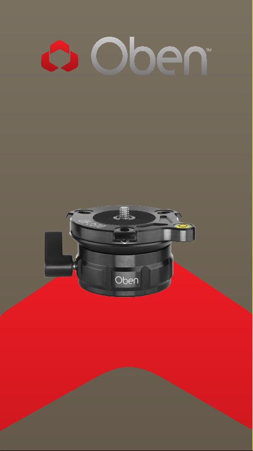
LH-2510
Leveling Base Head
You’re on steady ground
1
™
Page 2

INTRODUCTION
Thank You for choosing Oben!
The Oben LH-2510 is a du ra ble leveli ng base h ead
that is a s uperb sol uti on for level in g a ca mera or
cam corder independently of the tripod . It provides
smooth and acc urate leve li ng of a tripod h ead up to
ten degr ees i n any direction.
This le veli ng ba se head i s desig ned f or use with
tripod s th at don’ t have bu ilt-in leve ls. The int egrated
bubble lev el a ll ows for precise l eveling o f the
cam era, a nd t he fluid m ot ion o f the adjustable
base ens ur es t hat the c am era won’t slip when
ret ighten in g. He x scr ew s th at le t you tighten the
cam era to th e base as su re a se cu re atta ch ment.
The LH-2510 com es with a 3 /8″-16 bottom soc ket
for easy t ripod attachment, a nd a 1 /4″-20 top
stud for camer a attac hm ent . Addit ion al bus hi ngs
are included to make the bo ttom soc ket an d top
stud compat ib le w ith m ost tripod s, camera s, a nd
camcorders.
When the terrai n or la ck of time pr event a dju sting
each leg of a tr ipod , the LH-251 0 al lows for precise
angle adjustm ent a nd a secure lo ck down once you
hav e set t he l evel.
2
Page 3

TABLE OF CONTENTS
Key Features 4
Specifications 5
Operation 6
Mount Base to Tripod 5
Mount Camera to Base 6
Leveling the Camera 6
Warnings 7
3
Page 4

KEY FEATURES
D
F
A
B
C
D
E
A
1/4 ″-20 threaded mounting post
B
Fluid head (10° adjustment)
C
Rubber mounting pad
D
Tightening screws
E J
Bubble level
F K
Ratchet-style tightening screw
H
G
4
G
Rubber base pad
H
3/8″-16 treaded mounting
socket
I
1/4 ″-3/8″ bushing
3/8″-1/4 ″ bushing
Allen wrench
I
J
K
Page 5

OPERATION
1. Mount Head to Tripod
Screw the le veling ba se head i nto
the t ripod un ti l it is t ight.
Note: If the tr ipo d ha s a 1/4″-2 0
threa ded p ost , first s crew th e 3/8″
– 1/4″ bu sh ing int o th e bot tom
socket a nd t ighten w ith a flat h ead
screwd river. T hen scr ew the ba se
head into th e tr ipod.
2. Mount Camera to Base
Once the base hea d ha s bee n
securely at tached to th e tr ipod,
att ach the cam era wit h the
following steps:
1.Screw the ca mera into th e
threa ded p ost o f th e base until it
is ti ght .
Note: If the ca mera has a 3/ 8″-16
threa ded s ock et , scr ew t he 1 /4″
– 3/8 ″ bushing onto the t hread ed
post of th e base. T hen scr ew the
cam era onto the post u ntil it is
securely tightened.
2.S ecure the c am era by ti ghtening
the t hree screw s ar ou nd t he ba se
platfo rm w ith the Al len wrenc h.
Note: do not ove rt igh ten t he
screws . Doi ng so can cause
damag e to the ca mera.
5
Page 6

OPERATION
3. Leveling the Camera
1. T urn th e locki ng knob
cou ntercl ockwise to loosen t he
leveling base.
2. Lo oking a t the bubble lev el,
adjust t he leve l of the ba se unti l
the b ubble r ests in t he cente r of
the c ircle .
3. Tur n the locki ng knob
clockwise to t ighten and secure
the l eveli ng base .
Note: If it is di cult t o operate the
locki ng knob due to t he prox imity
of th e camer a, utilize th e ratchet
fu nction of th e locki ng knob:
• Pu ll the k nob out aw ay from
the b ase head, a nd tur n it to a
position whe re you ca n operat e
it without co ntacting the
camera.
Specifications
Bottom diameter 2.5″ (6.3 cm)
Platform diameter 2.75″ (7.0 cm)
Height 2.0″ (5.1 cm)
Weight 11.0 oz. (312 g)
Maximum load 25 lb. (11.3 kg)
Adjustment range 10° any direction
6
Page 7

Warni ngs:
!
• Please read and follow these instructions,
and keep this manual in a safe place.
• Do not attempt to attach the base head to a
tripod with the camera attached.
• Remove the camera from the head during
setup or transport.
• Do not exceed the head’s maximum load
capacity of 25 lbs. (11. 3 kg).
• Ensure that all appropriate locks are
engaged when necessary.
• Do not operate in salt water. Dry the head if
it becomes wet.
• Avoid long-term exposure to sunlight (to
prevent damage to your camera).
• Keep out of reach of children.
OPERATION
Visit our website at ObenSupports.com
for more Oben products.
7
Page 8

© Copyright 2014 The Gradus Group
All other trademarks are the property of their respective owners
www.obensupports.com
8
GG1
 Loading...