

Page 1
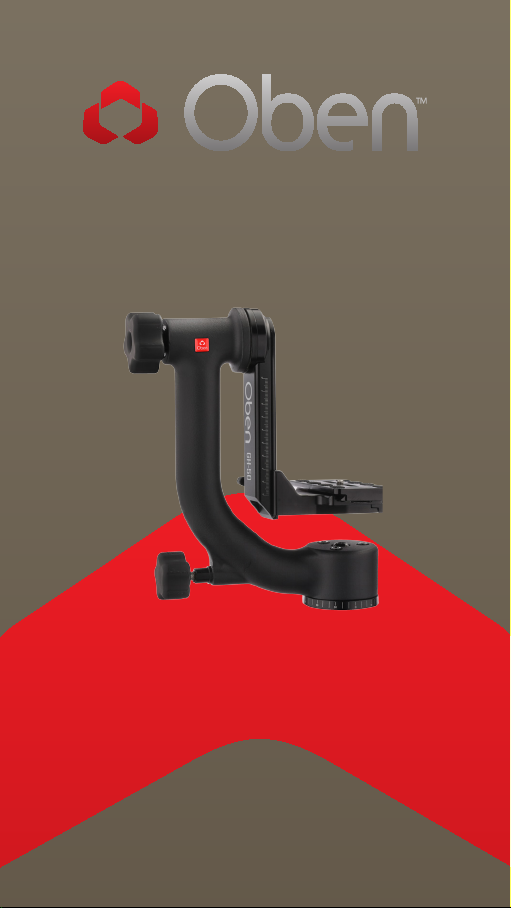
GH-50
Gimbal Head
You’re on steady ground
1
™
Page 2

INTRODUCTION
Thank You for choosing Oben!
The Oben GH-5 0 is a g im ba l-t yp e tr ipod head
design ed to b al an ce a lens a long its vertical
and hor izontal a xes. Id ea l for w ildlife or sport s
photography, medium or large telephoto lenses
can b e ti lted or sw iveled eort lessly and rem ai n
securely i n place once posit ioned . Th is gim bal
head is desig ned to ensure th at phot ographer s ca n
qu ickly a ch ieve the preci se position to captu re t he
desired subject.
Eng in eered w ith a str ong and dur ab le aluminum
main cur ved ar m, t he GH-50 suppor ts up t o 50
pou nds, yet ba la nces th e load so t hat eve n a la rge
len s fee ls weightless . Designed w ith secur ity of th e
len s in m in d, t he G H-50 featu res secure grooves th at
con nec t th e sw ingi ng a rm a nd q uick-relea se pl ate
platfo rm . The adjust ab le plat for m is desig ned with a
saf et y pin ass ur ing that th e len s will not sl ip o.
An A rca-type qu ick-releas e plate with t wo 1/4″-20
screws a nd a 3/8″ -1/4 ″ bushing is include d for e asy
att achment to mos t len s collars. The GH-50 m ou nts
to most tr ipods with a 3/8″ threaded stud.
Pho tog raphe rs using heavy len ses w ill ben efit fro m
the f reedom to mov e th e lens alon g with the solid
bal an ce a nd stabilit y o ere d by t he GH-50 .
2
Page 3

TABLE OF CONTENTS
Key Features
Mount Gimbal to Tripod
Attach Plate Platform to Gimbal
Attach QR Plate to Lens
Mount Lens
Balance Camera
Pro Tips
Specifications
4-5
6
7
8
9
10-12
13
14
Warnings
15
3
Page 4
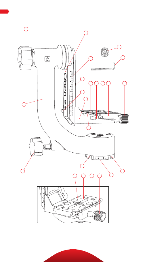
KEY FEATURES
A
D
M
B
P
C
L
G
J
H
E
F
J
R
I
H
J
K
Q
I
K
N
O
4
Page 5

A
Tension control/Swinging arm lock
B
Swinging arm
C
Swinging arm scale marks
D
Main curved arm
E
Platform adjustment knob
F
Plate platform
G
Attachment grooves
H
1/4″-20 mounting screws (2)
I
Arca-type quick-release (QR) plate
J
Quick-release plate scale marks
K
Plate release lock
L
Secure slot
M
Panning lock
N
Panning base
O
3/8″ tripod mounting socket
P
1/4″-20 to 3/8″-16 bushing (1)
Q
Allen key
R
Panning scale marks
KEY FEATURES
5
Page 6
OPERATION
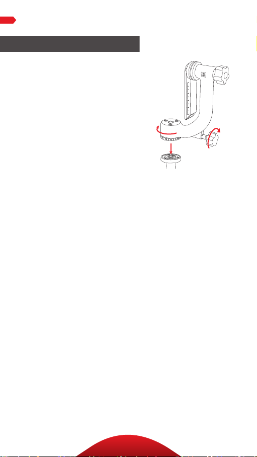
Mount Gimbal to Tripod
1. Tight en the pa nnin g lock until it
is secure.
2. A lign the mo unting soc ket of th e
pan ning base w ith the mou nting
post of th e tripod . Be careful to h old
the G H-50 strai ght over t he stud.
3. Screw t he head o nto the t ripod by
turn ing it clock wise on to the pos t
unt il it’s seated tightly against the
tripod plat form. Ma ke sure the re
are no gaps between the ba se and
the t ripod .
Important: If your tripod ha s set
screws o n the platform , tighten th em
to sec ure the GH-50 to t he tripod.
6
Page 7
OPERATION
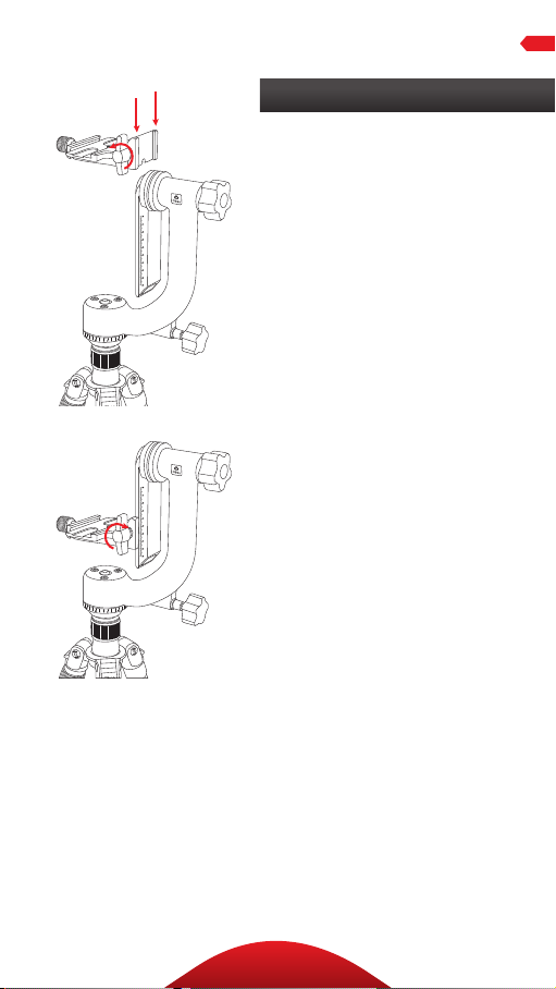
Attach Plate Platform to Gimbal
To at tach th e plate pl atfor m to the
swi nging ar m, do th e followi ng:
1. Al ign the s lot of th e platform w ith
the g roove s of the sw ingi ng arm ,
and sli de the pl atfor m down onto
the s wing ing arm until it rests on
the s top plate at the bo ttom of the
arm.
2. Ti ghten th e platform a djustmen t
knob un til the pla te platf orm is
securely locked onto th e swinging
arm.
7
Page 8

OPERATION
Attaching QR plate to Lens
The Arca-ty pe quick-release
plate ha s two 1/4″-2 0 mount ing
screws t hat att ach to most le ns
col lars. A 3/8 ″-20 bu shing is
included i n case th e lens col lar
has bot h 1/4″ and 3/8″ sockets.
Tighten the s crews of the qu ickrelease plate to the l ens col lar by
usi ng the A llen ke y (included) , a
coin, or the att ached D-ri ng.
Warning: Alw ays hold the
camera and lens while following
the a ttach ing an d balanci ng
instr uctions . Letting go of a n
un balanced camera can cau se it
to quic kly tilt an d cause damage
to your camera setup.
8
Page 9

OPERATION
Mount Lens
To at tach th e lens to t he GH-50, do
the following:
1. Tighten the swing ing ar m lock
and the platfo rm adjustment
knob ma king s ure th at both are
secured.
2. Loosen the plate re lease lo ck
completely.
3. Su pporting the len s with one
hand, pla ce the quick-relea se
plate wi th the le ns atta ched into
the g roove s of the plate plat form
and securely tight en the pl ate
release loc k. Mak e sure t he quickrelease plate is seated properly in
the p late platf orm and i s secur ely
tightened.
4. At t his poi nt you can slo wly ease
the c amera a nd lens to a resti ng
position an d let go. You r setup
can s afely rest i n a tilted position
wit hout bei ng held whi le you
prepare to balance it .
9
Page 10

OPERATION
Balancing Camera
First , perfo rm a prel imin ary ba lance of th e camer a
and len s by foll owing t hese steps:
1. W hile support ing the len s with on e hand , loosen t he
platfo rm adju stment knob wi th your oth er hand,
and mov e the pla tform up or down to al ign the
appr oxim ate vertic al center of t he lens w ith the a xis
of th e tension contr ol knob. (A)
2. Reti ghten th e platform a djustmen t knob.
3. Whi le stil l supporting the l ens wit h one hand,
loos en the pl ate rele ase lock . Move the q uickrelease plate so t hat the swing ing ar m is even w ith
the a pproximate m iddle o f the camer a and len s. (B)
4.Retighten all loc ks.
(A)
(B)
10
Page 11

OPERATION
Balancing Camera
Next, fi ne-tu ne the ba lance by do ing the f ollow ing:
5. S lightl y loosen t he swi nging a rm loc k to test th e bala nce.
6. Ti lt the le ns up at a 45° angle, a nd then dow n at a 45° angle.
If, in bo th cases, the lens want s to retu rn to a center posit ion,
the h eight of t he plate p latform needs to be adju sted.
a. Adjust the h eight up or d own. With o ne hand suppor t
the l ens and wit h the other h and, l oosen th e platform
adjust ment kn ob. Adjust t he height of the le ns up or down
and ret ighten t he platfor m adjustme nt knob . After eac h
adjust ment tes t the balance b y pointing t he lens u p and
down.
b. T he correct v ertic al balance is a chiev ed when the le ns
will rema in in pl ace when t ilted in one d irect ion. If the
len s moves back to the center when t ilted in the opposit e
direc tion, it wi ll need to b e adjust ed hori zontally (se e next
page).
11
Page 12

OPERATION
Balancing Camera
7. To adjust t he horizo ntal
balance:
a. T he direction t he lens t ilts
will determ ine whether to
adjust t he qui ck-relea se plate
forward or back.
• If the lens ti lts forward, the
quick-release plate needs
to be moved back .
• If the lens tip s backward,
the quick-release plate
needs to be moved forward .
b. Holding t he lens in a
horizontal position, support the
len s with on e hand and sl ightly
loos en the pl ate rele ase lock
wit h the other h and.
c. Sl ide the q uick-rele ase
plate forward or ba ck in sma ll
incremen ts to find t he perf ect
horizontal bala nce. Retighten
it af ter each adjustme nt to see
if the le ns tilt s.
d. The correct horizontal
bal ance is ach ieved when t he
len s and camer a can be ti lted
at an y angle— up or down —and
will rema in in pl ace.
With these adjustm ents, t he lens
can b e moved eor tless ly, and
will stay pointed i n any position
wit hout loc king t he swingi ng
arm.
12
Page 13

OPERATION
Pro Tips
1. For each pa rticul ar camera setup,
mark th e vertica l positi on on the
sca le mark s of the sw ingi ng arm ,
and the hor izontal posit ion on the
sca le mark s along t he qui ckrelease plate using ma sking tape
or a gr ease pen cil. B y maki ng
the se mark s, bala ncing the
cam era and len s will be much
fas ter in th e futu re.
2. To m axim ize im age sha rpnes s,
suppor t the camer a with yo ur
right ha nd while re sting y our lef t
hand on t he fron t thir d of the lens.
3. Follow the ma nufacturer’s
sugges tions r egard ing image
sta bili zation m odes on the lens.
13
Page 14

SPECIFICATIONS
Base diameter 2.4″ (6.0 cm)
Width 9.25″ (23.5 cm)
Height 9.3″ (23.6 cm)
Weight 3.3 lb. (1.5 kg)
Maximum load 50 lb. (22.7 kg)
Base pan range 360°
14
Page 15

Warni ngs:
!
• Please read and follow these instructions,
and keep this manual in a safe place.
• Do not loosen or remove the three
hexagonal screws on the top side of the
panning base.
• Do not attempt to attach the base head to a
tripod with the camera attached.
• Remove the camera and lens from the head
during setup or transport.
• Do not exceed the head’s maximum load
capacity of 50 lbs. (22.7 kg).
• Ensure that all appropriate locks are
engaged when necessary.
• Keep out of reach of children.
WARNINGS
Visit our website at ObenSupports.com
for more Oben products.
15
Page 16

© Copyright 2015 The Gradus Group
All other trademarks are the property of their respective owners
www.obensupports.com
16
GG1
 Loading...