

Page 1

AC-2300 CC-2300/2400 Series
Tripod
You’re on steady ground
1
™
Page 2

IntroductIon
Thank You for choosing Oben!
Congra tu lations on your pu rchas e of this sturdy,
multi-featured Oben AC-2300/CC-2300/CC-2400
Ser ies t ripod . It wil l deliv er light weight, roc k-solid
suppor t for you r ca mera fo r yea rs to come .
Adjust in g th e tr ipod’s height is si mple: ju st open
the fl ip locks t o ex ten d or retrac t each telescopic
leg se pa rat ely. T he ce nte r col um n locking k nob
releases the ce nte r colum n in a s plit sec ond t o
sli de up o r down for further he ight adjust me nt. The
cent er co lumn is groov ed to p revent it fr om rotating
accidentally.
Eac h leg c an be positioned indep endently at 3
locki ng angles (24˚, 55˚, or 80˚), and a built-i n
bubble lev el helps keep the tripod a ligne d with the
hor izon — both essen tial when w ork in g on uneven
ter ra in . Ru bberi zed non-slip leg war mers (for
alu minu m model s on ly) on two of th e leg s protect
you r ha nds in ho t or co ld weat her.
Please read this entire manual before using the AC2300 CC-2300/2400 Series tripod.
Note: Images are for illustrative purposes only. Actual
product may vary.
2
Page 3

tABLE oF contEntS
Key Features 5
Leg Length Adjustment 6
Leg Angle Adjustment 6
Center Column Adjustment 7
Low-Angle Setup 7
Counterweight 9
Mounting the Head 9
Retractable Spiked Feet 10
Warnings 11
3
Page 4
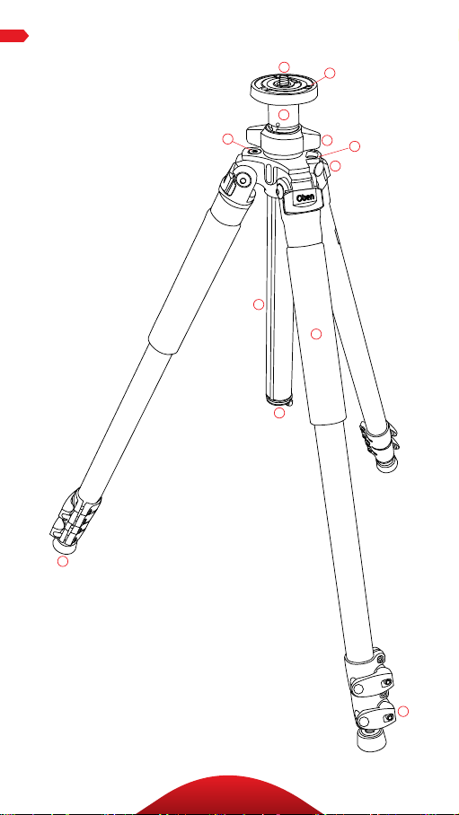
KEY FEAturES
I
D
B
G
C
A
J
E
L
K
H
F
4
Page 5

A
Center column locking knob
B
Short split-column
C
Grooved reversible center column
D
Head locking screws
E
Leg angle adjustment lock
F
Flip-style leg lock levers
G
Bubble level
H
All-terrain feet
I
Dual 3/8”-1/4”-20 head mounting screw
KEY FEAturES
J
Strap mount
K
Retractable and removable weight hook
L
Rubberized non-slip leg warmer
(for a lumi nu m mod els only)
5
Page 6

oPErAtIon
oPErAtIon
1. Leg Length Adjustment
A flip -loc k desig n al lows you
to quic kl y change the height of
each tel escopic tr ipod leg. T o
adjust t he h eight of a leg: p us h th e
lev er op en , positi on the leg at the
desired height , and pu sh t he leve r
closed to l ock the leg i n place.
Eac h flip lock includes a n Allen
screw that can be tightened or
loos ened using an A ll en w rench .
2. Leg Angle Adjustment
For stable s upport when shooting
on un even te rrai n, e ach leg of you r
tripod can be indiv idually s et at a
preset a ngl e of 24˚, 55˚ or 80˚.
To ch an ge a leg’s angle, pull t he
adjust ment lock ou tward an d set
the a ngle of th e leg. Pu sh t he lock
in to l ock t he leg at th at angle .
6
Page 7

oPErAtIonoPErAtIon
3. Center Column Adjustment
The sli di ng center colum n can
be used to adjust the he ight of
the c am era. F ul ly extending
the c ent er co lumn a ft er the le gs
hav e been fu ll y ex ten ded will
pla ce the ca me ra at t he h igh est
position pos sible w it h th is
tripod.
AdjuSt thE cEntEr coLumn
Tu rn t he center colum n locki ng
knob counterclock wi se, a dju st
the c ent er co lumn to the
desired height , and lock it i n
pla ce by t urni ng t he center
colu mn lock ing knob cl ock wise.
Ensure th at t he k nob is secure,
but do not o ver-tighten i t to
avoid da ma gi ng t he t ripod.
Note: Extending the center
column may leave the tripod less
stable .
4. Low-Angle Setup
There a re t wo ways t o adj ust
the t ripod for low-an gle s hots.
rEVErSE thE cEntEr coLumn
1. Remo ve t he bui lt-in w eight
hook from th e bottom of
the c olu mn by tur ni ng
it cou ntercl ock wise and
pulling it out o f th e colum n.
7
Page 8

oPErAtIon
4. Low-Angle Setup
2. Tur n th e cen ter c olu mn locki ng
knob counterclock wi se to
unloc k th e center colu mn .
Rem ove the center colu mn f rom
the t ripod.
3. Re verse t he center column a nd
inser t it up t he bott om of t he
tripod top pl ate .
4.Sli de t he co lumn i nto t he
desired pos iti on . Tu rn the
cent er co lumn lock in g kn ob
clockwise to lock at the desired
height. Repla ce the we ight hook
by screw ing it into th e cen ter
column.
SPLIt thE cEntEr coLumn
1. Remo ve t he weight hook fr om
the b ottom of the column by
turn in g it counterclo ck wi se and
pulling it out o f th e colum n.
2. Tur n th e cen ter c olu mn locki ng
knob counterclock wi se to
unloc k th e center colu mn .
Rem ove the center colu mn f rom
the t ripod.
3. Usi ng t he sma ll est i nclude d
Al len wrenc h, l oosen the Allen
screw located near t he top of t he
cent er co lumn . When t he A llen
screw is l oosene d, u ns crew th e
top par t of the center colum n
and rem ove it fr om the co lumn .
8
Page 9

oPErAtIon
4. Put the ma in column asid e.
Tighten the Al len screw with
the A llen wren ch so that th e
screw is fl ush wit h the surfa ce
of th e cen ter c olu mn. Insert the
short colu mn i nto the tripod .
Tighten the cent er co lumn
locki ng knob s ecurely.
5. Counterweight
When sh ooting un der wi ndy
condit ions or when u si ng a
teleph oto l ens, the st abil it y
of your camera i s cr iti ca l. T he
bui lt-in spring-loa ded hook at
the b ottom of the center colu mn
allow s yo u to hang a cou nte rweight fo r in creased st abil izati on ,
suc h as a (n ot incl uded) sa nd bag
or loaded equipmen t bag.
6. Mounting the Head
The tripod i nc lud es a mounti ng
screw with a 1 /4” screw o n one
end a nd a 3 /8” scr ew on the o th er,
allow ing you to mou nt eithe r size
tripod h ead. To s witch betwee n
the t wo sizes, re move the pl ate
fro m th e tr ipod by tur ni ng it
counter-clockwise.
Rem ove the screw, and inse rt t he
opposit e end back into th e plate.
Mou nt t he plate bac k onto the
tripod b y tu rning it clockw ise.
To mo unt a hea d, a li gn t he
bot tom of the tripod m ou nt w ith
the t ripod’s m ou nting s crew,
the n tw ist cloc kwise until fu ll y
secured. D o not ove r-tighten, a s
this may cause d am age.
9
Page 10

attaching head
oPErAtIon
6. Mounting the Head
The top plate on Oben tr ipods is
equ ipped with three set screws
which clamp against the base of
the t ripod head to e nsure eect ive
and secure locki ng of t he head to
the t ripod.
7. Retractable Spiked Feet*
A spi ke is built i nto each of the
tripod’s rubber feet . Th e ru bber
non- sk id feet a re for us e in doo rs or
on flat surfaces, wh il e th e spi kes
are for soft g round , grass , sand,
and on un ev en te rr ai n. T o ex tend
the s pi ke, rot ate t he r ubber pad at
the b ottom of the foot clock wi se
unt il t he s pike is fu lly expose d.
Tu rn t he foot countercl ock wise
to fully retract t he s pike into t he
ru bbe r foo t. F or CC-24 41, see note
below.
*Model CC-2441 features a
removable rubber cap with a spike
beneath it on each tripod leg. To
exchange a rubber foot for a spiked
foot, simply pull the rubber cap
o the leg, exposing the spike
underneath. When a rubber foot is
desired, replace the rubber cap over
the spike.
10
Page 11

Warni ngs:
• Do not exceed the tripod’s maximum load
!
capacity (see tag on tripod).
• Ensure that all appropriate locks are
engaged when necessary.
• Tripod should only be used in temperatures
between -22° and 140° Fahrenheit.
• Do not operate in salt water. Dry tripod o if
it becomes wet.
• Remove the camera from the tripod during
transport.
• Keep out of reach of children.
• To avoid injury, always support the top of
the center column with one hand while
adjusting height and locking the knob with
the other hand.
oPtIonAL AccESSorIES
• TS-110 Deluxe Padde d Neoprene Tripod St rap
wit h zip per ed po cket
• TS-10 0 Padded Neopren e Tr ipo d Strap
Visit our website at ObenSupports.com
for more Oben products.
WArnInGS
11
Page 12

© Copyright 2014 The Gradus Group
All other trademarks are the property of their respective owners
www.obensupports.com
12
 Loading...