

Page 1
BC Series
Dual Action Ballhead
You’re on steady ground
1
™
Page 2

IntroductIon
Thank You for choosing Oben!
This st ur dy Oben BC Se ries Du al-A ction ba llhead
provid es sm oot h, precise operation. T wo locks
provid e independent adjus tment a nd locking of
the b al l and pan ora mic base. A separ ate tension
thu mb screw in teg rated into th e main lo cking k nob
allow s you t o set a speci fic degr ee of f riction for
you r ca mer a set up. A s nap-in q uick-release plate is
includ ed, for eor tless mo untin g and dismount ing
of th e camera.
An i ntegrated bu bble level ensu res accurate
align ment of the ca mera with th e hor izon. T he
pan ora mic base of th e ballhead allows for f ul l 360 °
pan ning—idea l for s hoo ting pa nor am ic ph otos.
Please read through this entire manual before using the
BC series ballhead.
Note: Images are for illustrative purposes only. Actual
product may vary.
2
Page 3

tABLE oF contEntS
Key Features 4
Mount Ballhead To Tripod 6
Converting Mounting Thread 6
Main Locking Knob Operation 6
Mount Quick-Release Plate 7
Mount Camera 7
Tension Thumbscrew 8
Adjusting Friction 8
Panoramic Base 10
Warnings 11
3
Page 4
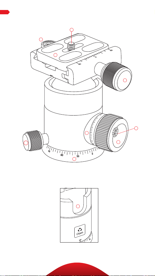
KEY FEAturES
C
B
A
D
F
E
I
J
H
G
4
Page 5

A
Quick-Release Plate
B
Bubble Level
C
1/4”-20 UNC Mounting Screw
D
Quick-Release Knob
E
Pan Knob
F
Tension Guide Scale
G
Main Locking Knob
KEY FEAturES
H
Tension Thumbscrew
I
Panoramic Base With 360° Markings
J
90° Groove
5
Page 6

oPErAtIon
1. Mount Ballhead To Tripod
To mo unt t he ballhe ad on t he
tripod , first ti ghte n al l of the
knobs on t he head . Then, being
car ef ul to prop erly a lign the
tripod stud a nd the ba ll head
hole to avoid damagi ng them ,
rotate the ba ll head clock wise
onto t he tripod, a nd tighten it
by hand.
2. Converting Mounting Thread
For tripods w ith a 1 /4″ th rea ded
mou nting stud: in sert th e
supplied red ucer bus hi ng into
the t hread ed mo unt ing hole of
the h ead to enabl e a pro per fit.
3. Main Locking Knob Operation
The mai n locki ng knob locks
and unlocks th e ballhead,
which allo ws yo u to ch ange th e
position of th e camera. W hen
cha nging c amera position
usi ng the ma in l ock ing knob,
alw ays k eep one ha nd on
the c am era . Tu rn the knob
cou nterclock wi se to u nlock the
head and cloc kw ise to loc k it.
Ensur e that th e main knob i s
fir mly t ightened bef ore l ettin g
go of t he ca mera.
6
Page 7

oPErAtIon
4. Mount Quick-Release Plate
Rem ove the q uick-release
plate fr om th e ballhead by
turning t he quick-release kn ob
cou nterclock wi se. T hi s loosens
the q uick-re lea se cl amp, al lowing
you to rem ove t he q uick-relea se
plate. Moun t the quick-release
plate to the th readed h ole o n the
base of your ca mera. Us e the
supplied hex key to tighten t he
screw. Th e pla te utilizes a 1/4″-20
screw th at will fit mos t cameras.
Warning: Some manufacturer’s
plates do not meet our specifications
and may not lock your equipment
securely in the Oben quick-release
clamp. Please test all camera and
lens plates made by manufacturers
other than Oben to ensure
compatibility.
5. Mount Camera
Af ter m ounti ng the qu ick-rele ase
plate to your camera , ensur e
that al l kn obs on the b al lhead
are tightened, e xce pt for the
qu ick-r elease k nob. Loosen t he
qu ick-r elease k nob by tu rning it
cou nterclock wi se un til it sto ps.
Mou nt the ca mer a to the ba ll hea d
by sl iding one edge of the quic krelease plate into th e ballhead
the n low er the ot her s ide u ntil th e
qu ick-r elease plate is lying fl at in
the q uick-re lea se cl amp. Tu rn the
qu ick-r elease k nob cloc kw ise to
lock the p late.
7
Page 8

oPErAtIon
5. Mount Camera (continued)
Warning: Always use one hand to secure the camera
while adjusting the ballhead, and ensure that the lock is
engaged before letting go of the camera .
6. Tension Thumbscrew
The tension t humbscre w is
integr ated into the m ai n loc ki ng
knob. It ’s used to co ntr ol the
amount of fr iction on th e ball in
order to mainta in stri ct co ntr ol
when positioning it.
7. Adjusting Friction
To adj ust the f ri cti on ac curate ly,
fol low t hese ste ps:
A. T ight en th e head an d mount
the l ightest c ombin ati on of
cam era a nd lens t hat you
will re gu la rly use. T ur n the
tension thu mbscrew (locat ed
on th e ma in locking k nob)
cou nterclock wise un til it sto ps.
B. Turn the m ai n loc ki ng knob
counterclockwise until you
reach th e des ired mi ni mum
deg ree of frict ion . You ca n set
the f ricti on so t hat t he ball
mov es freel y or so that it is
immobilized or anywh ere i nbet ween.
8
Page 9

oPErAtIon
C. Turn the t ens ion t humbscre w
clockwise unt il it s tops. You
hav e now s et yo ur m in imal
frict ion l im it for this pa rticu la r
cam era a nd lens comb ination.
The mai n locki ng knob w il l not
t ur n beyon d thi s mini mal f rict ion
limit.
If yo u want to moun t a heavie r camera and lens
com bination , you w ill need to repeat t hi s process ,
increa sing th e ten sio n on the ball by follow ing the
sam e ste ps with the ne w camera/ len s com binat ion .
Import ant: to lower you r mi ni ma l fr ict ion l im it,
turn the ma in lock ing kno b clockwis e unt il it stops,
turn the tension thum bscrew counterclockw ise
unt il it stop s, then t ur n the main locki ng k nob
cou nterclock wi se un til the b al l mov es freely eno ugh
for you to m ake adjust ments.
Warning! Do not force the main locking knob to turn
beyond its stopping point. This leads to “locking up”
or “freezing up” of the main locking knob—you will
be unable to move it. In this condition, the knob is
locked, but the head is loose. To correct this, increase
tension on the ball by rotating the main locking knob
clockwise until the desired degree of tension is achieved.
Release the friction by turning the tension thumbscrew
counterclockwise until it stops. Release tension on the
ball by rotating the main locking knob counterclockwise
until the ball is free.
9
Page 10

oPErAtIon
8. Panoramic Base
The base o f the bal lh ead c an
be independently rotated
360°. The base is controll ed by
loos ening t he pa n knob. T hi s is
the s ma llest k nob , at the base
of th e hea d. T wi st the kn ob
cou nterclock wi se to u nlock
the b ase , rot ate t he ba se to
the d esi red p osition, and lock
the b ase b y tu rn ing the k nob
clockwise. Degree marki ngs
on th e bas e of th e ballhead can
be used to ac curate ly set up
panoramic shots.
10
Page 11

Warnings:
• Do not exceed the ballhead’s maximum
!
load capacity (see packaging for details).
• Ensure that all appropriate locks are
engaged when necessary.
• Ballhead should only be used in
temperatures ranging between -22° and
140° F. Do not operate in saltwater. Dry
ballhead if it becomes wet.
• Remove the camera from the ballhead
during setup or transport.
• Keep out of reach of children .
Visit our website at ObenSupports.com
for more Oben products.
WArnInGS
11
Page 12

© Copyright 2014 The Gradus Group
All other trademarks are the property of their respective owners
www.obensupports.com
12
 Loading...