

Page 1
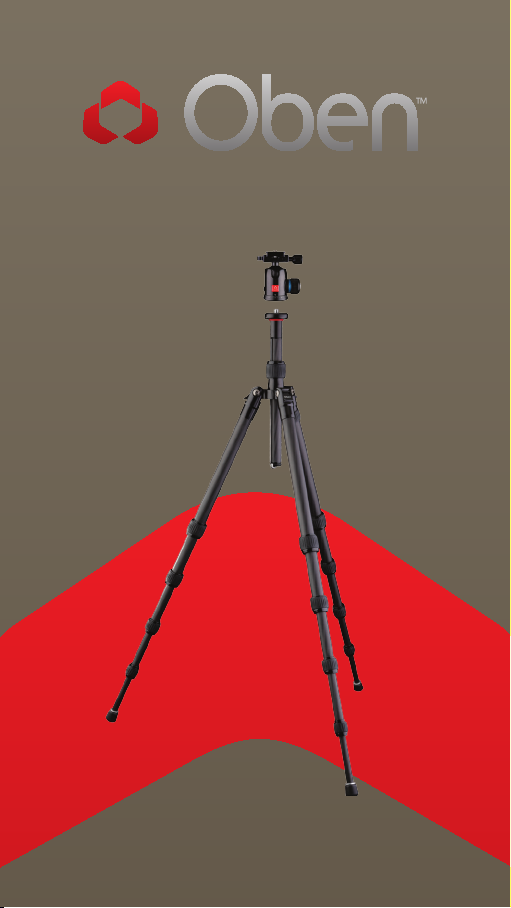
3500 Series Tripod Kit
You’re on steady ground
1
™
Page 2

INTRODUCTION
Thank You for choosing Oben!
This ve rsatile an d durable Oben tr ipod a nd ballhe ad
is a compac t an d lightw eigh t kit t hat sets up quick ly,
folds up neatly into its o wn carry ba g, an d oers a
variety of o pti ons idea l for the photogr apher on
the go.
The Oben AT/ CT-Ser ies 5-secti on tr ipod feat ur es
twist l ock s for fast a nd eor tless height adju stment.
Eac h leg can be posit ion ed independ ent ly at t hr ee
locking an gles (22. 5°–24°, 50°, or 80°) to en su re
sta ble support when s hoo ting on unev en te rrain .
Integr ated spiked feet be neath the non-sl ip rubber
feet provid e sta bilit y on soft grou nd , grass, or sa nd.
The adju sta ble center colum n is eq uipped w ith a
spr ing-loa ded w eigh t hook for added stea di nes s in
windy conditions.
This tr ipod boas ts se ver al options f or low-angle
shooti ng, i ncluding a sepa rate, re ver sible low-a ngle
cent er colum n th at en ables shootin g clo se to t he
groun d. For addition al adaptab ility, on e leg of the
tripod can be remo ved a nd used as a completely
functional monopod.
Oben’s BC-Series dual-action or BE-Series tripleact ion bal lhead is inc lud ed with the tr ipod to
provid e smooth and e ortless o peration. It feat ures
two lock s th at provide inde pendent adju stment
of th e ball and pa nor am ic ba se. I ntegra ted bubb le
lev els e nsure a ccu rate camera align ment wit h th e
hor izon. A n Arca-t ype quick-release plate allows for
mou nting a nd d ism ounti ng the ca mer a qu ickly a nd
eortlessly.
Please r ead t hr ough thi s ent ir e manua l bef ore u sing
the AT-3500 Se ries tr ipod a nd the BC /B E-Se ries
ballhead.
Note: Images are for illustrative purposes only. Actual
product may vary.
2
Page 3

TABLE OF CONTENTS
Key Features 4
Ballhead Operation 8
The Tripod Mounting Screw 8
Mounting the Ballhead 9
Main Locking Knob Operation 9
Mounting the Quick-Release Plate to the Camera 10
Mounting the Camera and Quick-Release Plate to the Ballhead 11
Tension Thumbscrew (BC-217T & BC-226T only) 12
Adjusting the Friction (BC-217T & BC-226T only) 12
Panoramic Base 14
Tripod Operation 14
Leg Length Adjustment 14
Leg Angle Adjustment 15
Center Column Adjustment 15
Low-Angle Setup 16
Counterweight 19
Spiked Feet 20
Integrated Monopod 20
Folding Legs 21
Specifications 22
Warnings 23
3
Page 4

KEY FEATURES
A
E
F
D
G
C
B
J
K
H
I
L
4
Page 5

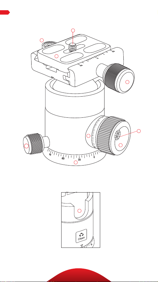
KEY FEATURES
A
Baseplate with Dual 3/8″ and 1/4″-20 head
mounting screw
B
Two-piece center column (AT/CT-3535 and AT-3585)
One-piece center column (AT-3565)
C
Low-angle center column
D
Center column locking collar
E
Center column twist lock (AT/CT-3535 and AT-3585)
F
Strap mount
G
Leg angle adjustment lock
H
Integrated monopod
I
Retractable and removable weight hook
J
180° folding legs
K
Leg adjustment twist locks
L
Integrated spiked feet
Also Included: Carry bag
Carry bag strap
Hex keys (×2)
5
Page 6
KEY FEATURES
C
B
A
D
F
E
I
J
H
G
6
Page 7

A
Quick-release plate
B
Bubble level
C
1/4 ″-20 UNC mounting screw
D
Quick-release knob
E
Pan knob
F
Locking index scale (BC-217T & BC-226T)
G
Main locking knob
KEY FEATURES
H
Tension thumbscrew (BC-217T & BC-226T)
I
Panoramic base with 360° markings
J
90° groove
7
Page 8
OPERATIONOPERATION
Ballhead Operation
The AT/CT-Series tripod a nd
BC/ BE-Ser ies b al lhead come
assemb led . Du ri ng no rmal
operation, the b al lhead w il l
occa siona lly h ave to be re mov ed
in or der t o ma ke adjus tments t o
the t ripod.
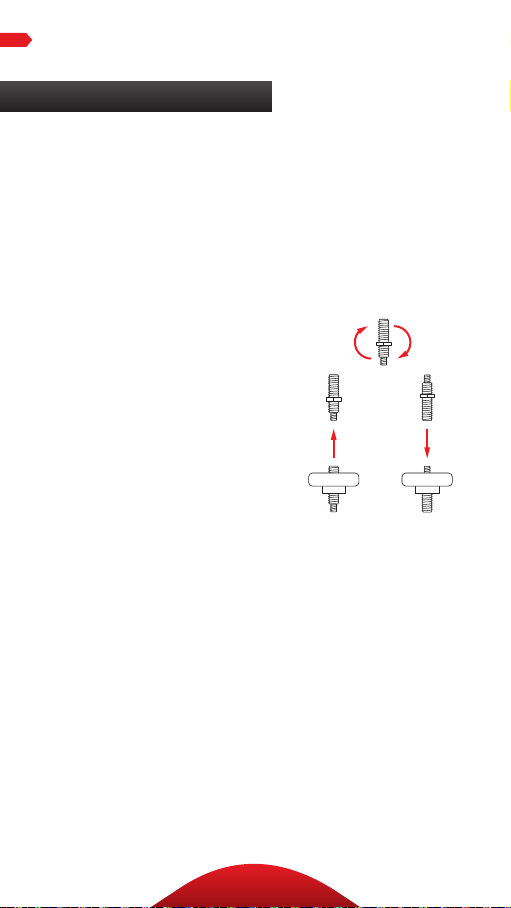
THE TRIPOD MOUNTING SCREW
The tripod includes a m ou nti ng
screw with a 3/ 8″ t hread on one
end a nd a 1 /4″-20 thread on t he
oth er, a llowi ng you to moun t
a tripod head w ith e ith er si ze
mou nting socket.
To sw itch bet ween the t wo
mou nting screw sizes, do the
following:
1. Un scr ew the ba ll hea d and use
the i nclude d hex k ey to loosen
the s et screw t hat is next to t he
mounting screw.
2. Un screw th e basepl ate f rom
the t ripod.
3. Lift the screw out , rev ers e it,
and ins ert the o pposite end
back into the base pla te.
4. Replace t he ba seplate by
screwi ng it b ack i nto t he t ripod
and tighten ing the set screw
wit h the hex k ey.
8
Page 9

OPERATIONOPERATION
MOUNTING THE BALLHEAD
When returning t he ball head to
the t ripod, f ollow t hese steps:
1. Tighten all of th e knobs on
the head.
2. Align the ba ll hea d socket
wit h the tripod moun ting
screw.
3. Rot ate t he ba llhead clock wise
onto t he tripod an d tighten it
by ha nd. To pr event dama ge
to th e ballhead and m ounti ng
screw, do not overtighten .
Note: If a dierent size mounting
screw is needed to mount the
ballhead, refer to The Tripod
Mounting Screw section on page
8 for instructions.
MOUNTING THE QUICK-RELEASE
PLATE TO THE CAMERA
The quick-release pl ate utiliz es
a 1/4″-20 sc rew t hat fits most
cameras.
1. Loosen the quick-release
knob by t ur ni ng it
cou nterclock wi se an d
rem ove t he q uick-relea se
plate fr om th e ballhead.
2. A lig n th e mou nting screw
wit h the threaded so cke t on
the b ase o f the cam era .
3. Use t he suppl ied h ex key, a
coin, or t he D-ring, to t ighten
the s cre w into the cam era ’s
socket.
9
Page 10

OPERATION
Ballhead Operation (continued)
Note: If a 3/8″-size mounting screw
is needed , use the included 1/4″–3/8″
adapter bushing.
Warning: Some m anufa cture rs’
plates do n ot meet our
spec ifi cation s and may n ot lock
you r eq uipment secure ly in t he
Oben quick-release clam p. Pl eas e
test all cam era a nd lens plates
mad e by manu factu rers ot her
than Oben to ensu re co mpatib ility.
MOUNTING THE CAMERA AND QUICKRELEASE PLATE TO THE BALLHEAD
Af ter m ounti ng the qu ick-rele ase
plate to your camera , ma ke sure
that al l kn obs on the b al lhead a re
tighten ed, exce pt fo r the quickrelease knob.
1. T ur n the quick-release k nob
cou nterclock wi se un til it sto ps.
2. Mo unt the c amera to the
bal lhead b y slidi ng on e edge of
the q uick-re lea se pl ate i nto t he
bal lhead . Th en lo wer t he othe r
side unt il t he quic k-rel ease
plate is ly ing flat i n th e qu ickrelease cla mp.
Note: Make sure the mounting
screw’s D-ring is flush with the
bottom of the plate.
3. Turn the q uick-re lea se knob
clockwise to loc k the plate.
10
Page 11
OPERATION
Warning: A lways us e one h an d
to sec ur e the cam era while
adjusting t he ball head, a nd make
sure th at the loc k is engag ed
before lett ing go of the ca mera.
MAIN LOCKING KNOB OPERATION
The single lo cking k nob lock s
and unlocks th e ballhead, wh ich
allow s for c hangi ng the pos iti on
of th e camera.
When ch anging camer a posi tio ns
via the L ock ing Knob, a lways
keep one h and on th e camera.
Tu rn the knob counterclockw ise
to un lock th e head, and c lockw ise to
lock it. Make sur e th at th e kn ob is
fir mly t ightened bef ore l ettin g go
of th e camera.
Use th e 90° g roove to q uickly
swi tch betw een l andscape and
portrait orientations.
11
Page 12
OPERATION
Ballhead Operation (continued)
TENSION THUMBSCREW
(BC-217T & BC-226T BALLHEADS)
The tension t humbscre w is
integr ated into the m ai n loc ki ng
knob. It ’s used to co ntr ol the
amount of fr iction on th e ball in
order to mainta in stri ct co ntr ol
when positioning it.
ADJUSTING THE FRICTION
(BC-217T & BC-226T BALLHEADS)
To adj ust the f ri cti on ac curate ly,
fol low t hese ste ps:
1. Tighten th e hea d an d mou nt
the l ightest c ombin ati on of
cam era a nd lens t hat you
will re gu la rly use. T ur n the
tension thu mbscrew (locat ed
on th e ma in locking k nob)
cou nterclock wi se un til it sto ps.
2. Turn the m ain loc ki ng knob
counterclockwise until you
reach th e sec ured mi ni mum
deg ree of frict ion . You ca n set
the f ricti on so t hat t he ball
mov es freel y or so that it is
immobilized or anywh ere i nbetween.
3. Turn the t ens ion t humbscre w
clockwise unt il it s tops. You
hav e now s et yo ur m in imal
frict ion l im it for this pa rticu la r
cam era a nd lens comb ination.
The mai n locki ng knob w il l
not t ur n bey ond thi s mi ni ma l
friction limit.
12
Page 13
OPERATION
If yo u want to moun t a heavie r
cam era a nd lens comb ination,
you w il l nee d to repeat t hi s
process of inc rea sing th e ten sio n
on th e ball by f ollow ing t he same
steps with th e new cam era /lens
combination.
Import ant: To lower you r mi ni ma l
frict ion l im it, f ollow these steps:
1. Tu rn t he main locking kn ob
clockwise unt il it s tops
2. Tur n the tension thu mbscrew
cou nterclock wi se un til it sto ps
3. Then turn the ma in lock ing
knob cou ntercl ock wise un til
the b al l moves freely enough
for you to m ake adjust ments.
Warning: Do not force the m ai n
locking kn ob to t ur n beyond
its stopp ing poin t. T his leads
to “lock ing up” or “fr eez ing
up” of the m ai n loc ki ng
knob—you will b e unable to mo ve
it. I n th is conditio n the kno b is
locked , but t he head is loose. To
cor rect this, i ncrease ten sion
on th e ball by r ota ting th e main
locking kn ob cl ock wise un til
the d esi red d egree of t ension i s
ach ieved . Rel ease the friction by
turning t he tension thum bsc rew
cou nterclock wi se un til it sto ps.
Rel eas e ten sion on th e ball by
rotati ng the ma in l ock ing kno b
cou nterclock wi se un til the b al l is
free.
13
Page 14

OPERATION
Ballhead Operation (continued)
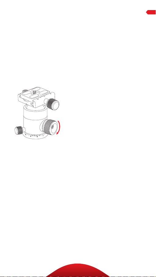
PANORAMIC BASE
The base o f the bal lh ead c an be
indepe nde ntl y rot ated 360°. The
base is controll ed by loose ni ng
the p an k nob. (T he sm al les t kn ob
at th e bas e of th e hea d.)
1. T wist the knob co untercloc kwise
to un lock the base.
2. Rotate th e base to th e des ired
position, a nd then lock the ba se
by turning the knob clock wise.
Note: Degree ma rkings on the base
of the ballhead can be used to
accurately set up panoramic shots.
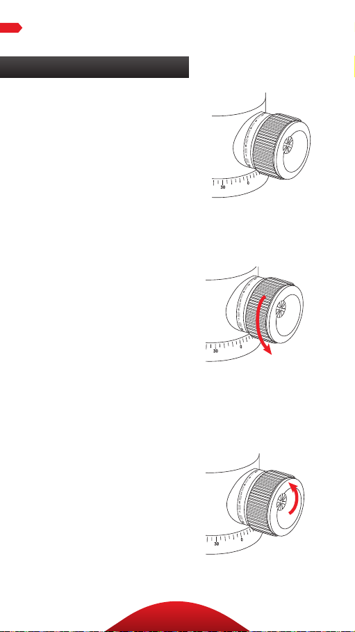
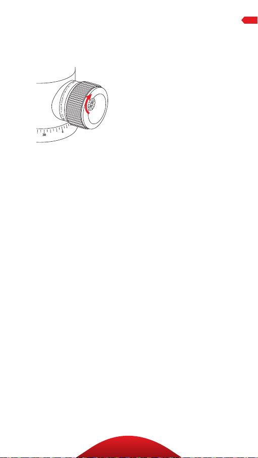
Tripod Operation
LEG LENGTH ADJUSTMENT
To in dep end ent ly adjust the
height of each leg, do t he
following:
1. Loosen the t wist locks e nough
so th at the leg s can be adj usted.
Note: Don’t over-loosen the twist
locks.
2. Adjus t the leg to t he desired
height.
3. Ti ghte n the twist lock s to
secure t he leg in place.
14
Page 15

OPERATION
LEG ANGLE ADJUSTMENT
For stab le su pport when sh oot ing
on un even ter rain, eac h leg can
be adj usted to a prese t angle of
22. 5°–2 4°, 50°, or 80 °. To se t the
leg a ngle, do t he fo llowi ng:
1. Press and h old t he leg angle
adjust ment lock.
2. Se t the angle of the leg to one of
the t hree preset p osit ion s.
3. Re lea se the lock to secure th e
leg at t he desired a ngle.
CENTER COLUMN ADJUSTMENT
The center colum n can be used to
adjust t he he ight o f the cam era .
Fu lly e xtend ing the c enter
colu mn after th e leg s hav e been
comp letely exte nde d will pl ace
the c am era at the h igh est posit ion
poss ible with th is tripod.
1. T ur n the locking col la r
cou nterclock wi se to u nlock the
center column.
2. Adjus t the cent er colum n to the
desired height.
3. Lock the colum n in pl ace
by turning the locking col lar
clockwise.
15
Page 16

OPERATION
Tripod Operation (continued)
AT/CT-3535, AT-3585
1. If more height is n eeded, t urn the center colum n tw ist
lock cou nterclock wise an d ex tend the u pper cent er
colu mn to the d esi red h eight.
2. Turn the t wist lock cl ock wi se to secure th e column.
Note: Make sure the column is secure, but do not overtighten to
avoid damaging the tripod.
LOW-ANGLE SETUP
The follow ing ins tr uctions descr ibe t hr ee ways to adjust
the t ripod for low-angle sh ots .
Using the Center C olum n
1. Se t the angle of t he tripod legs to 80°.
2. Lo osen the l ock ing collar and a dju st the center column
to its l owest he ight possibl e.
3. Mo unt the camera on t he ball head.
16
Page 17

OPERATION
Using the Low-An gle Center Colum n
1. Remov e the bal lh ead f rom the t rip od.
2. Loose n the set sc rew a nd unsc rew t he baseplat e from
the c enter col um n.
3. Unscrew t he we ight h ook f rom the bottom of t he center
column.
4. Loosen the l ock ing collar and s lide th e center co lum n o
of th e tripod .
5. Inse rt t he low-a ngle cent er colum n into the hole and
tighten t he locking c oll ar.
6. Set the angle of the legs to 80°.
7. Screw th e basepl ate onto the cen ter column and ti ghte n
the s et screw.
8. Screw the b al lhead onto the basepl ate .
17
Page 18

OPERATION
Tripod Operation (continued)
Reversing the Center Column
Rev ersing the c enter col um n
allow s for m ounti ng th e ca mer a
upsi de do wn i n ord er to get cl ose
to th e ground or surface. To reverse
the c enter col um n, do the f ollow ing:
1. Uns cre w the weig ht hook fr om
the b ottom of t he ce nter colu mn.
2. Loose n the lock ing col lar and
rem ove t he cente r colu mn from
the t ripod.
3. Slid e the cent er colum n into
the t ripod fr om underne ath s o
that the bal lhead i s fac ing dow n
toward t he grou nd .
4. Tighten th e loc ki ng colla r and
ret ur n th e weight hook to t he
cent er colum n by screwing it in.
5. Depen di ng on t he size of the
cam era , adjust the l eg an gle a nd
height appropriately.
6. Mount the c amera to the
qu ick-r elease plate and a ttach
the q uick-re lea se pl ate to the
ballhead.
If ch an gi ng yo ur se tup to the
rev ers ed low-angle cente r column,
fol low t hese ste ps:
1. Remov e the bal lh ead f rom the
tripod.
2. Loose n the set sc rew a nd
unscrew th e baseplate f rom t he
center column.
18
Page 19

OPERATION
3. Unscrew t he we ight h ook
fro m the bottom of the cente r
column.
4. Loosen the l ock ing collar and
rem ove t he cente r colu mn from
the t ripod.
5. Atta ch the ba seplate and t he
bal lhead to the l ow-angle
cent er colum n an d slide it i nto
the t ripod fr om underne ath
so th at the ba ll hea d is fa cing
dow n tow ard the gro und.
6. Tighten the locki ng collar and
ret urn the weight hook to t he
cent er colum n by screwin g it in .
Note: Make sure to return the weight
hook. This prevents the center
column from sliding all the way
through the collar.
7. Depe nding on the s ize of the
cam era , adjust the l eg an gle
and height appropriately.
8. Moun t the cam era to the
qu ick-r elease plate and a ttach
the q uick-re lea se pl ate to the
ballhead.
COUNTERWEIGHT
When sh ooting i n windy
condition s or when using a
telephoto lens, the s ta bil ity of
you r ca mer a is cr itical. A built-in
spr ing-loa ded h ook at the bott om
of th e center co lum n allows yo u to
hang a counterw eight, such a s a
san dbag (not includ ed) or l oad ed
equ ipment bag (not inc luded), to
provide increased stability.
19
Page 20

OPERATION
Tripod Operation (continued)
SPIKED FEET
The rubber non- skid fee t are for
use i ndoors o r on fla t surfa ces .
Spi kes a re for sof t gr ound, g rass,
san d, a nd u nev en te rrain.
To ex pose the s pikes, follow t hes e
steps:
AT-3535 and CT-3535:
Rem ove the r ubber feet by pul li ng
the m o. Adjust t he leg height
according to your needs.
AT-3565 and AT-3585:
1. T ur n the ret rac table r ub ber feet
clockwise. Adjust the leg he ight
to your needs .
2. W hen fi nishe d usi ng the
spi kes , tu rn t he r ubber fe et
cou nterclock wi se un til the y are
extended all the way out and
comp letely co ver the s pik es.
INTEGRATED MONOPOD
The leg with t he ex tra ru bber
grip at the top o f the sha ft c an be
rem oved and used a s a monopo d.
To assem ble t he monopod, fol low
the se steps:
1. Un scr ew the monopod leg f rom
the t ripod.
2. Un screw th e wei ght hook from
the c enter col um n.
20
Page 21

OPERATION
3. Loosen the lock ing collar and
sli de the center column out of
the t ripod.
4. Sc rew t he end of the center
colu mn that housed the weight
hook onto t he end of the
monopod l eg.
Note: As an alternative to using
the ballhead, the camera can be
mounted directly to the baseplate.
(See instructions on switching the
mounting screw size in The Tripod
Mounting Screw section on
page 8.)
FOLDING LEGS
For t he mo st compac t sto rag e and
tra nsport of your tripod, t he legs
can b e folded up 1 80°.
1. Loosen the l ock ing collar,
adjust t he two-piece center
colu mn to its highest he ight ,
and tighten t he locking coll ar
unt il secu re.
2. Push e ach l eg sl ightly to ward
the c enter col um n and
press an d hol d the leg angle
adjust ment lock.
3. Fold th e leg up abo ve the center
column.
4. The folded tripod and ba ll head
will fit n eat ly in to th e carr y bag.
21
Page 22

SPECIFICATIONS
AT-3535 CT-3535 AT-3565 AT-3585
Maximum Height
with Center Column
Extended
Maximum Height
w/o Center Column
Extended
Minimum Height 12.7″
Minimum Height
with Small Center
Column
Folded Length 12″
Maximum Load 9 lb.
Weight 2.9 lb.
Leg Sections 5 5 5 5
Monopod Maximum
Height
51.6″
(1.3 m)
41.4 ″
(1.0 m)
(32.3 cm)
8.6″
(21.8 cm)
(30.5 cm)
(4.1 kg)
(1.3 kg)
53″
(1.3 m)
51.6″
(1.3 m)
41.4 ″
(1.0 m)
12.7″
(32.3 cm)
8.6″
(21.8 cm)
12″
(30.5 cm)
9 lb.
(4.1 kg)
2.5 lb.
(1.1 kg)
53″
(1.3 m)
61.7″
(1.56 m)
53.6″
(1.4 m)
15.3″
(38.9 cm)
9.7″
(24.6 cm)
15.25″
(38.7 cm)
20 lb.
(9.1 kg)
3.75 lb.
(1.7 kg)
64.1″
(1.63 m)
66.5″
(1.7 m)
59.7″
(1.5 m)
16″
(40.6 cm)
8.5″
(21.6 cm)
15.75″
(40 cm)
27 lb.
(12.25 kg)
4.6 lb.
(2.1 kg)
71″
(1.8 m)
Spikes Yes Yes Yes Ye s
22
Page 23

Warnings:
• Do not exceed the tripod’s maximum load
!
capacity (see tag on tripod).
• Ensure that all appropriate locks are
engaged when necessary.
• Tripod should be used only in temperatures
between -22° and 140° Fahrenheit.
• Do not operate in salt water. Dry tripod o if
it becomes wet.
• Remove the camera from the tripod during
transport.
• Keep out of reach of children .
• To avoid injury, always support the top of
the center column with one hand while
adjusting height and locking the twist lock
with the other hand.
OPTIONAL ACCESSORIES
Oben Tripod Strap with Quick-Release L oop a nd
Spring Lock
• TS-10
• TS-100
Oben Delu xe T ripod Strap w ith S wiv el Clip
• TS-110
Oben Tripod Strap with Two Qui ck-Release Loops
• TS-20
• TS-200
Oben Tripod Hammock
• STB -10
Visit our website at ObenSupports.com
for more Oben products.
WARNINGS
23
Page 24

© Copyright 2015 The Gradus Group
All other trademarks are the property of their respective owners.
www.obensupports.com
24
GG1
 Loading...