

Page 1

AC-2300L/CC-2300L/2400L Series
Lateral Tripod
You’re on steady ground
1
™
Page 2

IntroductIon
Thank You for choosing Oben!
Congra tu lations on your pu rchas e of this sturdy,
multi-featured Oben AC-2300L/CC-2300L /
CC-2 400L Se ries later al t ripod . It will del iver
lightw eight, rock-sol id support for yo ur camera
for years to come . In a dd iti on to p roviding no rm al
ver ti ca l tr ipod suppor t for you r ca mera, the center
colu mn of this tripod ca n be pl aced in a h or izontal
position an d rotated from 90° up to 90° down from
the h or izontal . Th e ca mera ca n be placed at a ny
point in t his 180 ° ra nge. This is id ea l for c lose-up
macro photography, document photography, or any
photog rap hy requiri ng a ca mera positi on that ’s not
ava il ab le in the traditiona l tripod config urati on .
Adjust in g th e tr ipod’s height is si mple: ju st open
the fl ip locks t o ex ten d or retrac t each telescopic
leg se pa rat ely. T he ce nte r col um n locking k nob
releases the ce nte r colum n in a s plit sec ond t o
sli de up o r down for further he ight adjust me nt. The
cent er co lumn h as a square shape to p reven t it from
rotating accidentally.
Eac h leg c an be positioned indep endently at 3
locki ng angles (24˚, 55˚, or 80˚), and a built-i n
bubble lev el helps keep the tripod a ligne d with the
hor izon — both essen tial when w ork in g on uneven
ter ra in . Ru bberi zed non-slip leg war mers (for
alu minu m model s on ly) on two of th e leg s protect
you r ha nds in ho t or co ld weat her.
Please read this entire manual before using the Oben
AC-2300L/CC-2300L/CC-2400L Series tripod.
Note: Images are for illustrative purposes only. Actual
product may vary.
2
Page 3

tABLE oF contEntS
Key Features 5
Retractable Spiked Feet 6
Leg Length Adjustment 6
Leg Angle Adjustment 6
Center Column Adjustment 7
Low-Angle Setup 8
Mounting the Head 9
Warnings 10
Notes 11
3
Page 4
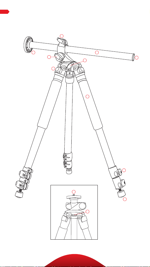
KEY FEAturES
callouts
180 °
A
F
C
G
J
E
D
L
K
B
H
I
4
Page 5

A
Center column locking knob
B
Center column release push-button
C
Center column angle locking knob
D
Center column rotating locking knob
E
Square shaped center column
F
Head locking screws
G
Leg angle adjustment lock
H
Flip-style leg lock levers
I
All-terrain feet
KEY FEAturES
J
Dual 3/8”-1/4”-20 head mounting screw
K
Strap mount
L
Rubberized non-slip leg warmer
(for a lumi nu m mod els only)
5
Page 6
oPErAtIon
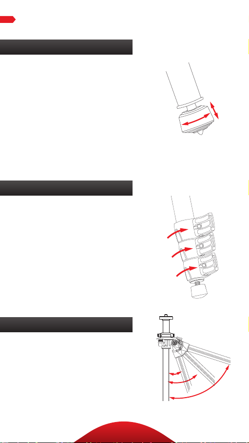
1. Retractable Spiked Feet
A spi ke is built i nto each of the
tripod’s rubber feet . Th e ru bber
non- sk id feet a re for us e in doo rs
or on flat su rfaces, wh il e the
spi kes are for soft g round , grass ,
san d, a nd unev en terrai n. To
extend the spi ke , rotate the
ru bbe r pad at th e bot tom of the
foot clockwise unti l th e spike
is ful ly ex posed. T urn the foo t
cou nte rclockw ise to re tract t he
spi ke i nto t he r ubber foot .
2. Leg Length Adjustment
A flip -loc k desig n al lows you
to quic kl y change the height of
each tel escopic tr ipod leg. T o
adjust t he h eight of a leg: p us h
the l ever op en, position the leg
at th e des ir ed height, a nd push
the l ever cl ose d to lock the le g
in pl ace. Ea ch fl ip lo ck i ncludes
an A ll en sc rew that ca n be
tightened or loosened using an
Allen wrench.
3. Leg Angle Adjustment
For stable s upport when
shooti ng on uneven t er rain ,
each leg of your tripod ca n be
indiv idually s et at a p res et a ngle
of 24˚, 55˚ o r 80˚.
6
Page 7

oPErAtIon
leg angle adj
To ch an ge a leg’s angle, pull t he
adjust ment lock ou tward an d set
the a ngle of th e leg. Pu sh t he lock
in to l ock t he leg at th at angle .
4. Center Column Adjustment
The sli di ng center colum n can
be used to adjust the he ight of
the c am era. F ul ly extending t he
cent er co lumn a ft er the legs h ave
been f ully exte nded wi ll place the
cam era at th e hi ghe st posit ion
poss ible with t hi s tr ipod. For lowangle sh ots or to u se ot he r camera
positions n ot av ai la ble using the
tra ditio na l tr ipod con figuration,
the c ent er co lumn can be p laced
horizontally.
AdJuSt thE cEntEr coLumn
Tu rn t he center colum n locki ng
knob counterclock wi se, a dju st
the c ent er co lumn to the desired
height, and loc k it in pla ce by
turn in g the center colu mn l ocking
knob clock wise. E ns ur e th at the
knob is secu re, but do n ot overtighten it to av oid d amag in g th e
tripod.
Note: Extending the center column
may leave the tripod less stable.
7
Page 8

leg angle adj
attaching head
low angle adj
attaching head
leg angle adj
attaching head
leg angle adj
oPErAtIon
5. Low-Angle Setup
Rem ove your ca mera fr om
the t ripod. T hen twist t he
cent er co lumn lock in g kn ob
cou nte rclockw ise to unlock t he
cent er co lumn . Pull the center
colu mn up whi le pr essin g on
the p us h but ton located on t he
bot tom of the center colu mn .
When the bottom of the ce nte r
colu mn clea rs t he t ripod’s
top plate, tur n th e center
colu mn angle loc ki ng k nob
cou nte rclockw ise to loosen it
and tilt th e cen ter c olu mn to
the d esired an gle . Th e cen ter
colu mn can be r otated 9 0°
up an d 90° dow n fr om t he
hor izontal . Lock the center
colu mn at the d esi red angl e by
turn in g the center colu mn a ngle
locki ng knob c lockwise un ti l
it’s tight.
Adjust t he leng th of the center
colu mn, bei ng careful to balance
it so that t he t ripod is sta ble, an d
turn t he center colum n locking
knob clock wise to lock it. The
cent er co lumn can be r otated a
fu ll 360° b y rotat ing the center
colu mn rotating locking knob
counterclockwise. When you
mou nt your camer a to the tripod
in this con fig uration , take ca re
to ba la nce cam era on the tr ipod.
180°
DO NO T MOUN T THE CEN TE R
COLUMN HORIZONTALLY WITH
YOUR C AM ERA ON T HE TRIPOD.
8
Page 9

attaching head
oPErAtIon
Note: To prevent possible damage to your camera, remove the
camera from the tripod head before mounting the center column
horizontally.
Note: To prevent possible damage to your camera when using the
center column mounted horizontally, make sure to counterbalance
the column or slide the column to shorten the length extending from
the tripod so that the weight of the camera does not unbala nce the
tripod, causing it to fall over.
6. Mounting the Head
The tripod i nc lud es a mounti ng
screw with a 1 /4” screw o n one
end a nd a 3 /8” scr ew on the o th er,
allow ing you to mou nt eithe r size
tripod h ead. To s witch betwee n
the t wo sizes, re move the pl ate
fro m th e tr ipod by tur ni ng it
counter-clockwise.
Rem ove the screw, and inse rt t he
opposit e end back into th e plate.
Mou nt t he plate bac k onto the
tripod b y tu rning it clockw ise.
To mo unt a hea d, a li gn t he
bot tom of the tripod m ou nt w ith
the t ripod’s m ou nting s crew,
the n tw ist cloc kwise until fu ll y
secured. D o not ove r-tighten, a s
this may cause d am age to th e
tripod or hea d.
The top plate on Oben tr ipods is
equ ipped with three set screws
which clamp against the base of
the t ripod head to e nsure eect ive
and secure locki ng of t he head to
the t ripod.
9
Page 10

WArnInGS
• Do not exceed the tripod’s maximum load
!
capacity (see tag on tripod).
• Ensure that all appropriate locks are
engaged when necessary.
• Tripod should only be used in temperatures
between -22° and 140° Fahrenheit.
• Do not operate in salt water. Dry tripod o if
it becomes wet.
• Remove the camera from the tripod during
transport.
• Keep out of reach of children.
• To avoid injury, always support the top of
the center column with one hand while
adjusting height and locking the knob with
the other hand.
oPtIonAL AccESSorIES
• TS-110 Deluxe Padde d Neoprene Tripod St rap
wit h zip per ed po cket
• TS-10 0 Padded Neopren e Tr ipo d Strap
Visit our website at ObenSupports.com
for more Oben products.
10
Page 11

notES
______________________________________________________________________
______________________________________________________________________
______________________________________________________________________
______________________________________________________________________
______________________________________________________________________
______________________________________________________________________
______________________________________________________________________
______________________________________________________________________
______________________________________________________________________
______________________________________________________________________
______________________________________________________________________
______________________________________________________________________
______________________________________________________________________
______________________________________________________________________
______________________________________________________________________
______________________________________________________________________
______________________________________________________________________
______________________________________________________________________
______________________________________________________________________
______________________________________________________________________
______________________________________________________________________
______________________________________________________________________
______________________________________________________________________
______________________________________________________________________
______________________________________________________________________
______________________________________________________________________
11
Page 12

© Copyright 2014 The Gradus Group
All other trademarks are the property of their respective owners
www.obensupports.com
12
 Loading...