

Page 1

AC-1300/1400 Series
Tripod
You’re on steady ground
1
™
Page 2

INTRODUCTION
Thank You for choosing Oben!
The Oben AC-1300/14 00 Se ries are ve rsati le a nd
dur ab le tripods t hat are des igned for quick and
precise camer a placement as well as securit y for your
camera.
AC-1300/14 00 Se ries tr ipods featu re flip loc ks f or
fas t an d easy he ight adjust me nt fo r eac h telescopic
leg. F or stable support when shooting o n uneven
ter ra in , each leg can be positioned in depen dently at
three l ock ing angles (2 4˚, 55˚, or 80˚), an d a bu ilt-in
bubble lev el helps keep the tripod a ligned wit h the
hor izon. The center colu mn lock ing kn ob rele ases
the c ent er co lumn w ith a simple t wist a llow in g for
eo rt less height a dju st ment. T he center column is
grooved to prev ent it from ro tat in g accidental ly and
has a spr ing-loade d wei ght hook for ad ded sta bi lity
in windy con ditions . Th e cen ter c olu mn is also
rev ersible to facil itate lo w-a ngle shooting.
The tripod i s eq uip ped w ith a dua l-sized mou nting
screw for compatibility w ith a wide range of hea ds ,
cam eras, and accesso ri es. A dditiona l secur ity for
cam eras is provided b y the th ree set sc rews on t he
mou nting plate. O th er note wor thy feat ures in clude
closed-cel l foam leg wa rm ers on two of t he legs ,
which pr ov ide ease of operation in e xt reme weather,
and a str ap moun t for a ttaching a ca rry strap.
Please r ead this enti re m anual bef ore u si ng the AC1300/1400 S eries t ripod .
Note: Images are for illustrative purposes only. Actual
product may vary.
2
Page 3

TABLE OF CONTENTS
Key Features 4
Leg Length Adjustment 6
Leg Angle Adjustment 6
Center Column Adjustment 7
Low-Angle Setup 7
Counterweight 9
Mounting a Head 10
Warnings 11
3
Page 4
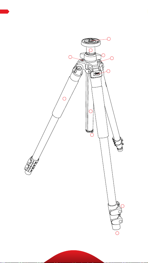
KEY FEATURES
A
B
D
G
C
E
F
H
I
J
K
4
Page 5

A
Dual 3/8″-1/4 ″-20 head mounting screw
B
Short split-column
C
Center column locking knob
D
Bubble level
E
Strap mount
F
Leg angle adjustment lock
G
Closed-cell foam grip
H
Grooved reversible center column
KEY FEATURES
I
Retractable and removable weight hook
J
Flip-style leg lock levers
K
Rubber feet
5
Page 6

OPERATION
OPERATION
1. Leg Length Adjustment
To adj us t the hei ght of eac h leg
independ ent ly, do t he follow in g:
1. Open t he fl ip-l ock lev er
2. Adjust the leg to th e desir ed
height.
3. Cl ose t he fl ip-lock to lock the
leg i n place.
2. Leg Angle Adjustment
For stable s upport when sho oting
on un even te rrai n, e ach leg can
be set a t a preset a ngle of 24°, 55°,
or 80°. To se t th e leg a ngle do th e
following:
• Pu ll t he adjustment loc k
outward.
• Set t he a ngle of the leg.
• Push the lock in to lock the leg at
that an gle .
6
Page 7
OPERATIONOPERATION
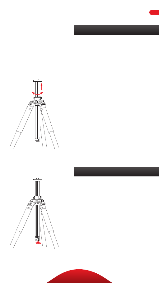
3. Center Column Adjustment
The sli di ng center colum n ca n
be used to adjust the height of
the c am era. F ul ly extending
the c ent er co lumn a ft er the legs
hav e been fu ll y ex ten ded will
pla ce the ca me ra at t he h igh est
position pos sible w ith th is
tripod.
1. T ur n th e center locki ng knob
counterclockwise.
2. Adjust the center colu mn to
the d esire d height .
3. Lock the column in pla ce
by turni ng the lo ck ing knob
clockwise.
Note: Make sure the colum n is
secure but do not overtighten to
avoid damaging the tripod.
4. Low-Angle Setup
There a re t wo ways t o adjust
the t ripod for low-an gle shots.
REVERSE THE CENTER COLUMN
Rev ersing th e center colu mn
allow s for mou nting t he camera
upsi de down in or der to get
close to t he ground or su rf ace.
To rever se t he ce nte r colum n do
the following:
7
Page 8

OPERATION
4. Low-Angle Setup (continued)
1. Wit h th e colum n lowered,
rem ove the bui lt-in weight hook
fro m th e bot tom of th e colum n
by turni ng it countercl ockwise
and pulling it out o f the colum n.
2. Tur n th e cen ter c olu mn locking
knob count erclockwise to
unloc k th e center colu mn .
Rem ove the center colu mn f rom
the t ripod.
3. Reverse the center column , li ne
up its g roove w ith the i nte ri or
nodule , an d in sert it up th rough
the b ottom of the tripod t op
plate.
4. Slide the center colu mn i nto
the d esire d positi on. Tu rn t he
cent er co lumn lock in g kn ob
clockwise to lock it at th e
desired height.
SPLIT THE CENTER COLUMN
Spl itting th e center colu mn
shortens t he colum n lengt h and
allow s for set ti ng t he tripod
legs at th ei r wides t angle. Th is
facil itates low-a ngle sho ts f rom
the t op of t he tripod. T o spl it the
cent er co lumn , follow th ese s teps:
1. Re move the weight hook from
the b ottom of the column by
turn in g it counterclock wi se and
pulling it out o f the colum n.
8
Page 9

OPERATION
2. Tur n th e cen ter c olu mn locking
knob count erclockwise to
unloc k th e center colu mn .
Rem ove the center colu mn f rom
the t ripod.
3. Using the s ma llest included
Al len wrench, loosen th e Allen
screw located near t he top of t he
cent er co lumn . When t he A llen
screw is l oosene d, u nscre w th e
top par t of the center colum n
and rem ove it fr om the column .
4. Put th e ma in c olu mn asi de.
Tighten the A llen sc rew wit h
the A llen wren ch so that th e
screw is fl ush wit h the surfa ce
of th e cen ter c olu mn. Inse rt t he
short colu mn i nto the t ripod.
Tighten the c ent er co lumn
locki ng knob s ecure ly.
Note: Extending the center column
may leave the tripod less stable.
5. Counterweight
When sh ooting in w indy
condit ion or whe n using a
teleph oto l ens, the st ab il ity of
you r ca mera is c ritic al . A built-i n
spr ing-loade d hoo k at the bottom
of th e cen ter c olu mn allow s yo u to
hang a counter weight , su ch as a
san db ag (not included) or lo aded
equ ipment bag (no t inclu ded), to
provide increased stability.
9
Page 10

OPERATION
6. Mounting a head
The tripod i nclud es a mo un ti ng
screw with a 1 /4″ screw on o ne
end a nd a 3 /8″ screw on t he o th er,
allow ing you to mou nt eithe r size
tripod h ead. To s witch between
the t wo sizes do th e followi ng:
1. Loosen the set sc rew that is n ex t
to th e mounting screw w ith the
included A ll en w rench .
2. Remo ve t he pl ate from
the t ripod by t ur ning it
counterclockwise.
3. Remo ve t he scre w, an d in ser t
the o ppo site end b ack int o th e
plate.
4. Replace t he plat e bac k onto th e
tripod b y tu rn ing it clock wi se.
5. Tight en the se t scr ew w ith the
Al len k ey.
To mo unt a hea d onto the tripod d o
the following:
1. Alig n th e botto m of the he ad’s
tripod m ou nt with t he t ripod’s
mounting screw.
2. Tur n th e head cl ock wise and
screw it onto t he mounti ng
screw unti l fully secured . Do not
ove rt ighten , si nce doi ng so m ay
cause damage.
3. Tighten t he three set screws
which clamp against the b ase
of th e tr ipod hea d with the
appr opriate A ll en key to ensure
ee ctive a nd secu re lock ing of
the h ead to the tr ipo d.
10
Page 11

Warni ngs:
• Please read and follow these instructions,
!
and keep this manual in a safe place.
• Make sure that this product is intact and
that there are no missing parts.
• Do not exceed the tripod’s maximum load
capacity (see tag on tripod).
• Ensure that all appropriate locks are
engaged when necessary.
• Tripod should only be used in temperatures
between -22° and 140° Fahrenheit.
• Do not operate in salt water. Dry tripod o if
it becomes wet.
• Remove the camera from the tripod during
transport.
• Keep out of reach of children.
• To avoid injury, always support the top of
the center column while adjusting height
with one hand and locking the knob with
the other hand.
• All photos a re for illustrative purposes only.
OPTIONAL ACCESSORIES
• Oben T S-110 Deluxe Padde d Neoprene Tripod
Str ap with z ippere d pocket
• Oben T S-10 0 Deluxe Tr ipod Str ap with S wivel
Hook
• Oben S TB -10 Tripod Ha mmock
Visit our website at ObenSupports.com
for more Oben products.
WARNINGS
11
Page 12

© Copyright 2015 The Gradus Group
All other trademarks are the property of their respective owners
www.obensupports.com
12
GG1
 Loading...