

Page 1
OASIS® VERSACOOLER®II MODELS PAC, PGAC, PFAC, P8AC, PG8AC, PF8AC, P8ACEE, PF8ACEE, PV8AC
SUNROC MODELS ADAAC, ADAFAC, ADA8AC, ADAF8AC, ADA8ACHF, ADAF8ACHF
A. INSPECTION
Inspect the carton and water cooler for evidence of rough handling and concealed damage. Damage claims should be filed with the carrier.
B. TO PUT WATER COOLER INTO SERVICE
1. Note: The following states require a licensed plumber to install cooler; AR, GA, MA, MI, OK, RI, SC, SD, TX, VT and WI. CA, KS, MN, NM and OR allow for a state-
registered installer or contractor as well. State and local plumbing codes may prohibit the use of saddle tapping valves for water line connection in some applications. All
connections must conform to applicable plumbing codes.
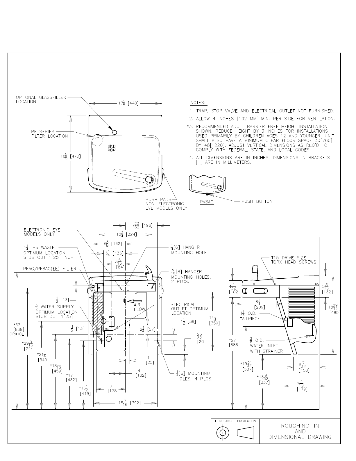
2. Locate and install plumbing and electrical service, if required, in accordance with the Roughing-in Drawing. Filter units have additional instructions on a label inside the
access panel. Read these before installing unit. This drinking water cooler is designed to be operated at a water supply line pressure of up to 100 psi (690 kPa). A pressure
regulator must be installed in front of the unit’s water inlet if the water pressure (including any possible pressure spikes) could exceed 100 psi (690 kPa).
3. FLUSH BUILDING WATER SUPPLY LINE BEFORE INSTALLING UNIT.
4. Install unit on the wall hanger. Wall hanger is shipped fastened to the back of the unit.
5. Install a trap in the waste line and a shut off valve in the water supply line. An in-line strainer is furnished in the “Water Supply” tube. Connect the “Water Supply” tube to
the shut off valve. This connection should not be a solder joint or flare connection to allow access to the strainer for service. To ease removal of the strainer, a sheet metal
screw may be lightly threaded into the open end. When the unit has an internal waste trap, the trap should be wrapped with insulating tape to prevent sweating. Use of the 13/4 diameter knockout for a waste line is not recommended because of a potential conflict with ADA* toe space clearance requirements. Check your local building code
inspector for approval.
6. Rotate the fan blade by hand to see that it is free of obstructions.
7. Check the available power supply against the water cooler data plate to assure correct electrical service. This drinking water cooler is intended to be connected to a 20A
minimum ground fault circuit interrupting (GFCI) device to meet UL requirements. Plug power supply cord into wall outlet. The rear most 1-3/8 diameter knockout in the
frame bottom is for an externally located electrical supply. Make sure the knockout hole edge is smooth and free of any burrs. Use of a Heyco bushing #2184 in the knocked
out hole is recommended in order to prevent damage to the service cord and to close up excess opening around the cord. Route the cord so it does not interfere with ADA*
space requirements.
8. To fill the cold water tank on water cooler versions, open the water supply line shut-off and push any one of the front or side pushbuttons to allow water to flow to the bubbler.
On the EE or HF model, actuate the solenoid by holding one hand approximately 3” from the infrared sensor. Run water until stream is free of bubbles.
9. To Adjust Bubbler Stream:
a) All Pushbutton models are equipped with a Cartridge Regulator. The P8AC, PAC, PG8AC, PGAC, PF8AC, PFAC, ADAAC, ADAFAC, ADA8AC and ADAF8AC
have a slot in the shelf below the Pushbuttons. Insert a screwdriver in this slot to adjust regulator. Turn adjustment clockwise to increase stream height. To access the
PV8AC adjustment, remove the Bezel and Button from the front of the cooler.
b) Electric Eye (EE or HF) models have a Regulator built into the Bubbler. If adjustment is needed, insert a 5/64 hex wrench approximately 1-1/8” into the bubbler nozzle
opening until it bottoms out and is seated in an adjust screw. Turn the adjust screw clockwise to reduce the stream height or counterclockwise to increase the height.
Note, less than one turn is required to go from a closed to a wide open flow. Do not over tighten the adjuster in the closed position as stripping the hex impression in the
adjust screw may result. Turn the adjuster 1/16 of a turn at a time.
10. On electric eye equipped models, place and then hold hand approximately 3” from the sensor to actuate the solenoid valve. After approximately 30 seconds run time, the
sensor will automatically shut off the solenoid valve. To reactivate, move hand away for an instant and then again place it in front of the sensor.
11. To adjust the beam range of the sensor (EE and HF models only):
a) Shut off the water and power supplies.
b) Remove the four screws from the top front.
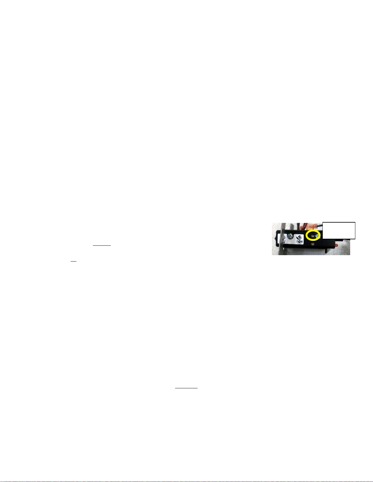
c) To adjust sensing distance, use a mini-screwdriver (3.0mm flat tip or smaller) and rotate adjustment potentiometer screw
on side of sensor. Turn clockwise to sense objects further away. This is represented by thicker end of curve on sensor
label. The screw can be turned a maximum of ¾ turns. The sensor has a maximum range of approximately 30”. It is
factory set at 15”.
d) NOTE: Do not turn adjustment as high as it can go. If you do the sensor will lock on until you turn the sensing distance back down.
e) There is an adjustable on-time delay of 0.5 seconds to prevent nuisance actuation of the solenoid valve should someone walk by. To adjust on-time delay, rotate blue
knob on timer clockwise. The maximum on-time delay is 1 second. After drinking, the water will shut off immediately after walking away. Maximum run time is 30
seconds should someone tamper with the sensor. NOTE: Walls with a reflective finish, i.e., ceramic tile, across from the sensor may cause false actuation no matter what
the sensor adjustment is for distance. Therefore, do not install the unit in such an area or dull the surface of the wall so it will not reflect light.
C. MAINTENANCE
The only maintenance operation required is the removal of dirt and lint from the condenser where used. Inspection should be made at 3-month intervals. Disconnect the power
supply cord, then clean the condenser with a small stiff non-wire or vacuum cleaner attachment brush when required. Observance of this procedure will insure adequate air
circulation through the condenser so operation is efficient and economical.
D. OVERLOAD PROTECTION
The compressor motor, where used, is equipped with an automatic reset protector which will disconnect the motor from the line in case of an overload.
E. LUBRICATION
This unit is equipped with a hermetically sealed compressor and requires no additional lubrication. The fan motor, where used, on this unit seldom needs oiling, but if required, a
few drops of SAE 10 oil should be used.
F. TO DISCONTINUE USE OF WATER COOLER
1. Close water shut-off valve.
2. Provide container to catch water to be drained.
3. On the push button model, disconnect the water supply line at the shut off valve and remove the tank drain plug. Actuate and hold in the pushbutton to open the solenoid
valve and completely drain the cooler. Disconnect the power supply cord.
4. On the EE model, disconnect the water supply line at the shut off valve and remove the tank drain plug. Actuate the solenoid, as explained in Step B8 to completely drain the
cooler. Disconnect the power supply cord.
5. Replace plug when draining is complete.
6. ALWAYS DRAIN ALL WATER WHEN FREEZING TEMPERATURES ARE ANTICIPATED AND BEFORE SHIPPING THE WATER COOLER.
*Americans With Disabilities Act
The warranty and the Underwriters' Laboratory Listing for this machine are automatically voided if this machine is altered, modified, or combined with any other machine or device.
Alteration or modification of this machine may cause serious flooding and/or hazardous electrical shock or fire.
EXCEPT AS SET FORTH HEREIN, THE MANUFACTURER MAKES NO OTHER WARRANTY, GUARANTEE OR AGREEMENT EXPRESSED, IMPLIED OR STATUTORY,
INCLUDING ANY IMPLIED WARRANTY OR MERCHANTABILITY OR FITNESS FOR A PARTICULAR PURPOSE.
Adjustment
potentiometer for
sensing distance
WARNING
222 East Campus View Blvd. • Columbus, OH 43235 U.S.A.
OASIS INTERNATIONAL
1-800-950-3226
www.oasiscoolers.com
OASIS is a registered trademark of LVD Acquisition, LLC dba Oasis International
A WBENC – Certified Women’s Business Enterprise © 2012 LVD Acquisition, LLC
030099-267 Rev D
Page 2
OASIS® VERSACOOLER®II MODELS
PAC, PGAC, PFAC, P8AC, PG8AC, PF8AC, P8ACEE, PF8ACEE, PV8AC
SUNROC MODELS ADAAC, ADAFAC, ADA8AC, ADAF8AC, ADA8ACHF, ADAF8ACHF
Page 3
®
VERSAFILLER
VERSAFILLER
Model PWSBF (retro fit) and
Model PWSBF (retro fit) and
P*SBF Family of Drinking
P*SBF Family of Drinking
Fountains/
Fountains/
Installation Instructions
Installation Instructions
The VersaFiller is an extension of the Aqua Pointe
directly above Versacooler
®
®
VersaFiller
VersaFiller
combo
combo
®
product line that mounts
®
®
I and II products. No additional electrical
®
connections are required.
If installed onto a refrigerated cooler, then chilled water can be dispensed
through the VersaFiller. Otherwise, room temperature water will be dispensed.
The VersaFiller is shipped partially assembled.
On the combo units, the cooler is plumbed and ready to attach to the
VersaFiller.
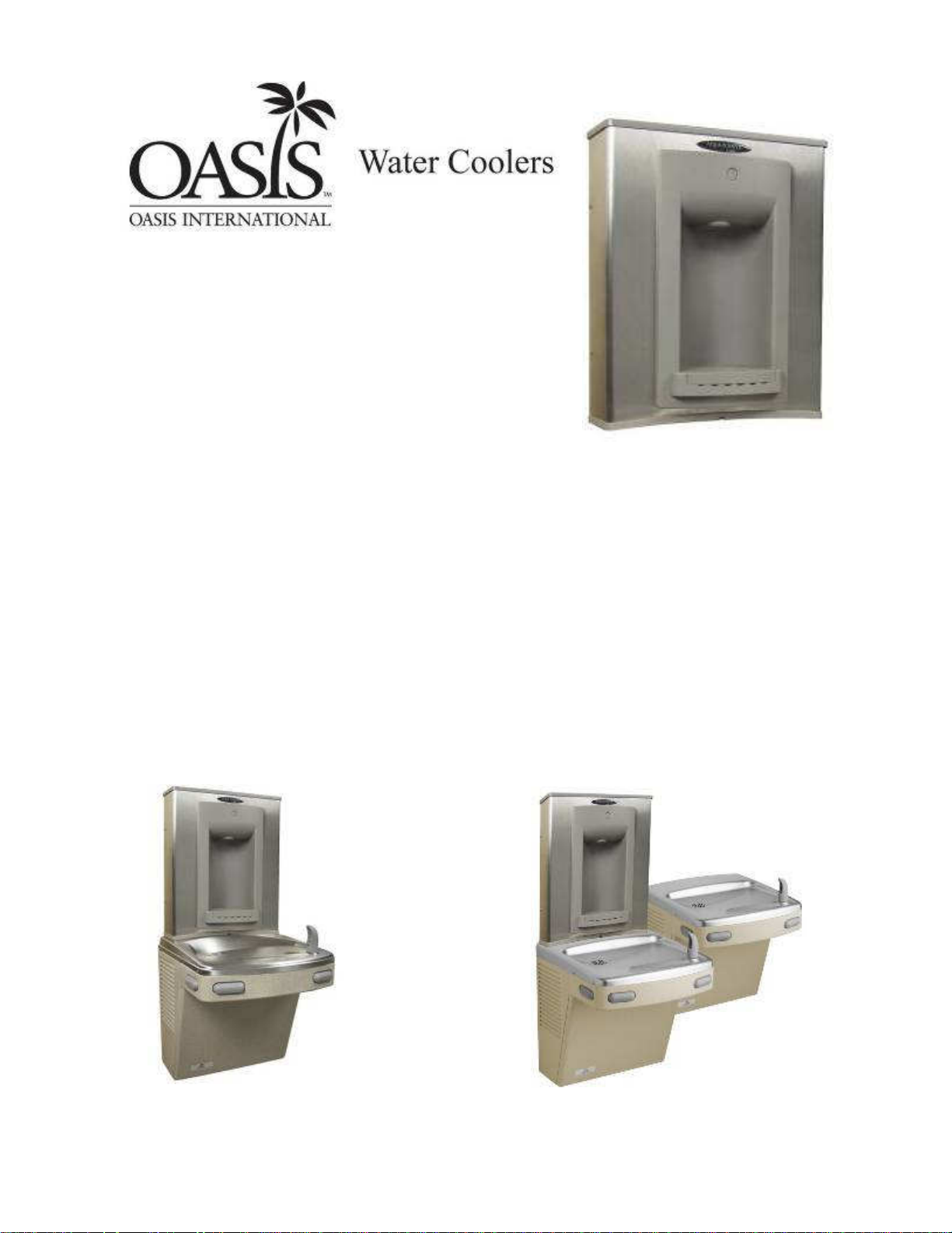
When completed, the finished assembly will look like this:
OR
Page 4
Section 1: Getting Started
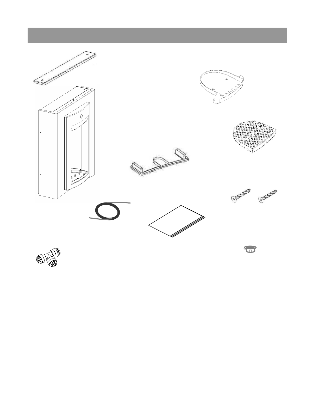
What’s Included:
(Top cap)
VersaFiller Sports
Bottle Filler- (with
wrapper, alcove
and top cap
installed onto the
frame)
Drip tray
Gasket
Anti splash grate
Quick connect
tee fitting
required on split
level units)
(only
3/8 drill bit that will drill through SS top (retrofit version only)
Electric drill
Small tubing cutter for copper tube
1/4 “ nut driver
# 2 Phillips screw driver
38” of ¼ OD plastic
tubing with 19” of
sponge tubing
insulation
with “Versafiller ready”
coolers)
(included
Tools required:
Anti Splash
grate screws (2)
Installation
instructions
Snap bushing
#15 torx bit driver
Page 5
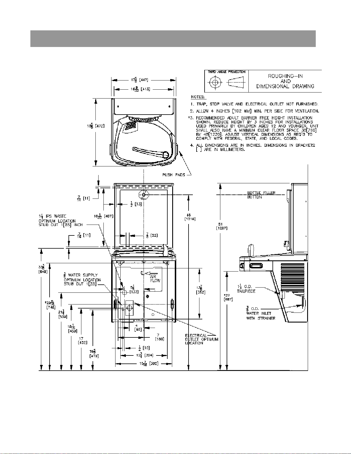
Section 2: Rough In Drawing
Oasis PWSBF: Versacooler®II Models PAC, P8AC with VersaFiller
Page 6
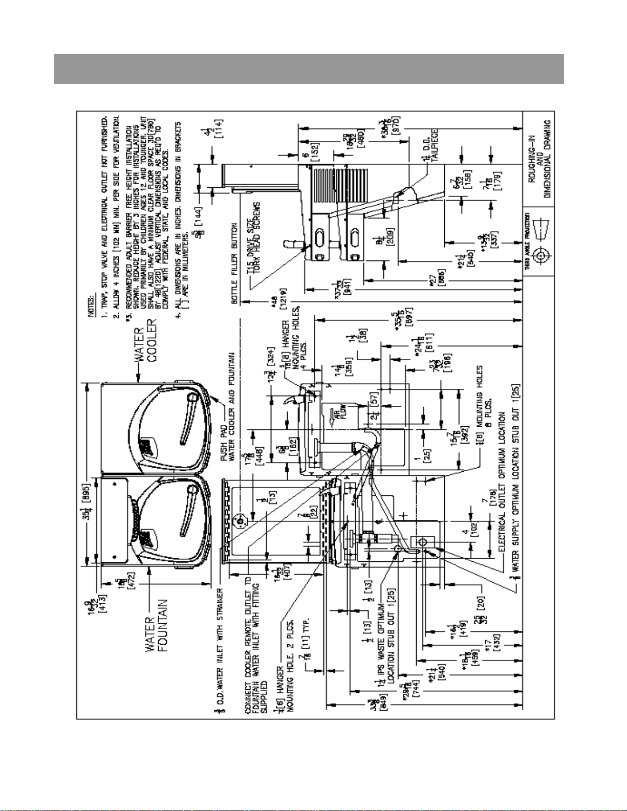
Section 2: Rough In Drawing
Oasis PWSBF: Versacooler®II Split Level Models with VersaFiller
* On split level models, the VersaFiller must be mounted
on the low unit in order to meet ADA guidelines.
Page 7
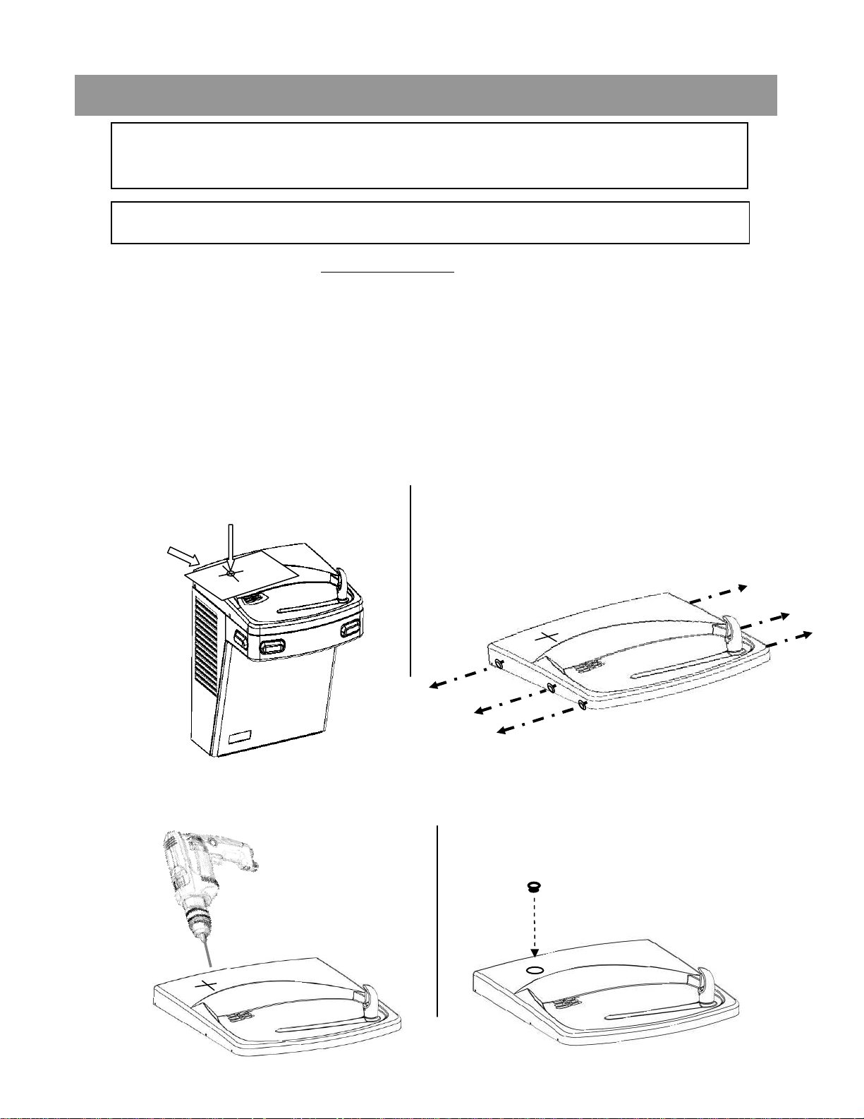
Section 3: Installation
Note: Proceed to Sect 3B Step 5 if the cooler is
purchased “VersaFiller ready”.
A: Drilling hole in the top for water line connection.
1. Disconnect power by UNPLUGGING unit. It might be necessary to
remove the front panel to get access to the power.
2. Turn OFF water supply to the unit. It might be necessary to remove the
front panel to access the water stop valve.
3. Place hole template onto cooler top so it is aligned with the left side of
unit and wall. SEE NEXT PAGE FOR TEMPLATE
4. Mark hole location
5. Remove top from unit.
Mark hole location.
Template
6. Using a 3/8 drill bit, drill a hole through top.
7. Install snap bushing into hole to protect tubing from being cut.
Drill
Remove top from cooler by
removing six #15 torx head screws
on sides of top.
Install bushing
Page 8
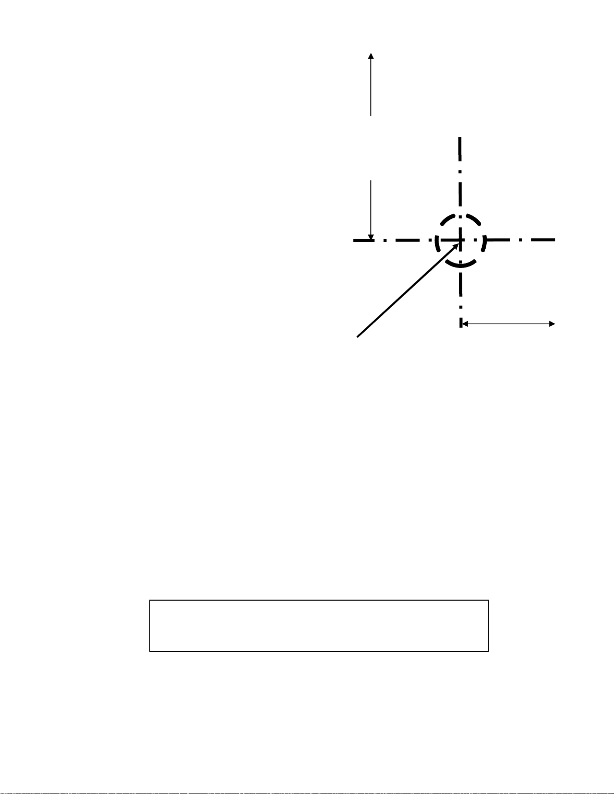
ALIGN THIS EDGE WITH LEFT EDGE OF COOLER TOP
Mark this center point on the
top. Remove the top from the
cooler. Then drill a 3/8 hole
through the top at the marked
3-1/4”
from
side
PLACE THIS EDGE AGAINST WALL
2-1/8”
from
back
center point.
USE THIS TEMPLATE TO MARK THE
HOLE LOCATION ON COOLER TOP
Page 9
Section 3: Installation
B: Connecting the water line
Note: If you are retrofitting the Versafiller to an existing cooler,
follow the instructions starting on the next page.
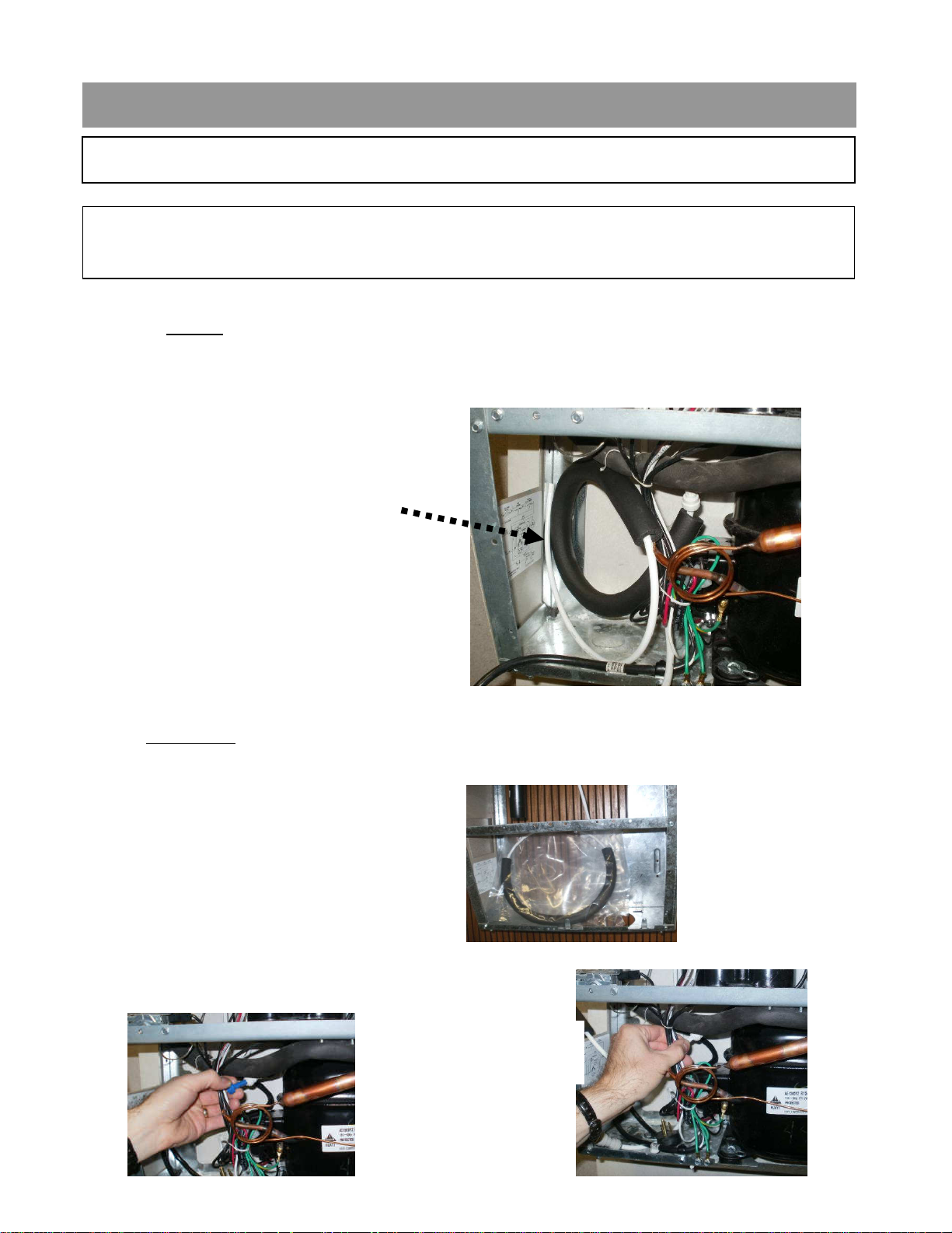
For the single “Versafiller ready” cooler, the tube to connect to the Versafiller
is found inside the access panel (the compressor compartment). This tube
supplies cold water from the cooling tank to the Versafiller.
¼” OD tube to connect
to Versafiller (no tee is
needed)
For split level “Versafiller ready” coolers, the tube to plumb in the
Versafiller is packaged in the dummy unit.
Remove tube from bag.
First, remove plug from
fitting on tank drain
Next, insert end of
tube into fitting.
Page 10
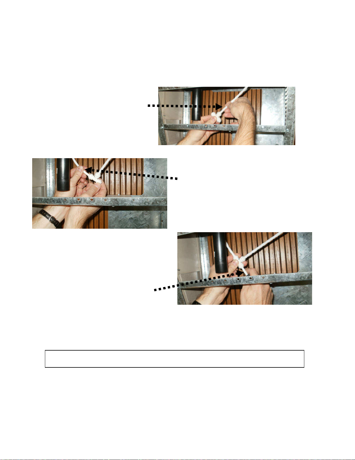
Tee and tube to Versafiller are packaged with PWSBF unit. One branch of
tee will supply valve on dummy unit. Other branch of tee will connect to
Versafiller. Note: “Versafiller ready” single units do not use tee since
water line from cooling tank only supplies water to bottle filler.
Tube to connect valve
on dummy unit
Tube to connect
Versafiller
Tube to connect chilled
water to dummy unit
and Versafiller
Go to Step 5 “Final steps for both product families:”
Page 11
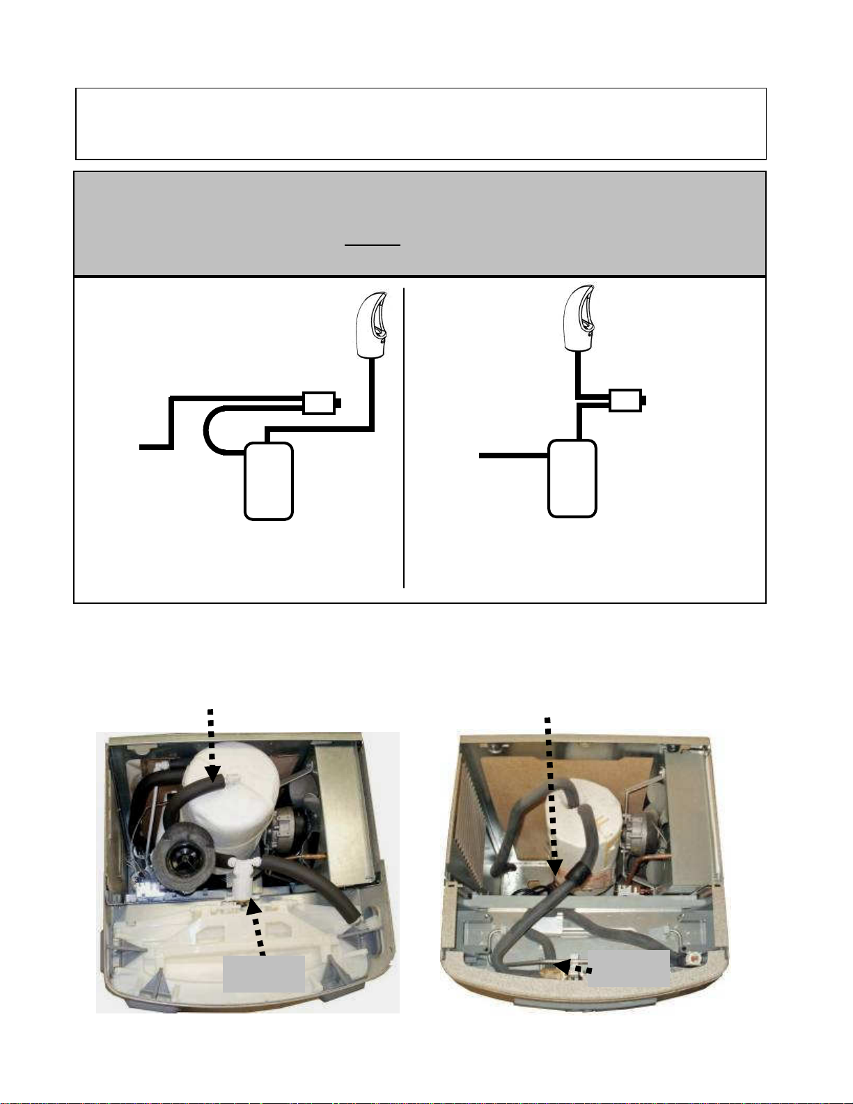
To retrofit the Verafiller to an existing unit, follow the
instructions below:
If the cooling tank is non-pressurized, then go to the “Pressurizing the
cooling tank” addendum section. Otherwise, proceed to step 1 below.
Non-pressurized units are single units made since December of 2009.
Refer to the schematic below to identify the system that you have.
Water
valve/
regulator
tank
Supply
Water
Water
valve/
regulator
tank
Cooling
NON-
PRESSURIZED
COOLING TANK
Supply
Water
Cooling
PRESSURIZED
COOLING
TANK
1. With the cooler top removed, find the tube going from the cooling
tank outlet to the valve. The TEE fitting (supplied) will need to
connect between the cooling tank and valve.
Outlet Tube (insulated plastic)
Outlet Tube (insulated copper)
Valve
P8AC family
Valve
P8AM family
Page 12
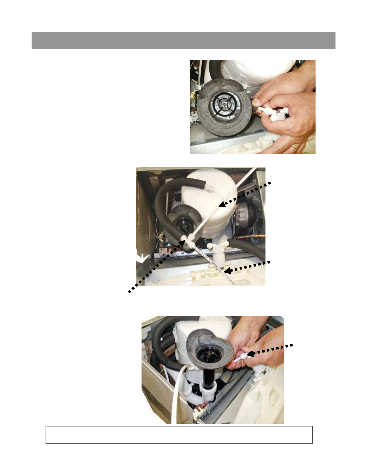
Section 3: Installation: For the P8AC Version: Versacooler II
2. Disconnect tubing from the
elbow on the valve.
3. Using the 38” piece
of tubing provided,
cut 6” and install it
on the end of the
TEE. Install the
remaining tubing
onto the branch of
the TEE. Connect
the other end of the
TEE to the tank
outlet tubing (tube
that was
disconnected from
the elbow).
TEE
32” tubing
6” tubing
4. Route the TEE and
tubing under the
waste drain and
connect the 6” length
to the water valve
elbow.
Go to Step 5 “Final steps for both product families:”
Water
valve
elbow
Page 13
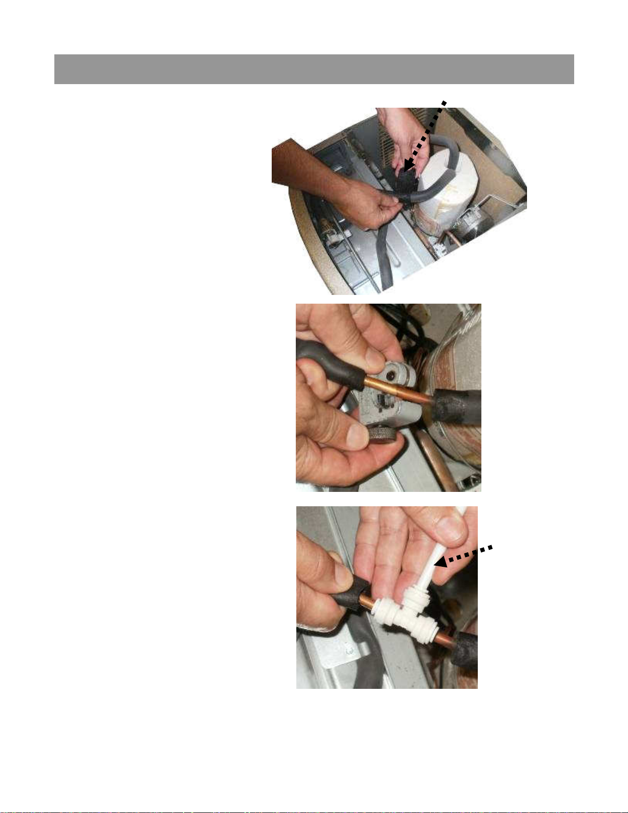
Section 3: Installation: For the P8AM Version: Versacooler I
Remove tar tape
2. Remove tar tape from
the insulation on the
outlet tube.
3. Pull back insulation and cut
the copper tube with a
tubing cutter. Cut where
there is at least 1 inch of
straight tubing on each side
of the cut.
4. Install TEE fitting by
connecting the copper
tubing to each end. Then
install the 32” piece of
plastic tubing to the TEE
branch.
32” plastic
tubing
(supplied)
Page 14
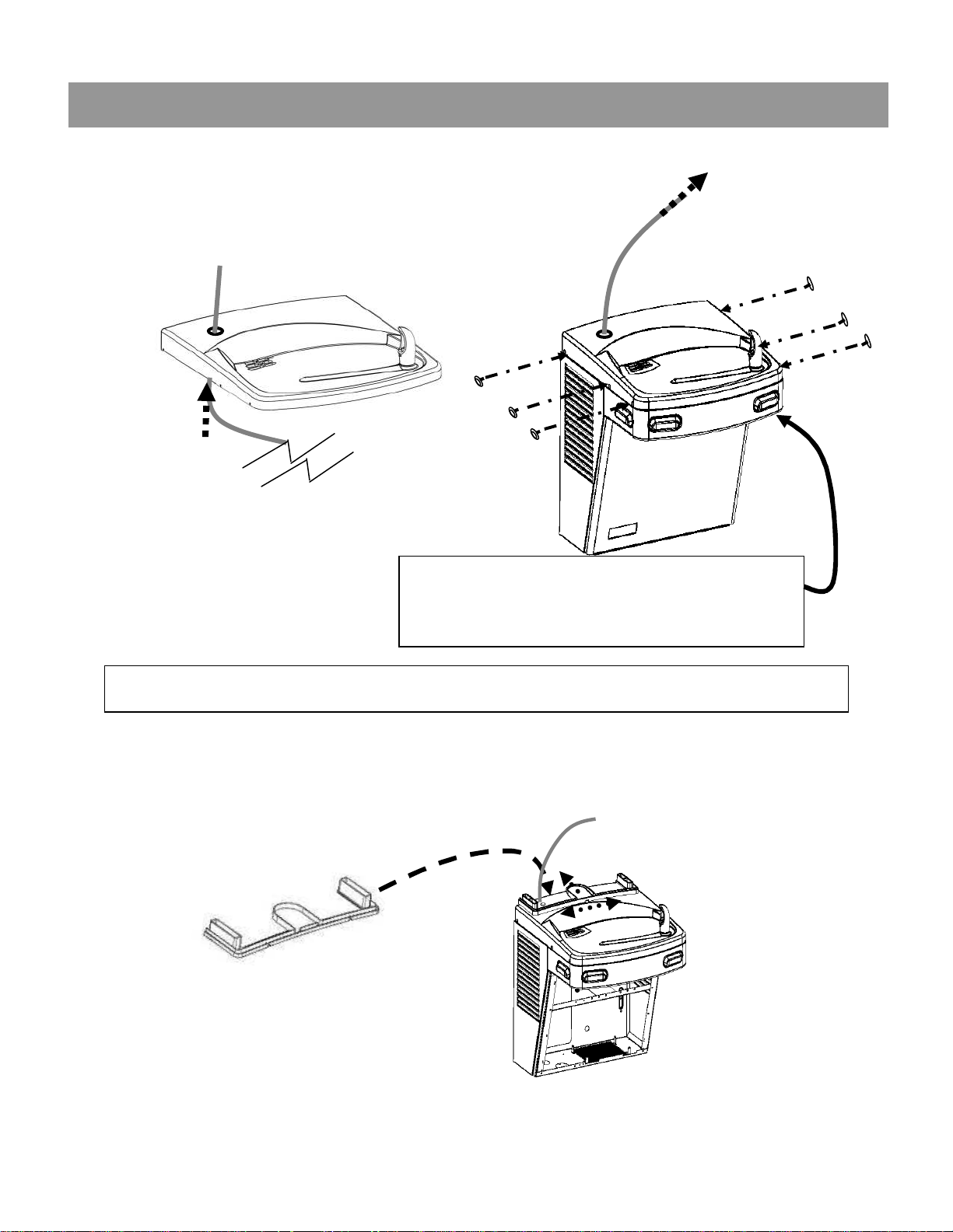
Section 3: Installation: Final steps for both product families:
5. Feed tubing up through the top and attach the
top to the cooler.
TIP: For the P8AM, it is easier to
connect the outlet tube to the bubbler if
the front nose is removed.
C: Mounting the frame to the wall
1. Place rubber gasket on top of the cooler so it is centered left/right
and against the wall.
Page 15
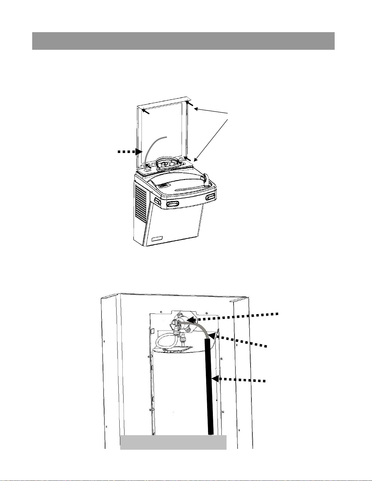
Section 3: Installation
2. Set the wall frame onto the gasket. Center it left/right and push it against
the wall and mark hole locations for wall fasteners. The gasket will set the
frame at the proper height.
Use mounting slots that
will provide the proper
securing location.
Make sure to pull
the plastic tubing
up through the
hole in the frame.
3. Secure frame to the wall with fasteners (not provided). Pull plastic
tubing up through the hole in the frame.
4. Slide sponge tubing insulation over water line. Connect the tubing to
the INLET elbow on the back of the VersaFiller assembly.
Connect tube
to elbow on
the valve
Plastic tubing
Sponge tubing
insulation
Rear view of VersaFiller
Page 16
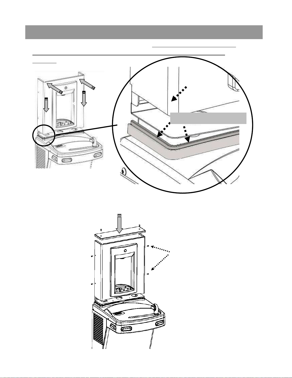
Section 3: Installation
5. Set the VersaFiller cabinet into place. MAKE SURE the cabinet fits
into the groove in the rubber gasket on both sides and front of the
wrapper.
VersaFiller
cabinet
Groove in the gasket
6. Attach VersaFiller assembly and top cap to the frame using the six
(6) torx screws.
Torx screws
Page 17
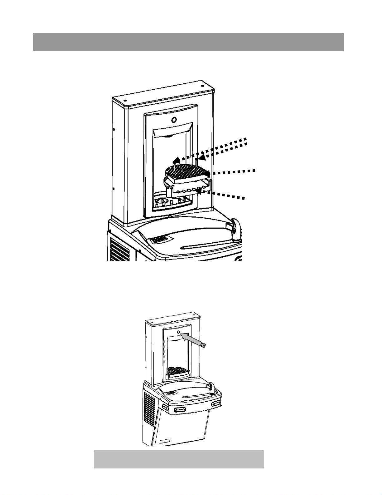
Section 3: Installation
7. Install the drip tray and anti-splash grate into the alcove area
and secure with the two (2) stainless steel phillips head screws.
Anti-splash grate
screws (provided)
Anti-splash grate
Drip tray
8. Turn ON water supply and check for leaks. Press the activation button
and release any trapped air from the system. Plug in the power cord and
replace the front panel IF it was removed earlier.
Press
INSTALLATION COMPLETE
Page 18
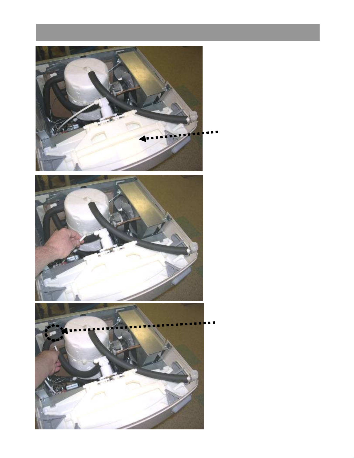
Addendum Section: Pressurizing Cooling Tank
The water should
already be turned OFF
and the power
disconnected.
Unit as it appears with
top removed
STEP 1
Unplug un-insulated water
line from water valve inlet
(JG elbow located left side
of water valve facing the
front of the cooler). Set
tubing aside (careful to not
contaminate water contact
end).
STEP 2
Unplug tubing from JG
elbow leading to
cooling tank inlet.
Page 19
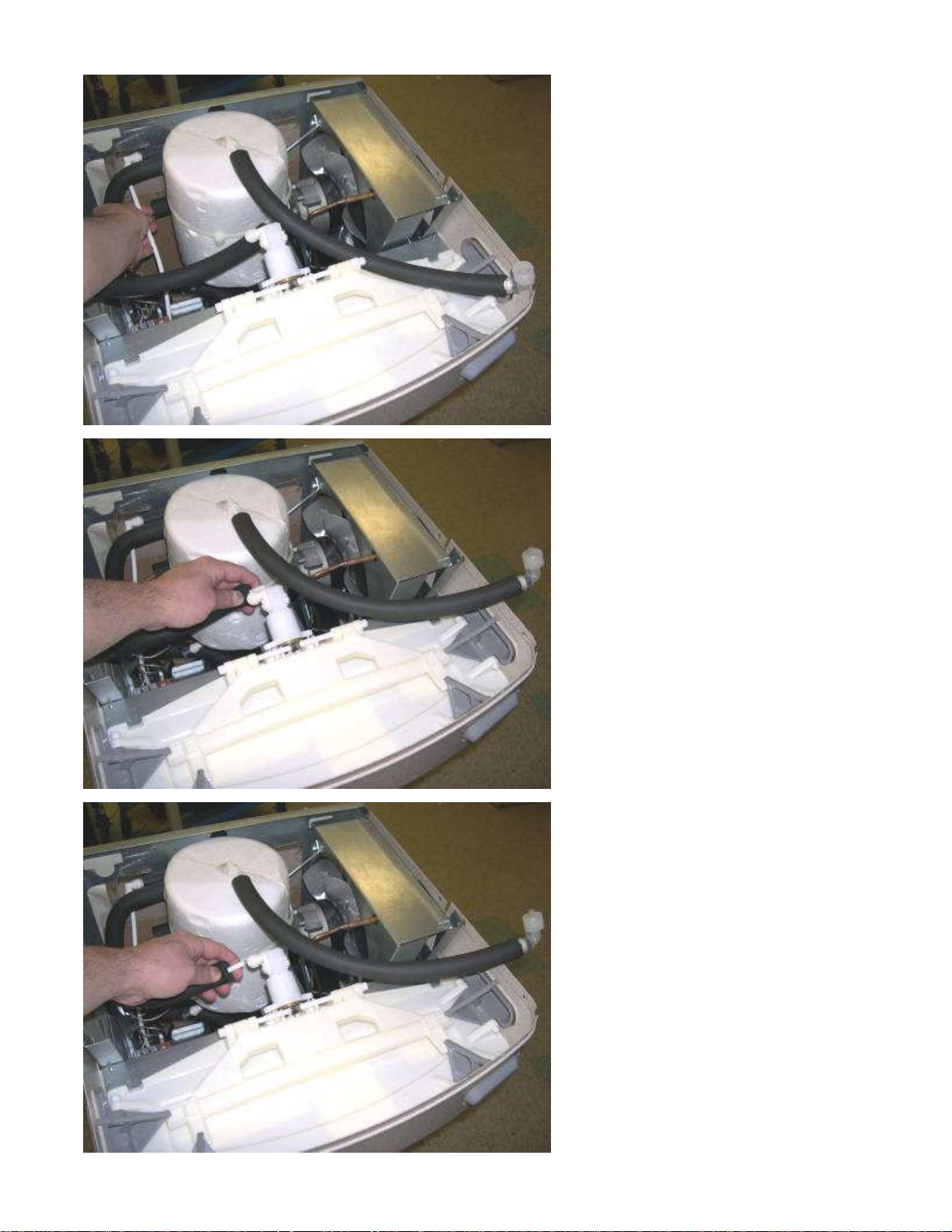
STEP 3
Plug un-insulated tubing that
was removed in step 1 into
JG elbow leading to the
cooling tank from step 2.
STEP 4
Unplug tubing that is
connected to the
water valve outlet (JG
elbow located on the
right side of valve
facing the cooler).
STEP 5
Connect tubing
from step 4 to JG
elbow on the left
side of the valve.
Page 20
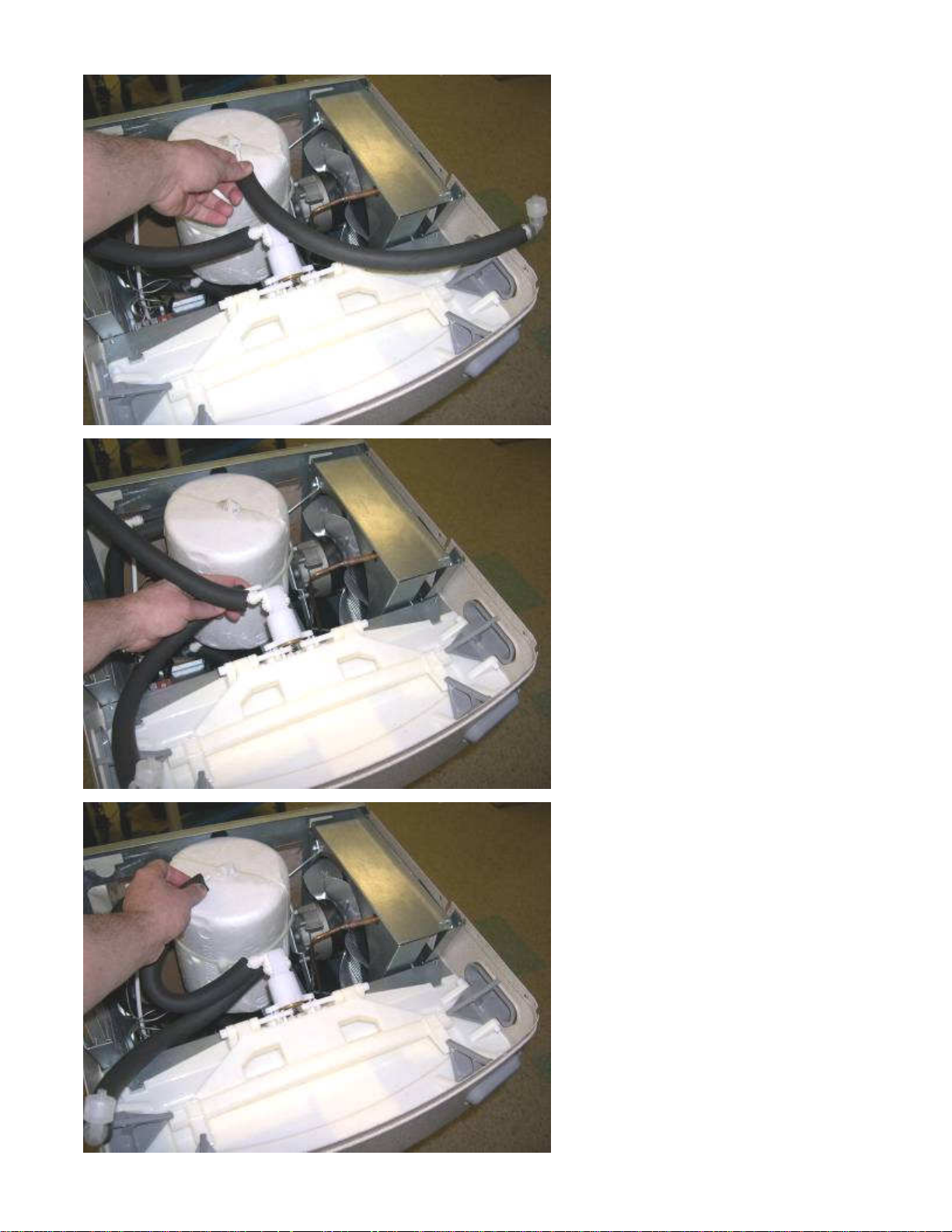
Step 6
Unplug JG tubing
from the cooling
tank outlet. Do
not set it down.
Step 7
Using tubing
removed in step 6,
plug into JG elbow
on the right side of
the valve. (be sure
to rout the tubing
under existing
tubing installed in
step 4 as shown)
Step 8
Using tubing that is
connected to the JG
elbow left side of
valve (done in step
4), and plug the
other end to the JG
fitting at the top of
the cooling tank.
Return to Section 3 B
“Connecting the water line”
Page 21
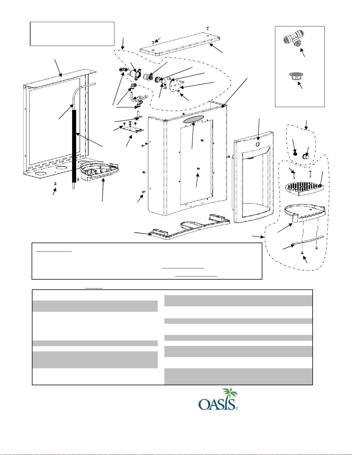
1
036190-002
ALCOVE, PWSBF
17
028706-036
WASHER/SPACER/GASKET-NON META
2
036691-001
WRAPPER, PWSBF STN2
18
026670-007
SCREW, HEX HD MACHINE
4
036049-002
SCREW, FLAT HEAD TAPPING
20
036479-001
FILL TUBE ASSY
6
036695-001
TRAY, GRILLE DRIP
22
026642-003
SCREW, HEX HD TAPPING
7
036697-001
DRIP TRAY BOTTOM CAP
23
031206-005
INSERT, NAMEPLATE AQUAPOINTE
10
036689-001
GASKET, PWSBF
26
036687-001
FRAME, PWSBF
11
036191-002
DRAIN, MSBF, SHORT
27
027189-007
BUSHING, SNAP
12
035990-001
HOLDER, CARTRIDGE STEM CON
28
029199-103
FTG, PP UNION TEE WHITE
13
029967-002
CARTRIDGE
29
030152-031
TUBE, PE CUT LENGTH WHI
14
A020957
NUT, RETAINING PLASTIC
30
017681-008
INSULATION, SPONGE TUBING
33
036231-001-SP
VALVE ASSEMBLY, PWSBF DISPENSE-SERVICE
EXPLODED PARTS
BREAKDOWN
33
25
26
24
22
11
20
22
30
19
12
21
25
29
16
13
23
18
22
14
17
15
3
28
2
27
1
32
9
8
4
6
10
31
Accessories:
Vandal resistant screw kit: P/N 036704-001, includes torx bits and replacement screws for items 4 and 25.
Gasket, Sunroc/Haws : P/N 036689-101 (replaces item 10): KIT P/N 036752-001
Gasket, Elkay/Halsey Taylor P/N 036689-201 (replaces item 10 ): KIT P/N 036752-002
5
7
*Items highlighted in GRAY are available as service parts
3 036686-001 CAP, PWSBF 19 028481-101 FTG, PP UNION ELBOW WHT
5 036688-001 TRAY, DRIP PWSBF 21 036209-001 BRACKET, FILL TUBE SUPPORT
8 036194-002 BUTTON, PWSBF 24 030152-046 TUBE, PE CUT LENGTH WHI
9 034649-001 SPRING, MSBF 25 031875-003 SCREW, BUTTON HD TAPPING
15 036690-001 BRACKET, VALVE PWSBF 31 036701-001 DRIP TRAY ASSEMBLY-SERVICE
16 030176-002 PLUG, HOLE 32 036702-001 BUTTON ASSEMBLY, PWSBF-SERVICE
P/N 030099-412 Date: 1/2014 Rev F
© 2014 LVD Acquition, LLC
Oasis, Aqua Pointe, Versacooler and VersaFiller are registered trademarks of
LVD Acquisition.
Haws is a registered trademark of HAWS Corporation.
Elkay and Halsey Taylor are registered trademarks owned or licensed by Elkay
Sales Inc. and/or its parent Elkay Manufacturing Company
Oasis International
222 East Campus View Blvd.
Columbus, OH 43235
614-861-1350
www.oasiscoolers.com
22
 Loading...