

Page 1
1310836-07
MAR 02 2016
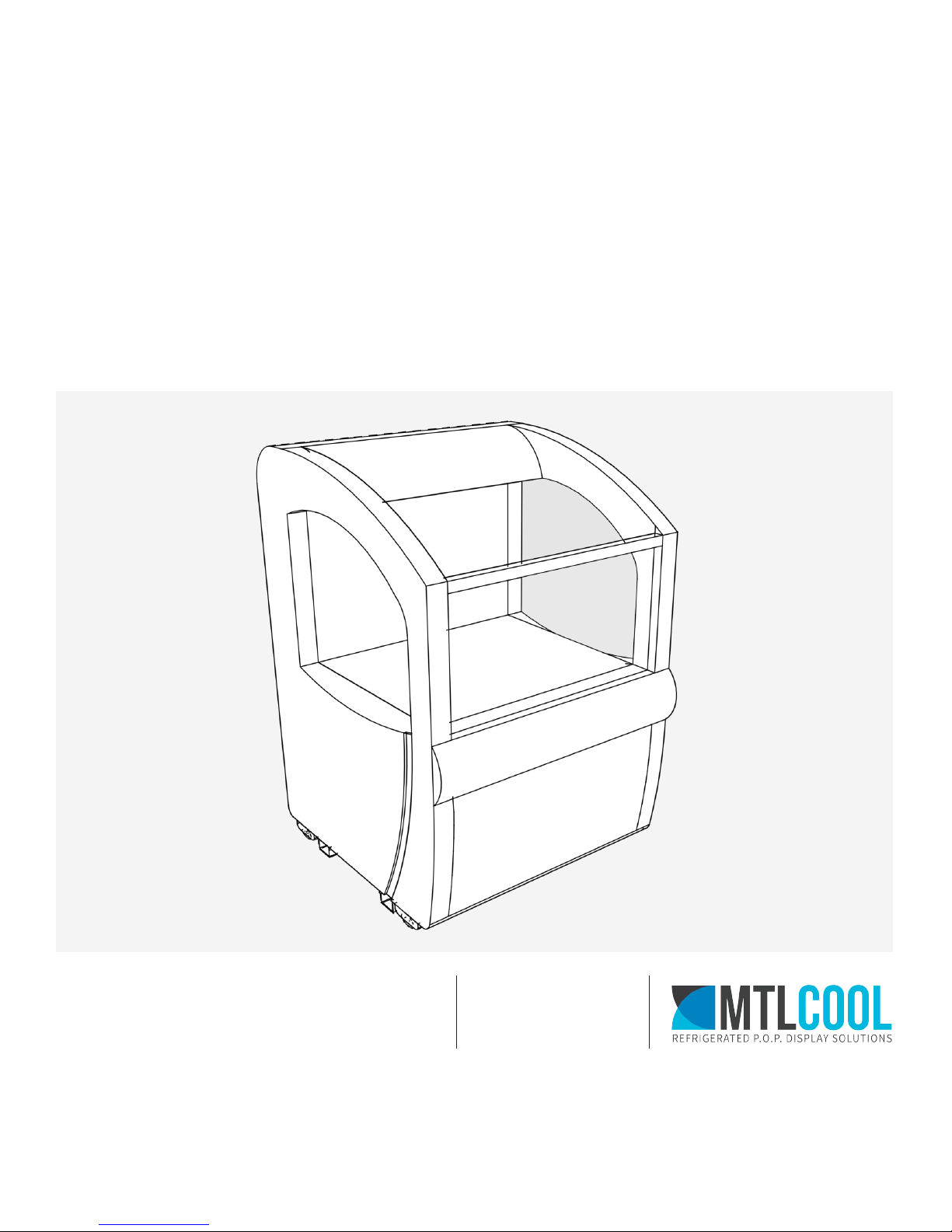
OASIS
Open Air Cooler
User Manual
OASIS-30 & OASIS-36 Models
Oice: 1.888.685.9959
Tech Support: 1.888.685.8324
www.mtlcool.com
7880 Boul. Industriel,
Chambly, Quebec
J3L 4X3
Page 2

Page 3

TABLE OF CONTENTS
UNPACK AND INSPECTION �������������������������������������������������������������������������������������������������������������������������������������������������� 1
PALLET REMOVAL ������������������������������������������������������������������������������������������������������������������������������������������������������ 1
SAFETY AND PRECAUTIONS ������������������������������������������������������������������������������������������������������������������������������������������������ 2
PROPER DISPOSAL OF THE REFRIGERATOR ������������������������������������������������������������������������������������������������������������ 2
REFRIGERANT DISPOSAL ������������������������������������������������������������������������������������������������������������������������������������������ 2
HOW TO CONNECT ELECTRICITY ������������������������������������������������������������������������������������������������������������������������������ 2
SAFETY PRECAUTIONS ���������������������������������������������������������������������������������������������������������������������������������������������� 2
MAINTENANCE ����������������������������������������������������������������������������������������������������������������������������������������������������������� 3
INSTALLATION ��������������������������������������������������������������������������������������������������������������������������������������������������������������������� 4
INSTALLATION REQUIREMENTS ������������������������������������������������������������������������������������������������������������������������������� 4
ELECTRICAL REQUIREMENTS ����������������������������������������������������������������������������������������������������������������������������������� 4
ADDING/REPLACING ARTWORK IN THE HEADER ����������������������������������������������������������������������������������������������������� 4
APPLYING DECAL GRAPHICS ON GLASS ������������������������������������������������������������������������������������������������������������������� 4
WARRANTY INFORMATION �������������������������������������������������������������������������������������������������������������������������������������������������� 6
ANNEX 1� CONTROLLER SETTINGS ������������������������������������������������������������������������������������������������������������������������������������� 8
SF-102 ������������������������������������������������������������������������������������������������������������������������������������������������������������������������ 8
CAREL PJEZ ���������������������������������������������������������������������������������������������������������������������������������������������������������������� 9
1310836-07 | MAR 02 2016
Page 4

Page 5
UNPACK & INSPECTION
All MTL Cool equipment is packaged in a manner to
prevent from damage in transport and for the unit to
remain visible for a visual inspection. Equipment is
palletized, shrink wrapped and sometimes boxed.
WARNING
At time of delivery, carefully examine the
equipment for any damage that may have
occurred in transit.
All damages should be noted on the bill of
lading or delivery receipt.
The equipment should be unpacked as soon as possible.
Verify that all equipment including internal components
and glass were not damaged in transit.
If any damage is found please contact MTL Cool at 1-888-
685-8324 immediately to report the damage. If possible
please take pictures of the damage.
PALLET REMOVAL
The Oasis Grab N’ Go cooler is secured to the pallet
beneath it.
Please follow the instructions below to safely detach the
cooler from the pallet
Locate the 8 Phillips head screws securing the wood
1
blocks to the pallet. There are 4 on each side of the cooler.
1
2
Unscrew the 8 screws using a Phillips head screw driver
2
or power drill.
Slide the wood blocks out of the tracks. The cooler is
3
now detached from the pallet.
1310836-07 | MAR 02 2016
3
Unpack & Inspection
1
Page 6
SAFETY & PRECAUTIONS
DANGER!
RISK OF CHILD ENDANGERMENT
PROPER DISPOSAL OF THE REFRIGERATOR
To avoid the possibility of child endangerment, please
take the following precautions before throwing away the
refrigerator:
• Leave the shelves in place so that children may not
easily climb inside.
• Never allow children to operate, play with, or crawl
inside the refrigerator.
!
not le exposed or dangling to prevent accidental injury.
SAFETY PRECAUTIONS
Keep the unit upright during transportation. If the unit is
tilted during transportation, please allow the unit to sit
upright for a minimum of 2 hours before plugging in the
unit.
Ensure that there is a minimum of 3 inch of space behind
the unit for air circulation.
(A metal “spine” may be pre-installed on the rear of the
cooler ensuring there is always space behind the cooler).
Place the cooler on a level surface.
REFRIGERANT DISPOSAL
All refrigeration products contain refrigerants, which under
the Guidelines of Federal Law must be removed before
disposal of product. It is the consumer’s responsibility to
comply with federal and local regulations when disposing
of this product.
• Never clean refrigerator parts with ammable uids.
The fumes can create a re hazard or explosion.
• DO NOT store or use gasoline or any other ammable
vapors and liquids in the vicinity of this or any other
refrigerator. The fumes can create a re hazard or an
explosion.
HOW TO CONNECT ELECTRICITY
This refrigerator should be properly grounded for your
safety.
It is your responsibility and obligation to have the proper
outlet installed. The power cord of this refrigerator is
equipped with either three-prong plug (115v) 5-15P plug.
DO NOT, under any circumstances, cut or remove the third
ground prong from the power cord supplied.
Place the unit in a dry environment for optimal
performance.
Do not obstruct the ventilation both at the bottom front
and interior of the cooler.
Before using this freezer/refrigerator, it must be positioned
and installed in accordance with the installation
Instructions (see page 4).
DO NOT allow children to climb, hang or stand on the
shelves in the freezer/refrigerator. Serious damage could
be caused to both the children and the unit.
DO NOT touch the cold surfaces in the freezer
compartment when hands are damp or wet. Skin may
stick to these extremely cold surfaces.
Before cleaning or making any repairs, unplug the freezer/
refrigerator.
Repair or replace immediately all power cords that have
become frayed or otherwise damaged.
DO NOT place the cooling cabinet on top of the electrical
plug.
The cord should be secured behind the refrigerator and
2
DO NOT use an extension cord with this appliance. If the
Safety & Precaution
1310836-07 | MAR 02 2016
Page 7

power cord is too short, have a qualied electrician or
service technician install an outlet near the appliance. Use
of an extension cord can negatively aect the performance
of the unit. The refrigerator should always be plugged
into it’s own individual electrical circuit (unless specied
otherwise), which has a voltage rating that matches the
rating plate.
MAINTENANCE
The cooler should be cleaned once a week with power
supply disconnected. In cleaning, please use mild rinsing
water or non-corrosive cleanser essence.
It is recommended that preventative maintenance be
performed on the unit every 6 months.
When removing the refrigerator from the wall, be careful
not to roll over or damage the power cord.
This unit is covered by a 1 year limited warranty.
1310836-07 | MAR 02 2016
Safety & Precaution
3
Page 8
INSTALLATION
X
INSTALLATION REQUIREMENTS
DO NOT place the cooler in a location with air dras that
1
could disrupt the air curtain
DO NOT place the cooler in a location with ambient
3
temperatures over 75°F or 50%RH
ELECTRICAL REQUIREMENTS
• A dedicated power line from the breaker box
• 20 Amp Breaker
There must be at least 2 inches of space behind the unit
2
at all times to ensure proper air ow.
Note: Even though
there are no vents
at the back of
the Oasis, the air
intake will come
from behind the
unit.
Cooler should not be placed near other equipment that
4
can be expelling heat. (example, Chicken warming stations)
Please consult factory for voltage drop calculations based
on line lengths, see below.
• The wire gauge should be suicient to limit voltage
drop under 15 amp load to 3%.
WIRE GAUGE FOR 3% VOLTAGE DROP IN SUPPLY CIRCUITS
Amps 20 30 40 50 60 70 80 90 100 120 140 160
2 14 14 14 14 14 14 14 14 14 14 14 14
3 14 14 14 14 14 14 14 14 14 14 14 14
4 14 14 14 14 14 14 14 14 14 14 14 12
5 14 14 14 14 14 14 14 14 14 12 10 10
5 14 14 14 14 14 14 14 14 12 10 10 10
7 14 14 14 14 14 12 12 12 10 10 10 8
8 14 14 14 14 12 12 12 10 10 10 8 8
9 14 14 14 12 12 12 10 10 10 8 8 8
10 14 14 14 12 12 12 10 10 10 8 8 8
12 14 14 12 12 10 10 10 8 8 8 8 6
14 14 14 12 10 10 10 8 8 8 6 6 6
16 14 14 12 10 10 8 8 8 8 6 6 6
18 14 12 10 10 8 8 8 8 8 8 8 5
20 14 12 10 10 8 8 8 6 6 6 5 5
25 12 10 10 8 8 6 6 6 6 5 4 4
30 12 10 8 8 6 6 6 6 5 4 4 3
35 10 10 8 6 6 6 5 5 4 4 3 2
40 10 8 8 6 6 5 5 4 4 3 2 2
45 10 8 6 6 6 5 4 4 3 3 2 1
50 10 8 6 6 5 4 4 3 3 2 1 1
4
Installation
1310836-07 | MAR 02 2016
Page 9
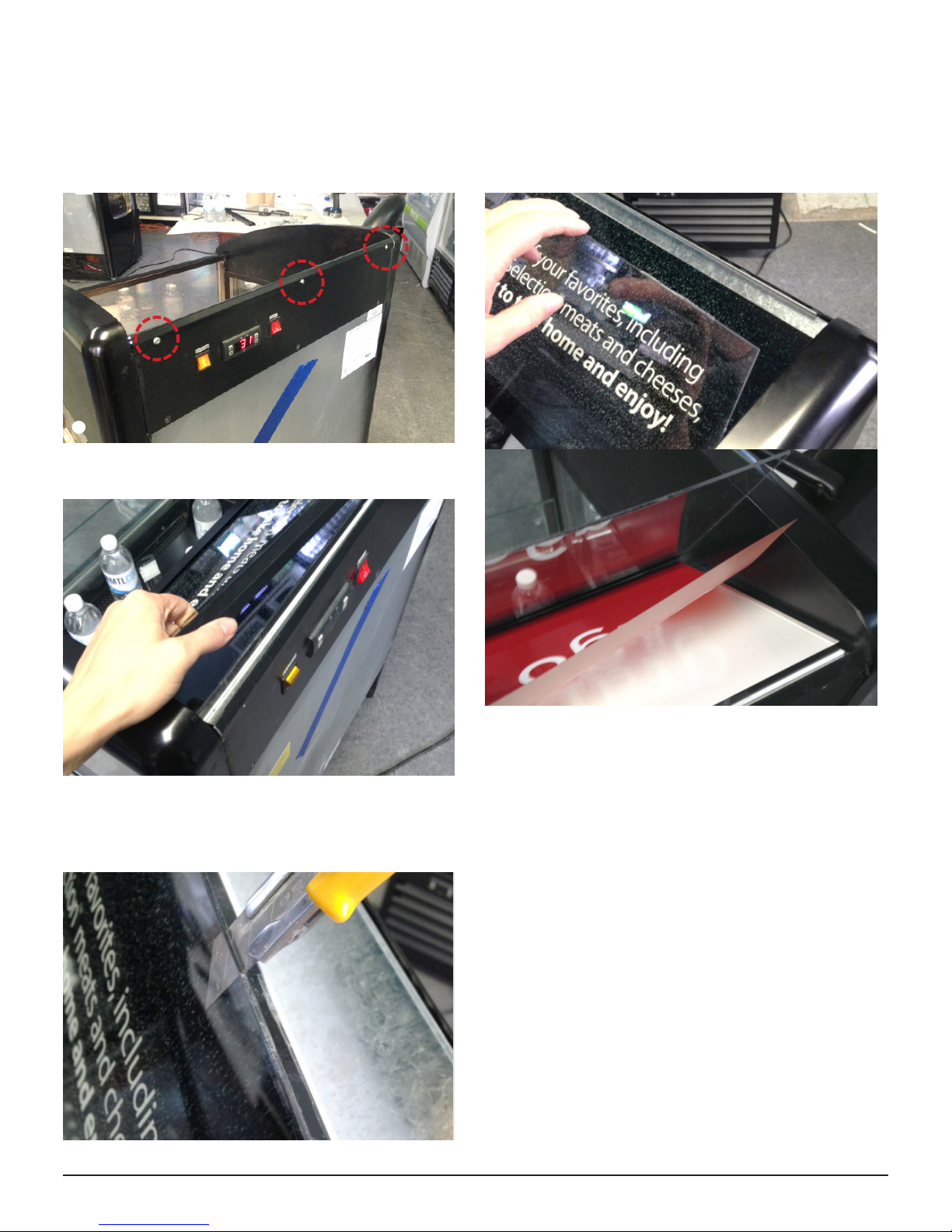
ADDING OR REPLACING THE ARTWORK IN THE
HEADER OF THE UNIT
Power o & unplug Oasis unit
1
Remove top three screws at the back of the unit ▼
2
2
Remove the header frame ▼
3
Li the top sheet, remove the artwork and replace it. ▼
5
The artwork is sandwiched between two sheets of
4
plastic. Use a knife or box cutter to cut the tape holding
the two sheets together. ▼
x x
Reassemble: Replace the tape along the edges of the
6
plastic sheets & secure the header frame with the three
screws.
APPLYING DECAL GRAPHICS ON GLASS
Wet the glass and the sticky side of the graphics with
1
soapy water (a small amount of soap diluted with water in
a spray bottle, or use Windex)
Apply the graphics. The soapy water allows you to move
2
them around on the glass until they are in the proper
position.
Use a squeegee or a malleable straight edge to remove
3
all excess water and air bubbles beneath the graphics.
Once dry, verify that the edges of the graphics are
4
properly glued. Give the edges a nal press if needed.
1310836-07 | MAR 02 2016
Installation
5
Page 10
WARRANTY INFORMATION
ONE YEAR PARTS AND LABOUR WARRANTY:
MTL Technologies, Inc. (“MTL Cool”) warrants that every
new MTL Cool refrigerated display cooler, the cabinet,
and all parts shall not contain any defects in material
or workmanship, under normal and proper use and
maintenance service as specied by MTL Cool and upon
proper installation and startup in accordance with the
instructions provided with each MTL Cool unit. Except as
otherwise set forth herein, MTL Cool’s obligation under
this warranty is limited to a period of one year from the
date of original shipment.
Any parts covered under this warranty that MTL Cool
determines to have been defective within the one year
Warranty Period is limited to the repair or replacement,
including labour charges of defective parts or assemblies.
The labour warranty shall include standard straight
time labour charges only and reasonable travel time as
determined by MTL Cool.
MTL Cool must authorize all labour. All costs not covered
under warranty will be the responsibility of the original
purchaser.
Our obligation under this warranty shall be limited to
repairing or replacing F.O.B. factory any of such products,
which proves thus defective which our examination shall
disclose to our satisfaction to be defective.
Any part returned to the company under the terms of
this warranty must be accompanied by a record of the
cabinet model, the MTL Cool serial number located on
the back of the unit, and a return authorization number,
and such return shall be on the basis of TRANSPORTATION
CHARGES PREPAID BY MTL COOL.
Improper operation due to low or high voltage conditions,
inadequate wiring, and accidental damage are not
manufacturing defects and are strictly the responsibility of
the purchaser.
The term “original purchaser” as used herein shall
be deemed to mean that person, rm, association of
corporation for whom the Refrigeration Unit referred to
herein is originally purchased.
NO CLAIMS CAN BE MADE AGAINST THIS
WARRANTY FOR LOSS OF PRODUCT
These warranties are in lieu of all other warranties,
expressed or implied, and of all other obligations or
liabilities on our part. We neither assume nor authorize
any other person to assume for us any other obligation or
liability in connection with the sale of said refrigeration
units or any part thereof. This warranty shall not be
transferred and shall be honoured only in so far as to the
original purchaser.
WARRANTY CLAIMS
All claims for labour or parts must be made directly
through MTL Cool. All claims should include: model
number of the unit, the serial number of the cabinet,
proof of purchase, date of installation, and all pertinent
information supporting the existence of the alleged defect.
In case of a warranty claim relating to compressors, the
compressor model tag must be returned to MTL Cool
along with the above listed information.
TRANSPORTATION CLAIMS
In the event parts need to be sent back to MTL Cool, MTL
Cool will accept parts under this warranty on the basis of
transportation charges prepaid by MTL Cool.
WHAT IS NOT COVERED BY THIS WARRANTY
Except as otherwise set forth herein, MTL Cool’s sole
obligation under this warranty is limited to either repair or
replacement of parts, subject to the additional limitations
below. This warranty neither assumes nor authorizes any
person to assume obligations other than those expressly
covered by this warranty.
NO CONSEQUENTIAL DAMAGES
MTL Cool is not responsible for economic loss, prot loss,
or special, indirect, or consequential damages, including
without limitation, losses or damages arising from food
or product spoilage claims whether or not on account of
6
Warranty information
1310836-07 | MAR 02 2016
Page 11

refrigeration failure.
WARRANTY IS NOT TRANSFERABLE
This warranty is not assignable and applies only in favour
of the original purchaser / user to whom delivered.
Any unauthorized assignment or transfer shall void all
warranties, expressed or implied, including all warrant of
merchantability or tness for a particular purpose.
IMPROPER USAGE
MTL Cool assumes no liability for parts or labour coverage
for component failure or other damages resulting from
improper usage or installation, moving to another
location, or failure to clean and/or maintain product as set
forth in the warranty packet provided with the unit.
ALTERATION, NEGLECT, ABUSE, MISUSE, ACCIDENT,
DAMAGES DURING TRANSIT, INSTALLATION, MOVING
TO ANOTHER LOCATION, FIRE, FLOOD, OR ACTS OF
GOD
MTL Cool is not responsible for the repair or replacement
of any parts that MTL Cool determines have been caused
aer the date of purchase by alteration, neglect, abuse,
misuse, accident, damage during transit or installation,
re ood, or act of God.
IMPROPER ELECTRICAL CONNECTIONS
MTL Cool is not responsible for the repair or replacement
of failed or damaged components resulting from electrical
power failure, the use of extension cords, low or high
voltage, or voltage drops to the unit.
ITEMS THE WARRANTOR WILL NOT
PAY FOR
Service calls to correct the installation of your appliance,
to instruct you how to use your appliance, to replace or
repair fuses or to correct wiring or plumbing.
Service calls to repair or replace appliance light bulbs or
broken shelves. Consumable parts (such as lters) are
excluded from warranty coverage.
Damage resulting from accident, alteration, misuse,
abuse, re, ood, acts of God, improper installation not in
accordance with electrical or plumbing codes, or use of
products not approved by warrantor.
Replacement parts or repair labour costs for units
operated outside the U.S. or Canada.
Expenses for travel and transportation for product service
in remote locations.
The removal and reinstallation of your display cooler if it
is installed in an inaccessible location or is not installed in
accordance with published installation instructions.
NO IMPLIED WARRANTY OF MERCHANTABILITY OR
FITNESS FOR A PARTICULAR PURPOSE: THERE ARE
NO OTHER WARRANTIES, EXPRESSED, IMPLIED OR
STATUTORY, EXCEPT THE ONE YEAR PARTS & LABOUR
WARRANTY AS DESCRIBED ABOVE. THESE WARRANTIES
ARE EXCLUSIVE AND IN LIEU OF ALL OTHER
WARRANTIES, INCLUDING IMPLIED WARRANTY AND
MERCHANTABILITY OR FITNESS FOR A PARTICULAR
PURPOSE. THERE ARE NO WARRANTIES WHICH
EXTEND BEYOND THE DESCRIPTION ON THE FACE
HEREOF.
OUTSIDE NORTH AMERICA
This warranty does not apply to any warranty claims made
on products sold or used outside of the United States and
Canada.
LIMITATION OF LIABILITY
MTL Cool or their ailiates shall not be liable for any
indirect, incidental, special or consequential damages,
or losses of a commercial nature arising out of
malfunctioning equipment or its parts or components
thereof, as a result of defects in material or workmanship.
THE ORIGINAL OWNER’S SOLE AND EXCLUSIVE REMEDY
AND MTL COOL’S SOLE AND EXCLUSIVE LIABILITY
SHALL BE LIMITED TO THE REPAIR OR REPLACEMENT
OF PARTS OR COMPONENTS CONTAINED IN THE
EQUIPMENT IDENTIFIED ABOVE WHICH UNDER
NORMAL USE AND SERVICE MALFUNCTION AS A RESULT
OF DEFECTS IN MATERIAL OR WORKMANSHIP, SUBJECT
TO THE APPLICABLE PROVISIONS AND LIMITATIONS
STATED ABOVE.
MTL COOL IS NOT LIABLE FOR ANY DAMAGE OR LAW
SUITS RELATED TO WATER LEAKS COMING FROM THE
COOLER OR FREEZER. IF A COOLER OR FREEZER IS
LEAKING, IMMEDIATELY TURN THE DISPLAY OFF AND
UNPLUG IT. CLEAN UP THE WATER AND CALL OUR
SERVICE DEPARTMENT AT 1-888-685-8324.
Repairs to parts or systems resulting from unauthorized
modications made to the display cooler.
1310836-07 | MAR 02 2016
Warranty information
7
Page 12
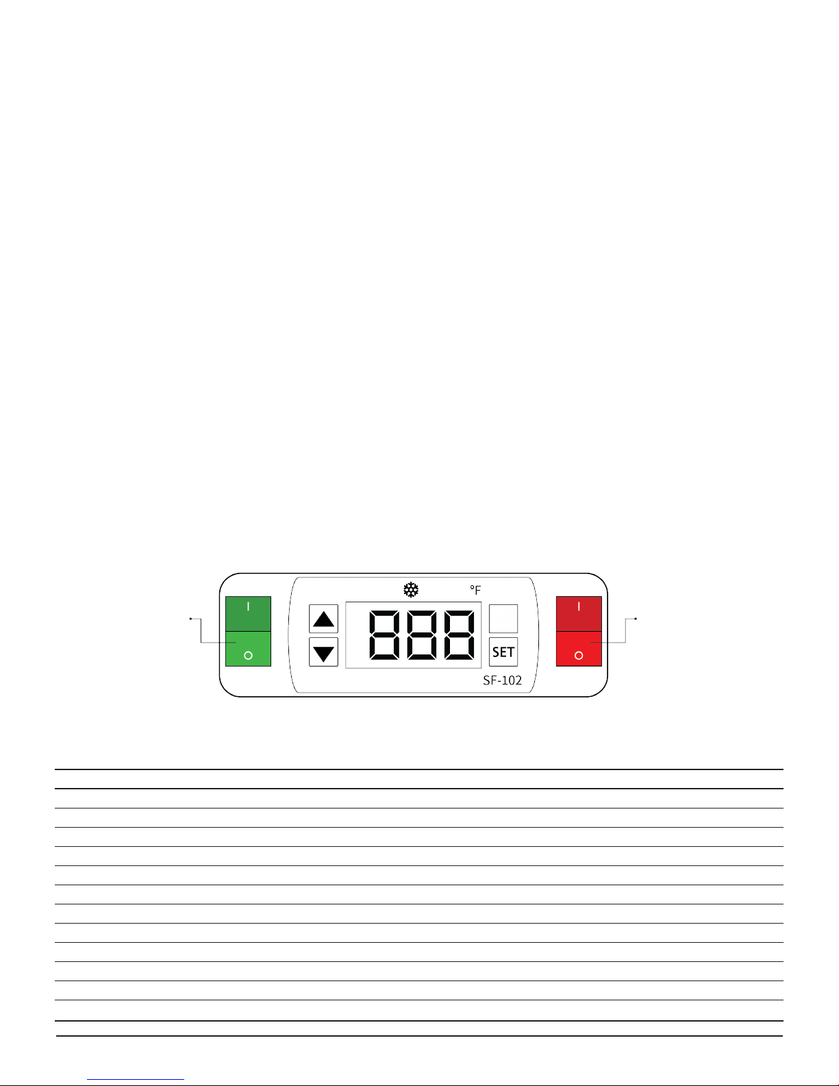
CONTROLLER SETTINGS
Please verify the make and model of the controller before going forward.
MODEL: SF-102
AN ACCESS CODE IS NEEDED TO MODIFY PARAMETERS.
PLEASE CONTACT MTL TECH SUPPORT TO RECEIVE YOUR
ACCESS CODE 1.888.685.8324
Set temperature (compressor stop temperature)
1
adjustment
• Press SET button, the set temperature is displayed.
Set the parameters
2
• Press SET button, hold for 6 seconds to enter the
parameter setup mode while E1 ashes.
• Press ▲ or ▼ to modify and store the displayed values
• Press SET button again to toggle through the
parameters (see table below).
• Press SET button to exit the adjustment and display
the unit interior temperature.
• Press ▲ or ▼ buttons, the value will be displayed and
can be modied and stored.
• If idle for 10 or more seconds, the unit interior
temperature will be displayed.
• If idle for 10 seconds the unit interior temperature will
be displayed.
Cooler
ON/OFF Switch
Lighting
ON/OFF Switch
FACTORY SETTINGS SF-102
Parameter Function Set Range Factory Settings
S Set Point 30-41 ºF / -1 to 5 ºC 26 ºF
E1 Lower set point limit 28 ºF / -45 ºC 24 ºF
E2 Raise set point limit 41 ºF / 45 ºC 32 ºF
E3 Temperature Hysteresis 1~18 ºF / 1-10 ºC 3 ºF
E4 Comp. start delay time 0 ~ 10 min 4 min
E5 Oset on room temp. -5 ~ 5 ºF / -5 to 5 ºC 0 ºF
E6 Oset on evap. temp. -5 ~ 5 ºF / -5 to 5 ºC 0 ºF
F1 Max. frost duration 1~60 min 40 min
F2 Defrost interval time 0 ~ 24 hr 3 HR
F3 Defrost termination temp. 32~68 ºF / 0~20 ºC 47 ºF
F4 Display during defrost 0=Norm. disp., 1=Last value before defrost 1 ºF
C1 Temperature unit °C , °F ºF
8
Controller Settings
1310836-07 | MAR 02 2016
Page 13
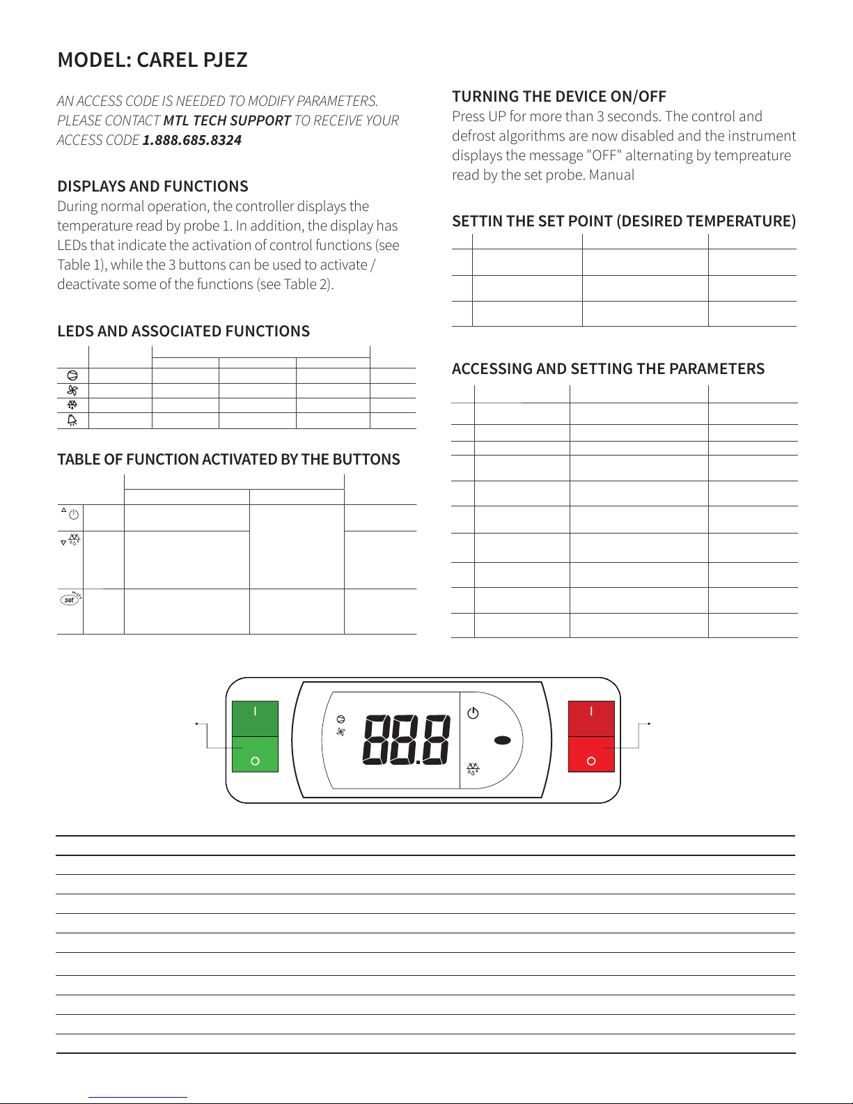
MODEL: CAREL PJEZ
AN ACCESS CODE IS NEEDED TO MODIFY PARAMETERS.
PLEASE CONTACT MTL TECH SUPPORT TO RECEIVE YOUR
ACCESS CODE 1.888.685.8324
DISPLAYS AND FUNCTIONS
During normal operation, the controller displays the
temperature read by probe 1. In addition, the display has
LEDs that indicate the activation of control functions (see
Table 1), while the 3 buttons can be used to activate /
deactivate some of the functions (see Table 2).
LEDS AND ASSOCIATED FUNCTIONS
TABLE OF FUNCTION ACTIVATED BY THE BUTTONS
TURNING THE DEVICE ON/OFF
Press UP for more than 3 seconds. The control and
defrost algorithms are now disabled and the instrument
displays the message "OFF" alternating by tempreature
read by the set probe. Manual
SETTIN THE SET POINT (DESIRED TEMPERATURE)
ACCESSING AND SETTING THE PARAMETERS
TABLE OF FUNCTIONS ACTIVATED BY THE BUTTONS
normal operation
Tab. 2
TABLE OF FUNCTIONS ACTIVATED BY THE BUTTONS
button
normal operation
start up
pressing the button alone pressed together
up
ON/OFF
more than 3 s:
toggle ON/OFF
Pressed together start/stop
continuous cycle
-
down
defrost
more than 3 s:
start/stop defrost
for 1 s display
fi rmware vers. code
set mute - 1 s.: display/set the setpoint
- more than 3 s: access parameter
setting menu (enter password ‘22’)
- mute audible alarm (buzzer)
- for 1 s RESET
current
EZY set
Tab. 2
SETTING THE SETPOINT (DESIRED TEMPERATURE)
gninaeMtceffEnoitcApetS
1
TABLE OF FUNCTIONS ACTIVATED BY THE BUTTONS
button
normal operation
start up
pressing the button alone pressed together
up
ON/OFF
more than 3 s:
toggle ON/OFF
Pressed together start/stop
continuous cycle
-
down
defrost
more than 3 s:
start/stop defrost
for 1 s display
fi rmware vers. code
set mute - 1 s.: display/set the setpoint
- more than 3 s: access parameter
setting menu (enter password ‘22’)
- mute audible alarm (buzzer)
- for 1 s RESET
current
EZY set
Tab. 2
SETTING THE SETPOINT (DESIRED TEMPERATURE)
gninaeMtceffEnoitcApetS
1
Keep SET button pressed for 2 s
After 1 sec currently setpoint value will
fl ash on display
It’s regulation setpoint
currently active
2 Press UP or DOWN buttons Setpoint value will chang
3 Press SE T button Controller will visualize temperature
read by probes again
Setpoint is modifi ed and
saved
Tab. 3
ACCESSING AND SETTING THE PARAMETERS
Set desired value
TABLE OF FUNCTIONS ACTIVATED BY THE BUTTONS
button
normal operation
start up
pressing the button alone pressed together
up
ON/OFF
more than 3 s:
toggle ON/OFF
Pressed together start/stop
continuous cycle
-
down
defrost
more than 3 s:
start/stop defrost
for 1 s display
fi rmware vers. code
set mute - 1 s.: display/set the setpoint
- more than 3 s: access parameter
setting menu (enter password ‘22’)
- mute audible alarm (buzzer)
- for 1 s RESET
current
EZY set
Tab. 2
SETTING THE SETPOINT (DESIRED TEMPERATURE)
gninaeMtceffEnoitcApetS
1
Keep SET button pressed for 2 s
After 1 sec currently setpoint value will
fl ash on display
It’s regulation setpoint
currently active
2 Press UP or DOWN buttons Setpoint value will chang
3 Press SET button Controller will visualize temperature
read by probes again
Setpoint is modifi ed and
saved
Tab. 3
ACCESSING AND SETTING THE PARAMETERS
gninaeMtceffEnoitcApetS
1 Keep SET button pressed
for 3 s
After 3 sec display will visualize “ PS ” Password is requested
2 Press SET button again Display will visualize “ 0 ” blinking
3 Press UP or DOWN button Visualized value on display will change 22 ”
4 Press SET button After 5 sec the fi rst parameter, “ /5”, will be
visualized on display
It’s the name of the fi rst
parameter
5 Press UP or DOWN button Parameter list will be scrolled on display
(refer to Table of parameters)
Select desired parameter
6 Press SET button Display will visualize value of the selected
parameter
It’s the currently parameter
value
7 Press UP or DOWN button Parameter value visualized on display will
change
Set desired value
8 Press SET button Display will visualize parameter name
again
Attention : parameters
updating is not yet active
9 Repeat steps 5, 6, 7 and 8
for all desired parameters
10 Keep SET button
Controller will visualize temperature read
Attention: now parame-
Insert password “
Set desired value
Keep SET button pressed for 2 s
2 Press UP or DOWN buttons Setpoint value will chang
After 1 sec currently setpoint value will
fl ash on display
It’s regulation setpoint
currently active
Set desired value
icon function normal operation
compressor
ON OFF blink
on off request ON
fan on off request ON
defrost on off request ON
alarm all no alarm - ON
button
up
ON/OFF
down
defrost
pressing the button alone pressed together
more than 3 s:
toggle ON/OFF
more than 3 s:
start/stop defrost
Pressed together start/stop
continuous cycle
set mute - 1 s.: display/set the setpoint
- more than 3 s: access parameter
setting menu (enter password ‘22’)
- mute audible alarm (buzzer)
- for 1 s RESET
FACTORY SETTINGS CAREL
Parameter Function Set Range Factory Settings
Cooler
ON/OFF Switch
PS Password 0 - 200 22
-
/5 Select °C / °F 0 - 1 1 ºF
r1 Minimum set point allowed to the user -50.0 - r2 24 ºF
r2 Maximum set point allowed to the user r1 - 200 32 ºF
rd Control dierential (hysteresis) 0.0 - 19.0 3 ºF
c2 Min. compressor o time 0 - 100 4 min
d1 Interval between two defrosts 0 - 199 3 hr
dt End defrost temperature 50.0 - 130.0 47 ºF
dP Max. or eective defrost duration 1 - 199 40 min
1310836-07 | MAR 02 2016
Set point 24º - 32º F 26 ºF
3 Press SET button Controller will visualize temperature
start up
1 Keep SET button pressed
for 3 s
Tab. 1
start up
-
for 1 s display
fi rmware vers. code
current
EZY set
2 Press S ET button again Display will visualize “ 0” blinking
3 Press U P or DOWN button Visualized value on display will change 22 ”
4 Press S ET button After 5 sec the fi rst parameter, “ /5”, will be
5 Press U P or DOWN button Parameter list will be scrolled on display
6 Press S ET button Display will visualize value of the selected
7 Press U P or DOWN button Parameter value visualized on display will
8 Press S ET button Display will visualize parameter name
9 Repeat steps 5, 6, 7 and 8
for all desired parameters
10 Keep SET button
pressed for 5 s
SET
Controller Settings
read by probes again
After 3 sec display will visualize “ PS” Password is requested
visualized on display
(refer to Table of parameters)
parameter
change
again
Controller will visualize temperature read
by probes again
Lighting
ON/OFF Switch
Setpoint is modifi ed and
saved
Insert password “
It’s the name of the fi rst
parameter
Select desired parameter
It’s the currently parameter
value
Set desired value
Attention : parameters
updating is not yet active
Attention: now parameters updating will be active
gninaeMtceffEnoitcApetS
Tab. 3
Tab. 4
9
 Loading...