

Page 1

SWIMMING POOL HEAT PUMP UNIT
Installation & Instruction Manual
Page 2

1. Preface
2. Specifications
2.1 Performance Data of Swimming Pool Heat Pump Unit
2.2 Dimensions for Swimming Pool Heat Pump Unit
3. Installation and Connection
3.1
3.2
3.3 How Close to Your Pool?
3.4 Swimming Pool Heat Pumps Plumbing
3.5 Swimming Pool Heat Pumps Electrical Wiring
3.6 Initial Start-up of the Unit
4. Operation and Use
4.1
4.2
4.3
4.4
5. Maintenance and Inspection
6.Appendix
Page 3

CONTENTS
1. Preface
2. Specifications
2.1 Performance Data of Swimming Pool Heat Pump Unit
2.2 Dimensions for Swimming Pool Heat Pump Unit
3. Installation and Connection
3.1
3.2
3.3 How Close to Your Pool?
3.4 Swimming Pool Heat Pumps Plumbing
3.5 Swimming Pool Heat Pumps Electrical Wiring
3.6 Initial Start-up of the Unit
4. Operation and Use
4.1
4.2
4.3
4.4
5. Maintenance and Inspection
6.Appendix
Installation illustration
Swimming Pool Heat Pumps Location
Color screen wire controller interface introduction
Color screen wire controller function introduction
Parameter list and breakdown table
Interface drawin
6.2 Cable specification
6.1 Caution & Warning
6.3 Explosive view of the unit
1
2
2
4
6
6
7
7
8
9
9
10
10
11
18
20
22
23
23
24
25
Page 4

2.SPECIFICATION
2.1 Performance data of Swimming Pool Heat Pump Unit
Rated Heating: Outdoor air temp: 27 , Inlet water temp:26 /28
1. PREFACE
In order to provide our cus tomers with quality, reliability and versatility, this product has
been made to strict produ ction standards. This manual includes all the necessary
information about ins tallation, debugging, discharging and maintenance. Please read this
manual carefully before you open or maintain the unit. The manufacture of this product will
not be held responsible if someone is injured or the unit is damaged, as a result of
improper installation, debugging, or unnecessary main tenance. It is vital that the
instructions within this manual are adhered to at all times. The unit must be installed by
qualified personnel.
The unit can only be repaired by qualified installer centre , personnel or an authorised
dealer.
Maintenance and operation must be carried out according to the recommended time and
frequency, as stated in this manual.
Use genuine standard spare parts only.
Failure to comply with these recommendations will invalid ate the warranty.
Swimming Pool Heat Pump Unit heats the swimming pool water and keeps the temperature
constant. For split type unit, The indoor uni t can be Discretely hidden or semi-hidden to
suit a luxury house.
Our heat pump has followi ng characteristics:
1 Durable
The heat exchanger is made of PVC & Titanium tube wh ich can withstand prolonged
exposure to swimming pool water.
2 Installation flexibility
The unit can be installed outdoors or in doors.
3 Quiet operation
The unit comprises an efficient rotary/ scroll compres sor and a low-noise fan motor,
which guarantees its qu iet operation.
4 Advanced contro lling
The unit includes micro-computer contro lling, allowing all operation para meters to be
set. Operation status can be dis played on the LCD wire controller. Remo te controller can be
chosen as future option.
1
Page 5

2
2.SPECIFICATION
2.1 Performance data of Swimming Pool Heat Pump Unit
*** REFRIGERANT : R410A
Rated Heating: Outdoor air temp: 27 , Inlet water temp:26 /28
℃/24.3℃ ℃ ℃
UNIT
Nominal Heating Power
Input By 50Hz
Range
Nominal Running Current
Input By 50Hz
Range
Power Supply
Compressor Quantity
Compressor
Fan Quantity
Fan Power Input
Fan Rotate Speed
Fan Direction
Noise
Water Connection
Water Flow Volume
Water Pressure Drop(max)
Unit Net Dimensions(L/W/H)
Unit Ship Dimensions(L/W/H)
Net Weight
Shipping Weight
kW
Btu/h
kW
Btu/h
kW
A
W
RPM
dB(A)
mm
3
m /h
kPa
mm
mm
kg
kg
Nominal Heating Capacity
By 50Hz
Range
KW
A
OASIS Ci 10
7.1
24140
2.85~12.0
9690~40800
0.21~2.12
0.9~9.2
230V~/50Hz
1
rotary
1
100
400-800
horizontal
42-52
40
4.2
4.5
1051×410×76 7
1130×470×790
59
69
0.99
4.3
OASIS Ci 13
9.4
31960
3.8~17.0
12920~57800
0.30~3.02
1.3~13.1
230V~/50Hz
1
rotary
1
120
500-750
horizontal
44-53
40
5.3
5.0
1163×447×868
1210×510×88 0
77
95
1.30
5.6
Page 6

2.2 The dimensions for Swimming Pool Heat Pump Unit
OASIS Ci 10
2.SPECIFICATION
3
2.SPECIFICATION
2.1 Performance data of Swimming Pool Heat Pump Unit
*** REFRIGERANT : R410A
Rated Heating: Outdoor air temp: 27 , Inlet water temp:26 /28
℃/24.3℃ ℃ ℃
UNIT
Nominal Heating Power
Input By 50Hz
Range
Nominal Running Current
Input By 50Hz
Range
Power Supply
Compressor Quantity
Compressor
Fan Quantity
Fan Power Input
Fan Rotate Speed
Fan Direction
Noise
Water Connection
Water Flow Volume
Water Pressure Drop(max)
Unit Net Dimensions(L/W/H)
Unit Ship Dimensions(L/W/H)
Net Weight
Shipping Weight
kW
Btu/h
kW
Btu/h
kW
A
W
RPM
dB(A)
mm
3
m /h
kPa
mm
mm
kg
kg
Nominal Heating Capacity
By 50Hz
Range
KW
A
OASIS Ci 17
11.5
39100
4.6~19.5
15640~66300
0.37~3.94
1.6~17.1
230V~/50Hz
1
rotary
1
120
500-900
horizontal
45-56
40
6.6
6
1163×447×868
1210×510×880
82
95
1.72
7.5
OASIS Ci 21
14.3
48620
5.7~24.2
19380~82280
0.46~4.8
2.0~20.9
230V~/50Hz
1
rotary
2
200
400-800
horizontal
46-57
40
8.6
11
1163×470×1275
1210×495×1300
110
125
2.1
9.1
OASIS Ci 25T
17.2
58480
6.7~28.3
22780~96220
0.54~5.57
1.34~9.18
380V/3N~/50Hz
1
rotary
2
200
400-800
horizontal
48-58
40
10
15
1163×470×1275
1210×495×1300
113
131
2.5
4.48
Page 7

2.2 The dimensions for Swimming Pool Heat Pump Unit
OASIS Ci 10
unit:mm
unit:mm
Wat er inle t
Φ40
Wat er outl et
Φ40
3
50
100
10
51
767
435
630
4
10
3
96
447
430
868
1163
470
815
Wat er inle t
Φ40
Wat er outl et
Φ40
A
100
2.SPECIFICATION
4
OASI S Ci 13
Mode l
A
OASI S Ci 17
400 470
Page 8

Installation items:
The factory only provides the main uni t and the w ater unit; the other items in the illustration
are necessary spare parts for the water system ,that provided by users or the ins taller.
3.1 Installation illustration
Attention:
Please follow these ste ps when using for the first time
1.Open valve and charge water.
2.Make sure that the pump a nd the water-in pipe have been filled with wate r.
3.Close the valve and sta rt the unit.
ATTN: It is necessary that the water-in pipe is hi gher than the pool surface.
3.INSTALLATION AND CONNECTION
The schematic diagram is for referen ce only. Please check the water inlet/outlet label on the
heat pump while plumbing installation.
2.SPECIFICATION
5
2.2 The dimensions for Swimming Pool Heat Pump Unit
Wat er inle t
Φ40
Wat er outl et
Φ40
470
100
OASIS Ci 21/OASIS Ci 25
unit:mm
1163
1275
790
430
470
447
Page 9

6
Installation items:
The factory only provides the main uni t and the w ater unit; the other items in the illustration
are necessary spare parts for the water system ,that provided by users or the ins taller.
3.1 Installation illustration
Attention:
Please follow these ste ps when using for the first time
1.Open valve and charge water.
2.Make sure that the pump a nd the water-in pipe have been filled with wate r.
3.Close the valve and sta rt the unit.
ATTN: It is necessary that the water-in pipe is hi gher than the pool surface.
3.INSTALLATION AND CONNECTION
Chlorinator cell
Water outlet
Pool
Valve
Water supply
Water inlet
Water pump
Sand filter
(or other type filter)
The schematic diagram is for referen ce only. Please check the water inlet/outlet label on the
heat pump while plumbing installation.
Page 10

3.INSTALLATION AND CONNECTION
3.4 Swimming Pool Heat Pumps Plumbing
Location: Connect the u nit in the pool pump discharge (return) line downstream of all filter
and pool pumps, and upstream of any chlorinators, ozonators or chemi cal pumps.
Standard model have slip glue fittings which accept 32mm or 50 mm PVC pipe for
connection to the pool or spa filtration piping. By using a 50 NB to 40NB you can plumb 40NB
Give serious consideration to adding a quick coupler fitting at the unit inlet and outlet to allow
easy draining of unit for winterizing and to provide easier access should servicing be
required.
Condensation: Since the Heat pump cools down the air about 4 -5℃, water may condense on
the fins of the horseshoe s haped evaporator. If the relative humidity i s very high, this could
be as much as several litre s an hour. The wat er will run down the fins into the basepan and
drain out through the barbed plastic condensation drain fitting on the side of the basepan.
This fitting is designed to accept 20mm clear vinyl tubing which can be pushed on by hand
and run to a suitable drain. It is easy to mistake the condensation for a water leak inside the
unit.
NB: A quick way to verify that the water is condensation is to shut off the unit and keep the
pool pump runnin g. If the water stops running out of the basepan, it is condensation. AN
EVEN QUICKER WAY IS to TEST THE DRAIN WATER FOR CHLORINE - if the is no chlori ne
present, then it's condensation.
The Swimming Pool Heat Pumps exclusive rated flow titanium heat exchanger requires no
special plumbi ng arrangements except bypass(pl ease set the flow rate according to the
nameplate). The water pressure drop is less than 10kPa at max. Flow rate. Since there is no
residual heat or flame Temperatures, The unit does not need copper heat sink piping. PVC
pipe can be run straight into the unit.
7
3.INSTALLATION AND CONNECTION
The unit will perform wel l in any outdoor location provided that the fol lowing three factors are
presented:
1. Fresh Air - 2. Electricity - 3. Pool filter piping
The unit may be installed v irtually anywhere outdoors. For indoor pools please consult the
supplier. Unlik e a gas heater, it has no draft or pilot light problem in a windy area.
DO NOT place the unit in an enclosed area wi th a limited air volume, where the units
discharge air wi ll be re-circulated.
DO NOT place the unit to shrubs which can bl ock air inlet. These locations deny the unit of a
continuous source of fr esh air which reduces it efficiency and may prevent adequate heat
delivery.
3.2 Swimming Pool Heat Pumps Location
Normally, the pool heat pump is install ed within 7.5 metres of the pool. The longer the
distance from the pool, the greater the heat loss from the piping. For the most part ,the pi ping
is buried. Therefore, the heat loss is m inimal for runs of up to15 meters(15 meters to and from
the pump = 30 meters total), unless the ground is wet or the water table is high. A very rough
estimate of heat loss per 30 meters is 0.6 kW-hou r,(2000BTU) for every 5 ℃ difference in
temperature between the pool water and the ground surrounding the pipe, which translates to
about 3% to 5% increase in run time.
3.3 How Close To Your Pool?
Air inlet
Air outlet
3
00mm
700mm
300mm
500mm
700mm
Page 11

3.INSTALLATION AND CONNECTION
8
3.4 Swimming Pool Heat Pumps Plumbing
Location: Connect the u nit in the pool pump discharge (return) line downstream of all filter
and pool pumps, and upstream of any chlorinators, ozonators or chemi cal pumps.
Standard model have slip glue fittings which accept 32mm or 50 mm PVC pipe for
connection to the pool or spa filtration piping. By using a 50 NB to 40NB you can plumb 40NB
Give serious consideration to adding a quick coupler fitting at the unit inlet and outlet to allow
easy draining of unit for winterizing and to provide easier access should servicing be
required.
Condensation: Since the Heat pump cools down the air about 4 -5℃, water may condense on
the fins of the horseshoe s haped evaporator. If the relative humidity i s very high, this could
be as much as several litre s an hour. The wat er will run down the fins into the basepan and
drain out through the barbed plastic condensation drain fitting on the side of the basepan.
This fitting is designed to accept 20mm clear vinyl tubing which can be pushed on by hand
and run to a suitable drain. It is easy to mistake the condensation for a water leak inside the
unit.
NB: A quick way to verify that the water is condensation is to shut off the unit and keep the
pool pump runnin g. If the water stops running out of the basepan, it is condensation. AN
EVEN QUICKER WAY IS to TEST THE DRAIN WATER FOR CHLORINE - if the is no chlori ne
present, then it's condensation.
To pool
From pump
PVC COUPLER
RECOMMENDED(Provi ded)
CONDENSATION
DRAIN
BARB FTG
The Swimming Pool Heat Pumps exclusive rated flow titanium heat exchanger requires no
special plumbi ng arrangements except bypass(pl ease set the flow rate according to the
nameplate). The water pressure drop is less than 10kPa at max. Flow rate. Since there is no
residual heat or flame Temperatures, The unit does not need copper heat sink piping. PVC
pipe can be run straight into the unit.
Page 12

4.OPERATION AND USE
3.5 Swimming Pool Heat Pumps Electrical Wiring
NOTE: Although the unit heat exch anger is electrically isolated from the rest of the unit, it
simply prevents the flo w of electricity to or from the pool water. Grounding the unit is still
required to protect you a gainst short circuits inside the unit. Bonding is also required.
3.INSTALLATION AND CONNECTION
3.6 Initial startup of the Unit
NOTE- In order for the unit to heat the pool or spa, the filter pump must be running to
circulate water throu gh the heat exchanger.
Start up Procedure - After i nstallation is completed, you should follow these steps:
1. Turn on your filter pump. Check for water leaks and verify flow to and from the pool.
2. Turn on the electrical power supply to the unit, then press the key ON/OFF of wire
controller, It should start in se veral seconds.
3. After running a few minutes make s ure the air leaving the top(side) of the unit is
cooler(Between 5-10 ℃)
4. With the unit operating turn the filte r pump off. The unit should also turn o ff automatically,
5. Allow the unit and pool pump to run 24 hours per day until desired pool water emperature is
reached. When the water -in temperature reach setting, The unit just shuts off. The unit will
now automatically res tart (as long as your pool pump is running)when the pool temperature
drops more than 2℃below set temperature.
Time Delay- The unit is equipped with a 3 minute built-in solid state restart delay included to
protect control circu it components and to eliminate restart cycling and contactor chatter.
This time delay will auto matically restart the unit approximately 3 minutes after each control
circuit interruptio n. Even a brief power interruption will activ ate the solid state 3 minute
restart delay and prevent the unit from starting until the 5 minute countdown i s completed.
Power interruptions during the delay period will have no effect on the 3 minute countdown.
The unit has a separate molded-in junction box with a standard electrical conduit nipple
already in place . Just remove the screws and the front panel, feed your su pply lines in
through the conduit nip ple and wire-nut the electric supply wires to the three connections
already in the junction box (four connections if three phase). To complete electric al hookup,
connect Heat Pump by electrical conduit, UF cable or other suitable means as specified (as
permitted by local electrical authorities) to a dedicated AC power supply branch circuit
equipped with the proper circuit breaker, disconnect or time delay fuse protection.
Disconnect - A disconnect means (circuit breaker , fused or un-fused switch ) should be
located within sight of and readily accessible from the unit, This is common practice on
commercial and r esidential air conditioners and heat pumps. It prevents remotely-energizing
unattended equipment and permits turning off power at the unit while the unit is being
serviced.
9
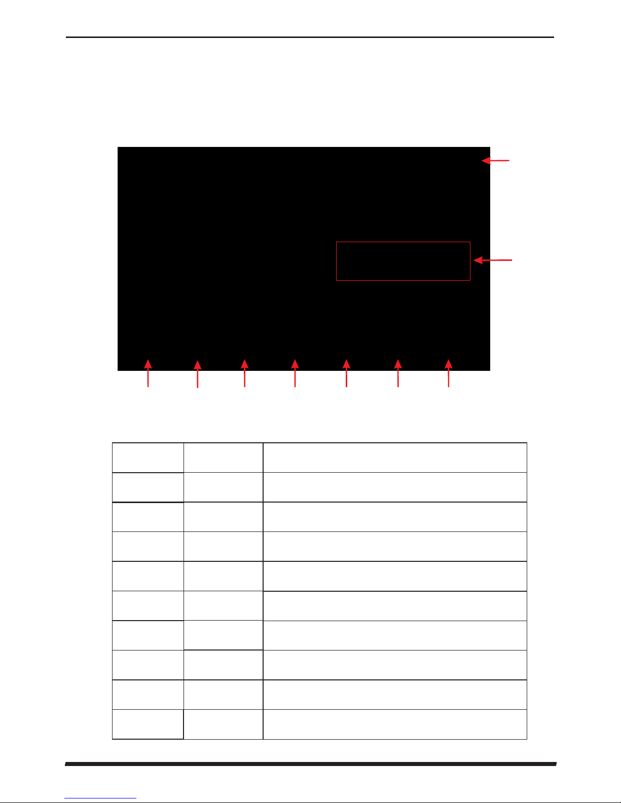
4.1 Color screen wire controller interface introduction
Page 13
4.OPERATION AND USE
10
NO.
Name
ON/OFF
Parameter
CLOCK
Fault display
LOCK
Water
Inlet Temp.
The button function
Press to start /shut off the unit
Click this button to view the unit state and the
parameter
Press to set the clock, the timer on or timer off.
When the timer was starting,the button is green
Click to turn on/off silent function and to set
timing Low speed functi on.
①
②
③
④
⑤
⑥
⑦
⑧
Click to view fault history
Temp. curve
Silent setting
⑨
Click to lock the screen ,In put "22" to unlock
the screen by press the "lock button"
4.1 Color screen wire controller interface introduction
(1) Main interface
(2) Button Description
Click to enter mode setting and th e target temp.
Setting interface
MODE
Click to view the temp. and power curve
② ③ ④ ⑤ ⑥①
⑨
⑧
⑦
Click to enter mode setting and th e target temp.
Setting interface
Page 14
11 12
4.OPERATION AND USE
4.OPERATION AND USE
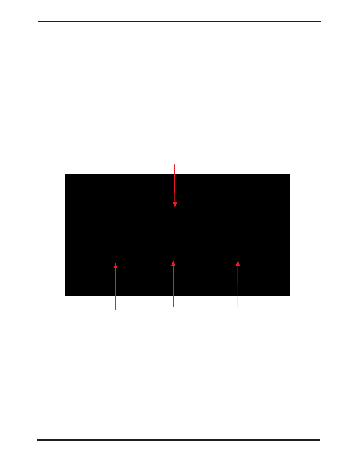
4.2 Color screen wire controller function introduction
(2) Mode switch and target temperature Setting
Click the refrigeration mode button , automatic mode button or
heating mode button then you can select the corresponding mode.
① ②
③
Note: when the unit is designed for single automatic mode or single
thermal mode,
the mode can not be switched.
(1) Booting and shutdown
In shutdown status, click then the unit will be booted ①
In booting status, click then the unit will be shut down.①
As shown in figure 1.1:
Click the temperature set
button , you can set the target temperature.
④
2.2 1 Mode switch
2-2 Target temp. setting
①
④
③
②
In the main interface, click mode button or inlet water temperature setting
button, interface displays as follows:
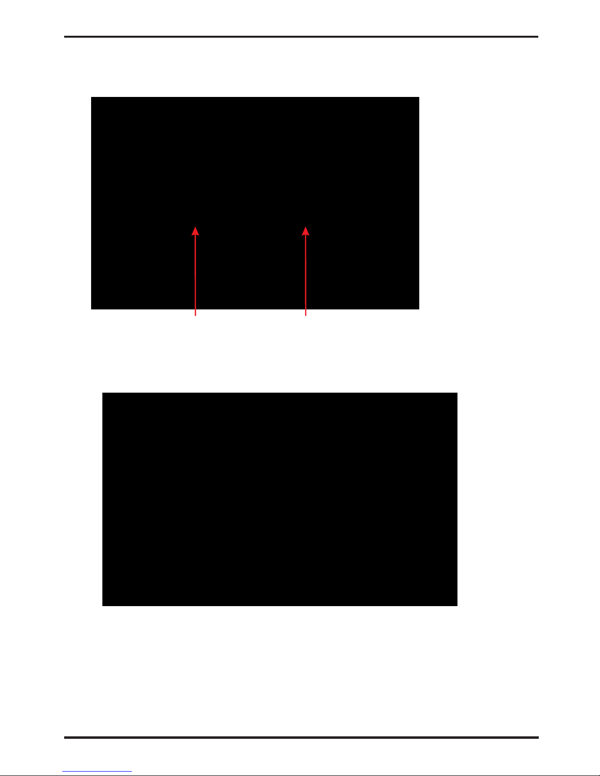
(3) Clock setting
Page 15
4.OPERATION AND USE
Click the value to set time directly, the click confirm button to save
the
Settings.
In the main interface, click on the clock Settings button,
interface displays as follows:
(3) Clock setting
Click on the time Settings button ,
interface displays as follows:
①
Note: if the input format is not correct, the wrong time will be saved by
clicking confirm button.
For example: setup time: the 30-11-2016 16:00:00, input 30 11 16 16 00 00 ,
the time change then click confirm button.
3-1The operation of time setting
① ②
Page 16
13
4.OPERATION AND USE
4.OPERATION AND USE
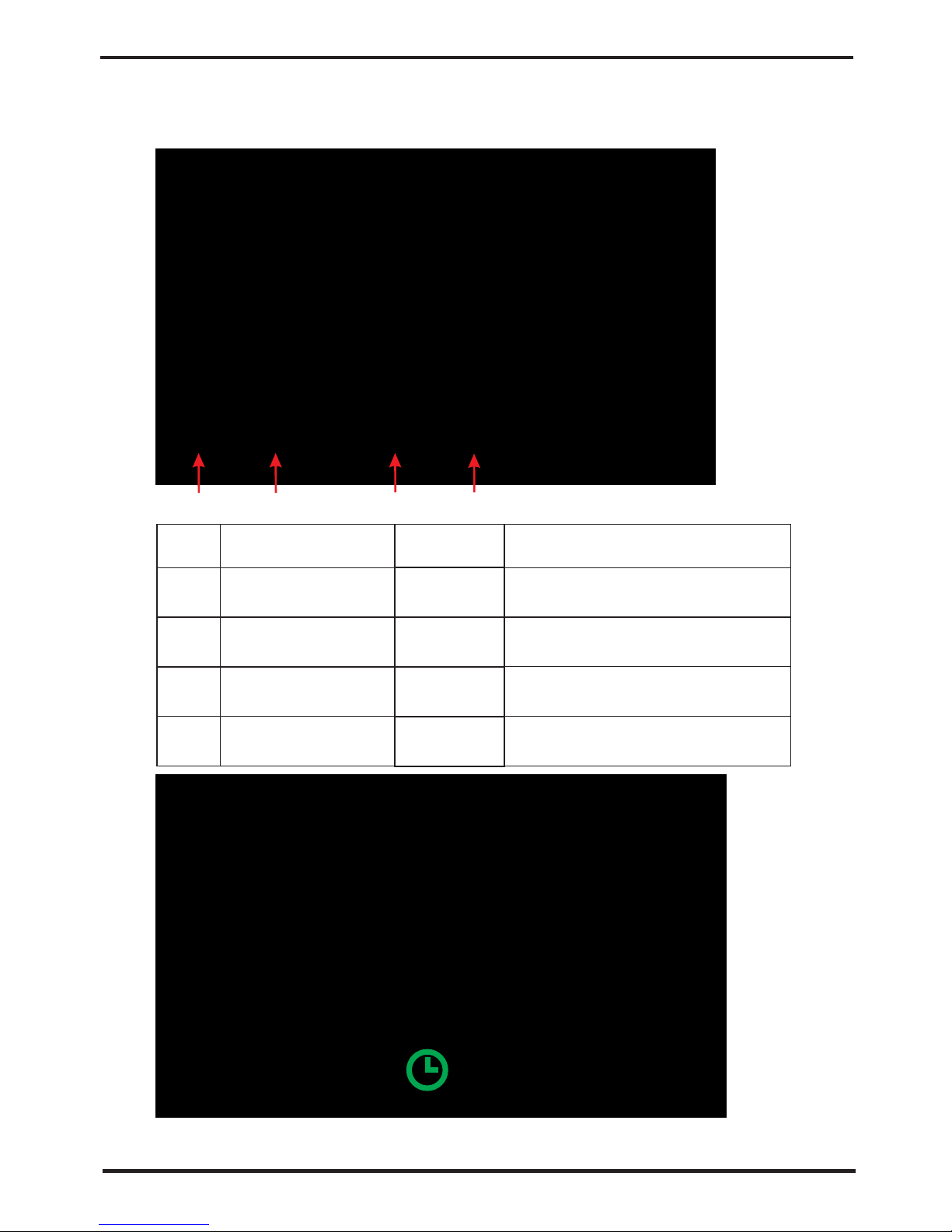
3-2 The operation of timing setting
Click the timing set button timing setinterface.② to enter
Button function
Click this button to start or end
timing start setting functio n
Start: green
End: gray
Open: red
End: gray
Click this button to start or end
t i m i n g end s etti n g funct ion
Button color
Timing starbtu tton
Timing on setting
Timing end button
Timing off setting
Click to set end time of the timing
NO.
①
②
③
④
Click to set start time of the timing
Name
When the timer was starting,the clock button is green in the main interface
①
② ③ ④
Page 17
14
4.OPERATION AND USE
②
(4) Silent setting and silent timing setting
as follows:
Click the silent setting button ,and the interface displays
4-1 The silent button
①
Click the silent button , the unit will enter the silent mode,
and interface displays as follows:
①
Click the silent button again, to exit the silent mode.①
Page 18
15
4.OPERATION AND USE 4.OPERATION AND USE
4-2 Timing silent function setting
Start time and end time setting value must be among the range of
and se ttin g v alue can be prec ise to hour digit.
0:00-23:00,
For example above, click "ON"to use timing silent,
the unit will start the silent at 0:00 points and end at 4:00;
click "OFF" to unuse the timing silent, but if the unit
is in timing silent mode, it will exit silent timing immediately.
Click timing silent button , and interface displays as follows:②
Colur
Use:green
Unused:gray
Used: red
Unused:gray
Function
Click to use or unuse timing
on function
Click to use or unuse timing
off function
Click this button to set the timin g
silent start time
Click this button to set the timin g
silent end time
Timing silent on
Timing silent off
Timing silent start
t i m e
Timing silent end
t i m e
①
②
NO.
③
④
Name
①
③
④
②
(5) History of the fault
Page 19
16
(5) History of the fault
In the main interface click fault display key, interface displays as follows:
If no failure, main interface displays static " "
After troubleshooting, if you do not check the failure record,
the main interface will display static " "; if you check the
failurerecord, the main interface will displays static " ";
Failure record is in reverse order,according to the happening time.
Press the "Clean" key,you can delete the fault record.
When fault occurs,the fault icon will flash between the " " " ",
the failure interface will record time, code, name of the fault.
Fault time
day - month - year
hour:min
The fault name
Fault code
Page 20

17
4.OPERATION AND USE
4.OPERATION AND USE
(6) Temperature curve
In the main interface, click the curve display button,
interface displays as follows:
6-2 The average power curve
2.6.1 Temperature recording curve is as follows:
Temperature curve automatically updates every one hour,
and the curve record can be stored for 60 days;
Start from the latest curve saved time, if power is off and
curve data collecting time is less than one hour,
the data
in this period will not be saved;
4.3 Parameter list and breakdown table
Low te mp era ture prot ectio n
Stan dby
Norm al boot
Amib ent Temp. Sen sor F au lt
Outl et Temp. Sens or Faul t
Coil Temp. S ensor F ault
Seco ndary A nti- freez ing P rot.
Anti -free zing Pr ot
Suct ion Temp. Sen sor Fau lt
Low Pr essur e Prot.
Flow S witch P rot.
Inle t and out let tem p. too bi g
Disc harge Temp. S ens or
Faul t
High P ressu re Prot .
Exha ust Air ov er Temp Prot.
Comp . Overc urren t Prot.
Comm unica tion Fa ult
Prim ary Anti -free zing Pr ot.
Anti fr eeze Temp. Sens or F ault
Wat erway An ti-fr eezin g Pro t.
EC fan f eedba ck Faul t
Inle t Temp . Senso r Fault
Pres sure se nsor Fa ult
Fan Mo tor1 Fa ult
Page 21
18
4.OPERATION AND USE
4.3 Parameter list and breakdown table
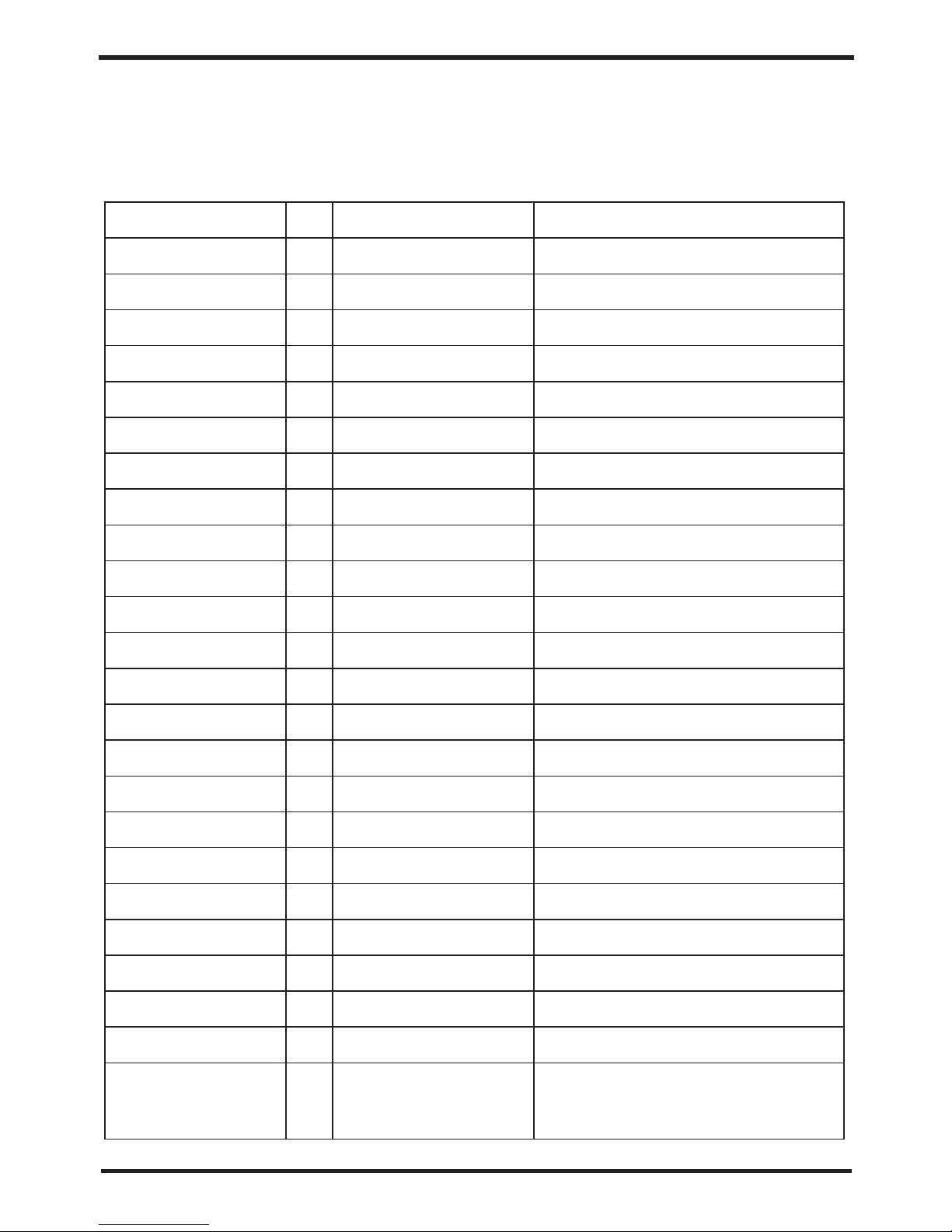
(1) Electronic control fault table
Low te mp era ture prot ectio n
Can be judged according to the remote controller failure code and
troubleshooting
Prot ect/f ault
Stan dby
Norm al boot
Amib ent Temp. Sen sor F au lt
Outl et Temp. Sens or Faul t
Coil Temp. S ensor F ault
Seco ndary A nti- freez ing P rot.
Anti -free zing Pr ot
Suct ion Temp. Sen sor Fau lt
Low Pr essur e Prot.
Flow S witch P rot.
Inle t and out let tem p. too bi g
Disc harge Temp. S ens or
Faul t
High P ressu re Prot .
Exha ust Air ov er Temp Prot.
Comp . Overc urren t Prot.
Comm unica tion Fa ult
Prim ary Anti -free zing Pr ot.
Faul t
disp lay
Non
Non
P01
P02
P04
P05
P07
E02
E07
E03
E29
E06
P081
Non
E051
E08
E19
E01
P082
Reas on Elim inati on meth ods
Anti fr eeze Temp. Sens or F ault
Wat erway An ti-fr eezin g Pro t.
EC fan f eedba ck Faul t
P09
E05
F051
Chec k the wir e conne ction b etw ee n
remo te wire c ontro ller an d mai n bo ard
Chec k wheth er the sy stem of t he comp resso r
runn ing nor mal ly
Chec k wheth er the sy stem of t he comp resso r
runn ing nor mal ly
Chec k the pip e water f low a nd w het her
wate r syste m is jamm ed or not
Chec k the pip e water f low a nd w het her
wate r syste m is jamm ed or not
Chec k the pip e water f low a nd w ate r pump
Chec k or chan ge the te mp. Sen sor
Chec k or chan ge the te mp. Sen sor
Chec k or chan ge the te mp. Sen sor
Chec k or chan ge the te mp. Sen sor
Chec k or chan ge the te mp. Sen sor
Chec k the pre ssure s witch a nd co ld circ uit
Chec k or chan ge the te mp. Sen sor
Chec k the pre ssure s witch a nd co ld circ uit
chec k and rep lace th is temp s ens or
Chec k wheth er fan mo tor i s br oke n or lock ed
or not
Inle t Temp . Senso r Fault
PP
Pres sure se nsor Fa ult
The te mp. Sen sor is br oken
or sho rt circ uit
The te mp. Sen sor is br oken
or sho rt circ uit
The te mp. Sen sor is br oken
or sho rt circ uit
The te mp. Sen sor is br oken
or sho rt circ uit
The en viron ment te mp. is lo w
The am bient t emp. Is l ow
Wat er flow i s not eno ugh
and lo w differe ntial p res su re
Wat er flow i s not eno ugh
The te mp. Sen sor is br oken
or sho rt circ uit
Low pr essur e1 prot ectio n
No wat er/li ttle wa ter in
wate r syste m
The te mp. Sen sor is br oken
or sho rt circ uit
The hi gh-pr eesur e switc h is
brok en
The co mpres sor is ov erloa d
The am bient t emp. Is l ow
Comm unica t ion fai lure be twe en
wire c ontro ller an d mainb oar d
The co mpres sor is ov erloa d
anti freez e temp se nsor is
brok en or sho rt circ uited
wate r temp. or ambi ent tem p.
is too l ow
There is something wrong with fan
motor and fan motor stops running
The pr essur e Senso r is brok en
F031
Fan Mo tor1 Fa ult
1. Mot or is in lo cked- rotor s tate
2.Th e wire co nnect ion b et wee n
DC-f an moto r modul e and fan
moto r is in bad c ontac t
1.Ch ange a ne w fan mot or
2.Ch eck the w ire con nec ti on an d make su re
they a re in goo d conta ct
Chec k or chan ge the pr essur e Sen so r
or pre ssure
Page 22
4.4 Interface drawin
19
4.OPERATION AND USE
4.OPERATION AND USE
Drv1 MOP alarm
Inverter offline
IPM pr otection
Comp. Driver Failure
DC Fan Fault
IPM Overcurrent
Inv. DC Overvoltage
Inv. DC Lessvoltage
Inv. Input Lessvolt.
Inv. Input Overvolt.
Inv. Sampling Volt.
Comm. Err DSP-PFC
Input Over Cur.
PFC fault
IPM Over heating
Weak Magnetic Warn
Inv. Input Out Phase
IPM Sa mpling Cur.
Inv. Temp. Pr obe Fail
Inverter Overheating
Inv. Overheating Warn
Comp. OverCur. Warn
Input Over Cur. Warn
EEPROM Error Warn
Prot ectio n/fau lt
Frequency conversion board fault table:
F01
F02
F03
F04
F05
F06
F07
F08
F09
F10
F11
F12
F26
F27
F15
F16
F17
F18
F19
F20
F22
F23
F24
F25
MOP driv e alarm
Freq uency c onver sio n bo ard a nd main
boar d commu nicat ion f ai lur e
IPM mo dular p rotec tion
Lack o f phase , step or d riv e ha rdw are
dama g
Moto r curre nt feed bac k op en ci rcuit o r
shor t circu it
IPM In put cur rent is l arge
DC bus v oltag e>Dc bu s ove r- vol tage
prot ectio n value
DC bus v oltag e<Dc bu s ove r- vol tage
prot ectio n value
The in put v oltag e is lo w, causi ng the
inpu t
curr ent i s high
The in put v oltag e is to o high, m ore than
outa ge pr otect ion c urren t RMS
The in put v oltag e sam pling f ault
DSP and PFC con nect fa ult
The equip men t load is t oo large
The PF C cir cuit pr ote ction
The IP M mod ule is ov erh eat
Comp res sor mag net ic forc e is no t
enou gh
Reco very af ter the 1 50s
Chec k the com munic ation c onn ec tio n
Reco very af ter the 1 50s
Chec k the mea surin g vol ta ge ch eck
requ ency co nvers ion boa rd ha rdwar e
Chec k wheth er curr ent r et urn w ires
conn ected m otor
Chec k and adj ust the c urr en t
meas ureme nt
Chec k the inp ut volt age mea sur em ent
Chec k the inp ut volt age mea sur em ent
Chec k the inp ut volt age mea sur em ent
Chec k the inp ut volt age mea sur em ent
Chec k and adj ust the c urren t
meas ureme nt
Chec k the com munic ation c onn ec tio n
Che c k th e PF C swit ch tu b e sho rt circu it
or not
Chec k and adj ust the c urren t
meas ureme nt
Chec k and mea sure th e volta ge
adju stmen t
Chec k and adj ust the c urr en t
meas ureme nt
Insp ect and r eplac e the s en sor
Chec k and adj ust the c urr en t
meas ureme nt
Chec k and adj ust the c urr en t
meas ureme nt
The co mpres sor ove r-cur ren t
prot ectio n
Chec k and adj ust the c urr en t
meas ureme nt
Chec k wheth er the ch ip is dam age d
Repl ace the c hip
Faul t
dis play
Reas on
Elim inati on meth ods
The in put vol tage lo st ph as e
IPM sa mplin g elect ric it y is fa ul t
Sens or is sho rt circ uit o r open ci rcui
t
The tr ansdu cer is ov erh ea t
T
rans ducer t emper atu re i s too h igh
Comp resso r elect ric it y is la rge
Inpu t curre nt is too l arg e
MCU er ror
F28
V15V o ver/u nderv oltag e fault
The V1 5V is ove rload o r under vol ta ge
Chec k the V15V inp ut v oltag e in range
13.5 v~16. 5v or not
E081
F032
Comm unica tion Fa ult
(spe ed cont rol mod ule)
Fan Mo tor2 Fa ult
Spee d contr ol modu le an d main
boar d commu nicat ion f ai l
Chec k the com munic ation c onn ectio n
1. Mot or is in lo cked- rotor s tate
2.Th e wire co nnect ion bet wee n
DC-f an moto r modul e and fan
moto r is in bad c ontac t
1.Ch ange a ne w fan mot or
2.Ch eck the w ire con necti on an d ma ke su re
they a re in goo d conta ct
Page 23
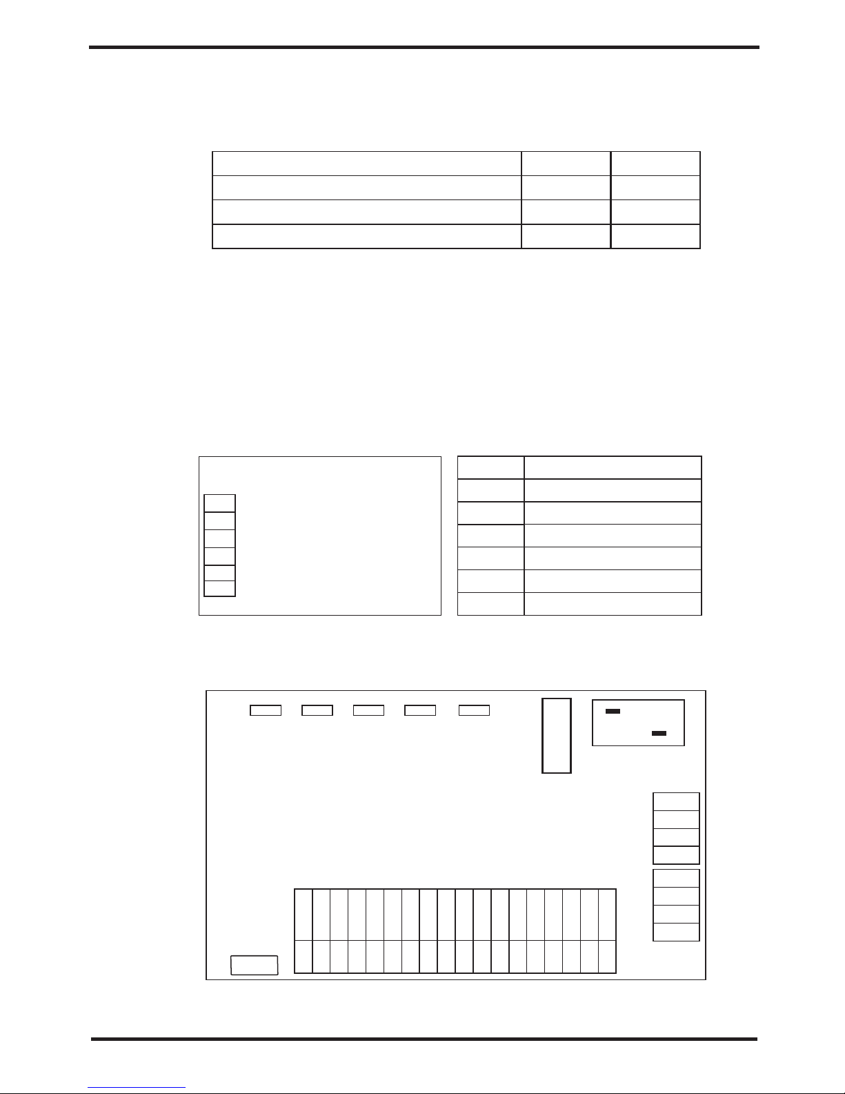
(2) Controller interface diagram and definition
(1) Wire control interface diagram and definition
(2) Parameter list
4.4 Interface drawin
20
V
R
T
A
B
G
Sign
Meaning
V
R
T
A
B
G
Meaning
28℃
28℃
27℃
Remarks
Adjustable
Adjustable
Adjustable
12V(pow er +)
No use
No use
485A
485B
GND(p ower-)
Default
Refrigeration targe t temperature set point
Heating the target temperature set point
Automatic target temerature set point
4.OPERATION AND USE
AC-L
OUT1
OUT2
OUT3
AC-N
OUT4
OUT5
PC1002
GND
GND
GND
GND
GND
GND
GND
GND
GND
GND
GND
GND
GND
GND
GND
GND
GND
GND
0-10V-OUT
AI/D I01
AI/D I03
AI/D I04
AI/D I05
AI/D I06
AI/D I07
AI/D I08
AI/D I09
AI/D I10
AI/D I11
AI/D I02
AI12(50K)
0-5V- IN
PWM- IN
PW M- OU T
+5V
+12V
485_A2
GND
485_B2
485_A1
485_B1
GND
12V
12V
CN9
GND
AI/D I07
T5AL2 50V
FUSE
Page 24
5. MAINTENANCE AND INSPECTION
21
4.OPERATION AND USE
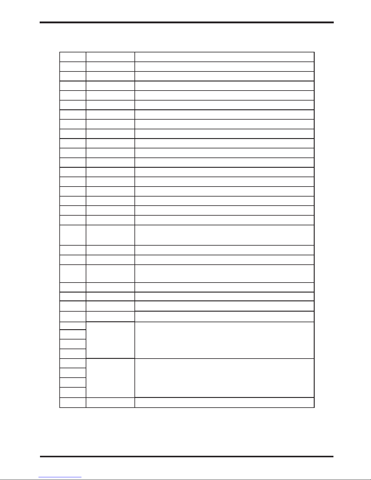
Main board of the input and output interface instructions below
OUT1
OUT2
OUT3
OUT4
OUT5
AC-L
AC-N
AI/DI01
AI/DI02
AI/DI03
AI/DI04
AI/DI05
AI/DI06
AI/DI07
AI/DI08
AI/DI09
AI/DI10
AI/DI11
AI12(50K)
0_5V_IN
PWM_IN
PWM_OUT
0_10V_OUT
+5V
+12V
GND
485_B1
485_A1
12V
GND
485_B2
485_A2
12V
CN9
Sign
Meaning
Number
01
02
03
04
05
06
07
08
09
10
11
12
13
14
15
16
17
18
19
20
21
22
23
24
25
26
27
28
29
30
31
32
33
34
Compressor ( output 220 -230VAC)
Water pump ( output 220-230VAC)
4-way valve ( output 220- 230VAC)
High speed of fan ( output 22 0-230VAC)
Low speed of fan (output 22 0-230VAC)
Live wire ( input 220-230VAC)
Neutral wire ( input 220-230VAC)
Emergency switch input
Water flow switch input
System low pressure input
System high pressure input
Water output temperature ( input )
System fan coil tempera ture( input)
Ambient temperature( input)
Mode switch input
Master-slave machine switch / Antifreeze
temperature(input)
System Exhaust temper ature (input)
Compressor current detection/Pressure sensor(inpu t)
Master-slave machine switch / Feedback signal of EC
fan ( input )
AC fan control ( output )
EC fan control ( output )
+5V ( output )
+12V ( output )
( )
( )
( )
( )
System suction temperature (input)
Water input temperature (input)
( )
Frequency conversion board communications
Color line controller communication
Electronic expansion valve
Page 25

22
Check the water supply de vice and the release often. You should avo id the condition of no
water or air entering into system, as this will influence unit's performance and reliability.
You should clear the pool/spa filter regularly to av oid damage to the unit as a result of the
dirty of clogged filter.
The area around the unit sh ould be dry, cle an and well ventilated. Clean the side heating
exchanger regularly to maintain good heat exchange as conse rve energy .
The operation pressure of the refrigerant system should only be serviced by a certified
technician .
Discharge all wa ter in the water pump and water system ,so that freezing of the water in the
pump or water system does n ot occur. You should discharge the water at the bottom of
water pump if the unit will n ot be used for an extended period of time. You s hould check the
unit thoroughly and fil l the system with water fully before using it for the first time after a
Check the power supply and cable connection often,.Should the unit begin to operate
abnormally, switch it off and contact the qualified technician.
5. MAINTENANCE AND INSPECTION
Page 26

6.2 Cable specification
When the unit will be installed at outdoor, please use the cable which can against UV.
(1) Single phase unit
6.APPENDIX
6.APPENDIX
1. The unit can only be repaired by q ualified installer centre personnel or an a uthorised
dealer.(for Europe marke t)
2. This appliance is not intended for us e by persons (including children) with reduced physical
sensory or mental capabilities, or lack of experience and knowledge, unless they have been
given supervision or instruction concerning use of the appl iance by a person responsible for
their safety. (for Europe market)
Children should be supervised to ensure that they do not play with the appliance.
3. Please make sure that th e unit and power connection have good earthing, otherwise may
cause electrical shock.
4. If the supply cord is dama ged, it must be replaced by the manufacturer or our service agent
or similarly qualifie d person in order to avoid a hazard.
5. Directive 2002/96/EC (WEEE):
The symbol depicting a crossed-out w aste bin that is underneath the appliance indicates
that this product, at the end of its useful life, must be handled separately from domestic
waste, must be taken to a recyclin g centre for electric and electronic devices or handed
back to the dealer when pur chasing an equivalent appliance.
6. Directive 2002/95/EC (RoHs): Th is product is compliant with directive 2002/95/EC (RoHs)
concerning restrictions for the use of harmful substances in electric and electronic devices.
7. The unit CANNOT be installed near the flammable gas. Once t here is any leakage of the gas
, fire can be occur.
8. Make sure that there is circuit breaker for the unit, lack of circuit breaker can lead to
electrical shock or fir e.
9. The heat pump located inside the unit i s equipped with an over-load protection system. It
does not allow for the unit to start for at least 3 minutes from a previous stoppage.
10. The unit can only be repaired b y the qualified personnel of an installer center or an
authorized dealer. (for N orth America market)
11. Installation must be performed in a ccordance with the NEC/CEC by authorized person only.
(for North America market)
12. USE SUPPLY WIRES SUITABLE FOR 75℃.
13. Caution: Single wal l heat exchanger, not suitable for potable water connection.
6.1 Caution & Warning
23
Page 27
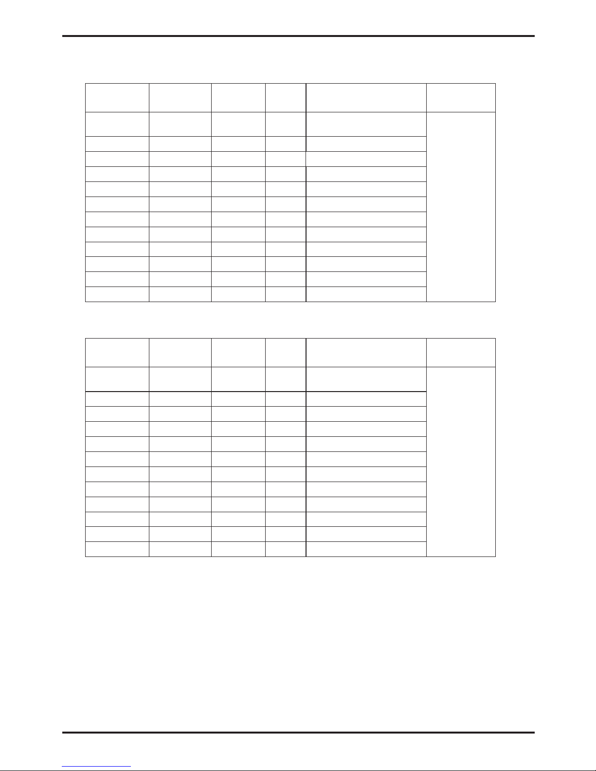
6.2 Cable specification
When the unit will be installed at outdoor, please use the cable which can against UV.
(1) Single phase unit
10~16A
16
~25A
25
~32A
32
~40A
40
~63A
63~75A
75~101A
101~123A
123~148A
148~186A
186~224A
Phase line
MCB
Creepage protector
Signal line
2
×
n 0.5mm
Nameplate
maximum
current
Earth line
No more
than 10A
2
2×1.5mm
2
2×2.5mm
2
2×4mm
2
2×6mm
2
2×10mm
2
2×16mm
2
2×25mm
2
2×25mm
2
2×35mm
2
2×50mm
2
2×70mm
2
2×95mm
20A
32A
40A
40A
63A
80A
100A
125A
160A
225A
250A
280A
2
1.5mm
2
2.5mm
2
4mm
2
6mm
2
10mm
2
16mm
2
mm
25
2
mm
25
2
35mm
2
50mm
2
70mm
2
95mm
30mA less than 0.1 sec
10~16A
16
~25A
25
~32A
32
~40A
40
~63A
63~75A
75~101A
101~123A
123~148A
148~186A
186~224A
Phase line
MCB
Creepage protector
Signal line
2
×
n 0.5mm
Nameplate
maximum
current
Earth line
No more
than 10A
20A
32A
40A
40A
63A
80A
100A
125A
160A
225A
250A
280A
2
1.5mm
2
2.5mm
2
4mm
2
6mm
2
10mm
2
16mm
2
mm
25
2
mm
25
2
35mm
2
50mm
2
70mm
2
95mm
(2) Three phase unit
2
3×1.5mm
2
3×2.5mm
2
3×4mm
2
3×6mm
2
3×10mm
2
×
16mm
3
2
×
25mm
3
2
3×25mm
2
3×35mm
2
3×50mm
2
3×70mm
2
3×95mm
30mA less than 0.1 sec
30mA less than 0.1 sec
30mA less than 0.1 sec
30mA less than 0.1 sec
30mA less than 0.1 sec
30mA less than 0.1 sec
30mA less than 0.1 sec
30mA less than 0.1 sec
30mA less than 0.1 sec
30mA less than 0.1 sec
30mA less than 0.1 sec
30mA less than 0.1 sec
30mA less than 0.1 sec
30mA less than 0.1 sec
30mA less than 0.1 sec
30mA less than 0.1 sec
30mA less than 0.1 sec
30mA less than 0.1 sec
30mA less than 0.1 sec
30mA less than 0.1 sec
30mA less than 0.1 sec
30mA less than 0.1 sec
30mA less than 0.1 sec
6.APPENDIX
24
Page 28
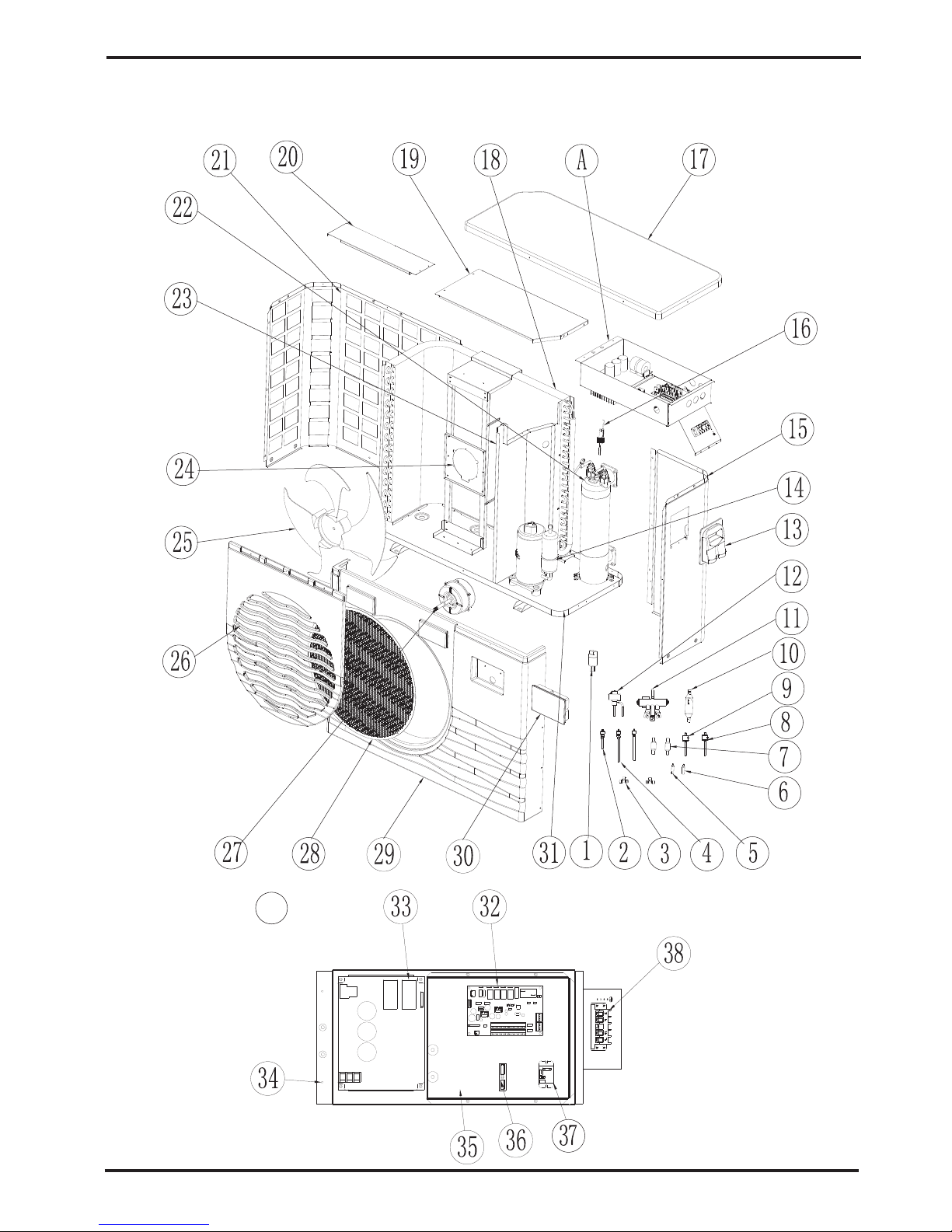
Model and code:OASIS Ci 10
A
6.APPENDIX
25
6.3 Explosive view of the unit
6.APPENDIX
No
1
2
3
4
5
6
7
8
9
10
11
12
13
14
15
16
17
18
19
20
21
22
23
24
25
26
27
28
29
30
31
32
33
34
35
36
37
38
Page 29
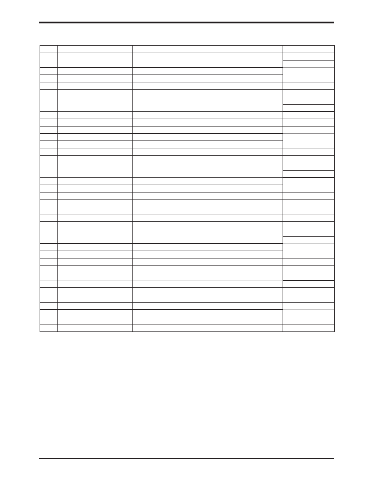
26
6.APPENDIX
Code
20000-360123
20000-140153
2000-1435
20000-140512
2002-1496
20000-140058
2004-1444
2001-3605
20000-360157
2001-1499
2004-1437
20000-140449
32009-220029
20000-110227
32012-210498
20000-360005
32012-210489
32012-120109
32012-210494
32012-210493
32012-210495
32012-120114
32012-210491
32012-210518
20000-270004
32012-210488
20000-330132
32018-210132
32012-210487
95005-310500
32012-210691
95005-310569
20000-310170
32012-210496
32012-210497
2000-3909
20000-360203
4000-3901
Parts name
pressure sensor
Needle
T-Pipe
Needle
reducing straight-way
reducing straight-way
Filter
pressure switch
pressure switch
check valve
4-way Valve and fittings
Electronic Expansion Valve
electronic box
compressor
right panel
flow switch
top cover
heat exchanger
Electrical Box Cover
Supporting Plate
back protection net
titanium heat exchanger
Middle Plate
Fan Motor Support
Fan Blade
Fan Guard
fan motor
fan protection net
Front Plate
Colorful display
Chassis
Pc1002
Inverter drive module
Electrical Box
scale board
Terminal Board(2 bit)
Relay
Terminal Board(5 bit)
No
1
2
3
4
5
6
7
8
9
10
11
12
13
14
15
16
17
18
19
20
21
22
23
24
25
26
27
28
29
30
31
32
33
34
35
36
37
38
Qty
1
2
1
1
1
1
2
1
1
1
1
1
1
1
1
1
1
1
1
1
1
1
1
1
1
1
1
1
1
1
1
1
1
1
1
1
1
1
Page 30
27
6.APPENDIX
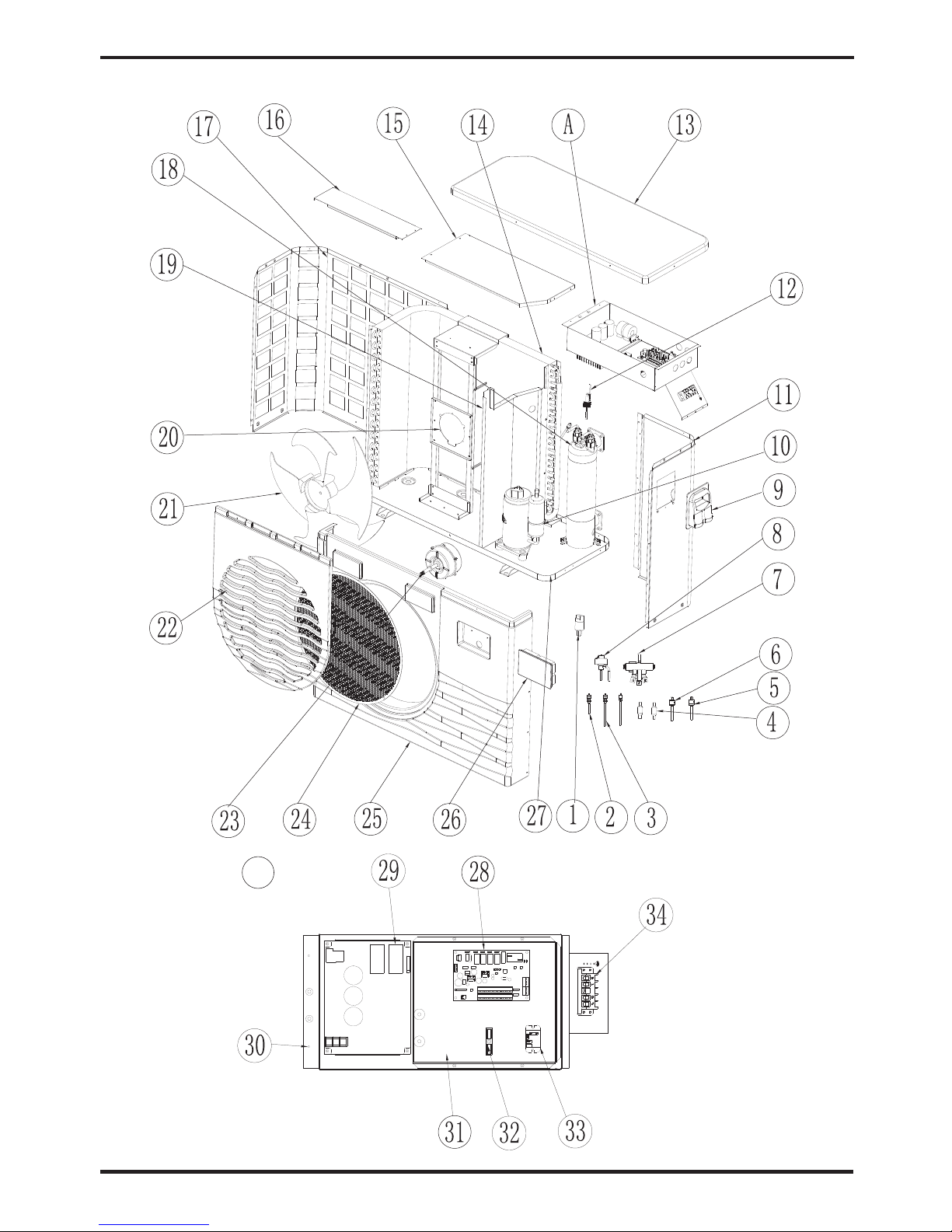
Model and code:OASIS Ci 13
A
6.APPENDIX
Page 31
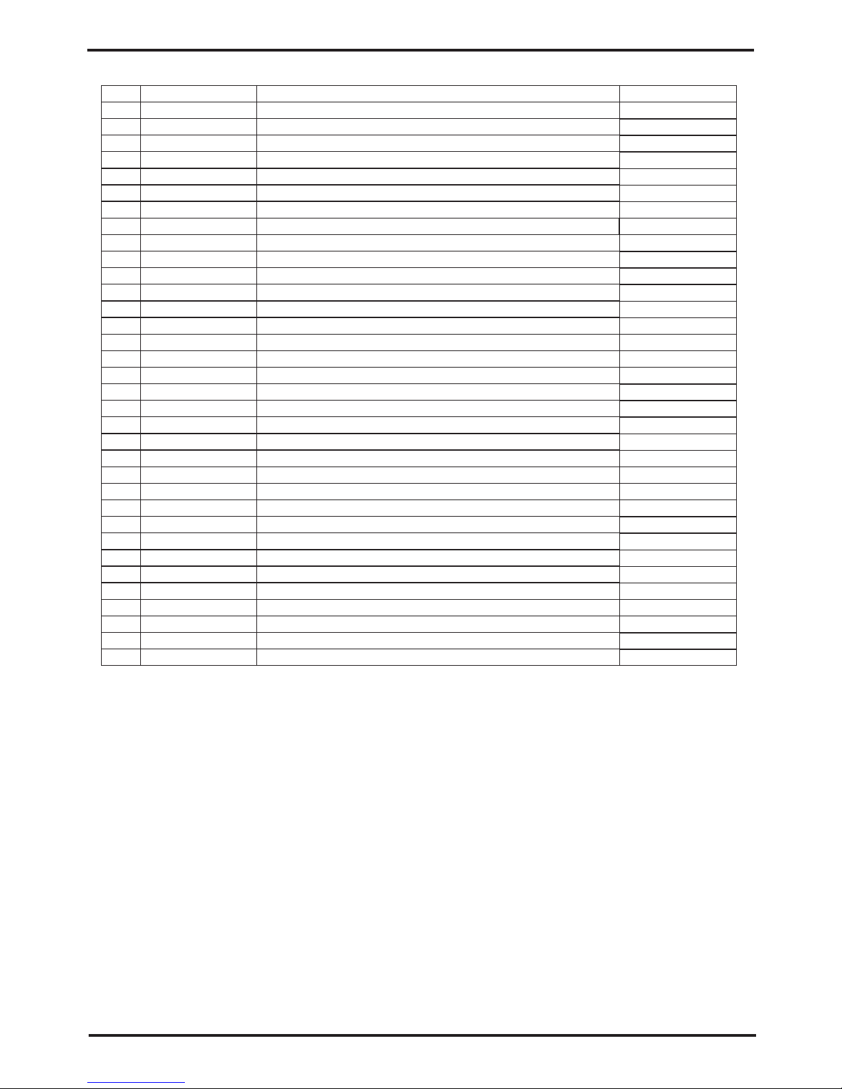
6.APPENDIX
28
Code
20000-360123
20000-140150
20000-140512
2004-1444
20000-360157
2001-3605
2004-1437
20000-140346
32009-220029
20000-110217
32009-210399
20000-360005
32018-210127
32009-120046
32018-210115
32018-210114
32009-210398
32009-120045
32009-210390
32018-210113
20000-270004
32009-210386
20000-330132
32018-210132
32009-210387
95005-310500
32009-210532
95005-310569
20000-310170
32009-210392
32009-210393
2000-3909
20000-360203
4000-3901
Parts name
pressure sensor
Needle
Needle
Filter
pressure switch
pressure switch
4-way Valve and fittings
Electronic Expansion Valve
electronic box
compressor
right panel
flow switch
top cover
heat exchanger
Electrical Box Cover
Supporting Plate
back protection net
titanium heat exchanger
Middle Plate
Fan Motor Support
Fan Blade
Fan Guard
fan motor
fan protection net
Front Plate
Colorful display
Chassis
Pc1002
Inverter drive module
Electrical Box
scale board
Terminal Board(2 bit)
Relay
Terminal Board(5 bit)
No
1
2
3
4
5
6
7
8
9
10
11
12
13
14
15
16
17
18
19
20
21
22
23
24
25
26
27
28
29
30
31
32
33
34
Qty
1
2
1
2
1
1
1
1
1
1
1
1
1
1
1
1
1
1
1
1
1
1
1
1
1
1
1
1
1
1
1
1
1
1
Page 32
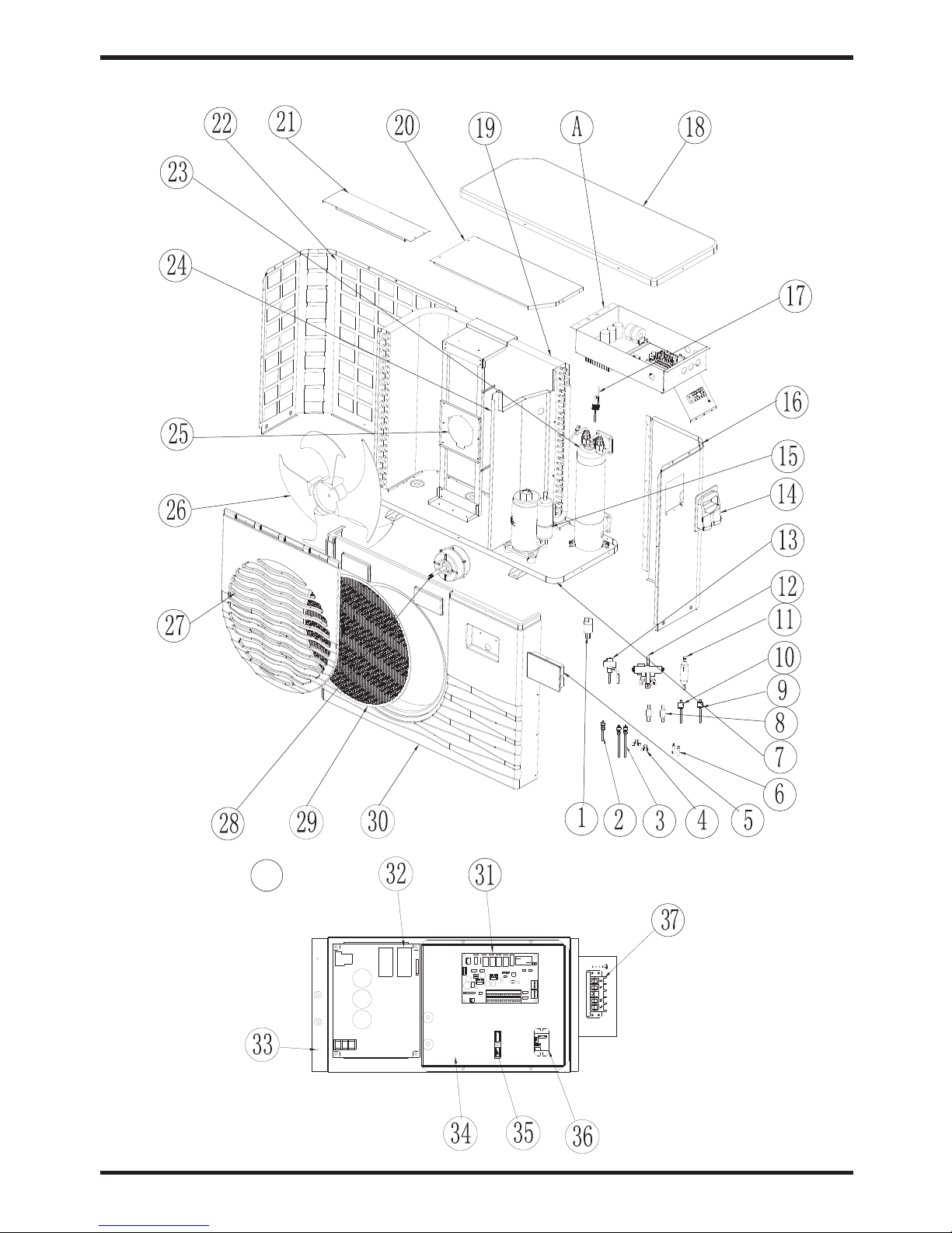
29
Model and code:OASIS Ci 17
6.APPENDIX
A
No
1
2
3
4
5
6
7
8
9
10
11
12
13
14
15
16
17
18
19
20
21
22
23
24
25
26
27
28
29
30
31
32
33
34
35
36
37
6.APPENDIX
Page 33
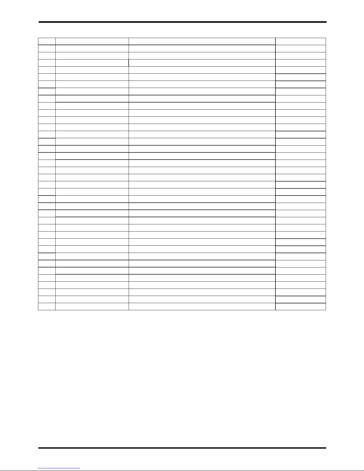
30
Code
20000-360123
20000-140512
20000-140150
2000-1435
95005-310500
20000-140143
32018-210125
2004-1444
20000-360157
2001-3605
2001-1499
2001-1491
20000-140450
32009-220029
20000-110289
32018-210106
20000-360005
32018-210127
32018-120021
32018-210115
32018-210114
32018-210107
32019-120013
32018-210110
32018-210113
20000-270004
32009-210386
20000-330132
32018-210132
32009-210387
95005-310569
20000-310165
32018-210108
32018-210109
2000-3909
20000-360203
4000-3901
Parts name
pressure sensor
Needle
Needle
T-Pipe
Colorful display
reducing straight-way
Chassis
Filter
pressure switch
pressure switch
check valve
4-way Valve and fittings
Electronic Expansion Valve
electronic box
compressor
right panel
flow switch
top cover
heat exchanger
Electrical Box Cover
Supporting Plate
back protection net
titanium heat exchanger
Middle Plate
Fan Motor Support
Fan Blade
Fan Guard
fan motor
fan protection net
Front Plate
PC1002
Inverter drive module
Electrical Box
scale board
Terminal Board(2 bit)
Relay
Terminal Board(5 bit)
No
1
2
3
4
5
6
7
8
9
10
11
12
13
14
15
16
17
18
19
20
21
22
23
24
25
26
27
28
29
30
31
32
33
34
35
36
37
Qty
1
1
2
2
1
2
1
2
1
1
1
1
1
1
1
1
1
1
1
1
1
1
1
1
1
1
1
1
1
1
1
1
1
1
1
1
1
6.APPENDIX
Page 34
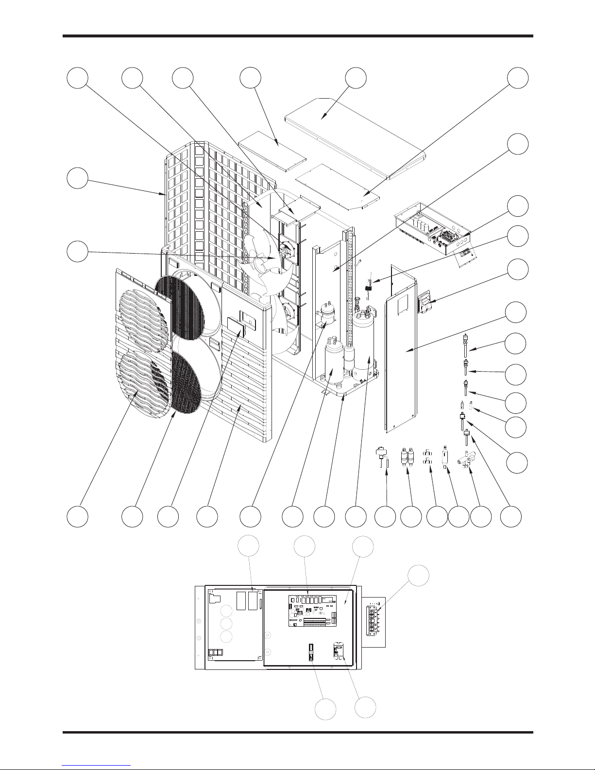
31
Model and code:OASIS Ci 21
1
2
3
4
6
5
8
7
109 11
14
12
13
15
16
17
18
19
21
20
22
23
25
24
26
27
29
28
30
31
32
33
34
35
36
3738
6.APPENDIX
No
1
2
3
4
5
6
7
8
9
10
11
12
13
14
15
16
17
18
19
20
21
22
23
24
25
26
27
28
29
30
31
32
33
34
35
36
37
38
6.APPENDIX
Page 35
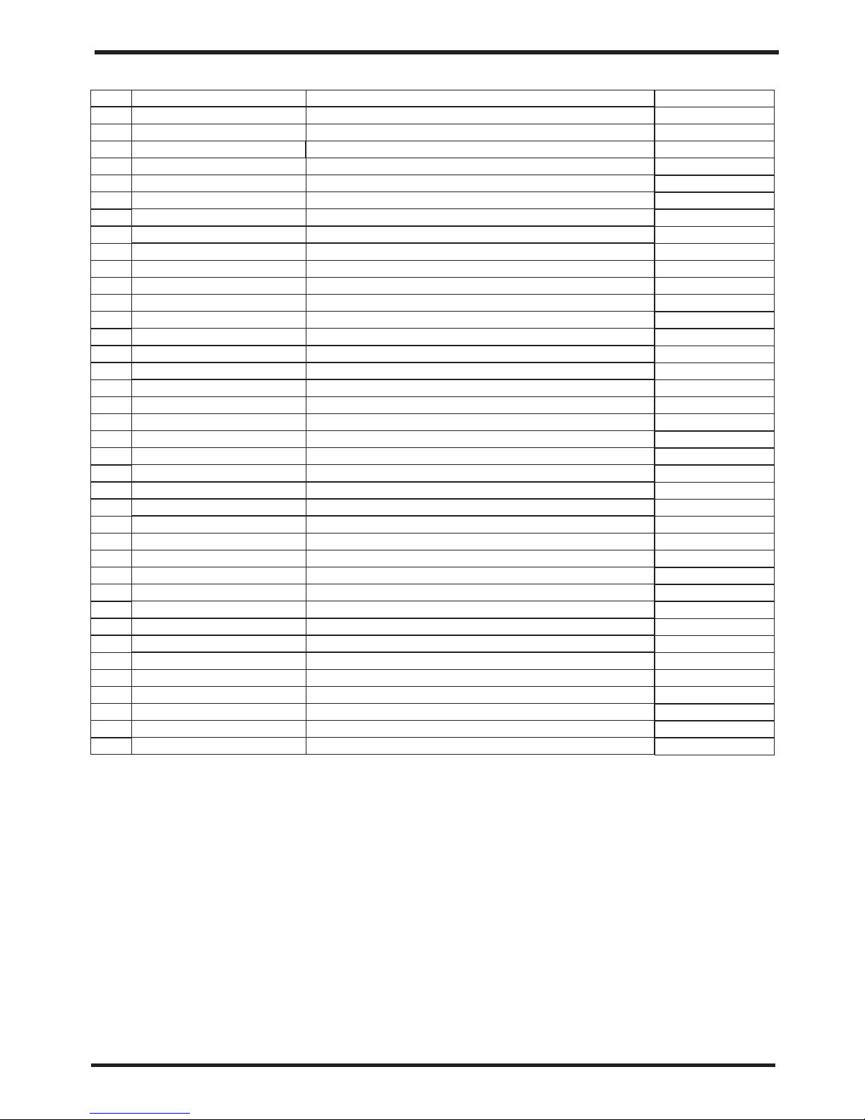
32
Code
32019-210066
95005-310500
32018-210132
32019-210065
20000-270004
32019-210068
20000-330132
32019-120008
32019-210063
32019-210070
32018-210127
32019-210071
32019-210069
32019-210072
20000-360005
32009-220029
32019-210067
20000-140150
20000-140150
20000-140512
20000-140143
2001-3605
20000-360157
2001-1491
2001-1499
2000-1435
2004-1444
20000-140401
32019-120014
32019-210064
20000-110296
3600-1401
20000-310165
95005-310569
32019-210073
4000-3901
20000-360203
2000-3909
Parts name
Junction box
Variable diameter
Check valve
fluid reservoir
Electric box lining board
Front Plate
Colorful display
fan protection net
Fan Guard
Fan Blade
back protection net
fan motor
heat exchanger
Fan Motor Support
Supporting Plate
top cover
Electrical Box Cover
Middle Plate
Electrical Box
flow switch
right panel
Needle
Needle
Needle
pressure switch
pressure switch
4-way Valve and fittings
T-Pipe
Filter
Electronic Expansion Valve
titanium heat exchanger
Chassis
compressor
Inverter drive module
PC1002
Terminal Board(5 bit)
Relay
Terminal Board(2 bit)
No
1
2
3
4
5
6
7
8
9
10
11
12
13
14
15
16
17
18
19
20
21
22
23
24
25
26
27
28
29
30
31
32
33
34
35
36
37
38
Qty
1
1
1
1
1
1
1
1
1
1
1
1
1
1
1
1
1
1
1
1
2
1
1
1
1
2
2
1
1
1
1
1
1
1
1
1
1
1
6.APPENDIX
Page 36
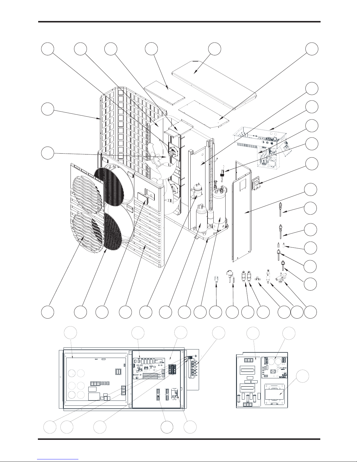
33
Model and code:OASIS Ci 25T
6.APPENDIX
6.APPENDIX
44 45
46
1
2
3
4
6
5
8
7
109 11
15
12
13
16
17
18
19
21
20
23
25
24
26
28
31
29
32
33
34
14
22
27
30
No
1
2
3
4
5
6
7
8
9
10
11
12
13
14
15
16
17
18
19
20
21
22
23
24
25
26
27
28
29
30
31
32
33
34
35
36
37
38
39
40
41
42
43
44
35
36
37
38
39
40
414243
Page 37
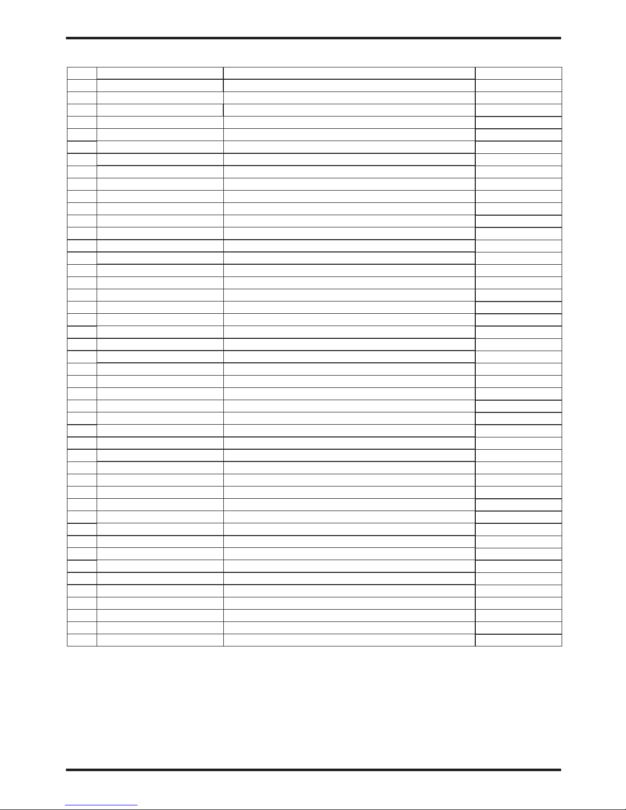
6.APPENDIX
34
Code
32019-210066
95005-310500
32018-210132
32019-210065
20000-270004
32015-210028
20000-330132
32015-120012
32019-210063
32019-210070
32018-210127
32019-210071
32015-210018
32019-210105
32019-210098
20000-360005
32009-220029
32015-210020
20000-140512
20000-140150
20000-140143
2001-3605
20000-360157
2001-1491
2001-1499
2000-1435
2004-1444
20000-140027
20000-140401
20000-360123
32015-120015
32019-210064
20000-110341
20000-140579
20000-310179
95005-310569
32019-210073
20000-390180
20000-360203
2000-3909
20000-390049
20000-390046
20000-390047
20000-310180
Part name
p
F
g
b
B
F
H
m s
p
T
b c
p
b
Water
Junction box
R
Reducing
High p
Low p
W
Check valve
Junction
e v
Pressure sensor
T
C
Fluid reservoir
I
Electric box lining board
b
b
Terminal
Terminal
Terminal plate
Three phase filter
ZL10 V3
Three - phase ac monitor
Front late
Colorful display
an protection net
Fan uard
Fan lade
ack protection net
an motor
eat exchanger
Fan otor upport
Supporting late
op cover
Electrical ox over
Middle late
Electrical ox
Electrical box 2
flow switch
ight panel
Needle
Needle
ressure switch
ressure switch
4- ay Valve
T-
Filter
Filter
Electronic xpansion alve
itanium heat exchanger
Chassis
ompressor
nverter drive module
PC1002
Terminal oard(5 bit)
Relay
Terminal oard(2 bit)
No
1
2
3
4
5
6
7
8
9
10
11
12
13
14
15
16
17
18
19
20
21
22
23
24
25
26
27
28
29
30
31
32
33
34
35
36
37
38
39
40
41
42
43
44
Qty
1
1
2
1
2
1
2
1
1
1
1
1
1
1
1
1
1
1
1
2
2
1
1
1
1
1
1
1
1
1
1
1
1
1
1
1
1
1
1
2
1
4
1
1
Page 38

Note:
Page 39

Page 40

Code:2 01708 18- 00 02
 Loading...