

Page 1
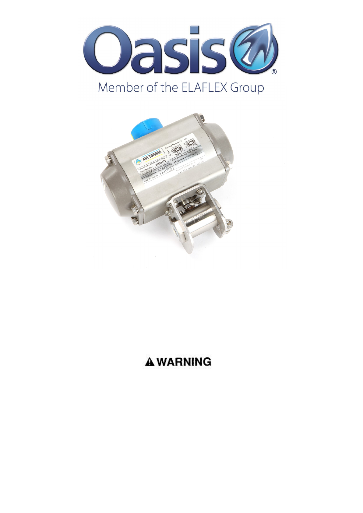
BV700 Series
Actuated Ball Valve SAE
Instruction Manual
Failure to follow these instructions or to properly install and maintain this equipment could result in gas
leakage, fire or explosion causing property damage and personal injury or death.
Oasis products must be installed, operated and maintained by trained and competent personnel in
accordance with all applicable local codes, rules and regulations in addition to the Oasis Instructions.
Oasis Engineering Ltd. will not be held liable in such circumstances where installation, operation and
maintenance procedures were performed by incompetent personnel resulting in improper assembly, unsafe
operation, equipment damage or personal injury.
Oasis Engineering Ltd
129 Birch Avenue, Tauranga, New Zealand.
T: +64 7 928 3808 F: +64 7 928 3809
W: www.OasisNGV.com
Page 2
Safety
Warning!
High pressure gas and gas equipment can cause serious harm to
both infrastructure and personnel if safety precautions are not
followed.
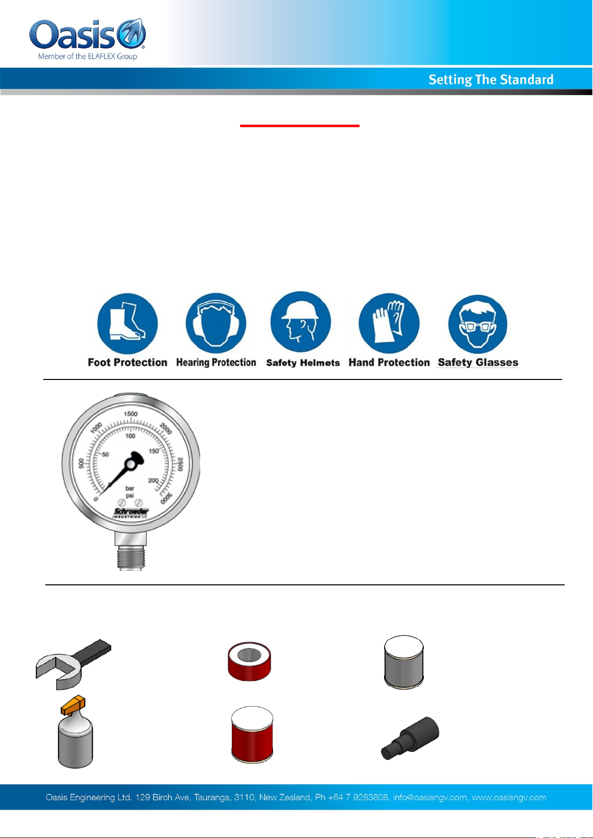
Oasis recommends considering the use of the following PPE when
working with high pressure along with any other site specific health
and safety requirements:
Tools Required
(Wrenches)
Spray bottle
(Snoop or soapy
water)
Ensure the system is clean of debris,
vented and isolated before any
installation or servicing work is carried
out.
Thread Tape Spanner
Silicone Grease
(Rocol MX22 or
similar)
For all O-rings
Anti Seize Grease
- Swagelok Silver Goop
- Omega 99
- or similar
Oasis Plastic Tool
(BV-ASST) or Similar
We reserve the right to modify product specifications without prior notice.
2
BV700-INS-04 3618 © Oasis Engineering Limited
Page 3
Installation Instructions
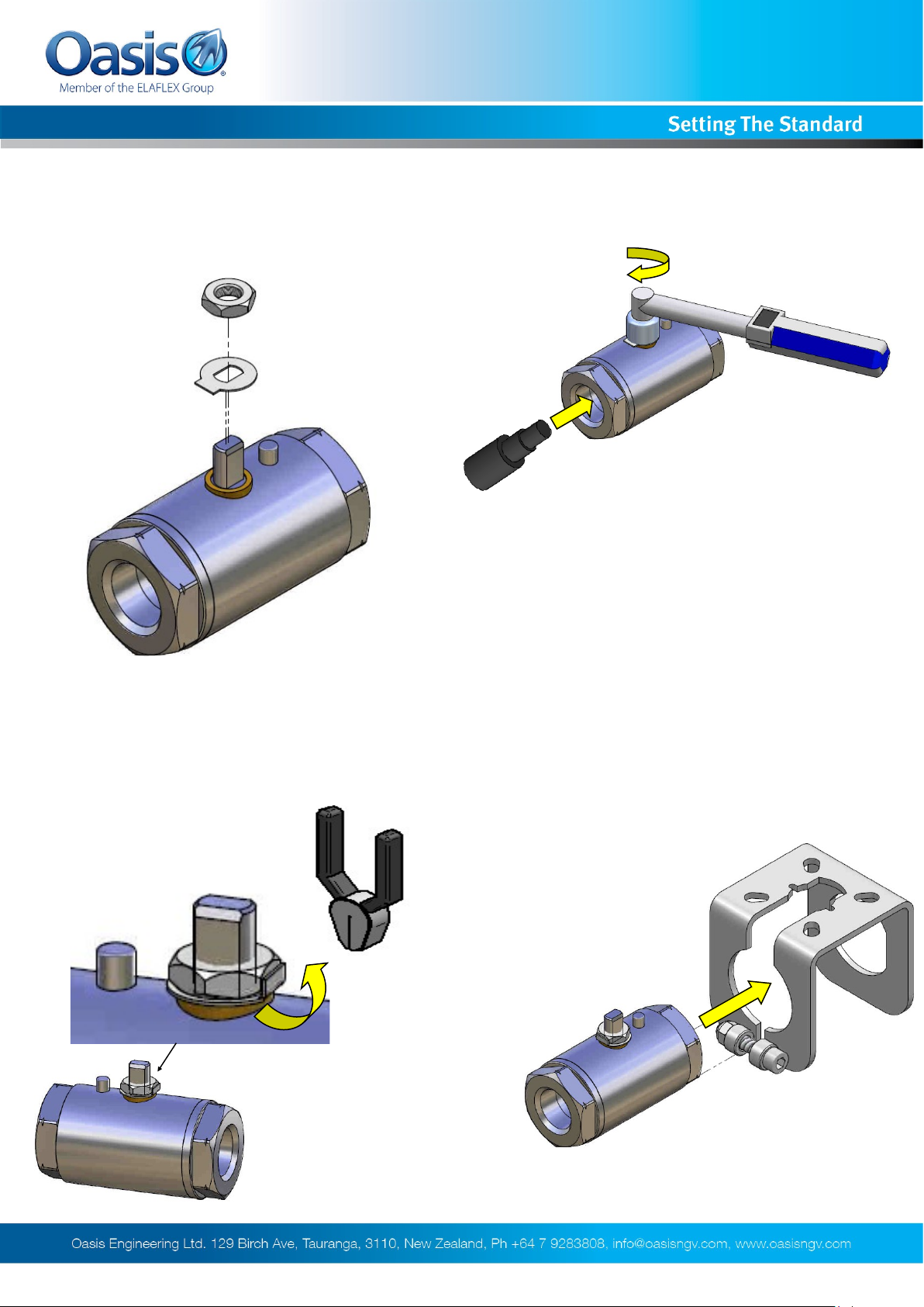
If valve not supplied with actuator or bracket follow these instructions
1. If fitting an existing valve with an actuator
remove existing handle and install the lock tab
and half nut.
2. Tighten the half nut to the required
torque.
Stem nut tightening torque
BV703 = 3Nm
BV704 = 3Nm
BV706 = 6Nm
BV708 = 6Nm
3. Use pliers and crush the lock tab onto
the nut.
4. Insert the ball valve into the actuator
mount so that the stop pin goes in first.
We reserve the right to modify product specifications without prior notice.
3
BV700-INS-04 3618 © Oasis Engineering Limited
Page 4
Installation Instructions
If valve not supplied with actuator or bracket follow these instructions
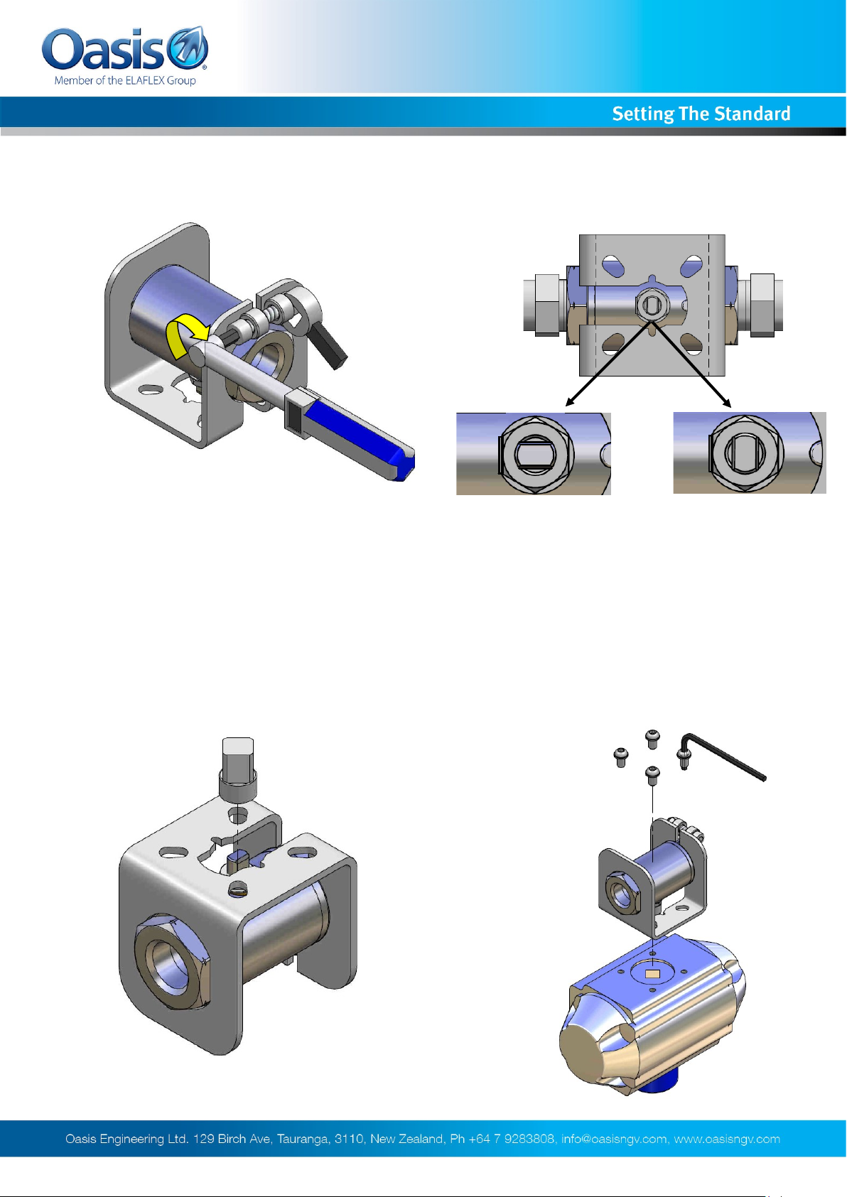
5. Tighten the lock bolt to the
recommended torque.
Actuator mount bolt tightening
torque
BV703 = 2Nm
BV704 = 1Nm
BV706 = 4Nm
BV708 = 4Nm
6. Set the valve to the required fail open/fail
close position as required.
Valve in open position
Stem along the body
Fail Open
Valve in closed position
Stem across the body
Fail Closed
7. Install the drive dog over the stem.
8. Tighten on the actuator ensuring the drive
dog is correctly located.
We reserve the right to modify product specifications without prior notice.
4
BV700-INS-04 3618 © Oasis Engineering Limited
Page 5
Installation Instructions
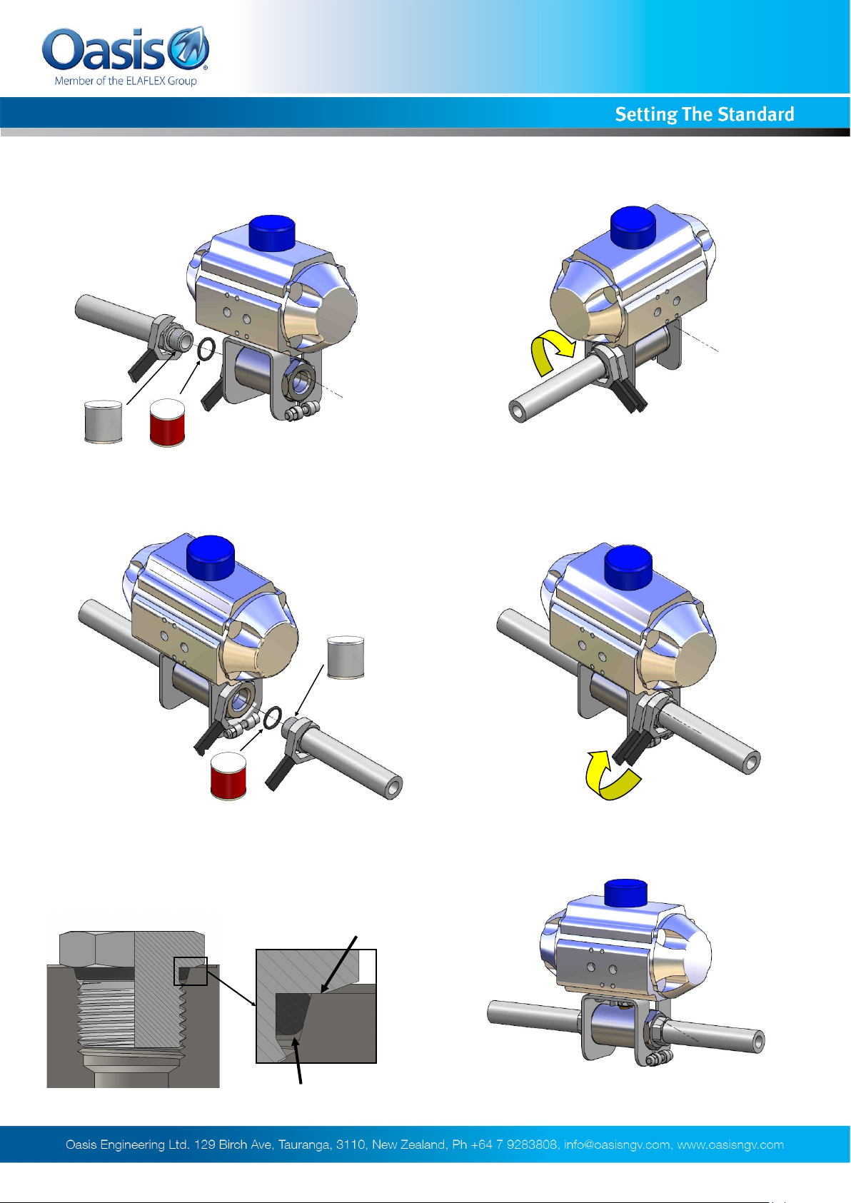
1. Apply anti seize to thread and silicone
grease to the O-ring. Install the O-ring on
the fitting if not pre-installed.
3. Apply anti seize to thread and silicone
grease to the O-ring. Install the O-ring on
the fitting if not pre-installed.
2. Screw the fitting into the body and torque
to the fitting suppliers recommended
tightening torque.
4. Screw the fitting into the body and torque
to the fitting suppliers recommended
tightening torque.
5. Correctly tightened SAE port fittings should
bottom out on the port face and the O-ring
should neatly fill the void creating the seal.
Faces touch
O-ring
We reserve the right to modify product specifications without prior notice.
6. Assembly is complete.
5
BV700-INS-04 3618 © Oasis Engineering Limited
Page 6
Installation Instructions
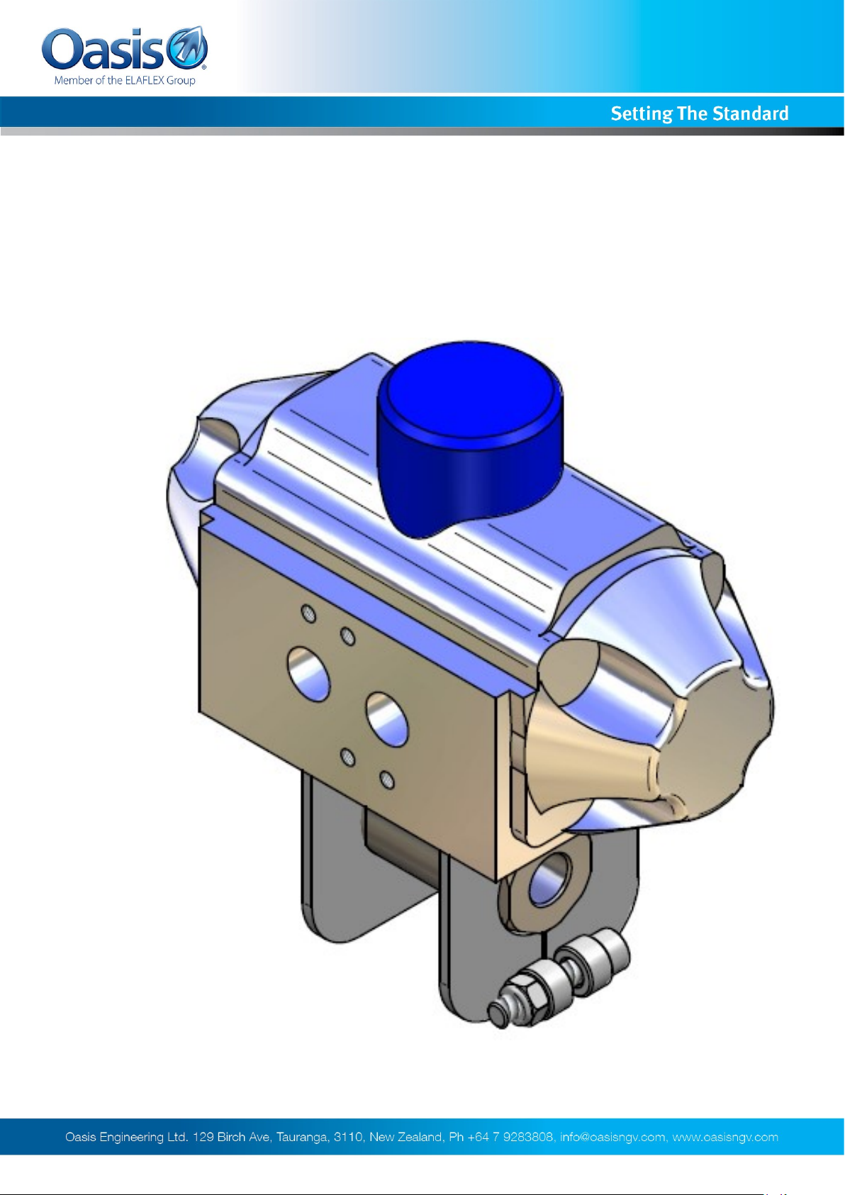
Oasis recommends that for valves bigger than 3/4” the
actuator bracket is mounted separately using the mounting
holes in the supplied actuator bracket.
BV702/703/704 Actuator Bracket Design
We reserve the right to modify product specifications without prior notice.
6
BV700-INS-04 3618 © Oasis Engineering Limited
Page 7
Installation Instructions
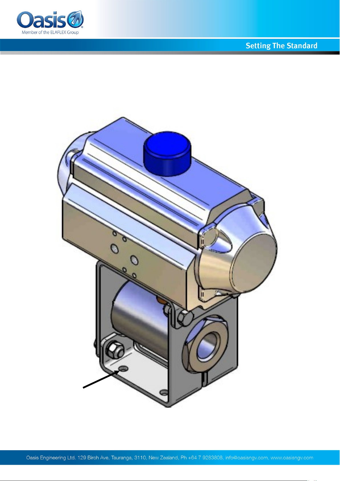
BV706/708 Actuator Bracket Design
Mounting
holes
For mounting holes pattern please refer to Actuated Ball Valves Specification sheet.
7
We reserve the right to modify product specifications without prior notice.
BV700-INS-04 3618 © Oasis Engineering Limited
Page 8
Operation Instructions
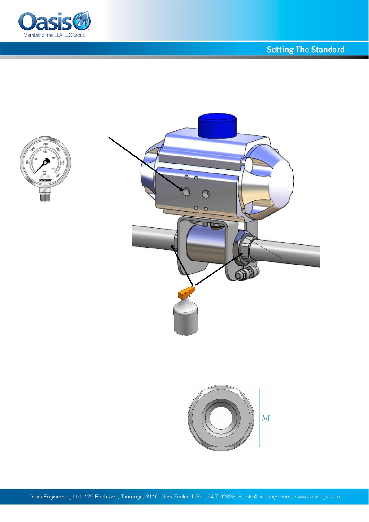
1. Connect air line and check connections for leaks.
For oasis standard actuators the
left port is the inlet port used to
activate the actuator.
MAX 8 Bar
Do not operate the actuator
with supply pressure greater
than 8 Bar (116 psi). Doing so
may damage the actuator and
void the warranty.
Recommended Spanners
for End Caps:
BV702 = 25mm
BV703 = 28mm
BV704 = 34mm
BV706 = 50mm
BV708 = 60mm
Check connections for leaks using
snoop or soapy water.
We reserve the right to modify product specifications without prior notice.
8
BV700-INS-04 3618 © Oasis Engineering Limited
Page 9
Servicing
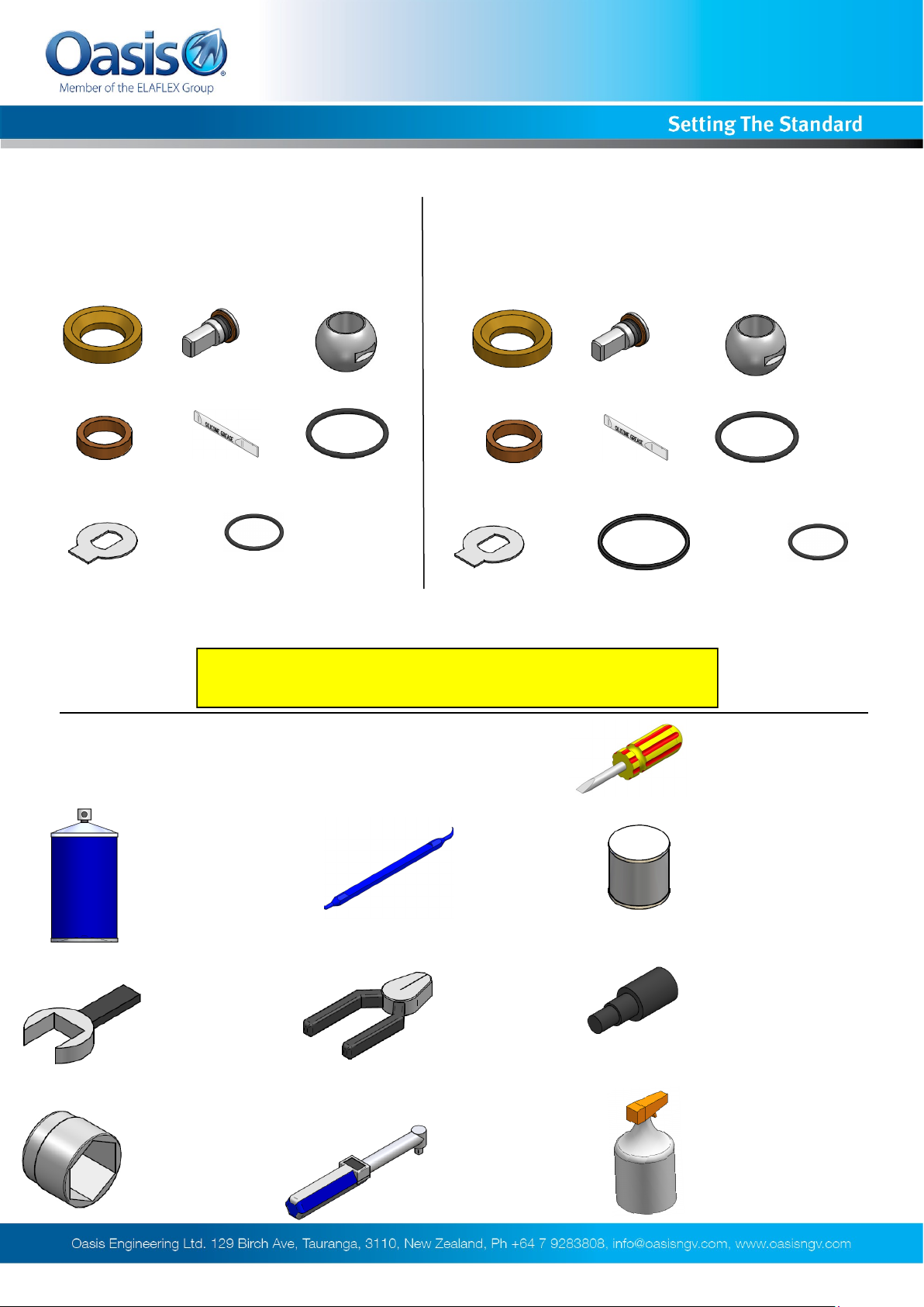
Service Kit Parts
BV702 — BV703 — BV704** BV706** — BV708**
2 x Seats^ 1 x Stem 1 x Ball
1 x Gland
1 x Locking Tab*
only used when servicing actuated ball valves.
** It is normal for the service kit to include a ball with a small hole in the bottom
^ For low pressure service kits, the seats will be supplied with an O-ring installed
1 x Silicone
2 x SAE Fitting O-ring
1 x Cap O-ring
(908 Nitrile 90)
2 x Seats^ 1 x Stem 1 x Ball
1 x Gland
1 x Locking Tab*
1 x Cap Backup O-ring
The Complete Oasis Seal Kit must be used
1 x Cap O-ring 1 x Silicone
2 x SAE Fitting O-rings
(BV706 - 912 Nitrile 90,
916 Nitrile 90 for Matched
Bore Valves)
(BV708 - 916 Nitrile 90,
920 Nitrile 90 for Matched
Bore Valves)
Tools Required
Cleaner (Warm Soapy
Water or Similar)
Spanner
(Wrenches)
Sockets
Pick Tool
Part Number:
TOOL-PICK
(Sold separately )
Pliers
Torque Wrench
Small flat
screw driver
Anti Seize Grease
(Loctite 771 or Similar)
For All Threads
Oasis Plastic Tool
(BV-ASST) or Similar
Snoop or
Soapy Water
We reserve the right to modify product specifications without prior notice.
9
BV700-INS-04 3618 © Oasis Engineering Limited
Page 10
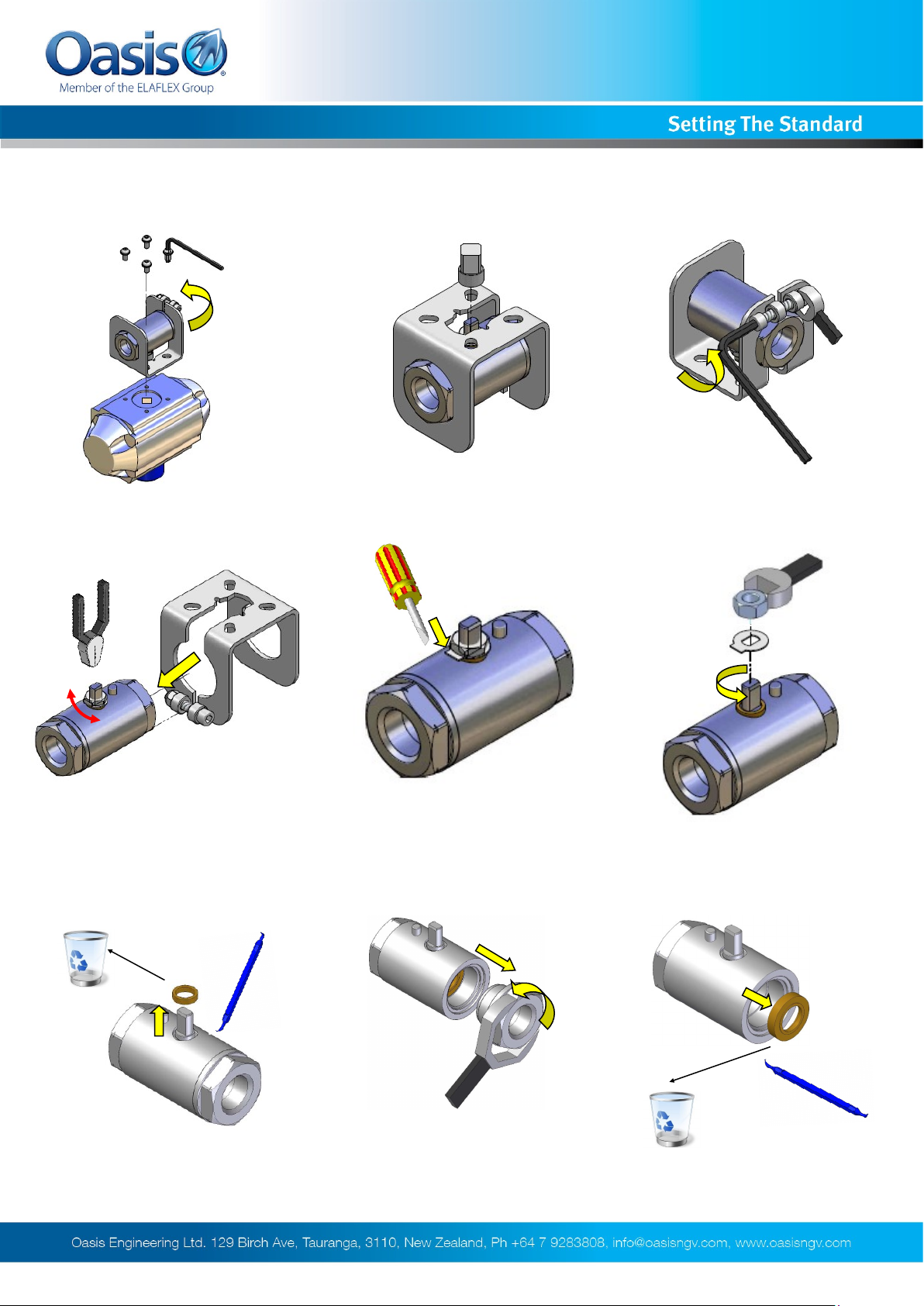
valve.
Servicing - Disassembly
2. Remove drive dog. 3. Undo clamp. 1.Remove actuator from
4.Remove valve.
Open and close valve to ensure
all trapped gas is released
7. Discard gland.
8. Remove end cap.
6. Remove nut and tab. 5. Fold down met-
9.Discard seat.
We reserve the right to modify product specifications without prior notice.
10
BV700-INS-04 3618 © Oasis Engineering Limited
Page 11
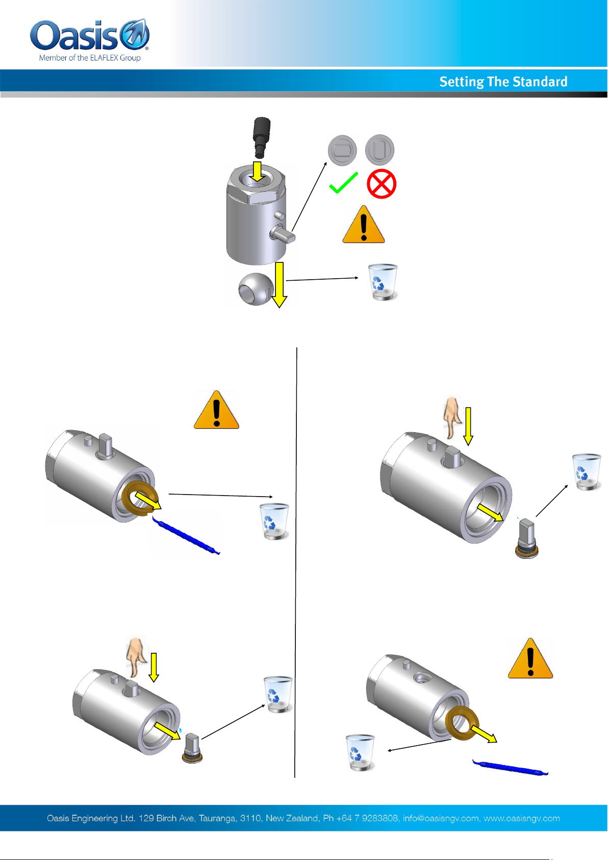
10. Remove ball.
Servicing - Disassembly
BV702 — BV703
11. Remove 2nd seat first.
Do not
scratch body
12. Remove and discard stem. 12. Remove and discard 2nd seat.
BV704 - BV706 - BV708
11. Remove stem first.
We reserve the right to modify product specifications without prior notice.
Do not
scratch body
11
BV700-INS-04 3618 © Oasis Engineering Limited
Page 12
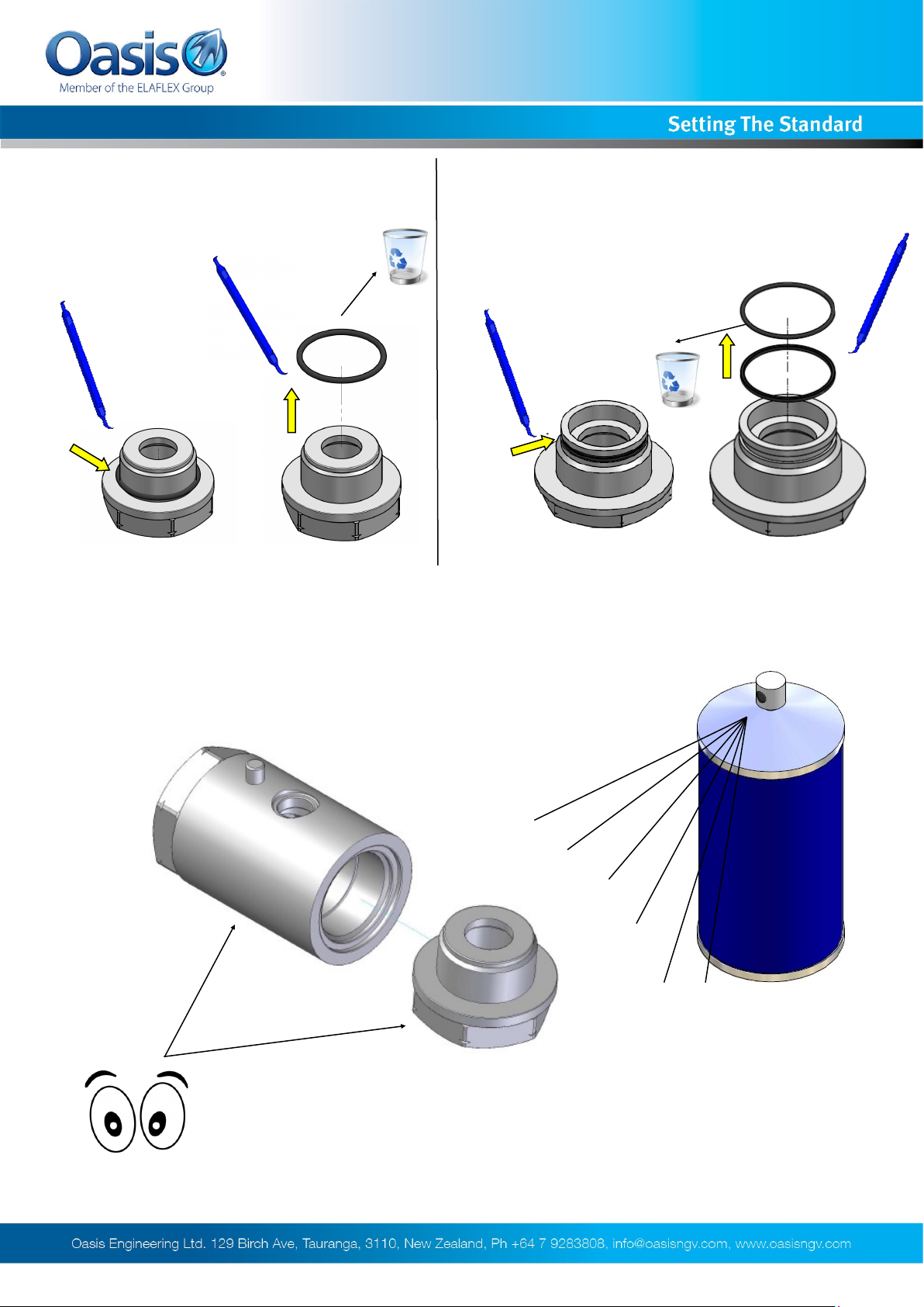
Servicing - Disassembly
BV702 - BV703 - BV704 BV706 - BV708
14. Remove cap O-ring and discard. 14. Remove cap O-rings and discard.
15. Clean body and end cap, visually check parts for damage.
We reserve the right to modify product specifications without prior notice.
12
BV700-INS-04 3618 © Oasis Engineering Limited
Page 13
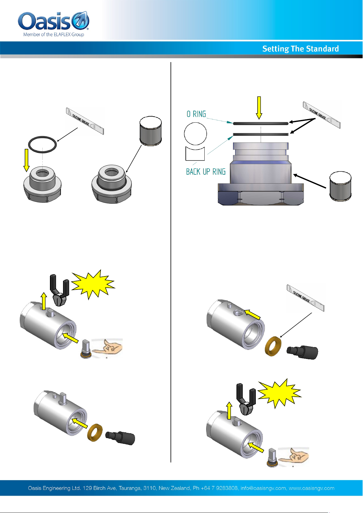
Servicing - Assembly
BV702 — BV703 — BV704
1. Fit O-ring.
BV702 — BV703
BV706 — BV708
1. Fit end cap O-rings.
BV704 - BV706 - BV708
2. Insert stem assembly first.
Click
3. Insert first seat.
2. Apply silicone grease to new seat and
install. Take care not to pinch O-ring when
installing low pressure seat.
3. Insert stem assembly.
Click
We reserve the right to modify product specifications without prior notice.
13
BV700-INS-04 3618 © Oasis Engineering Limited
Page 14
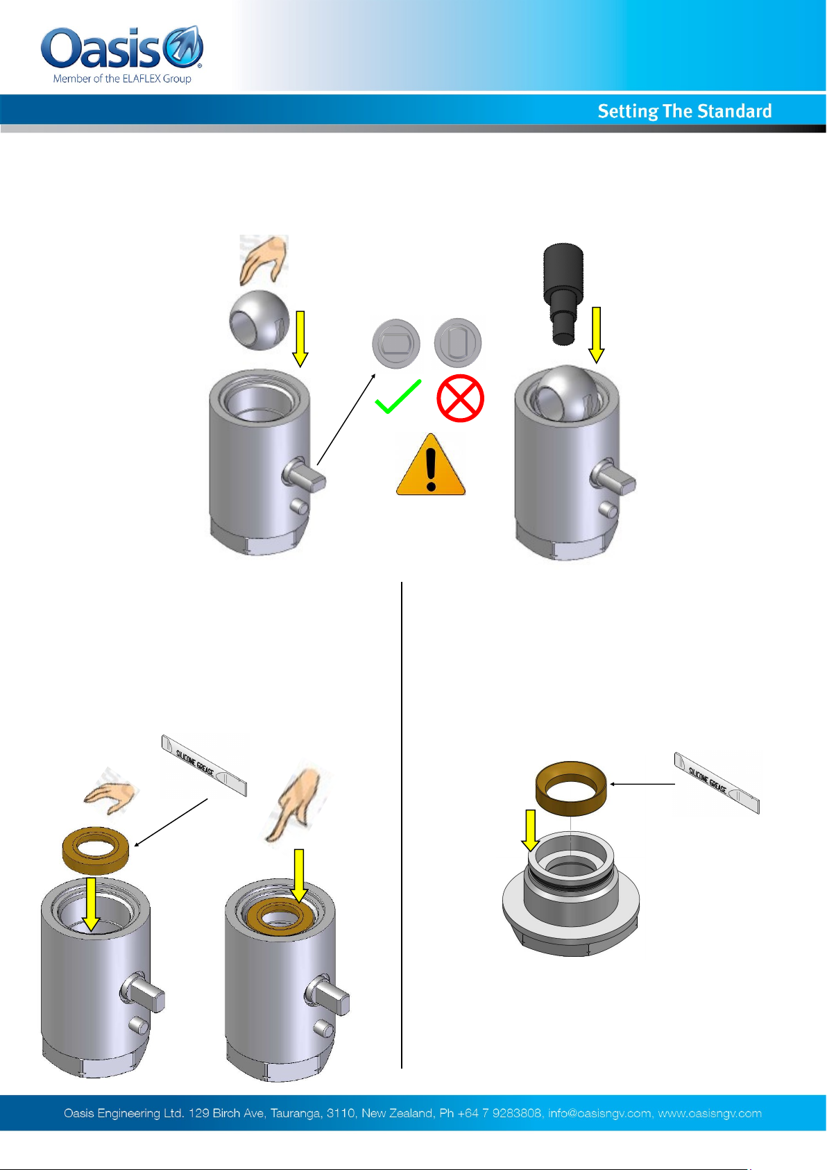
4. Insert ball.
Servicing - Assembly
BV702 - BV703 - BV704 - BV706 - BV708
5. Apply silicone grease to new seat and
install. Take care not to pinch O-ring when
installing low pressure seat.
BV706 — BV708 BV702 — BV703 — BV704
5. Apply silicone grease to new seat and install
in cap. Take care not to pinch O-ring when installing low pressure seat.
We reserve the right to modify product specifications without prior notice.
14
BV700-INS-04 3618 © Oasis Engineering Limited
Page 15
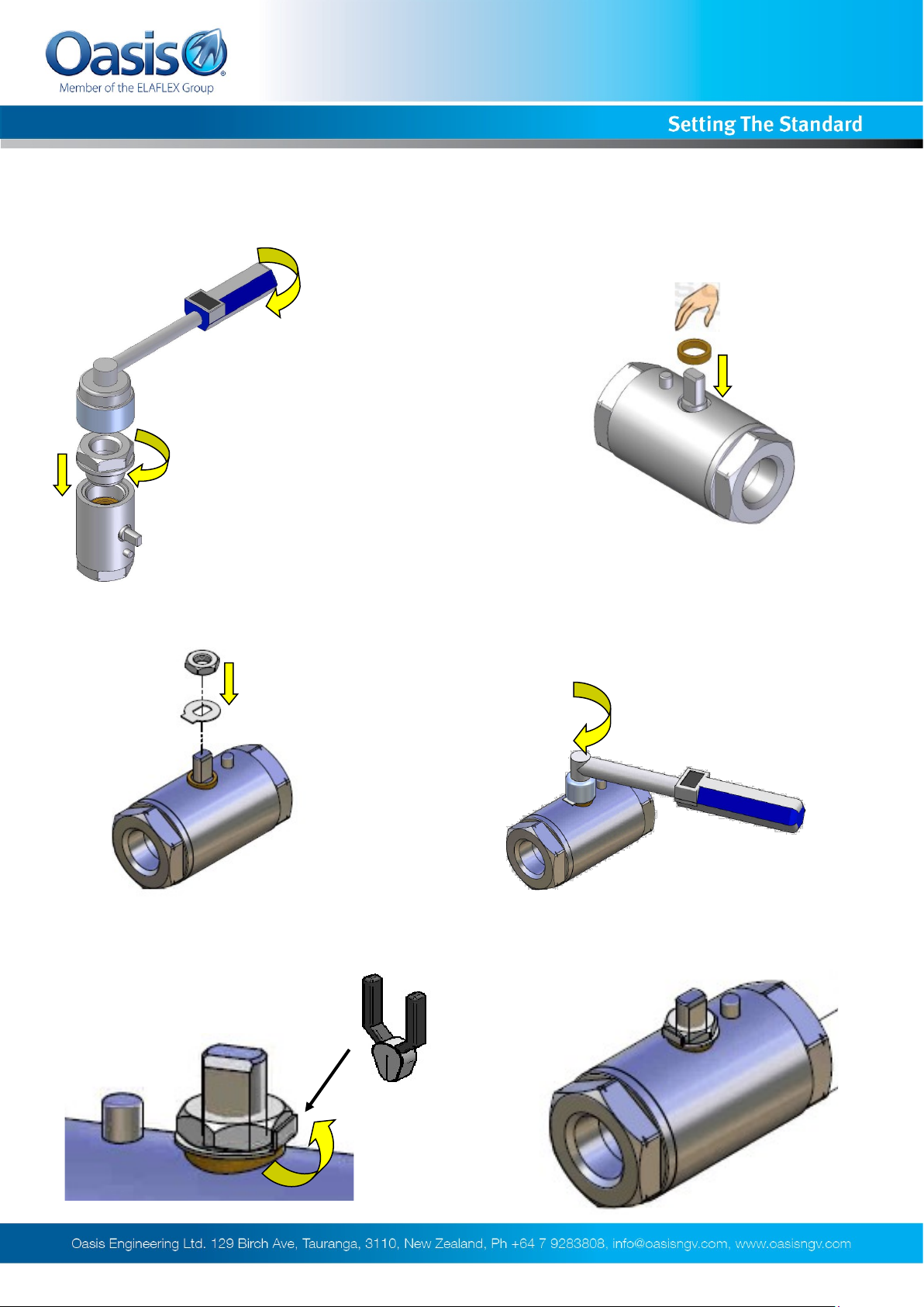
Servicing - Assembly
BV702 - BV703 - BV704 - BV706 - BV708
6. Tighten on end cap.
Recommended
End Cap Torques:
BV702=35Nm
BV703=50Nm
BV704=60Nm
BV706=120Nm
BV708=120Nm
8. Install the lock tab and the nut.
7. Install gland.
9. Tighten stem nut.
Recommended
Handle Nut Torques:
BV702=3Nm
BV703=3Nm
BV704=3Nm
BV706=6Nm
BV708=6Nm
10. Using pliers bend the lock tab upwards
so that it is tight against the nut .
We reserve the right to modify product specifications without prior notice.
11. Servicing complete, follow installation instructions from step 4 on page 3 for
re-installation of product.
15
BV700-INS-04 3618 © Oasis Engineering Limited
 Loading...