

Page 1

MOST
Media Oriented Systems Transport
Multimedia and Control
Networking Technology
Amplifier 4 MOST
Version: 2.0
User Manual
Document Information:
Version: 2.0-03
Release Date: 2003-07-23
®
*X11293*
© Copyright 2002 - 2003 OASIS SiliconSystems
Page 2

Amplifier 4 MOST
User Manual
Intellectual Property
© Copyright 2002 - 2003 OASIS SiliconSystems. Duplication of this document without permission is
prohibited. All rights reserved. The information within this document is OASIS - SiliconSystems
intellectual property. Please make sure that all Information within a document marked as ‘Confidential’
is handled appropriately. The confidential ranking of a document can be found in the footer of every
page.
Trademarks
All trademarks used in this document are proprietary of their respective owners. MOST and OptoLyzer
are internationally registered trademarks.
Patents
There are a number of patents and patents pending on the MOST technology. The rights to these
patents are not granted without any specific agreement between the users and the patent owners.
Preliminary Product Information
A Preliminary Product Information document describes a product, which is in limited production and
subject to change. OASIS SiliconSystems has worked diligently to ensure that the information in this
document is accurate and reliable. However, the information in this document is subject to change
without notice and is provided "as is" without warranty of any kind (expressed or implied).
Further Information
For more information on OASIS SiliconSystems products, including integrated circuits, software, and
MOST development tools and modules, contact one of our offices below, or visit our web site:
www.oasis.com www.oasis.de
OASIS SiliconSystems, Inc. OASIS SiliconSystems AG
1120 South Capital of Texas Highway Bannwaldallee 48
Building 2, Suite 100 D-76185 Karlsruhe
Austin, Texas 78746 USA Germany
Fon: (+1) 512 306 8450 Fon: (+49) (0) 721 6 25 37 - 0
Fax: (+1) 512 306 8442 Fax: (+49) (0) 721 6 25 37 - 119
OASIS Silicon Systems, Inc. OASIS SiliconSystems KK
38600 Van Dyke Avenue, Suite 220 Shin-Yokohama UU Bld. 5F
Sterling Heights, 2-5-2 Shin-Yokohama, Kohoku-ku
Michigan 48312-1172 USA Yokohama, 222-0033, Japan
Fon: (+1) 586 795-0545 Fon: (+81) 45-470 2240
Fax: (+1) 586 795-8950 Fax: (+81) 45-470 2242
Technical Support
For technical support, please refer to one of the following EMail addresses:
User Manual
Page 2
© Copyright 2002 - 2003 OASIS SiliconSystems
Amplifier 4 MOST Version: 2.0 User M anual
Document Version: 2.0-03 Release Date: 20 03-07-23
Page 3
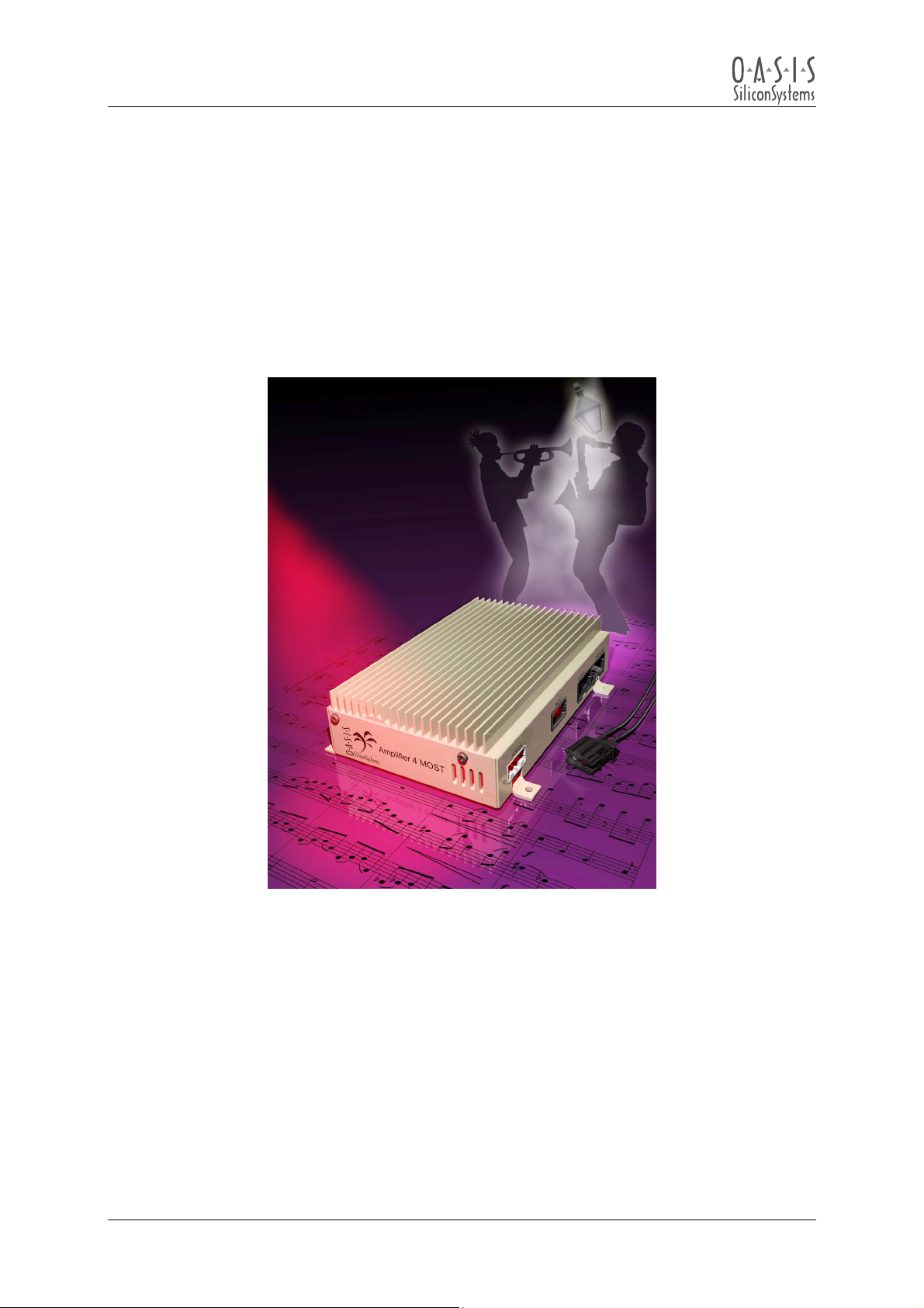
Amplifier 4 MOST
User Manual
Amplifier 4 MOST
© Copyright 2002 - 2003 OASIS SiliconSystems
All rights reserved
MOST is a registered trademark
User Manual
Page 3
© Copyright 2002 - 2003 OASIS SiliconSystems
Amplifier 4 MOST Version: 2.0 User M anual
Document Version: 2.0-03 Release Date: 20 03-07-23
Page 4

Amplifier 4 MOST
User Manual
Document History
Version Date Section Comment on changes
2.0-00 2002-09-02 - First version
2.0-03 2003-07-23
1.2 Change delay mem to optional
5 Remove connection comments from harness dwg
8 Replaced with reference to OS88558 User Manual
User Manual
Page 4
© Copyright 2002 - 2003 OASIS SiliconSystems
Amplifier 4 MOST Version: 2.0 User M anual
Document Version: 2.0-03 Release Date: 20 03-07-23
Page 5

Amplifier 4 MOST
User Manual
Table Of Contents
OVERVIEW .......................................................................................................................................7
1
1.1 Amplifier 4 MOST Contents...........................................................................................................7
1.2 Features.........................................................................................................................................7
1.3 Applications ...................................................................................................................................8
1.4 Reference Data..............................................................................................................................8
1.5 Block Diagram/Typical Application ................................................................................................8
2 FUNCTIONAL DESCRIPTION .........................................................................................................9
3 ELECTRICAL CHARACTERISTICS ............................................................................................. 10
3.1 Operating Conditions.................................................................................................................. 10
3.2 Amplifier Channel Characteristics .............................................................................................. 10
3.3 Microphone Input Characteristics ............................................................................................... 11
3.4 Line Level Input Characteristics ................................................................................................. 11
3.5 Line Level Outputs...................................................................................................................... 12
4 APPLICATION INFORMATION .................................................................................................... 13
4.1 Recommended Equipment ......................................................................................................... 13
4.2 Equipment Setup ........................................................................................................................ 13
4.2.1 Location Of The Connectors ............................................................................................... 13
4.2.2 Power Connections ............................................................................................................. 14
4.2.3 Speaker Connections .......................................................................................................... 14
4.2.4 Line Input Connections........................................................................................................ 14
4.2.5 OptoLyzer4MOST Setup ..................................................................................................... 15
4.2.6 MOST Network Connections............................................................................................... 15
4.3 Basic MOST Network Configuration........................................................................................... 16
4.4 Complete MOST Network Configuration .................................................................................... 18
4.5 S/PDIF MOST Network Configuration ........................................................................................ 20
5 CONNECTOR/CABLE PINOUTS.................................................................................................. 22
6 PHYSICAL DIMENSIONS .............................................................................................................23
7 SOFTWARE CONTROLS (.OCI – FILES) .................................................................................... 25
7.1 Amplifier 4 MOST Control (2V0_MOSTAMP188.oci)................................................................. 25
7.2 MOST Media Player Control (2V0_Media190.oci) ..................................................................... 26
8 FUNCTION BLOCKS..................................................................................................................... 27
9 APPENDIX A: LIST OF FIGURES ................................................................................................ 28
10 APPENDIX B: LIST OF TABLES .............................................................................................. 28
User Manual
Page 5
© Copyright 2002 - 2003 OASIS SiliconSystems
Amplifier 4 MOST Version: 2.0 User M anual
Document Version: 2.0-03 Release Date: 20 03-07-23
Page 6

Amplifier 4 MOST
User Manual
Conventions
Within this manual, the following abbreviations and symbols are used for improving readability:
Comment
PIN
FileName.xxx
FunctionName()
PointerName
BIT Name of a single bit within a register
x..y Range from x to y. Used as abbreviation e.g. for a group of bits like D7..0
[a,b,c] List of alternative elements to choose from.
0xzz Hexadecimal number (value zz)
bREG Single byte (8bit) Register
wREG Single word register (16bit)
mREG Multi byte register (e.g. message buffer)
RSVD The respective bit or register is reserved for future use
/ Inverter
x Don’t care
Ç
È
DAC
ADC
DSP
DBFS
EQ
LSB
MSB
IDS
MNS
NIC
FOT
FOR
AS
FBlock
POF
Name of a PIN
Name of a file
Name of a function
Name of a pointer
Rising edge
Falling edge
Digital to Analog Converter
Analog to Digital Converter
Digital Signal Processor
Decibels relative to digital full scale
Equalizer
Least Significant Bit
Most Significant Bit
Integrated Development System
MOST NetServices
MOST Network Interface Controller
Fiber optical Transceiver (Transmitter & Receiver)
Fiber optical receiver
Application Services
Function Block
Plastic Optical Fiber
User Manual
Page 6
© Copyright 2002 - 2003 OASIS SiliconSystems
Amplifier 4 MOST Version: 2.0 User M anual
Document Version: 2.0-03 Release Date: 20 03-07-23
Page 7

Amplifier 4 MOST
User Manual
1 Overview
This document describes the Amplifier 4 MOST based on the OS88558 Application Specific Media
Processor, and how to set it up to play audio from an analog, digital (S/PDIF), or MOST Media player
source.
Note:
The core functionality is provided by the integrated circuit of OASIS SiliconSystems. This controller is
described in the separate OS88558 user manual.
1.1 Amplifier 4 MOST Contents
The Amplifier 4 MOST includes the following components:
• 1 Amplifier 4 MOST
• 1 speaker cable harness
(Connects “SPEAKERS” socket of the Amplifier 4 MOST to external speakers)
• 1 signal cable harness
(Connects “SIGNAL” socket of the Amplifier 4 MOST to the signal inputs and outputs.)
• 1 power cable harness
(Connects “POWER” socket of the Amplifier 4 MOST to power supply or battery)
• 1 optical connector
(Connects “MOST” socket to a MOST Network
Amplifier side: Yazaki 2+0P connector, MOST side: to HP HFBR-4531 connector, 2 orange
optical fibers, 2x HP HFBR-4505 fiber-fiber-coupler
• 2 plastic optical fibers with HP HFBR-4531 connectors
• 1 CD containing documentation and .oci files to control the Amplifier 4 MOST.
• 1 user manual
1.2 Features
• OS88558-based single-chip amplifier processor
• Optical MOST Network interface
• Built-in Network Management Software
• Basic audio processing: Volume, fade, tone control
• Graphic equalizer
• Dynamic channel compression / limiting
• 128K external delay memory (optional)
• 8 channel power amplifier for external speakers
• Software updateable over the MOST Network
User Manual
Page 7
© Copyright 2002 - 2003 OASIS SiliconSystems
Amplifier 4 MOST Version: 2.0 User M anual
Document Version: 2.0-03 Release Date: 20 03-07-23
Page 8
Amplifier 4 MOST
User Manual
1.3 Applications
The Amplifier 4 MOST is recommended for rapid prototyping of automotive systems, demonstration of
MOST technology and the integrated circuit OS88558.
1.4 Reference Data
• 110 dB effective dynamic range on channels 1 - 4
• Up to 40 W
• Line outputs for two powered speakers (e.g. powered subwoofer system)
• Automotive environmental specifications met
• Stereo Line inputs
• Microphone input
per channel into eight 2 Ω speakers
rms
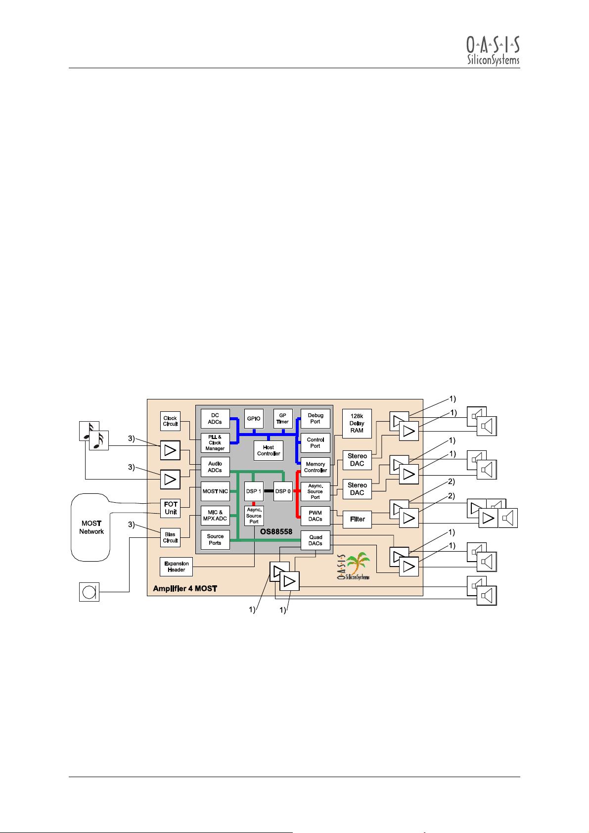
1.5 Block Diagram/Typical Application
Figure 1-1: Block diagram of the Amplifier 4 MOST
1) Power amplifier
2) Line output amplifier
3) Differential input
User Manual
Page 8
© Copyright 2002 - 2003 OASIS SiliconSystems
Amplifier 4 MOST Version: 2.0 User M anual
Document Version: 2.0-03 Release Date: 20 03-07-23
Page 9

Amplifier 4 MOST
User Manual
2 Functional Description
The Amplifier 4 MOST is a demo module that demonstrates the features of the integrated amplifier
controller. The Amplifier 4 MOST is implemented using a single OS88558 amplifier controller to do all
processing necessary to transport audio information between a MOST Network and external
speakers.
The OS88558 amplifier controller includes a MOST Network interface, a microcontroller, 2 DSP’s,
128K of internal FLASH memory, and several A/D and D/A converters. There is a provision for a
stereo analog input and also for an electret microphone.
MOST NetServices software is built into this module providing the software services needed to
communicate with other MOST devices.
The software built into the Amplifier 4 MOST includes digital signal processing for eight audio streams.
In this demo device it is possible to amplify one stereo audio signal (analog or via MOST Network) up
to eight external speakers which can be controlled regarding to Volume, Balance, Fading etcetera.
User Manual
Page 9
© Copyright 2002 - 2003 OASIS SiliconSystems
Amplifier 4 MOST Version: 2.0 User M anual
Document Version: 2.0-03 Release Date: 20 03-07-23
Page 10
Amplifier 4 MOST
User Manual
3 Electrical Characteristics
3.1 Operating Conditions
The Amplifier 4 MOST supports the following operating modes:
“Full on”: Amplifiers provide full amplification
“Idle”: Digital circuits operate with amplifiers muted
“Sleep”: Fiber optic receiver unit active and waiting for light input
The power supply operates normally while the input voltage is between 10 and 16 Volt DC. The
Amplifier 4 MOST will mute on the following fault conditions:
1. Under voltage – input voltage drops below 10 Volt DC
2. Loss of Light – optical input shut off or removed
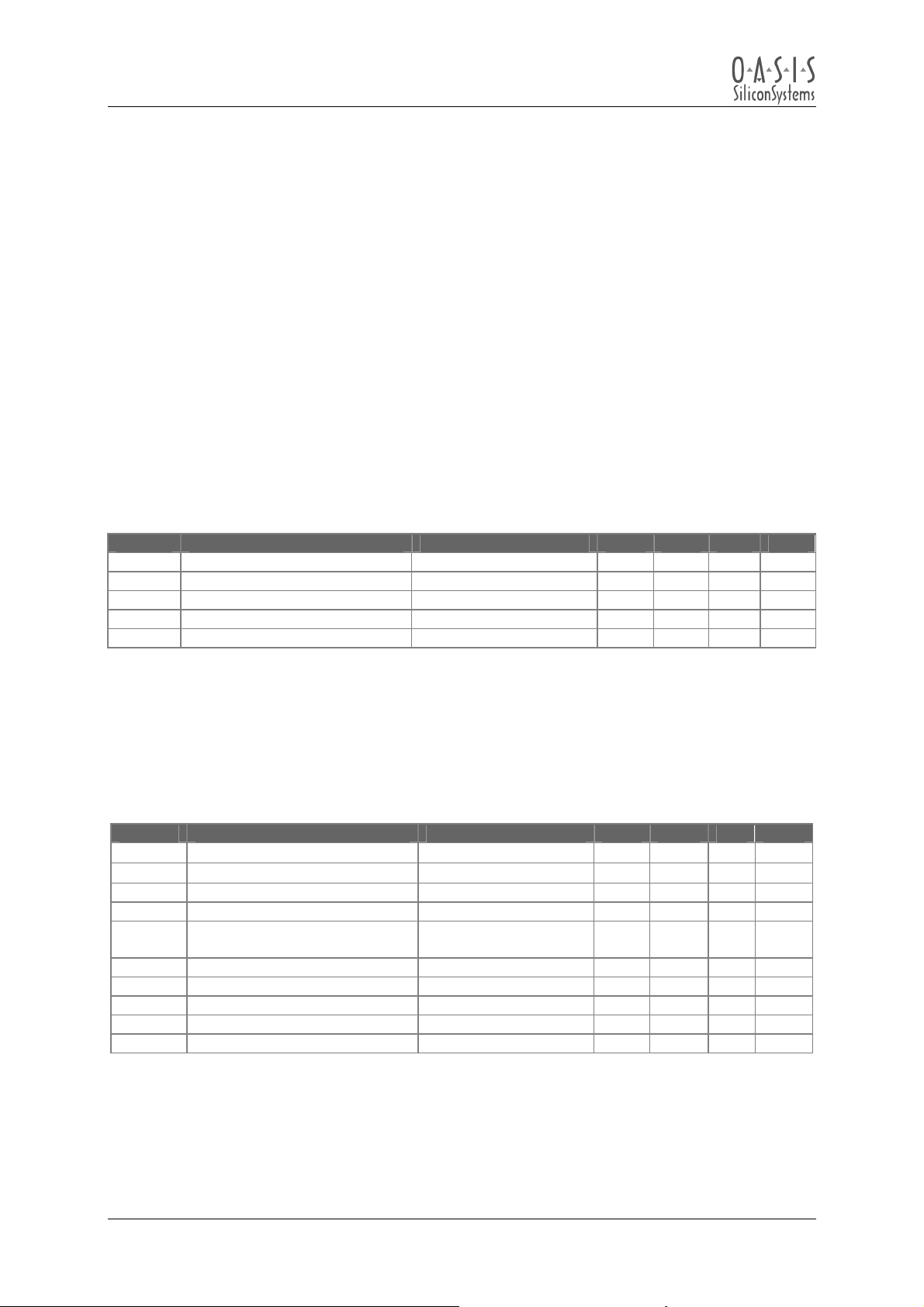
Operating conditions:
Symbol Description Conditions Min Typ Max Units
V
Operating Supply Voltage Full ON operation 10 14.4 18 V
bat
V
Idle Supply Voltage Idle operation 5 10 V
idle
Iq Idle Supply Current Muted 1 A
I
Sleep Supply Current Light off for 1 Min 160 µA
sleep
Ipk Peak Supply Current 40 A
Table 3-1: Operating characteristics
3.2 Amplifier Channel Characteristics
Symbol Description Conditions Min Typ Max Units
P
Output Power
out
R
=4 Ω, THD=10 %
L
R
=2 Ω, THD=10 %
L
THD Volume = 0x40 -85 dB
PSRR Power Supply Rejection -60 dB
DR Dynamic Range Volume=Max vs
Volume=min+1
Vn(0) Output Noise Volume=0x00 200 µV
flo Low frequency cutoff 50 Hz
fhi High Frequency cutoff 20 kHz
Frequency response From flo to fhi -3 0.5 dB
V
Full Scale Output Voltage 8.5 V
ffs
Table 3-2: Amplifier channel characteristics
The amplifiers are short-circuit protected. All tests performed using a 1FFS digital source on the
MOST Network, V
= 14.4 Volt DC, sound settings flat, output signal measured at the output
bat
terminals of the Amplifier 4 MOST.
User Manual
Page 10
© Copyright 2002 - 2003 OASIS SiliconSystems
Amplifier 4 MOST Version: 2.0 User M anual
Document Version: 2.0-03 Release Date: 20 03-07-23
25 W
40 W
110 dB
rms
rms
Page 11
Amplifier 4 MOST
User Manual
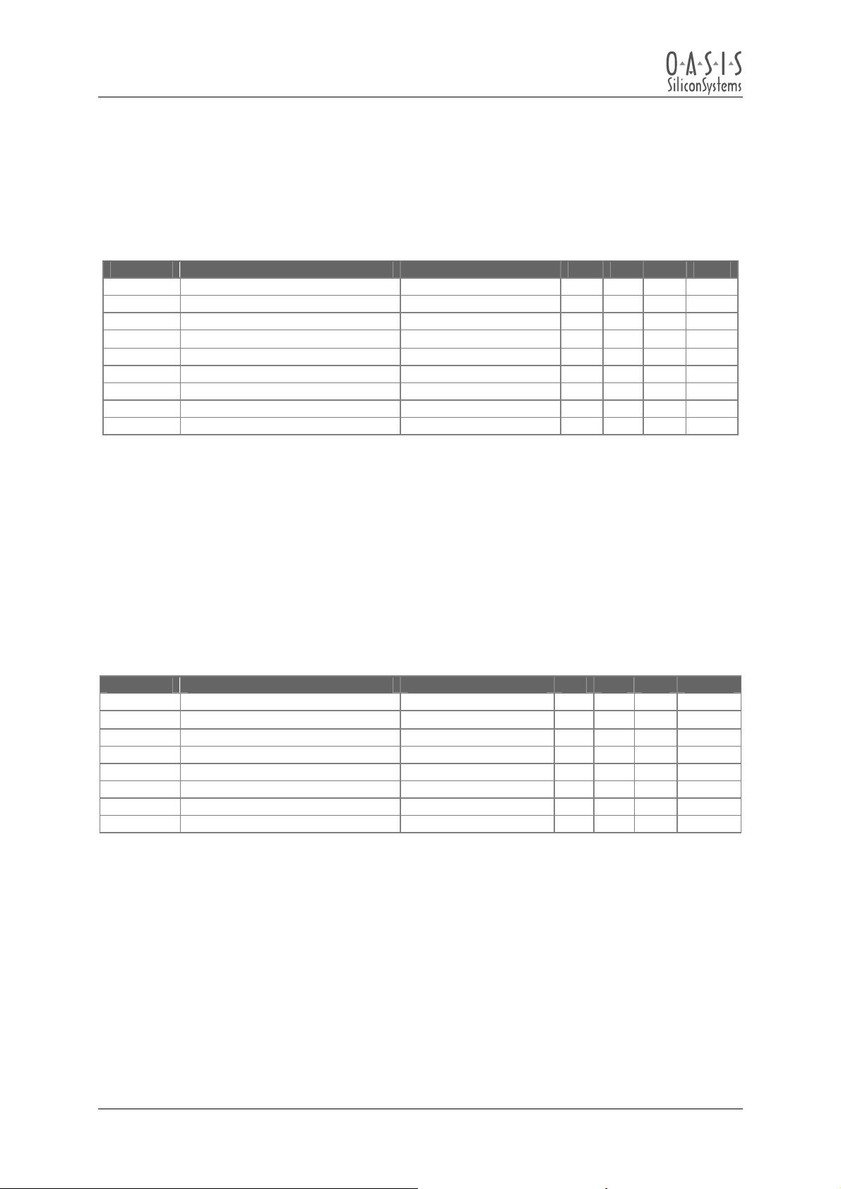
3.3 Microphone Input Characteristics
The microphone input is a differential input with a DC Bias suitable for electret or active microphones.
Microphone input characteristics:
Symbol Description Conditions Min Typ Max Units
V
Microphone Bias Voltage 8.2 V
mbias
I
Microphone Bias Current 5 mA
mic
V
Full Scale Input Voltage 265 mV
mffs
Zin Input Impedance 1
PSRR Power Supply Rejection -60 dB
CMRR Common Mode Rejection -45 dB
flo Low frequency cutoff 5.3 Hz
fhi High Frequency cutoff 4.8 kHz
Frequency response From flo to fhi -3 0.5 dB
1)
Table 3-3: Microphone Input characteristics
rms
kΩ
3.4 Line Level Input Characteristics
The Amplifier 4 MOST includes one set of stereo, line-level analog inputs. These inputs can be used
as audio inputs to the Amplifier 4 MOST.
Line input characteristics:
Symbol Description Conditions Min Typ Max Units
V
Full Scale Input Voltage 440 mV rms
lffs
Zin Input Impedance 10
PSRR Power Supply Rejection -60 dB
CMRR Common Mode Rejection -45 dB
SNR Signal to Noise Ratio 85 dB
flo Low frequency cutoff 1.6 Hz
fhi High Frequency cutoff 20 kHz
Frequency response From 20 Hz to 20 kHz -3 0.5 dB
Table 3-4: Line level input characteristics
kΩ
User Manual
Page 11
© Copyright 2002 - 2003 OASIS SiliconSystems
Amplifier 4 MOST Version: 2.0 User M anual
Document Version: 2.0-03 Release Date: 20 03-07-23
Page 12
Amplifier 4 MOST
User Manual
3.5 Line Level Outputs
The output of the OS88558 PWM DAC’s are passed through a third order active low-pass filter.
These outputs are full range. The output buffers are designed to drive long cables.
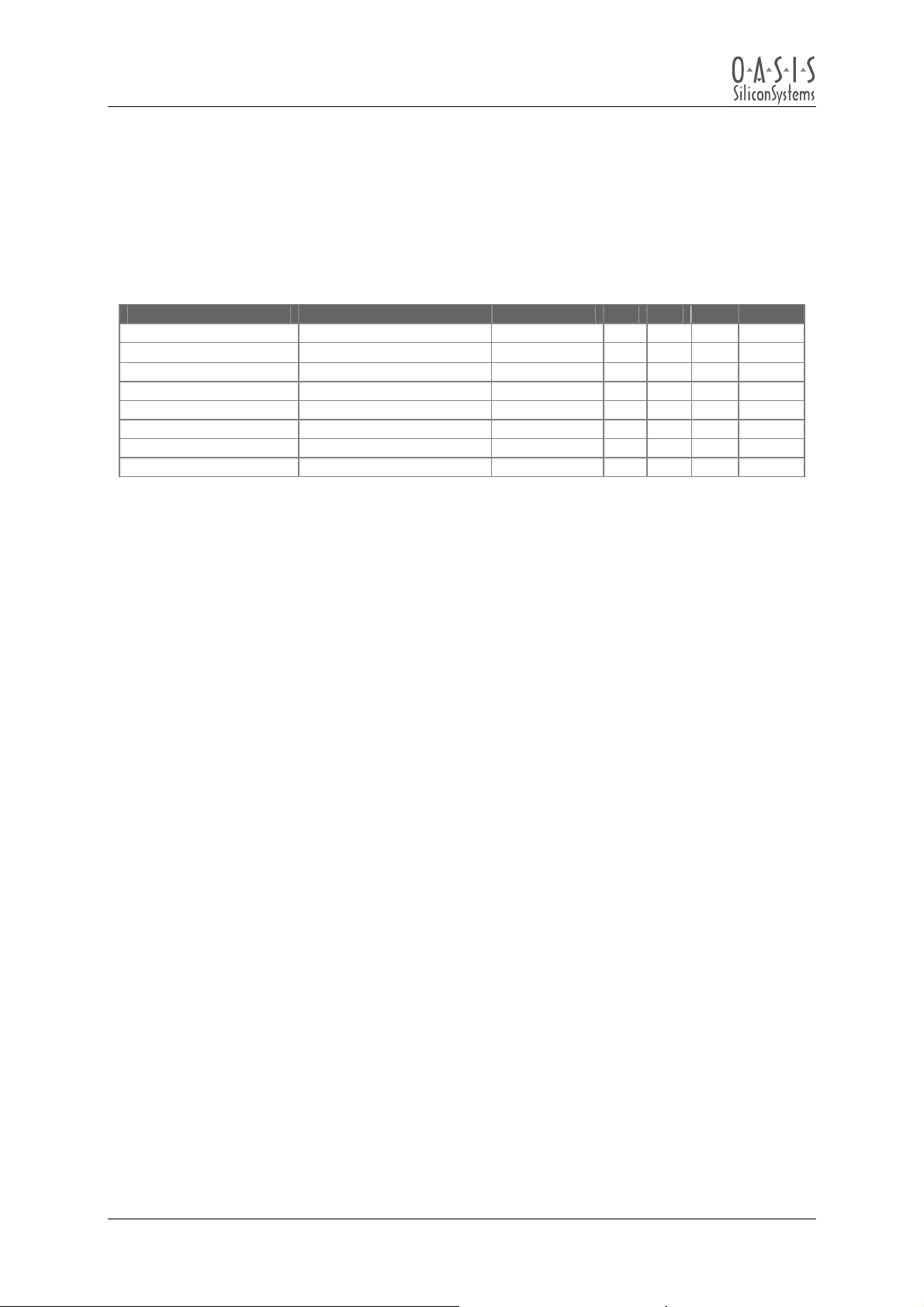
Line Output characteristics:
Symbol Description Conditions Min Typ Max Units
V
Full Scale Output Voltage 800 mVrms
pffs
Z
Output Impedance 700
out
PSRR Power Supply Rejection -50 dB
V(0) Output Noise Volume=0x00 200 µVrms
SNR Signal to Noise Ratio 85 dB
flo Low frequency cutoff 20 Hz
fhi High Frequency cutoff 18 kHz
Frequency response From flo to fhi -3 0.5 dB
1)
Ω
Table 3-5: Line level output characteristics
User Manual
Page 12
© Copyright 2002 - 2003 OASIS SiliconSystems
Amplifier 4 MOST Version: 2.0 User M anual
Document Version: 2.0-03 Release Date: 20 03-07-23
Page 13
Amplifier 4 MOST
User Manual
4 Application Information
4.1 Recommended Equipment
The following sections walk through connection and operation of the Amplifier 4 MOST. It is
recommended for these procedures that the following equipment is available:
• Amplifier 4 MOST
• OptoLyzer4MOST Interface Box with software
• 14.4 Volt DC Power supply capable of delivering at least 15 Ampère DC
• Speakers
• An analog audio source (CD player, MP3 player, etc.)
Optionally the following equipment can be used:
• MOST Media Player or MOST DVD-Player
• An S/PDIF audio source (CD player, or PC with S/PDIF optical outputs) streaming audio data via
an OptoLyzer4MOST Interface Box
4.2 Equipment Setup
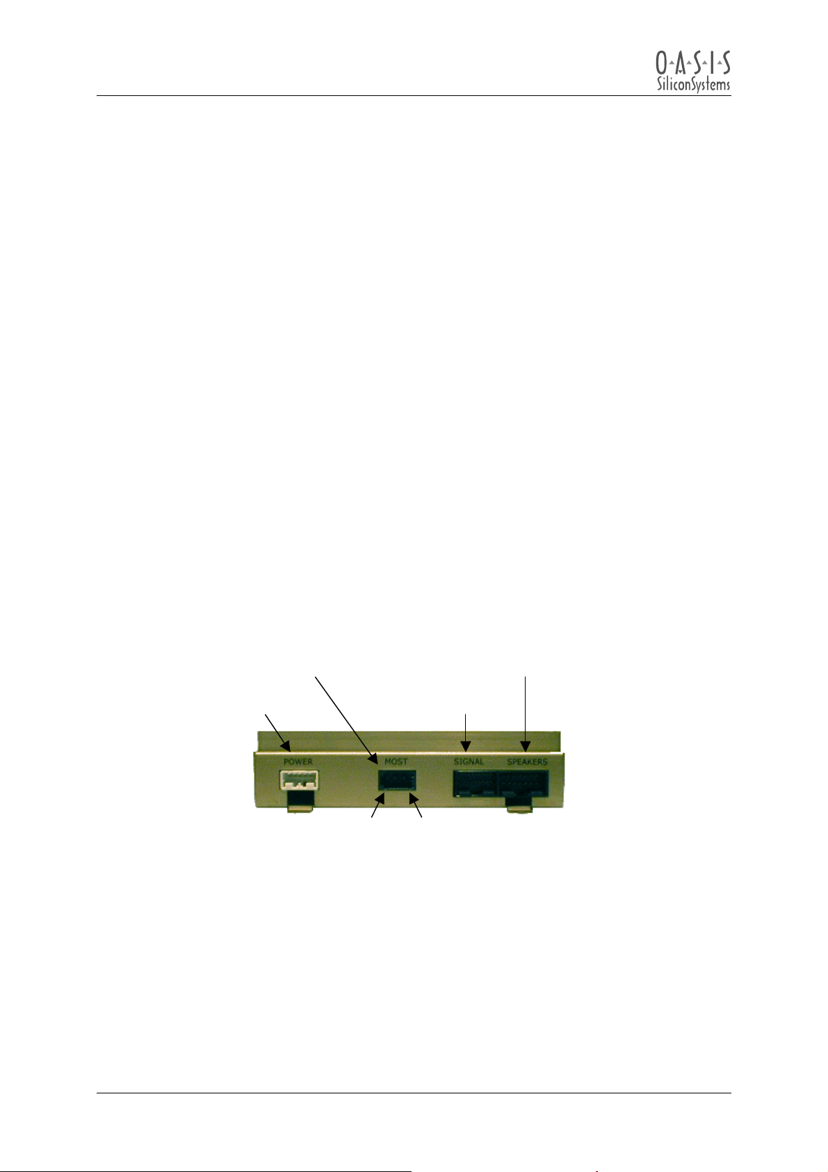
4.2.1 Location Of The Connectors
MOST Network
optical connector
Yazaki 2+0P
Power
Figure 4-1: Location of the connectors
Please refer to section 5 on page 22 for detailed Information about the cable harnesses.
Signal connector
e.g. analog in, etc.
Rx Tx
Speakers connector
for 8 external
speakers (2 Ω )
User Manual
Page 13
© Copyright 2002 - 2003 OASIS SiliconSystems
Amplifier 4 MOST Version: 2.0 User M anual
Document Version: 2.0-03 Release Date: 20 03-07-23
Page 14

Amplifier 4 MOST
User Manual
4.2.2 Power Connections
All components used in this setup, except the PC, are designed to run from a standard car battery.
For laboratory use the battery is replaced by a power supply, set to 14.4 Volt DC with at least 15 Ampère of current.
Note:
The Amplifier 4 MOST can draw as much as 40 Ampère when running with maximum output power to
all channels.
With the power supply off, connect the 6 Pin female connector to “POWER” on the Amplifier 4 MOST.
Connect pins 1-3 to the B+ (+14.4VDC), and pins 4-6 to GND of the supply. Connect the
OptoLyzer4MOST Interface Box’s power plug. If a MOST Media Player is used, attach its power cable
as well. For convenience all devices may be connected together and plugged into one power supply,
or if desired, each component from it’s own supply. Leave the power off for now.
4.2.3 Speaker Connections
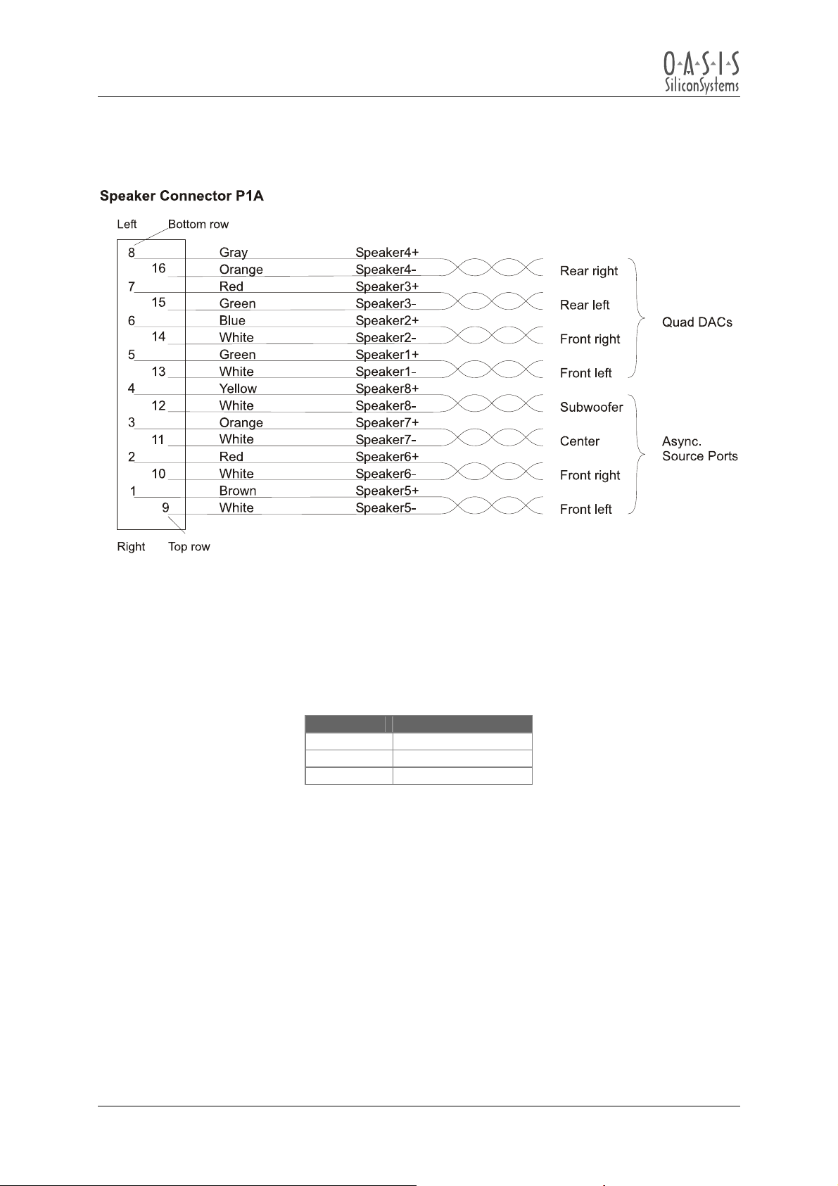
Connect the speakers to the Amplifier 4 MOST. Section 5 (Connector/Cable Pinouts) shows the pin
out of all connectors on the Amplifier 4 MOST, and its respective cable. If this is the first time using
the Amplifier 4 MOST, connect the included speaker cable harness to the Amplifier 4 MOST, and
attach the blue and white twisted pair to one speaker, and the green and white twisted pair to another
speaker. There are 8 channels of power amplification available. Each channel can drive impedances
as low as 2 Ω, however care should be taken to avoid an overall power output greater than 250 W
For being able to use the Fader feature, a second pair of speakers must be connected to a pair of
outputs labeled “Rear” as shown in section
Note:
For power levels greater than 250 W forced air and / or additional heat-sinking of the Amplifier 4
MOST is recommended.
5.
rms
4.2.4 Line Input Connections
A stereo audio input is available on the Amplifier 4 MOST. This input is recommend for use with
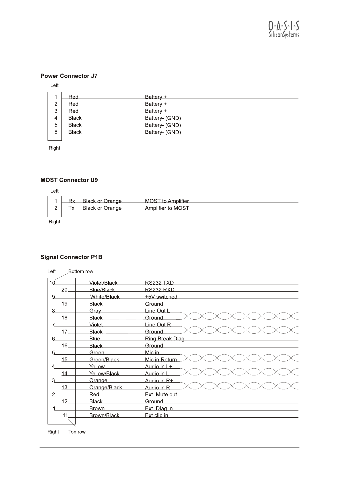
external analog sources. These pins are available on “SIGNAL” socket, Pins 3 & 13 for left channel,
Pins 4 & 14 for right channel analog input. Attach a suitable connector to these wires and connect to
an analog audio source.
.
User Manual
Page 14
© Copyright 2002 - 2003 OASIS SiliconSystems
Amplifier 4 MOST Version: 2.0 User M anual
Document Version: 2.0-03 Release Date: 20 03-07-23
Page 15

Amplifier 4 MOST
User Manual
4.2.5 OptoLyzer4MOST Setup
Connect a standard serial cable between the OptoLyzer4MOST Interface Box and the computer’s
COM port. If the OptoLyzer4MOST was not used before, install the software and associated license
codes. Refer to the OptoLyzer4MOST manual for details. Several specific files are included on the
Amplifier 4 MOST control disk. It is recommended to copy the directory “\control” from the CD to the
hard drive of the PC. The path to this folder will be referenced as “Amp_Control_path” in the
application examples (Section
be found in this directory as well as a SyntaxTree file (.pbn). These files are to be loaded to the
OptoLyzer4MOST Standard or Professional software edition to control the Amplifier 4 MOST via an
OptoLyzer4MOST Interface Box connected to the PC using a standard serial RS232 cable connection.
4.2.6 MOST Network Connections
Now make the network connections to form a MOST Network using the optical cables provided. The
connector of the orange dual optical cable plugs into “MOST” on the Amplifier 4 MOST (Remove the
white socket-protection-cover first).
Connect the Rx (left) of the Amplifier 4 MOST to Tx of the OptoLyzer4MOST Interface Box.
Connect the Tx (right) of the Amplifier 4 MOST to Rx of the OptoLyzer4MOST Interface Box.
If an OptoLyzer4MOST Interface Box version “V5” with Yazaki sockets is used connect the another
POF using the provided couplers between the cables.
4.3 to 4.5). The RemoteControl files (.oci) described in section 7 can
User Manual
Page 15
© Copyright 2002 - 2003 OASIS SiliconSystems
Amplifier 4 MOST Version: 2.0 User M anual
Document Version: 2.0-03 Release Date: 20 03-07-23
Page 16
Amplifier 4 MOST
User Manual
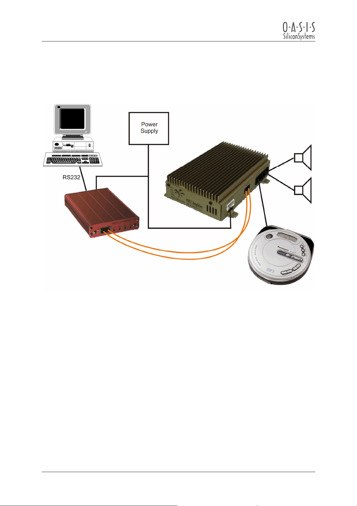
4.3 Basic MOST Network Configuration
Amplifier 4 MOST & OptoLyzer4MOST Interface Box:
Figure 4-2: Basic MOST Network configuration
User Manual
Page 16
© Copyright 2002 - 2003 OASIS SiliconSystems
Amplifier 4 MOST Version: 2.0 User M anual
Document Version: 2.0-03 Release Date: 20 03-07-23
Page 17

Amplifier 4 MOST
User Manual
In this configuration an analog input signal is played through the Amplifier 4 MOST. The
OptoLyzer4MOST and the MOST Network are used only for controlling the Amplifier 4 MOST. The
following walk through describes how to play audio through the Amplifier 4 MOST using the
OptoLyzer4MOST Standard software. Section
RemoteControl used below.
1. Build a MOST Network as shown in
Figure 4-2 and described in section 4.2.
2. Apply power to all the components in the MOST Network, and flip the power switch on the
back of the OptoLyzer4MOST Interface Box to ON.
3. Switch on the PC (if its not already running).
4. Press play on the audio source (or make sure there is a proper audio signal at the audio input
of the Amplifier 4 MOST).
5. Run the OptoLyzer4MOST Standard software installed on the PC.
6. Go to the OptoLyzer4MOST Standard software’s task-bar and click on the “Mode” button.
7. Under the “Connection Type” tab, select “Master Mode” and click “Accept”.
8. The green lock light of the OptoLyzer4MOST Interface Box should now be lit. If not, check
power connections, and check for each MOST TX fiber to be connected to the RX fiber of the
other device.
9. Click on the OptoLyzer4MOST Standard software’s “Viewer” button to bring up the
OptoViewer Window.
10. Go to the OptoLyzer4MOST Standard software’s task-bar and click on the “Control” button.
An “OptoControl” window will open.
11. Click on the button, with the little arrow pointing downwards, to the right of the “Customize”
button. Click on “Load Profile” in the menu that pops up.
12. In the “Amp_Control_path” (described in section
“2V0_MOSTAMP188.oci” file. Then click the “Open” button. A remote control interface
window will be opened in the “OptoControl” window.
13. Click the “Notification” button and verify that 6 Amplifier 4 MOST status messages are
displayed in the OptoViewer window. This makes sure that the Amplifier 4 MOST is ready and
communicates properly with the OptoLyzer4MOST Interface Box and its software.
14. In the OptoControl 2V0_MOSTAMP188.oci window click “Connect ADC”.
15. In the OptoControl 2V0_MOSTAMP188.oci window click the button “3” under the “Volume”
label.
16. In the OptoControl 2V0_MOSTAMP188.oci window click DeMute.
Audio should now be played through the speakers. The volume can be changed in small steps by
means of the “Increment” (Arrow up) and “Decrement” (Arrow down) buttons, or in large steps by
pressing one of the six volume buttons. While “0” represents the lowest volume level, “5” stands for
the maximum volume (caution). If no audio is heard, check the source connections, and make sure
that the audio source is playing.
There are a number of buttons on the 2V0_MOSTAMP188.oci control panel. They can be adjusted
now freely.
7.1 helps to locate the different buttons of the
4.2.5) select the “oci” subfolder and then the
User Manual
Page 17
© Copyright 2002 - 2003 OASIS SiliconSystems
Amplifier 4 MOST Version: 2.0 User M anual
Document Version: 2.0-03 Release Date: 20 03-07-23
Page 18
Amplifier 4 MOST
User Manual
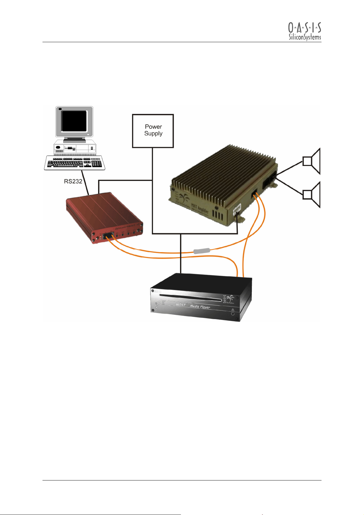
4.4 Complete MOST Network Configuration
Amplifier 4 MOST, MOST Media Player & OptoLyzer4MOST Interface Box:
Figure 4-3: Complete MOST Network configuration
User Manual
Page 18
© Copyright 2002 - 2003 OASIS SiliconSystems
Amplifier 4 MOST Version: 2.0 User M anual
Document Version: 2.0-03 Release Date: 20 03-07-23
Page 19

Amplifier 4 MOST
User Manual
Once the Amplifier 4 MOST is working in the basic MOST Network configuration as described in
section
Player is used as a digital audio source. Audio data is transported over the MOST Network. The
OptoLyzer4MOST Interface Box is used for controlling both, the Amplifier 4 MOST and the MOST
Media Player. Section
Audio should now be played through the speakers. The volume can be changed in small steps by
means of the “Increment” (Arrow up) and “Decrement” (Arrow down) buttons, or in large steps by
pressing one of the six volume buttons. While “0” represents the lowest volume level, “5” stands for
the maximum volume (caution). If no audio is heard, check the source connections, and make sure
that the audio source is playing.
4.3, it is possible to add a digital audio source. In this configuration example the MOST Media
7 helps to locate the different buttons of the RemoteControls used below.
1. Break the MOST Network described in the basic setup and insert the MOST Media Player
using the optical cables supplied as shown in
Figure 4-3.
2. Connect the MOST Media Player power into the DC power supply.
3. Apply power to all the components in the MOST Network, and flip the power switch on the
back of the OptoLyzer4MOST Interface Box ON.
4. Switch on the PC and run the OptoLyzer4MOST Standard software installed on it.
5. Go to the OptoLyzer4MOST Standard software’s task-bar and click on the “Mode” button.
6. Under the “Connection Type” tab, select “Master Mode” and click “Accept”.
7. The green lock light of the OptoLyzer4MOST Interface Box should now be lit. If it is not, check
power connections, and check for each MOST TX fiber to be connected to the RX fiber of the
next device.
8. Click on the OptoLyzer4MOST Standard software’s “Viewer” button to bring up the
OptoViewer Window.
9. Go to the OptoLyzer4MOST Standard software’s task-bar and click on the “Control” button.
An “OptoControl” window will open.
10. Click on the button, with the little arrow pointing downwards, to the right of the “Customize”
button. Click on “Load Profile” in the menu that pops up.
11. In the “Amp_Control_path” (described in section
4.2.5) select the “oci” subfolder and then the
“2V0_MOSTAMP188.oci” file. Then click the “Open” button. A remote control interface
window will be opened in the “OptoControl” window.
12. Click the “Notification” button and verify that 6 Amplifier 4 MOST status messages are
displayed in the OptoViewer window. This makes sure that the Amplifier 4 MOST is ready and
communicates properly with the OptoLyzer4MOST Interface Box and its software.
13. Go to the OptoLyzer4MOST Standard software’s task-bar and click on the “Control” button.
An “OptoControl” window will open.
14. Click on the button, with the little arrow pointing downwards, to the right of the “Customize”
button. Click on “Load Profile” in the menu that pops up.
15. In the “Amp_Control_path” (described in section
4.2.5) select the “oci” subfolder and then the
“2V0_Media190.oci” file. Then click the “Open” button. A remote control interface window will
be opened in the “OptoControl” window.
16. In the OptoControl 2V0_Media190.oci window click “Allocate”.
17. Insert a CD in the Media player.
18. In the OptoControl 2V0_Media190.oci window click the play button. The MOST Media Player
will start sending TimeStatus Messages that can be seen in the “Viewer“ window. This is a
normal behavior.
19. In the OptoControl 2V0_MOSTAMP188.oci window click “Connect 00-03”.
20. In the OptoControl 2V0_MOSTAMP188.oci window click the button “3” under the “Volume”
label.
21. In the OptoControl 2V0_MOSTAMP188.oci window click DeMute.
User Manual
Page 19
© Copyright 2002 - 2003 OASIS SiliconSystems
Amplifier 4 MOST Version: 2.0 User M anual
Document Version: 2.0-03 Release Date: 20 03-07-23
Page 20
Amplifier 4 MOST
User Manual
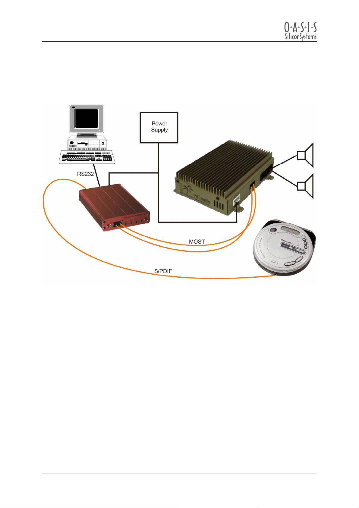
4.5 S/PDIF MOST Network Configuration
Amplifier 4 MOST & OptoLyzer4MOST with S/PDIF source:
Figure 4-4: S/PDIF MOST Network configuration
User Manual
Page 20
© Copyright 2002 - 2003 OASIS SiliconSystems
Amplifier 4 MOST Version: 2.0 User M anual
Document Version: 2.0-03 Release Date: 20 03-07-23
Page 21

Amplifier 4 MOST
User Manual
In this configuration the OptoLyzer4MOST Interface Box synchronizes the entire MOST Network to an
external S/PDIF audio source. The S/PDIF audio data is transported over the MOST Network to the
Amplifier 4 MOST. The OptoLyzer4MOST Interface Box is used for controlling the Amplifier 4 MOST.
Section
Note:
Many S/PDIF sources will clock in “play” mode only.
Audio should now be played through the speakers. The volume can be changed in small steps by
means of the “Increment” (Arrow up) and “Decrement” (Arrow down) buttons, or in large steps by
pressing one of the six Volume buttons. While “0” represents the lowest volume level, “5” stands for
the maximum volume (caution). If no audio is heard, check the source connections, and make sure
that the audio source is playing.
7.1 helps to locate the different buttons of the RemoteControl used below.
1. Begin with the basic MOST Network configuration setup as described in section
4.3.
2. Connect a PCM digital audio source output to the “S/PDIF IN” jack located on the back of the
OptoLyzer4MOST Interface Box using a standard TOSLINK cable as shown in
Figure 4-4.
3. Apply power to all the components in the MOST Network, and flip the power switch on the
back of the OptoLyzer4MOST Interface Box ON.
4. Press play on the audio source to make sure that a proper S/PDIF signal is provided.
5. Switch on the PC and run the OptoLyzer4MOST Standard software installed on it.
6. Go to the OptoLyzer4MOST Standard software’s task-bar and click on the “Mode” button.
7. Under the “Connection Type” tab, select “S/PDIF Master Mode” and click “Accept”.
8. The green lock light of the OptoLyzer4MOST Interface Box should now be lit. If it is not, check
power connections, and check for each MOST TX fiber to be connected to the RX fiber of the
other device. Also check to be sure that the S/PDIF source is playing.
9. Click on the OptoLyzer4MOST Standard software’s “Viewer” button to bring up the
OptoViewer Window.
10. Go to the OptoLyzer4MOST Standard software’s task-bar and click on the “Control” button.
An “OptoControl” window will open.
11. Click on the button, with the little arrow pointing downwards, to the right of the “Customize”
button. Click on “Load Profile” in the menu that pops up.
12. In the “Amp_Control_path” (described in section
4.2.5) select the “oci” subfolder and then the
“2V0_MOSTAMP188.oci” file. Then click the “Open” button. A remote control interface
window will be opened in the “OptoControl” window.
13. Click the “Notification” button and verify that 6 Amplifier 4 MOST status messages are
displayed in the OptoViewer window. This makes sure that the Amplifier 4 MOST is ready and
communicates properly with the OptoLyzer4MOST Interface Box and its software.
14. Go to the OptoLyzer4MOST Standard software’s task-bar and click on the “Source” button.
15. Select the “Allocation” tab. Under the “S/PDIF Input” label click the “Allocate & Connect”
button.
16. In the OptoControl 2V0_MOSTAMP188.oci window click “Connect 00-03”.
17. In the OptoControl 2V0_MOSTAMP188.oci window click the button “3” under the “Volume”
label.
18. In the OptoControl 2V0_MOSTAMP188.oci window click DeMute.
User Manual
Page 21
© Copyright 2002 - 2003 OASIS SiliconSystems
Amplifier 4 MOST Version: 2.0 User M anual
Document Version: 2.0-03 Release Date: 20 03-07-23
Page 22
Amplifier 4 MOST
User Manual
5 Connector/Cable Pinouts
Figure 5-1: Power connector pinouts
Figure 5-2: MOST connector
Figure 5-3: Signal connector pinouts
User Manual
Page 22
© Copyright 2002 - 2003 OASIS SiliconSystems
Amplifier 4 MOST Version: 2.0 User M anual
Document Version: 2.0-03 Release Date: 20 03-07-23
Page 23
Amplifier 4 MOST
User Manual
Figure 5-4: Speaker connector pinouts
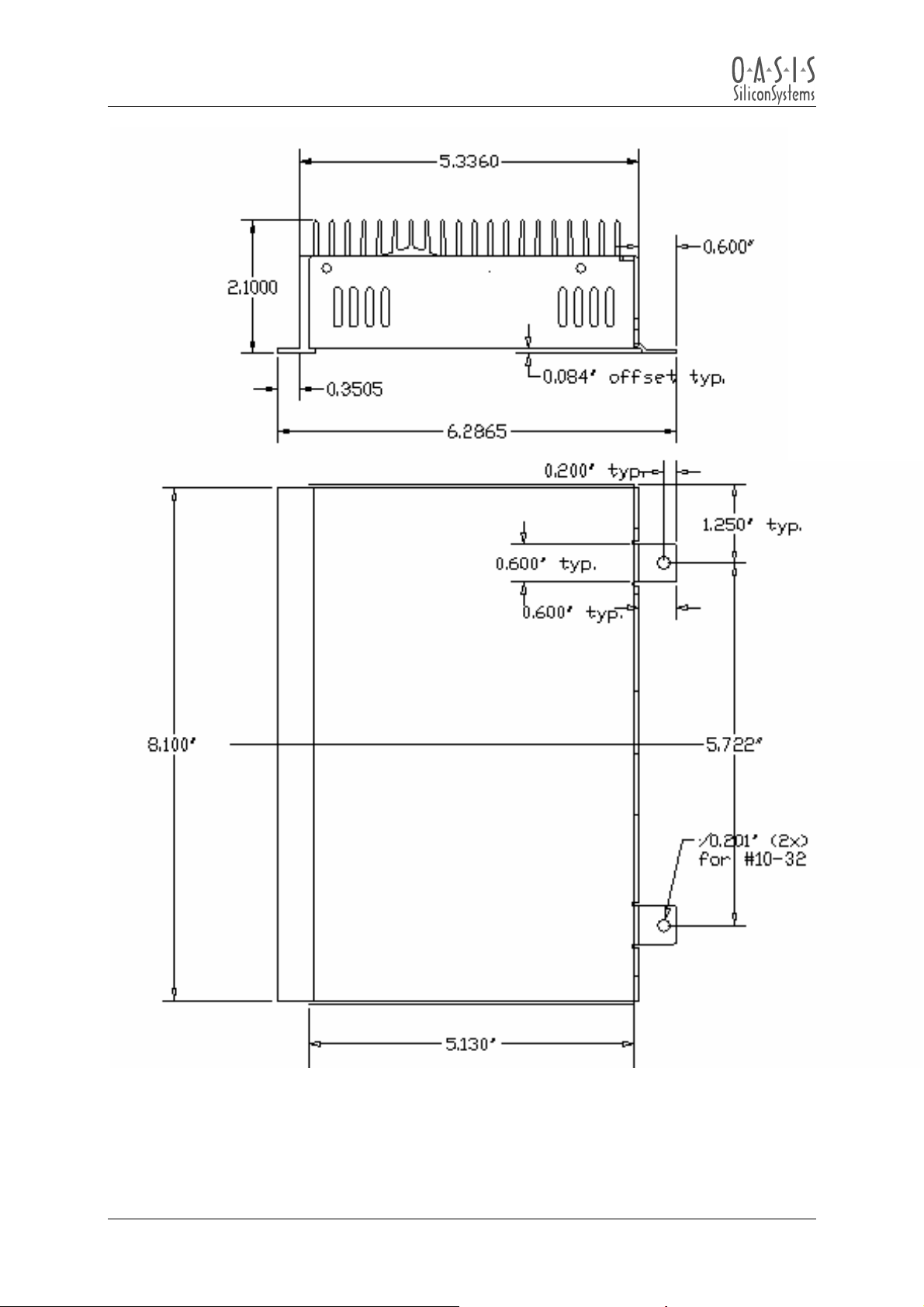
6 Physical Dimensions
Dimensions
Length 8.4252 (214 mm)
Width 6.2598 (159 mm)
Height 2.0866 (53 mm)
Table 6-1: Overall dimensions
User Manual
Page 23
© Copyright 2002 - 2003 OASIS SiliconSystems
Amplifier 4 MOST Version: 2.0 User M anual
Document Version: 2.0-03 Release Date: 20 03-07-23
Page 24
Amplifier 4 MOST
User Manual
Note:
All given dimensions are in inches. (1” (inch) = 25,4 mm)
Figure 6-1: Physical dimensions of the Amplifier 4 MOST
User Manual
Page 24
© Copyright 2002 - 2003 OASIS SiliconSystems
Amplifier 4 MOST Version: 2.0 User M anual
Document Version: 2.0-03 Release Date: 20 03-07-23
Page 25
t
t
t
p
Amplifier 4 MOST
User Manual
7 Software Controls (.oci – Files)
7.1 Amplifier 4 MOST control (2V0_MOSTAMP188.oci)
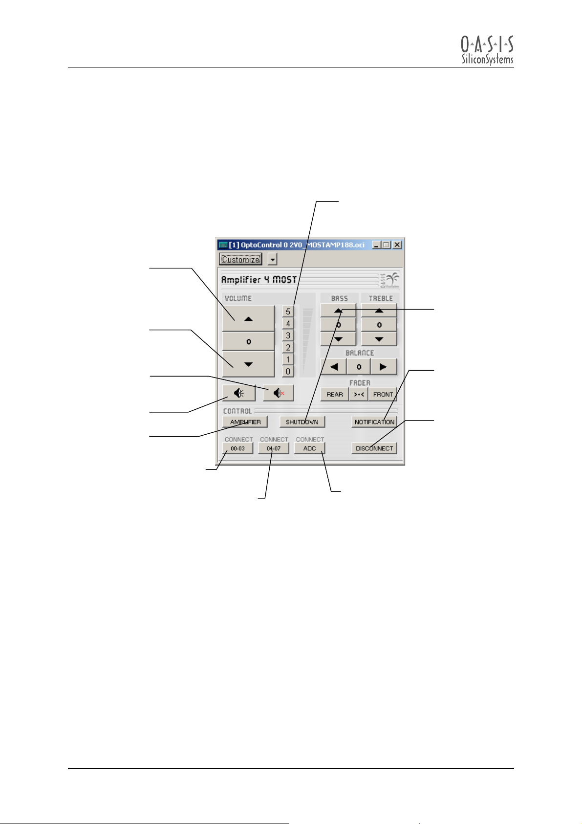
The control file 2V0_MOSTAMP188.oci for the Amplifier 4 MOST looks like this:
Set volume
in six steps
Incremen
volume
Indicates
Decremen
volume
Mute
DeMute
No effec
Connects MOST Bytes
00-03 to the stereo input
Connects MOST Bytes 04-07
to the stereo in
Installation and usage of this control is described in the configuration examples of section 4.3 up to
4.5.
ut
Figure 7-1: Amplifier 4 MOST control
Connects line input signals to the
stereo input
that a shut
down is
pending
Enables
Notification
Service
Removes
current
connection
from the
stereo input
User Manual
Page 25
© Copyright 2002 - 2003 OASIS SiliconSystems
Amplifier 4 MOST Version: 2.0 User M anual
Document Version: 2.0-03 Release Date: 20 03-07-23
Page 26
Amplifier 4 MOST
User Manual
7.2 MOST Media Player Control (2V0_Media190.oci)
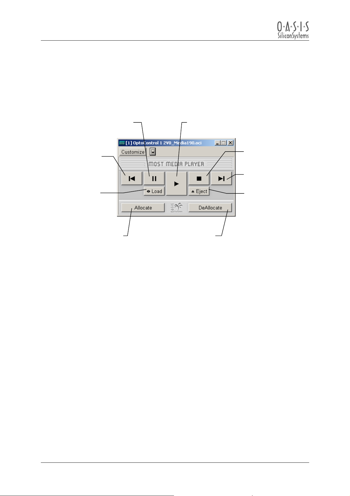
The control file 2V0_Media190.oci for the MOST Media Player looks like this:
Pause playing Play
Track back
Stop playing
Track forward
Load CD
Allocate 4
Channels
DeAllocate
Channels
Figure 7-2: MOST Media Player control
Eject CD
Installation and usage of this control is described in the configuration example in section
4.4.
User Manual
Page 26
© Copyright 2002 - 2003 OASIS SiliconSystems
Amplifier 4 MOST Version: 2.0 User M anual
Document Version: 2.0-03 Release Date: 20 03-07-23
Page 27

Amplifier 4 MOST
User Manual
8 Function Blocks
The Amplifier 4 MOST firmware implements all function blocks as defined in the OASIS
SiliconSystems IC OS88558 user manual. Features related to EEPROM and delay SRAM are
enabled only if these optional devices are detected by the firmware.
User Manual
Page 27
© Copyright 2002 - 2003 OASIS SiliconSystems
Amplifier 4 MOST Version: 2.0 User M anual
Document Version: 2.0-03 Release Date: 20 03-07-23
Page 28

Amplifier 4 MOST
User Manual
9 Appendix A: List Of Figures
Figure 1-1: Block diagram of the Amplifier 4 MOST................................................................................ 8
Figure 4-1: Location of the connectors.................................................................................................. 13
Figure 4-2: Basic MOST Network Configuration ................................................................................... 16
Figure 4-3: Complete MOST Network Configuration ............................................................................ 18
Figure 4-4: S/PDIF MOST Network Configuration ................................................................................ 20
Figure 5-1: Cable pinouts ...................................................................................................................... 22
Figure 6-1: Physical dimensions of the Amplifier 4 MOST.................................................................... 24
Figure 7-1: Amplifier 4 MOST control.................................................................................................... 25
Figure 7-2: MOST Media Player control................................................................................................ 26
10 Appendix B: List Of Tables
Table 3-1: Operating characteristics ..................................................................................................... 10
Table 3-2: Amplifier channel characteristics.......................................................................................... 10
Table 3-3: Microphone Input characteristics ......................................................................................... 11
Table 3-4: Line level input characteristics ............................................................................................. 11
Table 3-5: Line level output characteristics ........................................................................................... 12
Table 6-1: Overall dimensions............................................................................................................... 23
User Manual
Page 28
© Copyright 2002 - 2003 OASIS SiliconSystems
Amplifier 4 MOST Version: 2.0 User M anual
Document Version: 2.0-03 Release Date: 20 03-07-23
 Loading...