

Page 1
PondoVac 5
Page 2
- -
A
B
PVC0018
PVC0019
2
Page 3
C D
- -
E
PVC0021 PVC0022
PVC0023
3
Page 4
- -
F
G
H
PVC0025
PVC0020
PVC0024
4
Page 5
K
I
J
- -
PVC0026
PVC0029 PVC0027
5
Page 6
- -
L
M
PVC0028
PVC0030
6
Page 7

- EN -
- EN -
Translation of the original Operating Instructions
Information about these operating instructions
Welcome to OASE Living Water. You made a good choice with the purchase of this product PondoVac 5.
Prior to commissioning the unit, please read the instructions of use carefully and fully familiarise yourself with the unit.
Ensure that all work on and with this unit is only carried out in accordance with these instructions.
Adhere to the safety information for the correct and safe use of the unit.
Keep these instructions in a safe place! Please also hand over the instructions when passing the unit on to a new
owner.
Symbols used in these instructions
GB
The symbols used in this operating manual have the following meanings:
Risk of injury to persons due to dangerous electrical voltage
This symbol indicates an imminent danger, which can lead to death or severe injuries if the appropriate
measures are not taken.
Risk of personal injury caused by a general source of danger
This symbol indicates an imminent danger, which can lead to death or severe injuries if the appropriate
measures are not taken.
Important information for trouble-free operation.
A Reference to one or more figures. In this example: Reference to Fig. A.
Reference to another section.
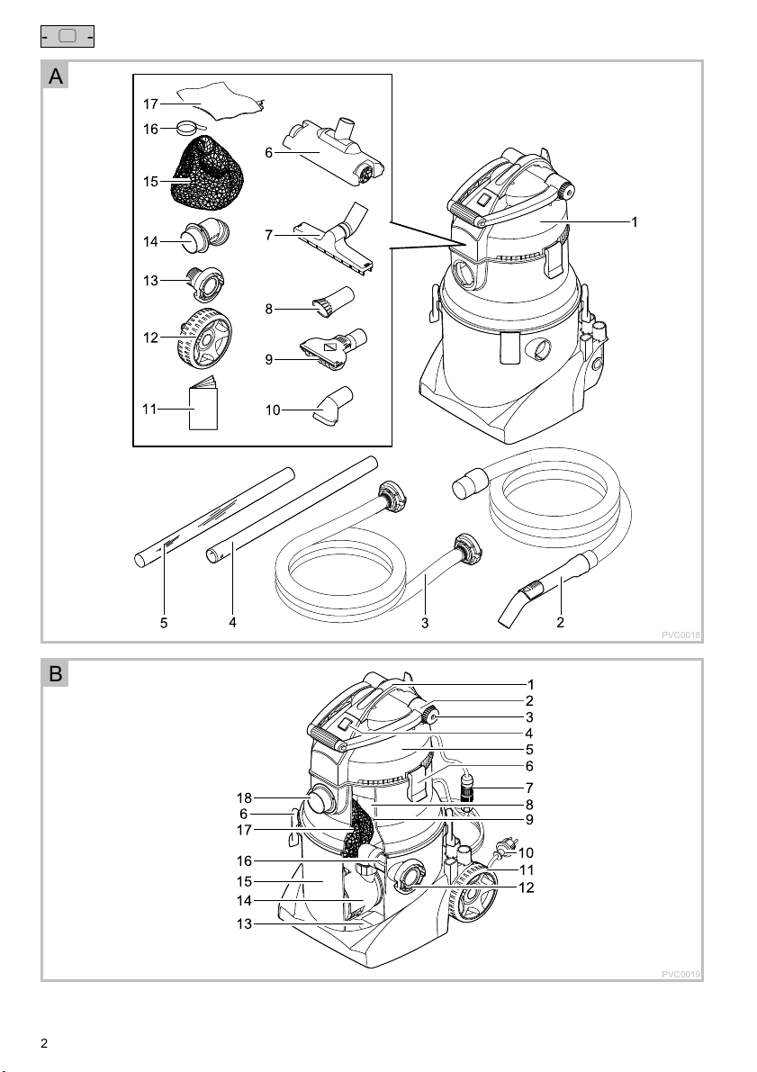
Scope of delivery
The parts included in the scope of delivery are inside the container and have to be removed first!
A
Quantity Description
1 1 Multi-purpose vacuum cleaner PondoVac 5
2 1 Suction hose with handle
3 1 Discharge hose
4 1 Extension tube
5 1 Extension tube, transparent
6 1 Surface cleaning nozzle
7 1 Wet suction nozzle
8 1 Algae nozzle
9 1 Universal nozzle
10 1 Brush nozzle:
For cleaning large, smooth surfaces
For removing dirty or residual water for operation as a wet vacuum cleaner
For separating and removing string algae
For removing pond sludge without vacuuming up the pond gravel
For removing stubborn dirt
11 1 Operating instructions
12 2 Wheel
13 1 Storz coupling type C
14 1 Intake distributor
15 1 Debris collection bag
16 1 Velcro tape for debris collection bag
17 1 Fine filter bag
16
Page 8

- EN -
Product Description
PondoVac 5 is a multi-purpose vacuum cleaner for cleaning garden ponds, pools and swimming ponds. It is also suita-
ble for use as a wet vacuum cleaner in the home.
Unit configuration
Function description
The vacuum cleaner is used for removing sludge from ponds/pools via the suction hose and collecting it in the tank.
The suction power can be regulated with the slide in the suction hose handle.
The debris collection bag in the vacuum cleaner tank collects coarse particles, thereby preventing the discharge pump
from becoming clogged. Should the suction capacity decrease, it is necessary to clean the debris collection bag.
The discharge pump continuously pumps the dirty water out of the tank via the discharge hose.
The float in the filter support basket protects the vacuum head from the ingress of water. Clean the foam filter regularly
to ensure perfect function of the vacuum cleaner. Ensure that the float can move freely.
Protective function of the float:
If the dirty water level in the tank rises inadmissibly, the float closes the intake in the vacuum head and switches the
Intended use
PondoVac 5, referred to in the following as "unit", may only be used as specified in the following:
For pond sludge removal.
For cleaning ponds, swimming ponds and pools.
Only operate the vacuum cleaner with the debris collection bag in place.
Operation under observance of the technical data.
Do not use for commercial or industrial purposes.
Description
B
1 Transport handle
2 Transport brace
3 Locking screw for fastening the transport brace
4 Power switch
For switching the vacuum cleaner on and off
5 Vacuum head
6 Locking clips (6 ×)
7 Plug connector (designed to prevent misconnection) for connecting the pump
8 Foam filter
Protects the electronics in the vacuum head from the ingress of dirt particles.
9 Filter support basket
The integrated float protects the electronics from the ingress of water if the maximum water level is exceeded.
10 Power cable with power plug
11 Wheel (2×)
12 Outlet (pressure socket) with Storz coupling type C
13 Pump base
14 Discharge pump
15 Tank
16 Adapter with non-return valve
The non-return valve prevents water running back via the discharge hose.
17 Debris collection bag
18 Inlet (suction socket)
vacuum head off.
– If the float unblocks the intake within 15 s, the vacuum head will switch on automatically. Otherwise the vacuum
cleaner will switch off completely and a warning signal will sound.
– If the float closes the intake three times within 60 s, the vacuum cleaner will switch off completely and a warning
signal will sound.
– The vacuum cleaner may only be restarted by switching it off and on after remedy of the malfunction.
17
Page 9

- EN -
The following restrictions apply to the unit:
Never run the unit without water.
The debris/dirt must contain at least 20 % water.
Only operate with water at a water temperature of +4 °C to +35 °C.
Never use the unit to convey fluids other than water.
Do not use as a dry vacuum cleaner.
Do not use in conjunction with chemicals, foodstuff, easily flammable or explosive substances.
Do not transport the vacuum cleaner when it is filled.
Safety information
This unit can be used by children from the age of 8 and by persons
with physical, sensory or mental impairments or lack of experience
and knowledge, as long as they are supervised or instructed on how
to use the unit safely and are able to understand the potential haz-
ards. Do not allow children to play with the unit. Do not allow children
to clean or maintain the unit without close supervision.
Hazards encountered by the combination of water and electricity
The combination of water and electricity can lead to death or severe injury from electrocution, if the unit is incorrectly
connected or misused.
Prior to reaching into the water, always switch off the mains voltage to all units used in the water.
Electrical connection
The device may only be connected if the electrical data of the device and the power supply coincide. The device
data is to be found on the device type plate, on the packaging or in this manual.
Ensure that the unit is fused for a rated fault current of max. 30 mA by means of a fault current protection device.
Extension cables and power distributors (e. g. outlet strips) must be suitable for outdoor use.
Only plug the unit into a correctly fitted socket.
For your own safety, please consult a qualified electrician.
Safe operation
Do not operate or leave the unit in the rain.
Minimum safety distance between the unit and the water: 2 m.
Only operate the unit if no persons are in the water!
Never operate the unit if either the electrical cables or the housing are defective!
Do not carry or pull the unit by its electrical cable.
Route cords/hoses/lines in a way that they are protected against damage, and ensure that they do not present a
tripping obstacle.
Only open the unit housing or its attendant components, when this is explicitly required in the operating instructions.
Only execute work on the unit that is described in this manual. If problems cannot be overcome, please contact an
authorised customer service point or, when in doubt, the manufacturer.
Only use original spare parts and accessories for the unit.
Never carry out technical modifications to the unit.
18
Page 10

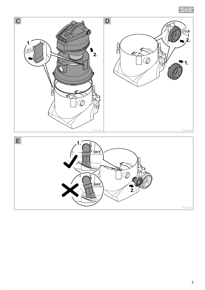
Opening/closing the tank
Attention! Dangerous electrical voltage!
Possible consequences: Death or severe injury.
Protective measures: Prior to commencing work, disconnect the unit from the mains.
How to proceed:
C
1. Release the locking clips.
– To do this, grip the clips from underneath and pull upwards.
2. Lift off the vacuum head and the adapter ring.
– The vacuum head and adapter ring can be removed separately.
– The plug connector for the discharge pump does not need to be disconnected.
3. Assemble the parts in the reverse order and fasten with the locking clips.
– Ensure that the parts are precisely aligned in relation to each other.
– Ensure that the seal on the adapter ring is correctly seated so that it is not damaged during assembly.
Assembling the vacuum cleaner
Fitting the wheels
How to proceed:
D
1. Insert the wheel into the wheel bush.
2. Firmly push the wheel until it locks into place.
Fitting the outlet
Prerequisite: The tank is open.
How to proceed:
E
1. Check the correct seating of the adapter with non-return valve.
– Ensure that the adapter is locked into place in the tank wall.
2. Screw the Storz coupling type C onto the outlet and hand-tighten.
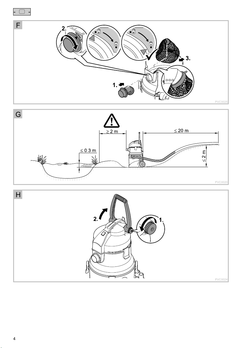
Fitting the inlet
Prerequisite: The tank is open.
How to proceed:
F
1. Insert the intake distributor into the opening.
– Guide the pins on the intake distributor through the notches of the opening.
2. Twist the intake distributor to lock it into place (bayonet closure).
– Ensure that the outlet of the intake distributor in the tank is angled downwards.
3. Fit the debris collection bag onto the intake distributor in the tank.
– Ensure that the elastic of the debris collection bag is seated in the groove of the intake distributor.
– Secure the debris collection bag with the Velcro tape.
- EN -
19
Page 11

- EN -
Installation and connection
G
Attention! Dangerous electrical voltage.
Possible consequences: Death or serious injuries due to operation of electrical units or installations in or
near ponds/pools.
Protective measures:
Set up the unit at least 2 m away from the pond/pool.
Ensure that the ground under the unit is firm and horizontal so that the unit cannot tip over.
Note!
The vacuum cleaner can be set up and operated in a position that is up to 0.5 m lower than the water level.
Possible consequences:
When the vacuum cleaner is switched off, the water will automatically flow through the tank while the suc-
tion hose remains in the pond/pool. The pond/pool will be emptied.
Remedy:
Always take the suction hose out of the pool/pond when the vacuum cleaner is switched off.
Adjusting the transport brace
How to proceed:
H
1. Undo the locking screw.
2. Move the transport brace into the desired position.
3. Hand-tighten the locking screw.
Connecting the hoses and nozzles
How to proceed:
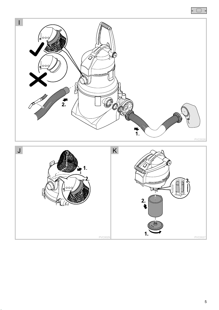
I
1. Attach the discharge hose to the outlet and twist it clockwise (bayonet closure).
– If only coarse dirt particles >1 mm (e.g. leaves or hair) are to be removed, you can allow the waste water to flow
back into the pond / pool via the fine filter bag.
– Do not allow muddy water to flow back into the pond / pool.
2. Attach the suction hose to the inlet.
3. Fit extension tubes and the desired nozzle to the suction hose with handle.
– Universal nozzle: For removing pond sludge without vacuuming up the pond gravel.
– Algae nozzle: For separating and removing string algae.
– Brush nozzle: For removing stubborn dirt.
– Surface cleaning nozzle: For cleaning large, smooth surfaces.
– Wet suction nozzle: For removing dirty or residual water for operation as a wet vacuum cleaner
Note!
The more tubes that are used, the higher the tube frictional resistance. This leads to a reduction of the
suction capacity.
Set up the vacuum cleaner on ground that is not much higher than the water level so as not to impair the
The following conditions must be met:
Allow the dirty water to drain out into a drain or far enough away from the pond to ensure that it cannot flow back
Completely unwind the power and extension cable.
suction capacity.
into the pond.
– Ensure that the cables are not bundled together or coiled up.
20
Page 12

Operation
Switch on the vacuum cleaner at the power switch.
The suction power can be adjusted with the slide in the suction hose handle.
– To increase the suction: Move the slide forwards.
– To reduce the suction: Move the slide backwards.
Clean the vacuum cleaner after each use.
– Recommendation: Vacuum up clean water before cleaning. This will wash out the dirt particles.
Note!
The vacuum cleaner and seals will be subjected to excessive strain if the vacuum cleaner is moved when the
tank is full.
Empty the tank before moving the vacuum cleaner.
Remedy of faults
Malfunction Cause Remedy
The unit does not switch on No mains voltage Switch on mains voltage
The unit cannot be switched on, a warning sig-
nal has sounded.
Water vapour is escaping from the unit. In cold weather condensate forms in the unit,
No suction or reduction in suction No mains voltage Check the mains voltage.
Pump housing, discharge hose or non-return
valve clogged.
Remove dirt
Defective pump Replace the pump.
Plug connector of the pump cable open Close the plug connector.
Moisture in the plug connector of the pump ca-
ble
Discharge hose is too high up. Route the discharge hose in a lower position
The water level in the tank is too high.
The float in the vacuum head has closed the
intake for longer than 15 s.
The float in the vacuum head has closed the
intake three times within 60 s.
which is released in the form of water vapour.
Excessive height difference between water
level and unit
Open the plug connector and allow it to dry.
(max. 2 m above the base of the unit)
Clean the tank.
Ensure that the float can move freely.
To reset the malfunction: Switch off the unit
and then switch it on again.
This is normal. No remedy necessary
Set up the vacuum cleaner on ground that is
not much higher than the water level.
Debris collection bag is full. Empty the debris collection bag.
Dirt clogging the foam filter, suction tube or
suction hose
Remove dirt.
Non-return valve jammed or soiled Clean
- EN -
Low suction capacity Slide on the suction handle is open. Close the slide on the suction handle.
The tank is not emptying, the vacuum head
keeps switching off.
Increased tube friction resistance Keep the suction hose as short and flat as pos-
Excessive suction depth Due to the design the
suction capacity reduces from a suction depth
of 2 m.
Discharge hose kinked
The discharge hose is too high (max. 2 m
higher than the unit).
The discharge hose is too long (max. 20 m).
Discharge hose or non-return valve clogged
with dirt
The discharge pump is clogged.
sible.
Reduce the suction depth
Route the discharge hose correctly.
Remove dirt from the discharge hose.
Clean the non-return valve.
Clean the discharge pump.
Clean the non-return valve.
21
Page 13

- EN -
Maintenance and cleaning
Attention! Dangerous electrical voltage!
Possible consequences: Death or severe injury.
Protective measures: Prior to commencing work, disconnect the unit from the mains.
Cleaning the container
Prerequisite: The tank is open.
Clean the debris collection bag under running water.
Clean the following parts with clean water and a soft brush:
Intake distributor
Discharge pump
Storz coupling type C
– Regularly clean seals, including that of the Storz coupling type C hoses. Soiled seals are subject to increased
wear, leading to leaks.
Inside of the tank
– Recommendation: Place the vacuum head next to the unit (do not open the plug connectors), lay the tank on the
ground and rinse out with running water.
Cleaning the debris collection bag
Prerequisite: The tank is open.
How to proceed:
J
1. Release the Velcro tape of the debris collection bag.
2. Pull the elastic of the debris collection bag from the intake distributor.
3. Remove and empty the debris collection bag.
– Undo the zip on the debris collection bag to facilitate emptying.
– Close the zip after emptying.
4. Refit the debris collection bag in the reverse order.
– Secure the debris collection bag with the Velcro tape.
Cleaning the foam filter
Prerequisite: The tank is open.
How to proceed:
K
1. Release the filter cover (bayonet closure).
2. Pull off the foam filter and clean with clean water and a soft brush.
3. Check the function of the float and clean if necessary.
– Ensure that the float can move freely and easily.
4. Assemble the parts in the reverse order.
Cleaning the non-return valve
Prerequisite: The tank is open.
How to proceed:
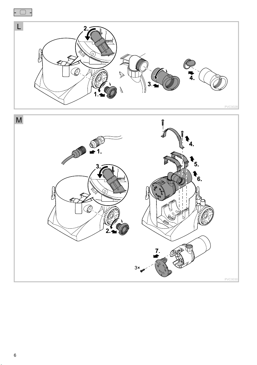
L
1. Unscrew the Storz coupling type C.
2. Turn the adapter away to the side.
3. Unscrew the adapter.
4. Remove the non-return valve.
5. Clean all parts with clean water and a soft brush.
6. Reassemble the parts in the reverse order.
– Important: Ensure that the non-return valve is inserted such that the valve opens in the direction of the outlet.
22
Page 14

Removing/cleaning the pump
Prerequisite: The tank is open.
How to proceed:
M
1. Unscrew the plug connection and pull apart.
– Protect the open plug connection from moisture.
2. Unscrew the Storz coupling type C.
3. Turn the adapter away to the side.
4. Remove the transport protection.
5. Carefully bend open the retaining brace with the tab to release.
6. Remove the discharge pump and clean or replace if defective.
7. Cleaning the discharge pump:
– Undo the screws on the pump casing and remove the protection grid.
– Clean the protection grid and pump casing on the inside and outside with clear water and a soft brush.
– Remove soiling from the impeller unit, turning the impeller unit by hand to access all soiled points.
8. Reassemble the parts in the reverse order.
– The transport protection only needs to be fitted for shipping or horizontal transport of the unit.
Wear parts
The following components are wear parts and are excluded from the warranty:
Foam filter
Debris collection bag
Seals
Wheels
Non-return valve
Impeller unit
Storage/Over-wintering
Drain the unit as far as possible, clean thoroughly and check for damage.
Empty all hoses, pipes and connections as far as possible.
Store the unit in a dry and frost-free place.
Disposal
Do not dispose of this unit with domestic waste! For disposal purposes, please use the return system provided.
Disable the unit beforehand by cutting off the cables.
- EN -
23
Page 15

- EN -
Technical data
Rated voltage V AC 230
Mains frequency Hz 50
Max. power consumption W 2600
Length of power cable m 7.50
Permissible water temperature °C +4 … +35
Weight kg 27
Dimensions L × W × H mm 435 × 395 × 670
Discharge pump Max. delivery rate l/min 233
Vacuum head Max. delivery rate l/min 133
Output Connection 2‘‘ Storz coupling type C
Symbols on the unit
Maximum head height m 11
Maximum head height
(max. submersion depth of suction hose)
m 2.50
Max. length of discharge hose m 20
Discharge pump:
Dust-tight. Watertight to 1 m depth.
Vacuum:
Protection against the ingress of splash water.
Do not dispose of with household waste.
Attention!
Read the operating instructions.
24
Page 16

PVC0031
205
Page 17

206
PVC0032
 Loading...