

Oase BioMaster 250, BioMaster 600, BioMaster 350, BioMaster Thermo 600, BioMaster Thermo 250 Operating Instructions Manual
...Page 1
BioMaster 250/350/600
Downloaded from www.watergardeningdirect.com
BioMaster Thermo 250/350/600
Page 2
2 BioMaster 250/350/600, BioMaster Thermo 250/350/600
A
BMR0003
B
BMR0004
Downloaded from www.watergardeningdirect.com
Page 3
3
C
D
BMR0021
BMR0022
Downloaded from www.watergardeningdirect.com
Page 4
4 BioMaster 250/350/600, BioMaster Thermo 250/350/600
E
F
BMR0008
BMR0009
G
H
BMR0010
BMR0011
Downloaded from www.watergardeningdirect.com
Page 5
5
I
J
BMR0014
BMR0015
K
L
BMR0006
BMR0023
Downloaded from www.watergardeningdirect.com
Page 6

6 BioMaster 250/350/600, BioMaster Thermo 250/350/600
M
FSt0015
N
BMR0026
Downloaded from www.watergardeningdirect.com
Page 7

7
O
BMR0005
P
BMR0007
Downloaded from www.watergardeningdirect.com
Page 8

8 BioMaster 250/350/600, BioMaster Thermo 250/350/600
Q
R
BMR0012
BMR0013
S
T
BMR0016
BMR0017
Downloaded from www.watergardeningdirect.com
Page 9

9
U
BMR0024
Downloaded from www.watergardeningdirect.com
Page 10

10 BioMaster 250/350/600, BioMaster Thermo 250/350/600
V
W
BMR0018
BMR0019
X
BMR0020
Downloaded from www.watergardeningdirect.com
Page 11

- EN -
19
- EN -
Translation of the original Operating Instructions
WARNING
• This unit can be used by chil-
dren aged 8 and above and by
persons with reduced physical,
sensory or mental capabilities
or lack of experience and
knowledge if they are supervised or have been instructed
on how to use the unit in a safe
way and they understand the
hazards involved.
• Do not allow children to play
with the unit.
• Only allow children to carry
out cleaning and user maintenance under supervision.
• Switch off all units in the
aquarium or disconnect the
power plugs of all units before
reaching into the water.
• Do not use the unit if electrical
cables or housings are damaged.
• Only connect the unit if the
electrical data of the unit and
the power supply correspond.
The unit data is to be found on
the unit type plate, on the
packaging or in this manual.
• Disconnect the power plug before carrying out any work on
the unit.
SAFETY INFORMATION
• Never operate the unit if the housing is defective!
• Never operate the unit if any electrical cables are
defective!
• Never carry or pull the unit by the electrical cable.
• Route cables such that they are protected from
damage and do not present a tripping hazard.
• Only open the unit housing or its attendant components if this is explicitly specified in the operating instructions.
• Only carry out work on the unit that is described in
this manual. If problems cannot be overcome,
please contact an authorised customer service point
or, if in doubt, the manufacturer.
• Only use original spare parts and accessories for the
unit.
• Never carry out technical changes to the unit.
• Protect the plug connection from moisture.
• Only connect the unit to a correctly fitted socket.
Symbols used in these instructions
Warnings
The warning information is categorised by signal
words, which indicate the extent of the hazard.
WARNING
• Indicates a possibly hazardous situation.
• Non-observance may lead to death or serious inju-
ries.
NOTE
Information for the purpose of clarification or for preventing possible damage to assets or to the environment.
Additional information
A Reference to a figure, e.g. Fig. A.
→ Reference to another section.
Downloaded from www.watergardeningdirect.com
Page 12

- EN -
20 BioMaster 250/350/600, BioMaster Thermo 250/350/600
PRODUCT DESCRIPTION
Scope of delivery
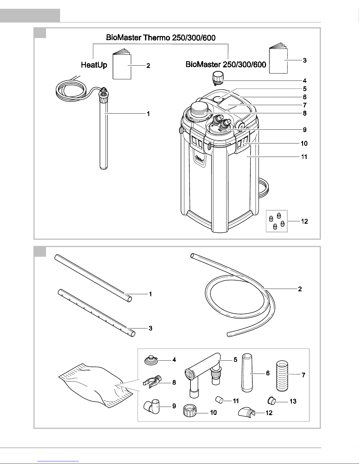
A
BioMaster Thermo
1
BioMaster Thermo 250: HeatUp 150
BioMaster Thermo 350: HeatUp 200
BioMaster Thermo 600: HeatUp 300
2
Operating instructions HeatUp 25/50/75/100/
150/200/250/300
BioMaster, BioMaster Thermo
3
Operating instructions
BioMaster 250/300/600,
BioMaster Thermo 250/300/600
4
Holding ring for HeatUp assembly
5
Blind plug
6
Handle, when the handle is hinged down there are
two fasteners (10), locked
7
Unit head
8
Pre-filter with suction button
9
Connection unit with hose connectors, outlet and inlet
10
Fastener
11
Container, filled with filter media
12
Rubber feet
B
Suction unit, flow-out unit
Quantity
1
Suction pipe
1
2
Hose
1
3
Flow-out pipe
2
4
Suction cup
5
5
Hose adapter, adjustable
2
6
Adapter, suction pipe
1
7
Suction basket
1
8
Terminal
5
9
Angle piece
1
10
Union nut
4
11
Short hose section as connecting piece
for flow-out pipes (3)
1
12
Water distributor
1
13
Cover cap
1
Intended use
BioMaster 250/350/600, BioMaster Thermo
250/350/600, referred to as "unit", may only be used
as specified in the following:
• BioMaster 250/350/600: Water filtering and recir-
culation.
• BioMaster Thermo 250/350/600: Water heating,
filtering and recirculation.
• For operation with freshwater or saltwater.
• Operation under observance of the technical data.
The following restrictions apply to the unit:
• O
nly use indoors and for aquaristic purposes in the
home (not for commercial use).
• Only operate with water at a water temperature of
+4 °C to +35 °C.
Function description
Dr
awn in by a pump in the unit head, the water first
flows through the pre-filter then from the bottom to
the top through the superimposed layers of filter media. The water then flows back into the aquarium via
the flow-out pipe or water distributor.
Foam filters with different pore densities, and Hel-X
bio-elements serve as filter media.
In units with heater, the water is heated during its passage through the filter system.
ACCESSING THE UNIT
NOTE
The following applies to all units with heater:
• Adhere to the rules for careful handling. (→ Careful
handling of the heater)
Careful handling of the heater
CAUTION
Hot surface!
Risk of burns when touching the glass bulb.
• Switch off the heater and allow it to cool down be-
fore removing it from the water.
CAUTION
Risk of breaking the glass!
The glass bulb of the heater can break and cause cuts.
• Take care when handling the heater.
• Allow the heater to cool down first. Do not immerse
it in cold water or pour cold water over it.
Downloaded from www.watergardeningdirect.com
Page 13

- EN -
21
Removing the heater
The heater has to be removed for cleaning and maintenance, and for removing the unit head.
How to proceed:
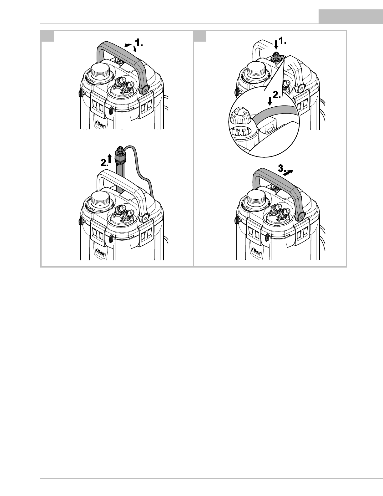
C
1. Hinge up the handle.
2. Unscrew the holding ring together with the heater
counter-clockwise.
Fitting the heater
H
ow to proceed:
D
1. Screw the holding ring with heater clockwise into
the threaded hole.
– T
o exchange the heater: Moisten the glass bulb
with water and push the heater into the holding
ring as far as it goes.
2. Place the power connection cable into the cable
guide.
3. Hinge the handle down.
Removing the connection unit
The heater has to be removed for cleaning and maintenance, and for removing the unit head when hoses are
connected.
How to proceed:
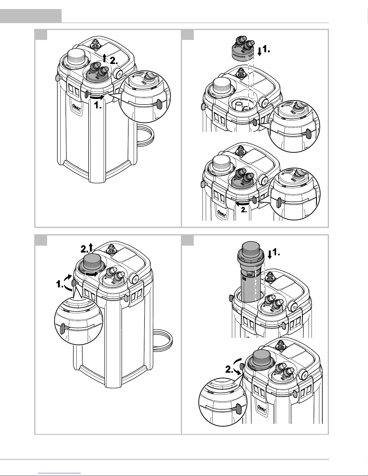
E
1. Push the lever to the "UNLOCK" position.
– T
he lever can only be moved when the pre-filter
is locked.
– T
he inlet and outlet are closed.
2. Remove the connection unit.
Fitting the connection unit
How to proceed:
F
1. Fit the connection unit and push it into the unit
head as far as it goes.
– Ens
ure that the ridges on the connection unit are
correctly aligned to the recesses on the unit
head.
2. Push the lever in the direction "LOCK".
– T
he inlet and outlet are open.
Removing the pre-f
ilter
It has to be removed for cleaning and maintenance
and for removing the unit head.
Prerequisite:
• The inlet and outlet are closed. (→ Removing the
connection unit)
How to proceed:
G
1. P
ush the lever to the "UNLOCK" position.
– T
he lever can only be moved when the inlet and
outlet are closed.
2. Pull out the pre-filter.
Fitting the pre-filter
How to proceed:
H
1. Fit the pre-filter into the opening and firmly push it
into the unit head as far as it goes.
– Ens
ure that the ridges on the pre-filter are cor-
rectly aligned to the recesses on the unit head.
2. Push the lever to the "padlock closed" symbol.
– T
he pre-filter is locked.
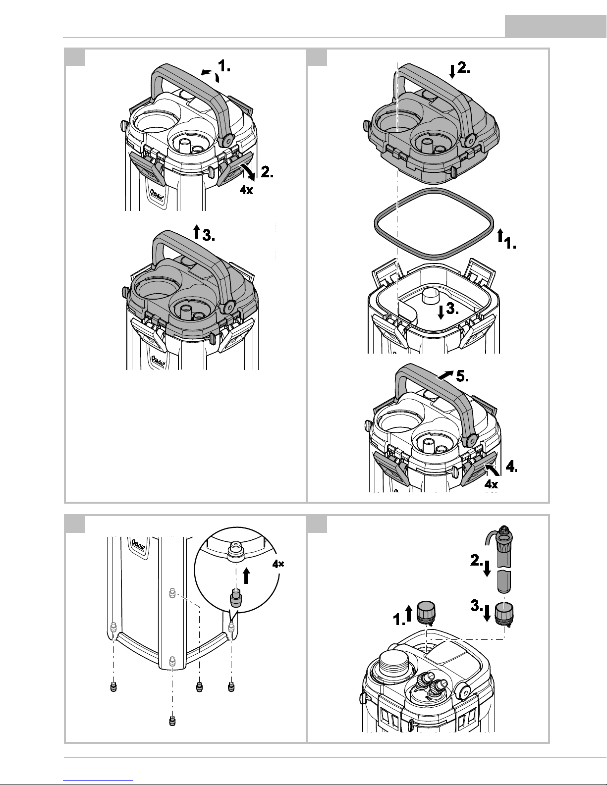
Dismantling the unit head
I
t has to be removed for cleaning and maintenance
and for changing the filter media.
Prerequisite:
• The heater has been removed. (→ Removing the
heater)
• The connection unit has been removed.
(→ Removing the connection unit)
• The pre-filter has been removed. (→ Removing th
e
p
re-filter)
How to proceed:
I
1. Hinge up the handle.
2. Undo the fasteners.
3. Remove the unit head.
Fitting the unit head
How to proceed:
J
1. Check that the seal on the unit head is correctly positioned.
– C
lean the seal, replace it if damaged.
2. Ensure that the filter baskets are correctly assembled and aligned.
3. Fit the unit head onto the container.
– Ens
ure that the opening for the pre-filter is
aligned to the recess in the filter baskets.
4. Lock the fasteners in place.
5. Hinge the handle down.
Downloaded from www.watergardeningdirect.com
Page 14

- EN -
22 BioMaster 250/350/600, BioMaster Thermo 250/350/600
INSTALLATION AND CONNECTION
Order of tasks to be carried out:
1. Fit the unit feet (→ Fitting the unit feed)
2. Prepare the filter media (→ Cleaning/replacing the
filter media)
3. As an option: OASE HeatUp Retrofitting (heater)
(→ Retrofitting the heater)
4. Install the unit.
– I
nstall the unit next to or under the aquarium.
Note the maximum head height. (→ Technical
data)
5. Establish the connections (→ Establishing the con-
nections)
Fitt
ing the unit feed
How to proceed:
K
• Twist the rubber feet into the openings of the container base.
Retrofitting the heater
Bi
oMaster 250/350/600 can be retrofitted with OASE
HeatUp.
• A holding ring is required for fitting (provided in the
delivery scope).
BioMaster
250
350
600
HeatUp
25
50
75
100
150
200
–
250 – –
300 – –
: Suitable : Particularly recommended
Prerequisite:
• The pump is switched off. (→ Switching off the unit)
NOTE
When the filter is filled with water, water may spill
when the heater is inserted.
• Take measures to collect any spillage.
How to proceed:
L
1. Unscrew the blind plug counter-clockwise and remove.
2. Push the heater into the holding ring as far as it
goes.
– Tip: Moisten the glass bulb with water before in-
serting.
3. Fit the heater. (→ Fitting the heater)
Establishing the connections
Assembling the suction unit
How to proceed:
M
• Assemble the suction unit.
• Set the flow rate.
• Use a coin to turn the flow regulator in the hose
adapter to MAX.
Assembling the flow-o
ut unit
How to proceed:
N
• Assemble the flow-out unit.
– T
he water distributor can be used instead of the
flow-out pipe.
• Use a coin to turn the flow regulator in the hose
adapter to MAX.
Connecting the hose
T
he procedure is identical for the inlet (IN) and outlet
(OUT).
How to proceed:
O
• Fasten the suction unit and flow-out unit in the
aquarium using suction cups.
P
1. Shorten the hose to the required length.
– Cho
se the length so that the hose cannot kink in
the intended installation position.
2. Screw the union nut onto the hose connector of the
connection unit.
3. Push the hose onto the hose connector and turn the
union nut counter-clockwise to fix the hose in place.
4. Push the other end of the hose onto the hose connector at the suction unit/flow-out unit and turn the
union nut counter-clockwise to fix the hose in place.
Downloaded from www.watergardeningdirect.com
Page 15

- EN -
23
COMMISSIONING/START-UP
For initial start-up or after thorough cleaning, it is necessary to expel air from the filter system. When the
container, suction unit and hose are free of trapped
air, the pump can convey the water by itself through
the filter system. (→ Expelling air from the filter system)
NOTE
Thoroughly rinse out all filter material with warm tap
water before using for the first time in order to remove
any soiling. (→ Cleaning/replacing the filter media)
Expelling air from the filter system
Prerequisite:
• The pump is switched off. (→ Switching off the unit)
How to proceed:
Q
1. Press the suction button and release it until the water flows out of the tank into the filter.
– The filter is completely flooded when water
emerges from the flow-out unit.
Switching on the unit
NOTE
Ensure that the pump never runs dry!
The pump will be destroyed.
• Regularly check the water level and circulation in
the filter and in the aquarium.
NOTE
Risk of fire due to the hot surface of the heater!
The heater and filter can be destroyed by the generated heat.
• Do not switch the heater on until the filter is completely filled with water, switched on and the water
is continuously circulated.
• Switch off the heater and allow it to cool down before removing it from the water.
How to proceed:
R
1. Route each power connection cable such that it
forms a drip loop.
2. Connect the power connection cable to the power
supply.
– T
he pump will switch on immediately.
– T
rapped air in the filter can cause noise. The
trapped air escapes shortly after the pump starts
up.
3. Unit with heater: Set the water temperature on the
heater and switch on the heater. (→ Heater operating manual).
Switching off the unit
H
ow to proceed:
• Disconnect the unit from the power supply
• Unit with heater: Disconnect the unit and heater
from the power supply
Setting the flow rate
H
ow to proceed:
S
• Move the lever on the connection unit to set the desired flow rate
– "
LOCK": Maximum flow rate
– "
UNLOCK": No flow, the outlet is closed.
Downloaded from www.watergardeningdirect.com
Page 16

- EN -
24 BioMaster 250/350/600, BioMaster Thermo 250/350/600
REMEDY OF FAULTS
Malfunction
Cause
Remedy
Unit does not start up.
No mains voltage
Check the mains voltage.
Impeller unit blocked
Clean
Air in the filter
Vent the filter. Move the filter from side to
side, if necessary, to allow the remaining air
to escape.
Water flow insufficient
Impeller unit soiled
Clean
Impeller unit worn
Replace the impeller unit.
The flow is not correctly set.
Correct the setting.
Foam filter of the pre-filter soiled
Clean
Filter media in the container soiled
Clean
Suction basket clogged
Clean
Pipework soiled
Clean suction unit, flow-out unit and hoses.
Insufficient filtering performance
Foam filter of the pre-filter soiled
Clean
Foam filter of the pre-filter worn
Replace
Filter media in the container soiled
Clean
Filter media in the container worn
Replace
Insufficient water heating
(only units with heater)
Heater defective
Replace
Heater not calibrated
Calibrate
Water temperature incorrectly set on the
heater
Correct the water temperature setting on
the heater.
Water flow insufficient
See malfunction "Water flow insufficient"
The filter cannot be vented.
Valve box in the pre-filter blocked
Clean the valve box.
Filter is not below the surface of the water.
Install the filter below the surface of the
water.
Increased noise
Air in the filter
Move the filter from side to side to allow
the remaining air to escape.
MAINTENANCE AND CLEANING
• If necessary, clean with clear water using a soft
br
ush.
• Do not use cleaning agents or chemical solutions.
We recommend using OASE PumpClean for removing calcium deposits.
• Cleaning and replacement cycles for filter media are
dependent on the size of the aquarium and the
number of fish. Therefore, it is necessary to clean
and replace the filter media as required to ensure
optimum filter performance.
• If there are several foam filters: Clean or replace the
foam filters at different times. This saves enough
useful bacteria to ensure good biological filtration
of the water.
NOTE
Thoroughly rinse out all filter material with warm tap
water before using for the first time in order to remove
any soiling. (→ Cleaning/replacing the filter media)
Cleaning and maintenance work:
Area
Tasks to be carried out
Foam filter, pre-filter
(→ Cleaning/replacing the foam filter of the pre-filter)
Filter media, container
(→ Cleaning/replacing the filter media)
Heater
HeatUp 25/50/75/
100/150/200/250/300
Impeller unit, pump
casing
(→ Cleaning/replacing the impeller
unit)
Valve box, pre-filter
(→ Cleaning the valve box of the prefilter)
Suction chamber, prefilter
(→ Cleaning the suction chamber of
the pre-filter)
NOTE
The cycle for cleaning the foam filter in the pre-filter is
longer if a coarser foam filter is used.
Downloaded from www.watergardeningdirect.com
Page 17

- EN -
25
Cleaning/replacing the foam filter of the pre-filter
Prerequisite
• The pre-filter has been removed. (→ Removing th
e
p
re-filter)
How to proceed:
T
1. Press in the engagement hooks on the pre-filter and
pull off the housing.
2. Remove the pre-filter pipe and foam filters.
– Bi
oMaster 250: 4 foam filters.
– BioMaster 350: 5 foam filters.
– Bi
oMaster 600: 6 foam filters.
3. Rinse the foam filters in warm water. If necessary,
replace the foam filters.
4. Assemble the pre-filter in the reverse order.
Cleaning/replacing the filter media
U
Filter media on delivery:
a
Foam filter 30 ppi
b
Foam filter 20 ppi
c
Hel-X bio-elements, always place them contained
in the bag into the strainer casing
Prerequisite
• The unit head is removed. (→ Dismantling the unit
head)
How to proceed:
U
1. Remove all filter baskets.
2. Clean the filter baskets and container.
3. Rinse the filter media in warm water. If necessary,
replace the filter media.
4. Place the parts into the container in the reverse order.
– Ca
refully fit the filter baskets in the bottom recess in the container. Correctly position the prefilter.
5. Reassemble the unit in the reverse order.
Cleaning/replacing the impeller unit
Prerequisite
• The unit head is removed. (→ Dismantling the unit
head)
How to proceed:
V
1. Turn the pump lid counter-clockwise (bayonet lock)
and remove.
2. Remove the impeller unit and clean. If necessary, replace.
3. Fit the impeller unit, replace the pump lid and lock
(turn clockwise).
– Ens
ure that the two rubber bearings are correctly
seated.
4. Reassemble the unit in the reverse order.
Cleaning the valve box of the pre-filter
The valve box only has to be cleaned if venting does
not function even though the foam filters of the prefilter have been cleaned.
Prerequisite
• The pre-filter has been removed. (→ Removing th
e
p
re-filter)
How to proceed:
W
1. Undo the fasteners and pull off the valve box.
– I
f necessary, carefully lift the fasteners using a
screwdriver.
2. Remove the valve seal and both valve flaps. Clean
all parts.
3. Assemble the valve box in the reverse order.
– Ens
ure that the fitted valve flaps can be easily
moved.
– Note: Ensure that the opening in the valve seal is
precisely aligned to the opening in the suction
chamber.
Cleaning the suction cham
ber of the pre-filter
The suction chamber only has to be cleaned if venting
does not function even though the foam filters and
valve box of the pre-filter have been cleaned.
Prerequisite
• The pre-filter has been removed. (→ Removing th
e
p
re-filter)
CAUTION
There is a strong spring in the suction chamber that
can act like a projectile.
Risk of injury due to parts flying around
• When opening the suction button, do not point it at
persons.
• Firmly hold the suction button.
How to proceed:
X
1. Press in the engagement hooks, hold and turn the
locking ring counter-clockwise (bayonet lock).
2. Carefully lift the suction button until the tension of
the spring is relieved.
3. Remove the suction button and spring.
4. Clean the suction chamber.
5. Assemble the suction chamber in the reverse order.
Downloaded from www.watergardeningdirect.com
Page 18

- EN -
26 BioMaster 250/350/600, BioMaster Thermo 250/350/600
WEAR PARTS
• Filtration medium
• Impeller unit
• Suction cups
DISPOSAL
NOTE
Do not dispose of this unit with domestic waste.
• Render the unit unusable beforehand by cutting the
cables and dispose of the unit via the return system
provided for this purpose.
SPARE PARTS
The use of original parts from OASE ensures continued
safe and reliable operati
on of the unit.
Please visit our website for spare parts drawings and
spare parts.
www.oase-livingwater.com/spareparts
TECHNICAL DATA
Description
BioMaster, BioMaster Thermo
250
350
600
Rated voltage
V AC
230
230
230
Mains frequency
Hz
50
50
50
Protection type
IPX4
IPX4
IPX4
Power consumption, filter
W
15
18
22
BioMaster Thermo
Power consumption, heater
W
150
200
300
Flow rate
Max.
l/h
900
1100
1250
Head height
Max. m 1.3
1.4
1.8
Max. head height
Max. m 1.8
1.8
1.8
Filter volume
l
4.4
5.6
6.8
Pre-filter volume
l
0.4
0.5
0.6
Recommended for an aquarium volume of
l
250
350
600
Length of power connection cable
m
1.5
1.5
1.5
Connection of hose connectors
Diameter
mm
17
17
17
Dimensions
Length
mm
240
240
240
Width
mm
240
240
240
Height
mm
370
425
480
Weight
kg
4.1
4.5
5.0
SYMBOLS ON THE UNIT
Splash-water protected on all sides.
Protection class II, protection insulation which could become live in the event of a fault.
For use indoors.
Do not dispose of with household waste.
Read and adhere to the instructions for use.
Downloaded from www.watergardeningdirect.com
Page 19

54737/0
8-17
Downloaded from www.watergardeningdirect.com
 Loading...